Review

Progress in Passive Silicon Photonic Devices: A Review

1
School of Electrical and Computer Engineering, University of Georgia, Athens, GA 30605, USA
2
Department of Electrical Engineering, The Pennsylvania State University, State College, PA 16802, USA
3
Department of Education Psychology, University of Georgia, Athens, GA 30605, USA
*
Author to whom correspondence should be addressed.
Photonics 2025, 12(9), 928; https://doi.org/10.3390/photonics12090928
Submission received: 10 August 2025 / Revised: 1 September 2025 / Accepted: 17 September 2025 / Published: 18 September 2025
(This article belongs to the Special Issue Recent Progress in Integrated Photonics)

Abstract

Silicon photonics has emerged as a critical enabling technology for a diverse range of applications, from high-speed data communication and computing to advanced sensing and quantum information processing. This paper provides a comprehensive review of recent progress in the foundational passive devices that underpin this technological revolution. We survey the state of the art in fundamental building blocks, including strip, rib, and silicon nitride waveguides, with a focus on achieving ultra-low propagation loss. The review details essential components for light coupling and splitting, such as grating couplers, edge couplers, multimode interference couplers, and directional couplers, citing their typical performance metrics. Key wavelength filtering and routing components, including high-Q ring resonators, Mach–Zehnder interferometers, and arrayed waveguide gratings, are analyzed. Furthermore, we provide a comparative overview of the capabilities of major photonic foundries operating on a multi-project wafer model. The paper concludes by discussing persistent challenges in packaging and polarization management, and explores future trends driven by co-packaged optics, inverse design methodologies, and the expansion of silicon photonics into new application domains.

1. Introduction

1.1. The Imperative for Silicon Photonics in the AI and Zettabyte Era

The relentless expansion of the digital economy, propelled by the explosive growth of artificial intelligence (AI) [1], machine learning (ML) [2], cloud computing [3], and high-performance computing (HPC) [4], has created an unprecedented demand for data movement [5]. This surge in traffic, particularly within and between the massive data centers that form the backbone of modern computation, has pushed traditional copper-based electrical interconnects to their fundamental physical limits. As data rates climb, copper links face overwhelming challenges in bandwidth, power consumption, signal integrity, and physical density. This has created a critical bottleneck where data transfer, rather than data processing, becomes the primary constraint on system performance, especially for AI workloads that require massive, parallel data exchange between processors, memory, and storage.
Silicon photonics (SiPh) has emerged as a transformative technology to resolve this interconnect crisis. By using photons to carry information instead of electrons, SiPh leverages the intrinsic advantages of optical communication: much higher bandwidth, lower latency, significantly reduced power consumption per bit, and complete immunity to electromagnetic interference (EMI). In today’s “Zettabyte Era”, SiPh technology is more important than ever. The performance of AI systems, including the large language models behind generative AI, is directly held back by the hardware’s ability to handle data coming in and out. Indeed, over 90% of the inference operations in the neural networks foundational to these models are constrained by data transfer bottlenecks that silicon photonics is uniquely positioned to solve [6].
A pivotal factor accelerating the adoption of SiPh is its profound synergy with the mature Complementary Metal–Oxide–Semiconductor (CMOS) manufacturing ecosystem. This convergence allows for the fabrication of complex photonic integrated circuits (PICs) using the same high-volume, high-precision, and cost-effective processes developed over decades for the microelectronics industry. This manufacturability at scale is enabling a historic transition from discrete optical components to highly integrated systems on a chip, mirroring the evolutionary path of electronic integrated circuits [7]. As the technology matures, it is becoming the foundational platform not only for next-generation data centers and 5G/6G telecommunications but also for disruptive new applications in quantum computing, LiDAR for autonomous systems, and advanced biomedical and environmental sensing [8,9].

1.2. Passive vs. Active Devices in PICs

A photonic integrated circuit is a microchip that contains two or more photonic components to form a functioning circuit, manipulating light on a semiconductor substrate. These components can be broadly categorized into two classes: passive and active.
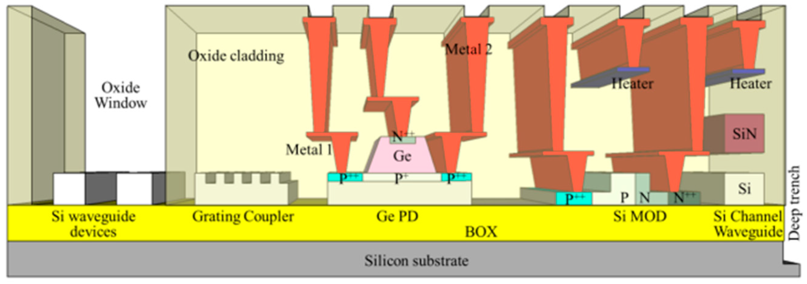
Passive optical components are devices that perform their function without requiring external power or active control. They are the fundamental pipes of a PIC, responsible for manipulating the flow of light through processes such as guiding, splitting, combining, filtering, and coupling. Examples include waveguides, which confine and direct light; couplers and splitters, which distribute optical power; and filters, which select specific wavelengths, as shown in Figure 1. These components are essential for managing and routing optical signals with minimal loss and interference, forming the foundational infrastructure upon which all other on-chip functionalities are built.
In contrast, active devices require an external power source to perform their function, which typically involves converting signals between the electrical and optical domains or actively modifying the properties of the light signal itself. This category includes modulators, which encode electrical data onto an optical carrier; photodetectors, which convert optical signals back into electrical ones; and light sources such as lasers and amplifiers.
This review will focus exclusively on the state of the art and recent progress in passive silicon photonic devices. While active components are critical for a complete system, the performance, efficiency, and scalability of any PIC are ultimately supported by the quality and sophistication of its passive device library.

1.3. Overview of the Review

This paper provides a comprehensive review of the recent progress in passive silicon photonic devices. Section 2 begins with the most fundamental building block, the optical waveguide, reviewing the primary architectures (strip, rib, SiN) and the advanced concept of sub-wavelength grating metamaterials. Section 3 examines the critical components for light coupling and splitting, detailing the performance of fiber-to-chip couplers and on-chip power splitters. Section 4 delves into devices for wavelength filtering and routing, including microring resonators, Mach–Zehnder interferometers, and arrayed waveguide gratings. Section 5 presents a comparative overview of the global fabrication landscape, introducing the multi-project wafer model and profiling the capabilities of major silicon photonics foundries. Section 6 discusses the persistent challenges facing the field, such as polarization management and packaging, and explores future trends including co-packaged optics, inverse design, and new applications in quantum and sensing. Finally, Section 7 provides a summary of the key findings and a concluding perspective on the field’s trajectory.

2. Fundamental Building Blocks: Waveguides for Light Confinement and Propagation

The optical waveguide is the most fundamental component in any photonic integrated circuit, serving as the channel for confining and propagating light across the chip. The performance of virtually all other passive and active devices is directly dependent on the properties of the underlying waveguide. The primary goal in waveguide design is to achieve low propagation loss while maintaining sufficient optical confinement to enable compact routing and device footprints. This section reviews the principal waveguide architectures that form the foundation of modern silicon photonics.

2.1. Conventional Silicon Waveguide Architectures on SOI

The silicon-on-insulator (SOI) platform is the most mature and widely used material system for silicon photonics. It consists of a thin crystalline silicon device layer on top of a thicker buried oxide (BOX) layer, which itself sits on a silicon handle wafer. The large refractive index contrast between the silicon core (n ≈ 3.47 at 1550 nm) and the silicon dioxide (SiO2) cladding (n ≈ 1.45) enables strong light confinement [10].

2.2. Strip Waveguides

Strip waveguides, as shown in Figure 2a, are formed by fully etching through the silicon device layer to define a rectangular core, typically with sub-micron cross-sectional dimensions (e.g., 450–500 nm wide and 220 nm high for single-mode operation at 1550 nm) [11].
The primary advantage of this architecture is its extremely strong optical confinement. This high confinement allows for very tight bending radii, as small as a few micrometers, without significant radiation loss. This capability is critical for realizing highly compact devices, such as microring resonators with a large free spectral range (FSR), and for enabling dense integration of complex circuits on a single chip.
However, this strong confinement comes at a cost. The optical mode is tightly concentrated within the core, leading to significant interaction with the waveguide’s top, bottom, and sidewall interfaces. While the top and bottom surfaces are typically very smooth, the vertical sidewalls are defined by the etching process, which inevitably introduces roughness. This sidewall roughness is a major source of scattering, which is the dominant loss mechanism in strip waveguides. The scattering loss scales strongly with the refractive index contrast, making it particularly pronounced in the high-contrast SOI system.
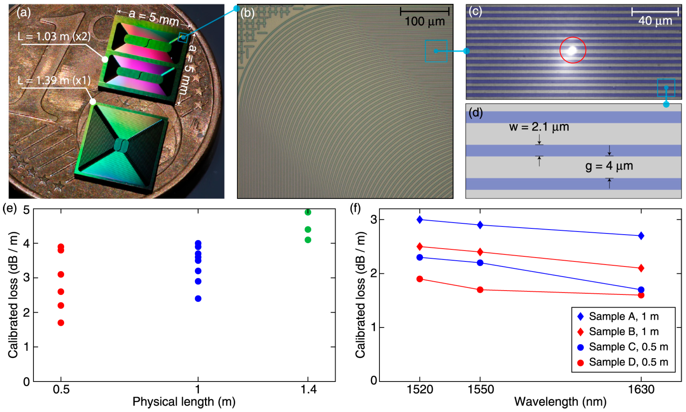
Historically, propagation losses for strip waveguides were in the range of 1–3 dB/cm [12,13]. However, continuous improvements in lithography and etching processes have led to significant reductions. More recent work on standard 220 nm SOI platforms has demonstrated propagation losses for transverse-electric (TE) polarized light of 2.4 dB/cm [14]. Furthermore, research has shown that operating at longer wavelengths can reduce loss; a record-low propagation loss of approximately 0.2 dB/cm was achieved for a 700 nm wide single-mode strip waveguide operating in the 2 µm wavelength band. This improvement is attributed to the weaker optical field intensity at the waveguide sidewalls at longer wavelengths compared to the standard 1550 nm band [15].

2.3. Rib Waveguides

Rib waveguides are designed to directly address the challenge of sidewall scattering loss. In this architecture, the silicon device layer is only partially etched, leaving a thinner slab of silicon on either side of the central, thicker guiding region [16]. This geometry alters the mode profile, allowing the optical field to spread laterally into the un-etched slab regions [17]. Consequently, the mode’s overlap with the rough, vertically etched sidewalls is significantly reduced, leading to a dramatic decrease in propagation loss, as shown in Figure 2b.
The primary advantage of the rib waveguide is its potential for ultra-low loss. The trade-off for this reduced loss is weaker optical confinement compared to a strip waveguide. This weaker confinement necessitates much larger bending radii, typically in the range of tens of micrometers or even millimeters to prevent excessive radiation loss [18]. This limits the ultimate integration density achievable with rib waveguide-based circuits.
The performance of rib waveguides has seen remarkable progress, with reported losses moving from the dB/cm to the dB/m regime, a critical achievement for applications requiring long optical paths like delay lines, gyroscopes, and ultra-high-Q resonators. Early work on shallow-ridge waveguides on 250 nm SOI achieved an average propagation loss of 0.274 dB/cm using standard lithography and dry etching, a figure that was state-of-the-art at the time [11]. A key strategy for further loss reduction is to use thicker SOI wafers and a very shallow etch. By fabricating rib waveguides on a 500 nm thick SOI platform with a rib height of only ~10% of the total silicon thickness (a 56 nm etch), researchers have demonstrated propagation losses as low as 4 dB/m (0.04 dB/cm) [16]. An alternative fabrication approach involves using anisotropic wet etching with chemicals like tetramethylammonium hydroxide (TMAH). This process selectively etches crystal planes, resulting in waveguide sidewalls that are atomically smooth. This technique has been used to achieve propagation losses of 0.85 dB/cm for TE polarization and 1.08 dB/cm for TM polarization [10].
This evolution highlights a fundamental trade-off in waveguide design between optical confinement and propagation loss. While strip waveguides prioritize density and rib waveguides prioritize low loss, advanced fabrication techniques are continuously mitigating this trade-off, enabling complex, large-scale PICs that require both low loss and reasonable compactness.

2.4. The Silicon Nitride (SiN) Platform: A Key Alternative

While SOI is the dominant platform, silicon nitride (SiN) has emerged as a powerful and complementary material for passive photonic devices, as shown in Figure 2c. SiN is a dielectric material that is fully compatible with CMOS fabrication processes and offers a unique set of properties that make it highly attractive for specific application [19]. It has a moderate refractive index of approximately 2.0, which provides good confinement when cladded with SiO2 while being less sensitive to fabrication imperfections than the higher-contrast silicon system [20].
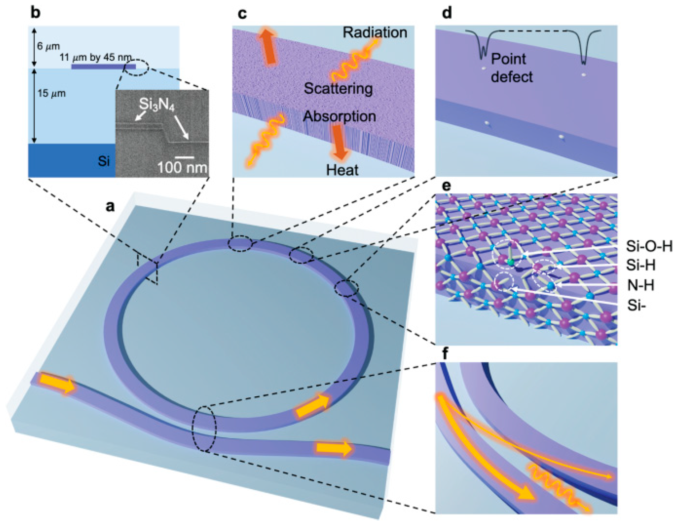
The key advantages of the SiN platform are its ultra-low propagation loss, broad transparency window, and high-power handling. SiN waveguides are renowned for their exceptionally low propagation losses, which are now routinely in the dB/m range [21]. This is primarily due to the lower refractive index contrast, which reduces scattering from sidewall roughness, and the high quality of SiN films deposited via processes like Low-Pressure Chemical Vapor Deposition (LPCVD). Recent demonstrations have reported losses as low as 0.045 dB/m [22], 1.4 dB/m [23], and, after high-temperature annealing to drive out hydrogen impurities, an astonishing 0.06 dB/cm [24]. Foundries like AIM Photonics now target SiN waveguide losses of below 1 dB/cm in their standard processes [25,26].
Unlike silicon, which becomes opaque below ~1.1 µm, SiN is transparent over a very wide wavelength range, from the visible (~400 nm) to the mid-infrared. This makes it an ideal platform for applications outside the traditional telecom bands, such as visible-light photonics for quantum information and displays, or MIR sensing [27]. Furthermore, SiN exhibits negligible two-photon absorption at telecom wavelengths, a nonlinear effect that can be a limiting factor in silicon waveguides. This property allows SiN devices to handle much higher optical powers, making them the platform of choice for nonlinear applications like frequency comb generation and parametric amplification [19].
A significant challenge in SiN photonics has been the high intrinsic tensile stress of the films, particularly for the thick layers (≥600 nm) required for dispersion engineering in nonlinear applications. This stress can lead to film cracking and wafer bowing, especially on large 300 mm wafers. A breakthrough solution to this problem is the photonic Damascene process [28]. In this method, instead of depositing SiN and then etching it, trenches are first etched into the SiO2 cladding. SiN is then deposited to fill these trenches, and the excess is removed via chemical mechanical planarization (CMP). This process effectively mitigates the stress issue, enabling the fabrication of ultra-low-loss, thick SiN waveguides on large-scale wafers. As shown in Figure 3, the photonic Damascene process has been demonstrated to enable the high-yield, wafer-scale fabrication of high-performance, dispersion-engineered SiN photonic circuits with ultra-low loss [29]. In conclusion, Table 1 provides a summary of the key performance metrics for each Si and SiN waveguide.

2.5. Advanced Waveguide Engineering: Sub-Wavelength Grating (SWG) Metamaterials

Sub-wavelength grating (SWG) waveguides represent a paradigm shift in device design, moving from using silicon as a simple wave-guiding medium to engineering its properties at a sub-wavelength scale to create an artificial optical material or metamaterial [30,31,32]. An SWG waveguide consists of a periodic arrangement of silicon segments interleaved with a low-index material (like the SiO2 cladding), where the period of the grating, or pitch (Λ), is small enough to suppress diffraction effects. For light propagating along the grating, if the pitch is below the Bragg condition ( Λ < λ 0 2 n e f f ), the structure behaves not as a series of discrete scatterers but as a continuous, homogeneous waveguide with unique, engineered properties.
The key characteristic of SWGs is the ability to achieve index engineering. By intentionally designing the geometry of the sub-wavelength segments, the effective refractive index of the equivalent metamaterial can be precisely controlled. The periodic structure is inherently anisotropic, meaning its effective refractive index is different for electric fields oscillating parallel or perpendicular to the grating segments. This engineered anisotropy provides an extra degree of freedom unavailable in conventional solid-core waveguides.
This design flexibility has enabled breakthrough performance and novel functionalities across a wide range of passive devices. SWGs are used to create ultra-broadband and highly efficient fiber-to-chip couplers with low polarization dependence [33]. SWG-based MMI [34] and directional couplers [35] can also be made more compact and can operate over much wider bandwidths than their conventional counterparts. Furthermore, the engineered anisotropy of SWGs is ideal for creating compact and efficient polarization splitters and rotators [36]. SWGs also allow for precise control over the waveguide’s group velocity dispersion, a critical parameter for nonlinear optics and for compensating dispersion in communication links.
This approach marks a conceptual leap from geometric optics to metamaterial engineering on a chip. Instead of being constrained by the intrinsic properties of bulk silicon, designers can now synthesize a material with the exact optical properties required for a specific application. While introducing nanoscale features, these waveguides can maintain low propagation losses comparable to standard strip waveguides, with values around 3.7 dB/cm reported for metamaterial-clad structures designed to reduce crosstalk [37].

3. Light Coupling and Splitting: The Interface to and Within the Chip

Efficiently coupling light from an external source, typically a single-mode optical fiber, onto the photonic chip and subsequently distributing that light to various functional blocks are fundamental requirements for any PIC. The performance of these coupling and splitting components directly impacts the overall insertion loss and power budget of the entire system. This section reviews the state of the art in fiber-to-chip couplers and on-chip power splitters.

3.1. Fiber-to-Chip Couplers

A significant challenge in silicon photonics is bridging the immense size mismatch between the mode field diameter of a standard single-mode optical fiber (~9–10 µm) and that of a sub-micron silicon waveguide (~0.5 µm). Two primary strategies have been perfected to address this challenge: grating couplers and edge couplers.

3.1.1. Grating Couplers (GCs)

Grating couplers are periodic structures, such as etched lines in the silicon waveguide, that act as a diffraction grating. They are designed to scatter light out of the plane of the chip at a specific angle that matches the acceptance angle of an optical fiber positioned vertically above it [38]. A key advantage of this out-of-plane coupling scheme is that it allows for testing at any point on a wafer’s surface without requiring the wafer to be diced. This makes GCs ideal for high-throughput, wafer-scale characterization of devices during R&D and manufacturing [39].
The performance of GCs is defined by their coupling efficiency (CE) and optical bandwidth. Historically, the CE of simple GCs was limited to around 30–40% (−5 to −3 dB) due to two primary loss mechanisms: back-reflection into the waveguide and power leakage downwards into the silicon substrate. Modern GC design has largely overcome these limitations through sophisticated engineering. Techniques include adding a bottom reflector (e.g., a metal layer or a distributed Bragg reflector) to redirect substrate-bound light upwards, and apodizing the grating (varying the etch depth or duty cycle along its length) to shape the diffracted beam into a more Gaussian-like profile that better matches the fiber mode. More recently, inverse design methods have been used to create non-periodic “meta-gratings” that achieve unprecedented performance. State-of-the-art designs have demonstrated experimental CEs of 78% (1.08 dB) [40] and 81.57% (1.76 dB) [41]. For polarization-diverse applications, two-dimensional (2D) GCs have been developed, with a recent foundry-compatible design achieving a measured CE of 2.54 dB (56%) [42].
Standard uniform GCs are inherently wavelength-sensitive, typically having a 1 dB bandwidth of 30–40 nm. However, advanced designs that engineer the grating’s dispersion can significantly broaden this operational window. Bandwidths of 80–90 nm (1 dB) [39] and 92 nm (3 dB) [41] are now achievable. While most GCs are on SOI, SiN platforms are also used. The lower index contrast of SiN results in weaker grating strength and typically lower CE. However, hybrid platforms that use an amorphous silicon or polysilicon overlay on top of the SiN waveguide can enhance the grating strength, enabling CEs approaching 1 dB [43].

3.1.2. Edge Couplers (ECs)

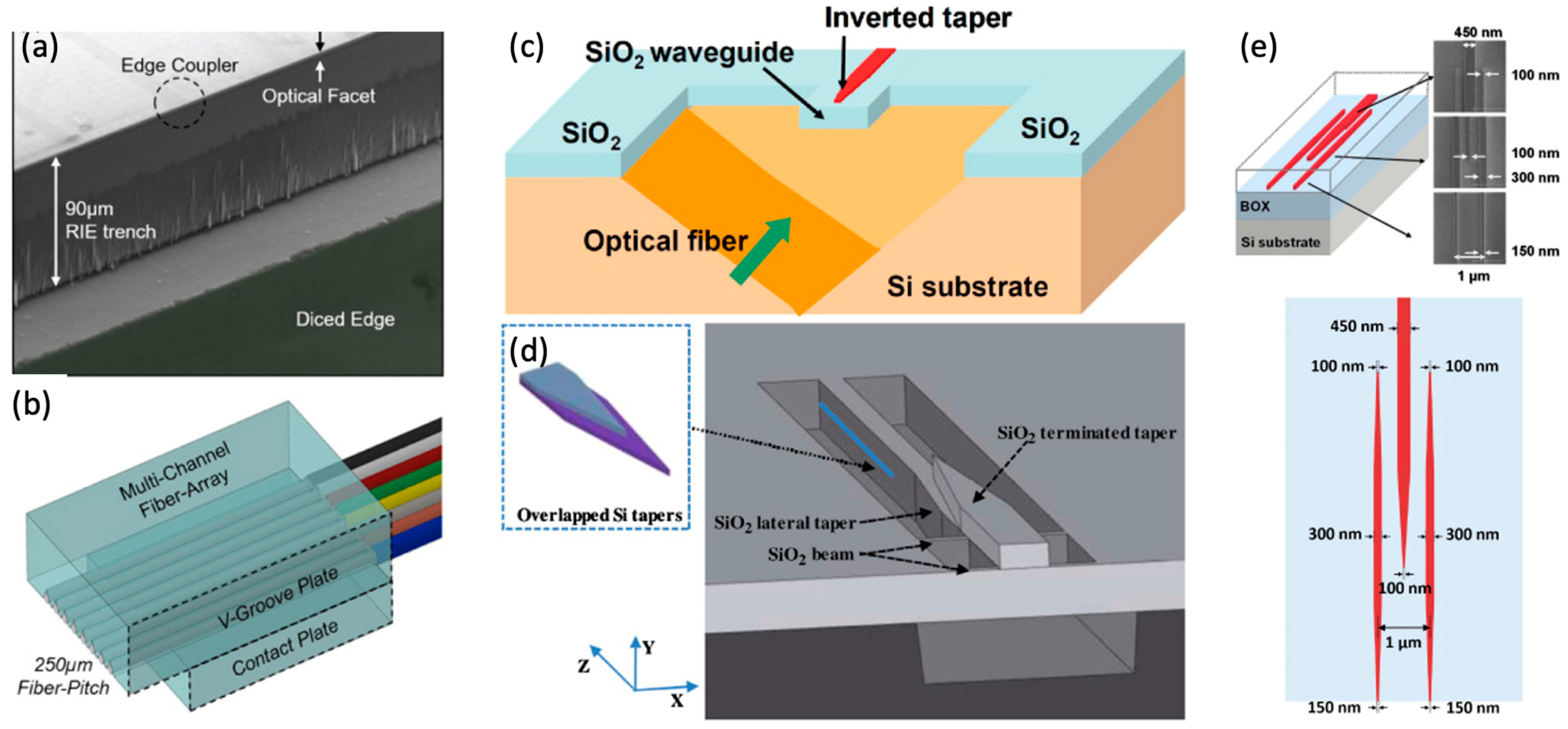
Edge couplers facilitate in-plane coupling, where the optical fiber is brought to the polished facet of the chip. The core component of an EC is a mode-size converter, most commonly an inverted taper. This is a section of the waveguide that gradually narrows towards the chip facet. As the waveguide width decreases, the optical mode becomes less confined and expands in size, allowing for a much better mode-field overlap with the larger mode of the optical fiber [44].
Edge couplers are renowned for their superior performance in terms of efficiency and bandwidth. ECs can achieve near-unity coupling efficiency. By using multiple stacked tapers or multi-tip structures to precisely shape the output mode in both the horizontal and vertical dimensions, losses can be minimized, as shown in Figure 4. Recent demonstrations on the SiN platform have achieved simulated CEs of over 90% across a 1000 nm wavelength range (1000–2000 nm) and a record-high measured CE of 97.1% (−0.13 dB) [45]. On other platforms like thin-film lithium niobate (TFLN), CEs of −1.52 dB (70%) are reported [46]. Furthermore, a major advantage of ECs is their inherently ultra-broad bandwidth and low polarization dependence compared to GCs [45]. A 1 dB bandwidth of over 270 nm has been demonstrated [47], and polarization-dependent loss (PDL)—the difference in coupling loss between TE and TM polarizations—can be as low as < 0.17 dB [48]. Moreover, power handling that can be as high as 520 mW with <0.6/0.8 dB TE/TM insertion loss has been demonstrated recently [49].
The historical trade-off between the wafer-scale testing convenience of GCs and the superior performance of ECs is rapidly diminishing. As both architectures converge towards high efficiencies, the choice of coupler is becoming less about a performance compromise and more about a system-level design choice dictated by packaging and testing strategy, as shown in Table 2. This convergence is a hallmark of a maturing technology platform.

3.2. On-Chip Power Splitters and Routers

Once light is on the chip, it must be divided and routed to different functional units. The primary components for this task are Y-branches, multimode interference couplers, and directional couplers.

3.2.1. Y-Branch Splitters

The Y-branch is the simplest and one of the most robust power splitters, consisting of a single input waveguide that symmetrically bifurcates into two output waveguides [51]. While conventional Y-branches with a sharp, wide-angle split suffer from significant optical radiation loss, modern designs have largely mitigated this issue. By using a very gradual, adiabatic split or by inserting a specially designed mode-evolution region at the junction, excess loss (the loss beyond the ideal 3 dB split) can be made negligible.
An optimized silica-on-silicon Y-branch using a tapered multimode section reported an excess loss of just 0.12 dB [52]. A design on SiN, optimized for low-loss quantum applications, achieved a loss of <0.1 dB [53]. Additionally, a power splitter based on adiabatically tapered rib waveguides, which functions as a mode evolution Y-branch, demonstrated an exceptionally low excess loss of 0.06 dB [54].

3.2.2. Multimode Interference (MMI) Couplers

MMI couplers are based on the self-imaging principle. Light from one or more input waveguides enters a much wider multimode waveguide section. Within this section, the various excited modes propagate at different phase velocities, interfering with each other. At specific lengths along the MMI section, the interference pattern reproduces one or more images of the input field at the output waveguides [55]. MMI devices are prized for their compact size, broad optical bandwidth, and high tolerance to fabrication variations. As shown in Figure 5, a Si-based 4 × 4 MMI was demonstrated with 100G channel width, high channel uniformity with less than 1 dB excess loss, and 12.7 dB crosstalk in [56].
Recent low-loss 2 × 2 MMI couplers fabricated on a SiN platform achieved a measured insertion loss of only 0.07 dB at 1310 nm, with loss remaining below 0.25 dB across the entire O-band [57]. A 1 × 4 MMI splitter on SiN reported a similarly low insertion loss of 0.13 dB [55].

3.2.3. Directional Couplers (DCs)

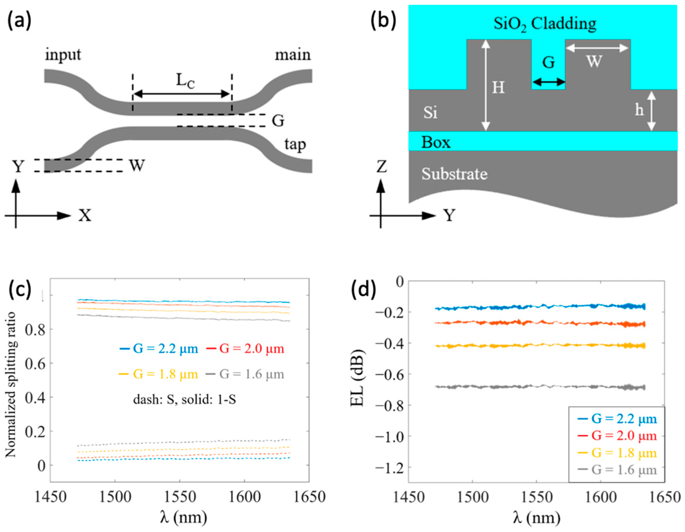
A directional coupler consists of two parallel waveguides placed in close proximity. Their evanescent fields overlap, allowing power to be gradually transferred from one waveguide to the other. The amount of power transferred (the coupling ratio) depends sensitively on the interaction length, the gap between the waveguides, and the wavelength [54].
While this wavelength sensitivity can be a drawback, it can also be exploited for wavelength-division multiplexing. Moreover, recent advanced designs have focused on overcoming this limitation to create broadband splitters with tailorable coupling ratios. By using bent directional couplers, where the waveguides are curved instead of straight in the coupling region, the wavelength dependence can be significantly flattened. A bent DC on a SiN platform demonstrated a 1 dB bandwidth of 80 nm [20]. Similarly, a broadband directional coupler with an optimized arc-shaped waveguide demonstrated a low excess loss of 0.272 dB. This design maintained a tapping ratio deviation of only 1.433% from the 1550 nm value across the 1470 nm to 1630 nm wavelength range [54], as shown in Figure 6. Furthermore, by using SWG waveguides to form the coupler, the dispersion properties can be engineered to achieve an extremely flat spectral response. A recent SWG-based DC showed an average excess loss of less than 0.24 dB and a coupling ratio variation of less than ±1 dB over an unprecedented 170 nm bandwidth, completely covering the C, L, and U telecommunication bands [58].
This evolution in splitter design, from simple geometries to more physically sophisticated structures using mode evolution and metamaterial engineering, reflects a deeper understanding of the underlying wave optics. Designers are no longer simply accepting the limitations of basic shapes but are actively manipulating light propagation to achieve the robust, broadband, and fabrication-tolerant performance required for complex, next-generation PICs, as shown in Table 3.

4. Wavelength Filtering and Routing: Manipulating the Spectrum

Beyond guiding and splitting light, a critical function of passive photonics is to manipulate the spectral content of the optical signal. Wavelength-selective components are the building blocks for wavelength-division multiplexing (WDM) systems, which dramatically increase the data capacity of a single optical fiber by transmitting multiple data channels on different colors of light. These components are also fundamental to on-chip spectroscopy for sensing and are used to build tunable lasers and other advanced devices.

4.1. Resonant Structures: Microring Resonators (MRRs)

Microring resonators are one of the most versatile and widely used components in silicon photonics. An MRR consists of a closed-loop waveguide, often in the shape of a ring or a “racetrack” with straight sections, that is placed in close proximity to one or two straight “bus” waveguides [59,60,61]. Light from an input bus waveguide couples evanescently into the ring. It then circulates within the resonator, and resonance occurs when the round-trip path length of the ring is an integer multiple of the wavelength of the light. At these specific resonance wavelengths, light builds up within the cavity, leading to a sharp drop in transmission at the through-port and a corresponding peak at the drop-port (in an add-drop filter configuration).
The performance of an MRR is defined by two key metrics: Quality Factor (Q-factor) and Free Spectral Range (FSR). The Q-factor is a measure of the sharpness of the resonance peak, defined as the ratio of the resonance wavelength to its full width at half-maximum (FWHM) linewidth (Q = λres/ΔλFWHM). A high Q-factor signifies low loss within the cavity and a long photon lifetime, which is essential for creating narrow-band filters, highly sensitive sensors, and low-threshold nonlinear devices. The intrinsic Q-factor is fundamentally limited by the propagation loss of the waveguide forming the ring. On standard SOI platforms, fabrication techniques like local oxidation of silicon (LOCOS), which avoids plasma etching of the waveguide, have enabled intrinsic Q-factors of ~2 million [62]. On the ultra-low-loss SiN platform, Q-factors have reached even more extraordinary levels, with demonstrations of 17 million [63] and a record 45.7 million being reported [64]. A significant recent advancement in integrated photonics is an all-waveguide Si3N4 resonator with a record-high intrinsic Q-factor of 422 million at 1570 nm, as shown in Figure 7. This performance is achieved by carefully reducing scattering and absorption losses, resulting in a corresponding linear loss of just 0.060 dB/m—the lowest reported to date for this type of device [65]. This ultra-high-Q capability is also being extended to other wavelength bands; for mid-infrared (MIR) applications, SiGe-on-silicon ring resonators have recently achieved Q-factors of 1 million [66].
The FSR is the wavelength spacing between adjacent resonance peaks. It is inversely proportional to the total optical path length of the ring, given by the equation F S R = n g L λ 2 , where L is the physical length of the ring and ng is the group index of the waveguide mode. A large FSR is often desirable to ensure that only one resonance peak falls within the communication band of interest, avoiding ambiguity. The FSR is primarily controlled by the ring’s radius. To achieve a large FSR for applications like coarse WDM, very small rings are required. For example, a compact ring on a TFLN platform with an equivalent radius of just 15 µm achieved a large FSR of 10.36 nm [67]. Conversely, for applications requiring very fine channel spacing, large rings are used. As designers seek to balance these competing requirements, a variety of trade-offs emerge between key metrics such as Q-factor, loss, and FSR. These trade-offs, and how different research efforts have addressed them, are summarized in Table 4. A key innovation for improving device yield is the design of FSRs that are insensitive to fabrication variations. This can be achieved by constructing the ring from two sections of waveguide with different widths, engineered such that their group index sensitivities to width variations cancel each other out [68].

4.2. Interferometric Devices: Mach–Zehnder Interferometers (MZIs)

The Mach–Zehnder interferometer is another fundamental building block for spectral filtering. A basic MZI splits an input optical signal into two separate arms, introduces a path length difference between them, and then recombines them [69]. The phase difference accumulated due to the path length difference causes wavelength-dependent constructive and destructive interference at the output, resulting in a sinusoidal transmission spectrum. MZIs are widely used as optical filters and (de)multiplexers. They also form the basis of most thermo-optic switches and high-speed electro-optic modulators, where the phase in one or both arms is actively controlled.
The Extinction Ratio (ER) is a key performance metric for filtering applications, as it measures the ratio of maximum to minimum transmission and is critical for rejecting unwanted signals. While a single MZI has a sinusoidal response, more complex, box-like filter shapes with high ER can be achieved by cascading multiple MZIs or by coupling MRRs to the MZI arms. A recent demonstration of four cascaded MZI-coupled resonators on a SiN platform achieved an experimental extinction ratio of 35 dB [70].
A major challenge for silicon-based interferometric devices is their high sensitivity to temperature, a consequence of silicon’s large thermo-optic coefficient (~1.86 × 10⁻⁴/K). A temperature change will alter the refractive index and thus the phase in the MZI arms, causing the filter spectrum to drift. A breakthrough solution to this problem is the athermal MZI [71]. In this design, one arm of the interferometer is made from a silicon waveguide, while the other arm is made from a SiN waveguide. Since SiN has a much smaller and positive thermo-optic coefficient, the lengths of the two arms can be chosen to precisely balance out the phase shifts induced by temperature changes. This approach has been shown to reduce the thermal wavelength drift by a factor of 24 compared to an equivalent all-silicon MZI, making the device robust to environmental temperature fluctuations. This shift in focus from achieving peak performance to ensuring robust performance is a sign of the technology’s maturation towards commercial deployment.

4.3. Channel Demultiplexing: Arrayed Waveguide Gratings (AWGs)

For applications requiring the separation of many closely spaced wavelength channels, such as in dense WDM (DWDM) systems, the arrayed waveguide grating is the device of choice [72]. An AWG functions like an on-chip prism. It consists of two free-propagation regions (also called star couplers) connected by an array of channel waveguides. Each waveguide in the array has a slightly different length, with a constant length increment between adjacent waveguides.
Light from a single input waveguide enters the first free-propagation region and is distributed among all the arrayed waveguides. As the light propagates through the array, the length difference introduces a wavelength-dependent phase shift. At the second free-propagation region, these phase-shifted beams interfere and focus at different spatial positions depending on their wavelength. A set of output waveguides is placed at the focal plane to collect the separated wavelength channels.
AWGs are capable of high performance, with key metrics being insertion loss, crosstalk, and channel uniformity. State-of-the-art AWGs demonstrate very low loss and excellent channel isolation. A SiN AWG operating in the visible spectrum (760 nm) achieved an insertion loss of less than 0.5 dB and crosstalk below −23 dB [73]. In the 2 µm band, silicon AWGs have been demonstrated with an on-chip loss of 0.5 dB and crosstalk of −30.2 dB [74]. Even very high-channel-count devices, such as a 64-channel AWG with 50 GHz spacing, have been realized with a total on-chip loss of ~5 dB [75].
A persistent challenge in AWG design is the channel non-uniformity, where the outer channels inherently have higher loss than the central channels due to the diffraction envelope of the star coupler. This can be a significant issue in systems where all channels must have similar power levels. A recent innovation to address this is the use of passive silicon nanowires placed in the gaps between the arrayed waveguides at the input to the free-propagation region. These nanowires modify the field distribution, flattening the diffraction envelope and dramatically improving uniformity. This technique was shown to improve the non-uniformity of a 16-channel AWG from 1.6 dB down to 0.63 dB without introducing any additional insertion loss [72]. In addition, Table 5 provides a summary of the key performance metrics for each design.

5. Foundry Comparison for Fabrication

The remarkable progress in silicon photonic device performance and complexity has been enabled by a corresponding maturation of the manufacturing ecosystem. The high capital cost of a semiconductor fabrication facility makes it prohibitive for most research groups and startup companies to own their own fab. The solution to this has been the adoption of the foundry model, which has democratized access to state-of-the-art fabrication and has been a critical catalyst for innovation.

5.1. The Multi-Project Wafer (MPW) Model

The shift to larger wafer sizes, from 200 mm to 300 mm, is a critical step for manufacturability and cost reduction. Larger wafers allow for a greater number of chips to be fabricated in a single run, which directly lowers the cost per chip, a crucial factor for moving from a research-and-development environment to high-volume manufacturing. While some foundries still operate on 200 mm wafers, the industry trend is moving toward 300 mm, a standard widely adopted by the microelectronics industry. The availability of multiple foundries and the compatibility of their platforms are also key to market growth. While each foundry has its own unique process design kit (PDK), which defines the available components and design rules, standardization efforts are underway to enable greater interoperability and a more robust supply chain. This is vital for ensuring that a design can be easily ported between different fabrication facilities, reducing reliance on a single source.
The Multi-Project Wafer (MPW) service is the cornerstone of the fabless silicon photonics ecosystem [76]. In an MPW run, multiple users—from university research groups to small- and medium-sized enterprises—can purchase a portion of the area on a single wafer. These different projects share the significant costs of the photomask set and the wafer processing, dramatically reducing the financial barrier to entry for prototyping and low-volume production [25,76,77].
This model, as shown in Figure 8, has been instrumental in transforming silicon photonics from a specialized research field into a broadly accessible technology with a clear path to commercialization. By providing regular, scheduled access to a standardized and well-characterized process flow, the MPW model allows designers to fabricate and test their ideas quickly and affordably. Organizations such as ePIXfab in Europe and CMC Microsystems in North America, in partnership with research institutes and foundries, coordinate these shuttle runs, providing a vital service to the community.

5.2. Comparative Overview of Major Foundries

A number of research institutes and commercial semiconductor foundries now offer silicon photonics MPW and dedicated wafer services. Each has a unique platform with distinct capabilities, process flows, and device libraries, catering to different applications and markets. The following provides a comparative overview of several leading foundries.
AIM Photonics: Positioned as a U.S.-based national hub for integrated photonics, AIM Photonics operates an open-access R&D and manufacturing facility focused on 300 mm wafers. Its key strength lies in providing a comprehensive and flexible MPW platform that accelerates the lab-to-fab transition [25]. The platform includes five distinct process technologies: Active, Passive, Low-Loss Active, Sensor, and the specialized Quantum Flex (QFlex) for quantum applications. A unique feature is the offering of “bite-size custom” process modifications, allowing designers to make minor changes to the standard flow for an additional fee, a level of flexibility not typically available at high-volume commercial foundries. The platform integrates silicon, silicon nitride (including thick films >700 nm via a Damascene process for nonlinear optics), and germanium for detectors, targeting applications from datacom and LiDAR to sensing and quantum computing [27].
IMEC: A world-leading research and innovation hub in nanoelectronics based in Belgium, imec offers one of the most advanced and comprehensive silicon photonics platforms, known as iSiPP. Services are available on both 200 mm and 300 mm wafers and include prototyping via MPW runs and volume production partnerships [78,79,80]. The platform is offered in several flavors, including the simplified iSiPP50G for transceivers operating at 50 Gb/s and beyond, and the full-featured iSiPP200.75. Key process features include a 220 nm SOI starting substrate, multi-level silicon and polysilicon patterning, germanium epitaxy for high-speed photodetectors, and two levels of copper metallization. A major recent upgrade is the co-integration of high-quality, low-loss SiN waveguides without degrading the performance of active devices. Furthermore, imec offers advanced heterogeneous integration capabilities, including the flip-chip bonding of III-V lasers and micro-transfer printing of materials like lithium niobate (LNO) [81].
TSMC (Taiwan Semiconductor Manufacturing Company): As the world’s largest semiconductor foundry, TSMC’s entry into silicon photonics signifies the technology’s industrial maturity. TSMC offers a high-volume SiPh platform on 300 mm wafers, built upon its mature 65 nm CMOS process technology [82,83,84]. The company’s focus is on large-scale production and advanced packaging solutions to meet the demands of the HPC and AI markets. A key offering is the Compact Universal Photonic Engine (COUPE™), a technology that enables the 3D stacking of photonic ICs (PICs) with electronic ICs (EICs), which is essential for co-packaged optics. Their platform includes low-loss SiN waveguides fabricated with a low-temperature (<400 °C) PECVD process, making them compatible with back-end-of-line (BEOL) integration with the CMOS electronics.
GlobalFoundries (GF): GF provides a highly differentiated platform, GF Fotonix™, which monolithically integrates silicon photonics with its RF-CMOS process technology (e.g., 45SPCLO based on 45 nm SOI) [7,85,86]. This allows for the fabrication of both photonic devices and high-performance radio frequency electronics on the same chip. The platform is highly flexible, offering a photonics-only flow as an alternative to the full RF-photonic integration. The second generation of GF Fotonix supports data rates of 200 G per wavelength and includes upgrades to all active devices. GF is also investing heavily in full turnkey solutions, including onshore advanced packaging and testing, to provide customers with a secure and complete supply chain from chip fabrication to the final packaged product. The platform includes SiN for power handling and through-silicon vias (TSVs) for 3D stacking.
Tower Semiconductor: Tower offers its PH18 silicon photonics platform, which is promoted as an “open” foundry service available to all customers for prototyping and volume production on 200 mm wafers [87,88]. This platform is designed to complement Tower’s strong offerings in specialty analog processes like SiGe BiCMOS, providing a combined electronic–photonic solution for customers. The PH18 platform features low-loss silicon and silicon nitride waveguides, integrated germanium photodiodes (PIN and avalanche), and efficient heaters for thermal tuning. A key strength is its comprehensive design enablement, with process design kits (PDKs) supported by all major electronic design automation (EDA) vendors, including Ansys, Cadence, and Synopsys. The platform primarily targets the O-band and C-band data center interconnect market, as well as telecom and sensing applications. The summary table is shown in Table 6.

5.3. Integration with Active Devices: Approaches for System-Level Functionality

While this review focuses on the foundational passive components that form the backbone of a photonic integrated circuit, a complete system requires the integration of active devices that can modulate, detect, and generate light. The integration of these active components—such as modulators, photodetectors, lasers, and amplifiers—onto the passive silicon platform is a major challenge and a critical area of ongoing research. Three primary approaches are used to achieve this system-level functionality: monolithic, heterogeneous, and hybrid integration.

5.3.1. Monolithic Integration

Monolithic integration involves fabricating both the electronic and photonic devices on a single silicon substrate using a single, unified process flow. This approach is highly compatible with the mature CMOS manufacturing ecosystem [85]. It is particularly well-suited for high-speed modulators [89] and photodetectors [90], which can be formed using doped silicon and germanium. For example, silicon’s Pockels effect is weak, but its high plasma dispersion effect allows for the creation of efficient modulators. Germanium, with its high absorption at telecom wavelengths, can be epitaxially grown on silicon to create high-speed photodetectors. This method offers the potential for very low power consumption and high-density integration because the electrical interconnects between the electronic and photonic components are kept extremely short. This approach also simplifies packaging, as there are no separate chips to align. A key challenge remains in the lack of a native silicon-based laser source, as silicon is an inefficient light emitter due to its indirect bandgap. However, efficient laser-to-SiPh-circuit butt-coupling with optical power up to 20 mW was demonstrated through wafer- and module-level characterizations [91].

5.3.2. Heterogeneous Integration

To overcome the light source limitation, heterogeneous integration allows for the bonding of III-V semiconductor materials (such as InP and GaAs, which are efficient light emitters) directly onto SOI wafer [92]. The III-V material is typically grown on its native substrate and then transferred and bonded to the passive silicon waveguide layer using a process like wafer bonding. The transferred material is then patterned to create active devices like lasers, semiconductor optical amplifiers (SOAs), and modulators. This technique leverages the best of both worlds: the high-performance light-emitting capabilities of III-V materials and the low-loss, cost-effective passive routing of the silicon platform [93]. This is the most common approach for creating integrated laser sources on silicon. A significant advantage is that it allows for the parallel processing of both the silicon and III-V wafers, which can improve manufacturing yield.

5.3.3. Hybrid Integration

Hybrid integration involves placing separate, pre-fabricated III-V and silicon photonic chips side-by-side or on a common substrate and then connecting them [94,95]. This can be performed via techniques such as flip-chip bonding. While this method can lead to higher insertion loss and a larger footprint than heterogeneous or monolithic integration, it offers the highest level of flexibility and yield. It allows designers to select best-in-class components from different processes (e.g., a high-power III-V laser from one vendor and a low-loss silicon PIC from another) and then assemble them at the package level. This approach is particularly relevant for advanced systems like co-packaged optics (CPO), which integrate both the electronic IC (EIC) and the photonic IC (PIC) onto a single package, minimizing the length of high-speed electrical traces.
Therefore, the choice of integration approach is a key consideration in system design, trading off between manufacturability, performance, and cost. While monolithic integration offers the highest level of integration density, heterogeneous and hybrid methods are vital for incorporating high-performance III-V devices, such as laser sources, that are essential for a complete and functional silicon photonic system.

6. Challenges and Future Outlook

Despite the tremendous progress in the performance and manufacturing of passive silicon photonic devices, several significant challenges remain. Overcoming these hurdles is essential for the technology to realize its full potential. Concurrently, a number of exciting trends are emerging that promise to redefine the capabilities and application scope of silicon photonics, pushing the field into new and uncharted territories.

6.1. Persistent Technical Hurdles

6.1.1. Polarization Management

One of the most persistent challenges in silicon photonics stems from the material and geometric properties of the waveguides themselves. The high refractive index contrast of the SOI platform and the typically rectangular cross-section of the waveguides lead to a very large birefringence [96]. This means that the effective refractive index experienced by the light is significantly different for the TE mode and the TM mode. As a result, the performance of most photonic devices—from couplers to filters—is highly polarization-dependent. This poses a major problem because the polarization state of light arriving from a standard optical fiber is generally arbitrary and can fluctuate over time.
To address this, on-chip polarization management is required [97,98,99]. This is typically achieved through a polarization diversity approach, where the incoming light is split into its TE and TM components by a polarization beam splitter (PBS). The TM polarization is then converted to TE polarization using a polarization rotator (PR), and both TE signals are processed in parallel on identical circuits. Recent advancements in these crucial components include the creation of ultra-compact polarization beam rotator-splitters (PBRS) have been created using inverse design, combining both functions into a single, high-performance device [100]. Sub-wavelength gratings can also be engineered to be highly anisotropic, allowing for the design of efficient TM-pass polarizers and broadband PBSs [96,101]. Additionally, tunable polarization management is being explored using micro-electromechanical systems (MEMS). By mechanically perturbing a waveguide or changing the gap in a directional coupler, MEMS structures can enable tunable polarization splitting and rotation, offering reconfigurability that is not possible with static devices [102].

6.1.2. Packaging and Integration

While device fabrication has benefited enormously from leveraging CMOS infrastructure, photonic packaging remains a major bottleneck and a significant contributor to the final cost of a photonic-enabled system [5,8,103]. The challenges are multifaceted, encompassing optical I/O, electrical integration, heterogeneous integration, and thermal management [104].
Achieving robust, low-loss, and high-throughput alignment of optical fibers (or fiber arrays) to the chip’s couplers is a critical and often time-consuming step. While passive alignment schemes are being developed, active alignment, where the device is powered on and the fiber position is optimized for maximum coupling, is still common but expensive and slow. High-speed electrical signals must be routed to and from the PIC to drive active components like modulators. This requires careful RF design and integration to avoid signal degradation and crosstalk.
Furthermore, most silicon photonic systems require an external laser source because silicon is an inefficient light emitter. Heterogeneous integration, whether through flip-chip bonding or wafer-level techniques, is a complex assembly process to integrate these III-V semiconductor lasers with the silicon PIC. Lastly, thermal management is crucial for stable operation, as PICs, especially those with densely integrated electronics and active photonic components, can generate significant heat. Silicon photonic devices are highly sensitive to temperature, so thermal crosstalk between components must be carefully modeled and mitigated.
Solutions are being pursued through the development of standardized packaging design rules (PDRs) and the holistic, system-level approach of co-packaged optics.

6.2. Emerging Trends and Future Directions

6.2.1. Co-Packaged Optics (CPO)

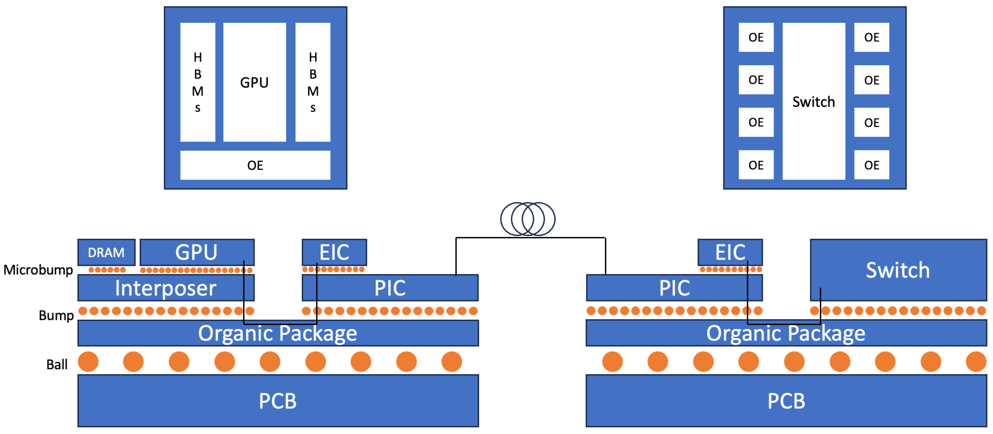
Co-packaged optics represents a fundamental shift in how optical interconnects are integrated into high-performance computing systems. The concept involves moving the optical I/O functionality from front-panel pluggable modules directly onto the same package or substrate as the main electronic IC, such as a network switch ASIC or a GPU, as shown in Figure 9. By co-integrating the photonic and electronic chiplets, the electrical distance that high-speed signals must travel is reduced from tens of centimeters across a PCB to mere millimeters or microns on the package substrate [105,106,107].
This architectural change is driven primarily by the immense power consumption of modern data centers. In a traditional pluggable architecture, a significant portion of the system power (~15 pJ/bit) is consumed by the SerDes (Serializer/Deserializer) circuits needed to drive the long, lossy copper traces to the front panel. CPO promises to slash this interconnect power to <5 pJ/bit, a critical step for enabling the terabit-per-second switches and AI accelerators of the future. However, this approach introduces significant new challenges in thermal management (as the hot ASIC is now next to the temperature-sensitive PIC), manufacturing yield, testing, and field serviceability.

6.2.2. Inverse Design and Artificial Intelligence (AI)

The increasing complexity of photonic devices is driving a revolution in design methodology. The traditional approach, which relies on human intuition and parameter sweeps of known structures, is often too slow and suboptimal for creating the novel components required for next-generation systems. Inverse design is a new paradigm that flips this process on its head [108,109]. Instead of starting with a structure, the designer specifies a desired optical function (a figure of merit), and an optimization algorithm explores a vast design space to generate a device topology that best achieves that function [110].
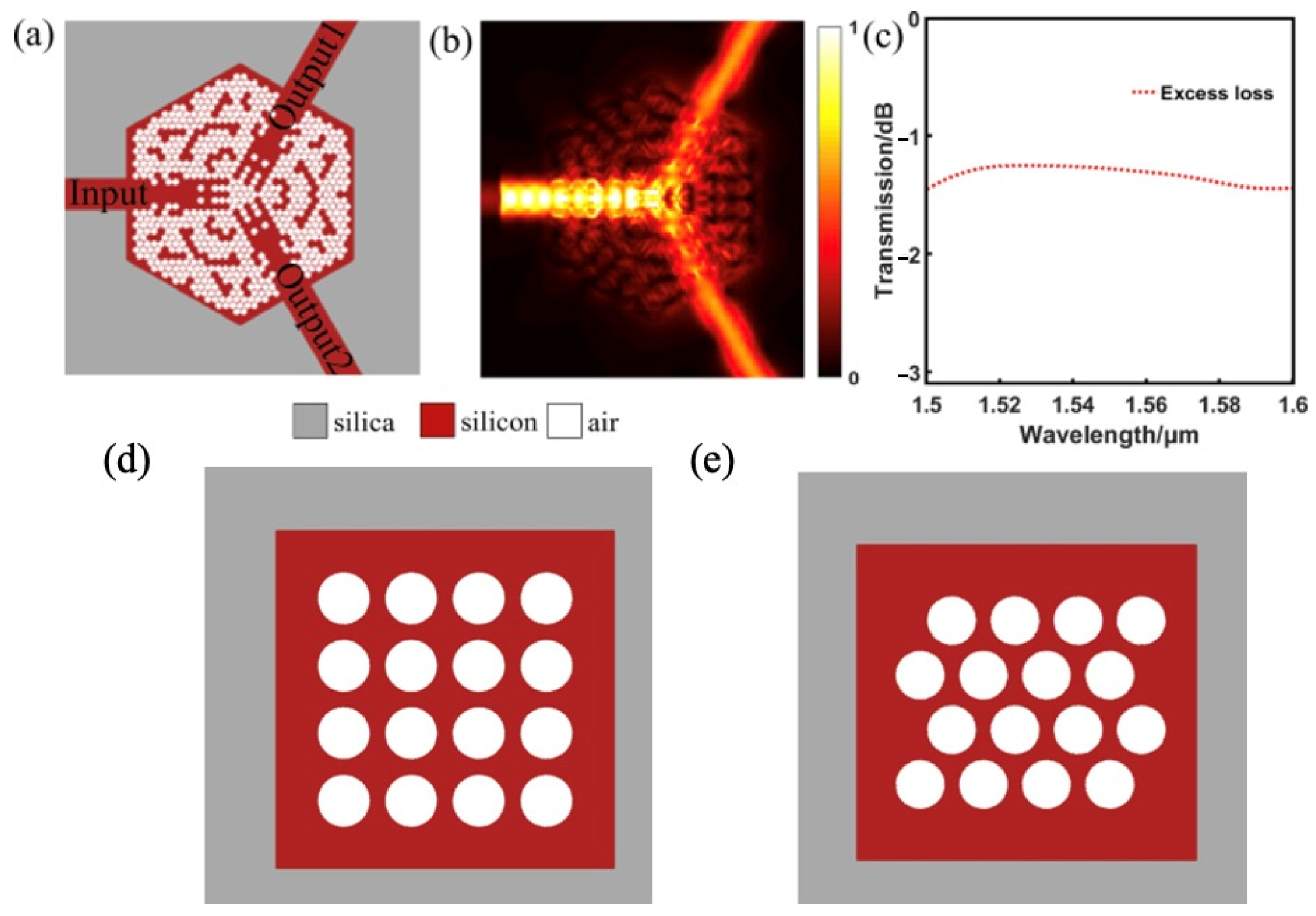
These algorithms, such as topology optimization (TO) or genetic algorithms (GA), often produce non-intuitive, free-form, or “pixelated” structures that can significantly outperform their conventional counterparts, as shown in Figure 10. This has led to breakthroughs in creating ultra-compact and highly efficient devices like splitters and grating couplers [111].
Complementing inverse design, artificial intelligence and machine learning models are being used to accelerate the design cycle even further [112]. Deep neural networks (DNNs) can be trained on simulation data to act as ultra-fast surrogates for computationally expensive electromagnetic solvers. This allows for the rapid prediction of a device’s performance, enabling vast optimizations that would otherwise be intractable. A key challenge that remains is the “black-box” nature of these methods; understanding the underlying physics of the novel structures they produce is an active area of research.

6.2.3. New Frontiers: Quantum and Sensing

The maturation of the silicon photonics platform is enabling its application in entirely new domains beyond communications. Quantum technologies represent a significant frontier, with silicon photonics emerging as a leading platform for building photonic quantum computers. The ability to fabricate large-scale, complex interferometric circuits with high stability and low loss on a chip is ideal for manipulating photonic qubits [113,114]. Photons are robust qubits, resilient to decoherence, and can be operated at room temperature. The scalability and manufacturability offered by CMOS foundries are a major advantage for constructing the future’s million-qubit, fault-tolerant systems.
Another key area is advanced sensing, where the high sensitivity of photonic devices to their environment is being leveraged for a new generation of miniaturized, low-cost, and high-performance sensors [115]. Applications include biosensing [116], where high-Q microring resonators are used as highly sensitive label-free biosensors to detect the presence of proteins, viruses, or DNA by measuring minute changes in the refractive index of their surroundings. Spectroscopy is also enabled on-chip through miniaturized Fourier-transform spectrometers (FTS) or AWGs, used for chemical analysis and gas sensing, particularly in the mid-infrared range [117]. Furthermore, LiDAR systems for autonomous vehicles and robotics are being developed using PICs to build solid-state systems that steer laser beams without any moving parts [118].
These emerging trends are not developing in isolation but are part of a virtuous cycle. The demand for more computational power for AI is a primary driver for CPO. The complexity of CPO systems necessitates the use of AI-driven inverse design tools. The resulting ability to design and fabricate highly complex, integrated systems then opens the door to revolutionary applications like large-scale quantum processors and multi-analyte sensor arrays, which in turn create new demands, further accelerating the entire field.

7. Conclusions

7.1. Synthesis of Key Advancements

The field of passive silicon photonics has undergone a period of transformative growth, evolving from a promising academic research area into a mature, industrialized technology. This review has charted the remarkable progress across its foundational components. We have witnessed the propagation loss of optical waveguides plummet from the dB/cm to the dB/m regime, a thousand-fold improvement driven by advances in rib waveguide architectures, ultra-pure silicon nitride films, and novel fabrication techniques like the Damascene process. This ultra-low loss has been the direct enabler for resonant devices, such as microring resonators, to achieve extraordinary quality factors in the tens of millions, unlocking new possibilities in filtering, sensing, and nonlinear optics.
Simultaneously, the critical interfaces to and within the chip have been perfected. Both grating couplers and edge couplers have converged on near-unity coupling efficiencies, effectively erasing a long-standing performance trade-off and giving system architects greater flexibility in packaging and testing strategies. On-chip splitters and routers, once limited by the simple geometries of Y-branches and directional couplers, are now sophisticated components engineered for broadband, low-loss, and fabrication-tolerant operation through the use of mode evolution principles and sub-wavelength grating metamaterials.
Underpinning all these device-level advancements is the maturation of the global fabrication ecosystem. The multi-project wafer (MPW) model has successfully democratized access to state-of-the-art manufacturing, fostering a vibrant community of innovation among universities and fabless design houses. Major commercial and research foundries now offer robust, well-characterized process design kits (PDKs) that include not only silicon but also co-integrated materials like silicon nitride and germanium, alongside advanced packaging solutions, providing a clear and reliable path from concept to high-volume production.

7.2. Concluding Perspective on the Field’s Trajectory

Looking at the trajectory of the field, it is clear that silicon photonics is successfully navigating the transition from a focus on optimizing individual component performance to a focus on system-level integration, manufacturability, and robustness. The central questions are evolving from “Can we build a high-performance device?” to “Can we integrate, package, test, and scale these complex systems reliably and cost-effectively?” This shift is indicative of a technology reaching industrial maturity.
The convergence of several powerful trends—the insatiable demand for bandwidth from AI, the architectural shift towards co-packaged optics, the paradigm change in design methodology brought by AI-driven tools, and the expansion into new application frontiers like quantum computing and advanced sensing—creates a powerful, self-reinforcing cycle of innovation. As these elements co-evolve, they accelerate the capabilities of the platform at an exponential rate. Silicon photonics is therefore not merely an incremental improvement over copper interconnects; it is a foundational enabling technology poised to follow a similar trajectory of impact and integration as the electronic integrated circuit industry. It is cementing its role as the essential hardware backbone for the data-intensive, intelligent, and quantum-aware world of the 21st century.

Author Contributions

Resources and Original Draft, and Review, Q.L. and Y.B.; Writing—Review and Editing, J.X.; Project Administration and Supervision, Q.L. All authors contributed to data analysis and manuscript writing. All authors have read and agreed to the published version of the manuscript.

Funding

This research received no external funding.

Institutional Review Board Statement

Not applicable.

Informed Consent Statement

Not applicable.

Data Availability Statement

The data related to the paper are available from the corresponding authors upon reasonable request.

Conflicts of Interest

The authors declare no conflicts of interest.

References

  1. Udkar, S. Harnessing Photonic Computing for Next-Generation CPUs and GPUs in High-Performance Computing. Int. J. Emerg. Trends Comput. Sci. Inf. Technol. 2024, 5, 23–36. [Google Scholar] [CrossRef]
  2. Wang, Z.; Xiao, Y.; Liao, K.; Li, T.; Song, H.; Chen, H.; Uddin, S.M.Z.; Mao, D.; Wang, F.; Zhou, Z.; et al. Metasurface on integrated photonic platform: From mode converters to machine learning. Nanophotonics 2022, 11, 3531–3546. [Google Scholar] [CrossRef] [PubMed]
  3. Ning, S.; Zhu, H.; Feng, C.; Gu, J.; Jiang, Z.; Ying, Z.; Midkiff, J.; Jain, S.; Hlaing, M.H.; Pan, D.Z.; et al. Photonic-Electronic Integrated Circuits for High-Performance Computing and AI Accelerators. J. Light. Technol. 2024, 42, 7834–7859. [Google Scholar] [CrossRef]
  4. Resch, M.M.; Gebert, J.; Hoppe, D. The Future of HPC and AI. In Proceedings of the 2025 International Conference on Intelligent Control, Computing and Communications (IC3), Mathura, India, 13–14 February 2025; pp. 897–904. [Google Scholar] [CrossRef]
  5. Margalit, N.; Xiang, C.; Bowers, S.M.; Bjorlin, A.; Blum, R.; Bowers, J.E. Perspective on the future of silicon photonics and electronics. Appl. Phys. Lett. 2021, 118, 220501. [Google Scholar] [CrossRef]
  6. Rahim, A.; Hermans, A.; Wohlfeil, B.; Petousi, D.; Kuyken, B.; Van Thourhout, D.; Baets, R.G. Taking silicon photonics modulators to a higher performance level: State-of-the-art and a review of new technologies. Adv. Photonics 2021, 3, 024003. [Google Scholar] [CrossRef]
  7. Hirokawa, T.; Bian, Y.; Giewont, K.; Aboketaf, A.; Chandran, S.; Cho, J.-K.; Chowdhury, Z.; Lee, W.S.; Liu, Q.; Sharma, P.; et al. Latest progress and challenges in 300 mm monolithic silicon photonics manufacturing. In Proceedings of the Optical Fiber Communication Conference, San Diego, CA, USA, 24–28 March 2024; Optica Publishing Group: Washington, DC, USA, 2024; p. Th3H-2. [Google Scholar] [CrossRef]
  8. Shekhar, S.; Bogaerts, W.; Chrostowski, L.; Bowers, J.E.; Hochberg, M.; Soref, R.; Shastri, B.J. Roadmapping the next generation of silicon photonics. Nat. Commun. 2024, 15, 751. [Google Scholar] [CrossRef] [PubMed]
  9. Dhote, C.; Singh, A.; Kumar, S. Silicon Photonics Sensors for Biophotonic Applications—A Review. IEEE Sens. J. 2022, 22, 18228–18239. [Google Scholar] [CrossRef]
  10. Debnath, K.; Arimoto, H.; Husain, M.K.; Prasmusinto, A.; Al-Attili, A.; Petra, R.; Chong, H.M.H.; Reed, G.T.; Saito, S. Low-Loss Silicon Waveguides and Grating Couplers Fabricated Using Anisotropic Wet Etching Technique. Front. Mater. 2016, 3, 10. [Google Scholar] [CrossRef]
  11. Dong, P.; Qian, W.; Liao, S.; Liang, H.; Kung, C.-C.; Feng, N.-N.; Shafiiha, R.; Fong, J.; Feng, D.; Krishnamoorthy, A.V.; et al. Low loss shallow-ridge silicon waveguides. Opt. Express 2010, 18, 14474–14479. [Google Scholar] [CrossRef]
  12. Vlasov, Y.A.; McNab, S.J. Losses in single-mode silicon-on-insulator strip waveguides and bends. Opt. Express 2004, 12, 1622–1631. [Google Scholar] [CrossRef]
  13. Gould, M.; Pomerene, A.; Hill, C.; Ocheltree, S.; Zhang, Y.; Baehr-Jones, T.; Hochberg, M. Ultra-thin silicon-on-insulator strip waveguides and mode couplers. Appl. Phys. Lett. 2012, 101, 221106. [Google Scholar] [CrossRef]
  14. Wu, S.; Mu, X.; Cheng, L.; Mao, S.; Fu, H.Y. State-of-the-Art and Perspectives on Silicon Waveguide Crossings: A Review. Micromachines 2020, 11, 326. [Google Scholar] [CrossRef] [PubMed]
  15. Wei, J.; Zhu, C.; Yu, Y.; Wang, R.; Yu, S. Low-loss silicon waveguide and an ultrahigh-Q silicon microring resonator in the 2 µm wave band. Opt. Lett. 2024, 49, 3271–3274. [Google Scholar] [CrossRef]
  16. Tran, M.A.; Huang, D.; Komljenovic, T.; Peters, J.; Malik, A.; Bowers, J.E. Ultra-Low-Loss Silicon Waveguides for Heterogeneously Integrated Silicon/III-V Photonics. Appl. Sci. 2018, 8, 1139. [Google Scholar] [CrossRef]
  17. Thander, A.K. Numerical methods for modal analysis in optical rib waveguide structures: A review. J. Opt. 2024, 1–7. [Google Scholar] [CrossRef]
  18. Huang, H.; Liu, K.; Qi, B.; Sorger, V.J. Re-Analysis of Single-Mode Conditions for Silicon Rib Waveguides at 1550 nm Wavelength. J. Light. Technol. 2016, 34, 3811–3817. [Google Scholar] [CrossRef]
  19. Li, Z.; Fan, Z.; Zhou, J.; Cong, Q.; Zeng, X.; Zhang, Y.; Jia, L. Process Development of Low-Loss LPCVD Silicon Nitride Waveguides on 8-Inch Wafer. Appl. Sci. 2023, 13, 3660. [Google Scholar] [CrossRef]
  20. Li, D.; Li, B.; Tang, B.; Zhang, P.; Yang, Y.; Liu, R.; Xie, L.; Li, Z. Broadband Silicon Nitride Power Splitter Based on Bent Directional Couplers with Low Thermal Sensitivity. Micromachines 2022, 13, 559. [Google Scholar] [CrossRef] [PubMed]
  21. Chandran, S.; Bian, Y.; Lee, W.S.; Abumazwed, A.; Liu, N.; Xu, L.; Ding, H.; Aboketaf, A.; Rakowski, M.; Dezfulian, K.; et al. High performance silicon nitride passive optical components on monolithic silicon photonics platform. In Proceedings of the Optical Fiber Communication Conference, San Diego, CA, USA, 24–28 March 2024; Optica Publishing Group: Washington, DC, USA, 2024; p. Th3H-4. [Google Scholar] [CrossRef]
  22. Bauters, J.F.; Heck, M.J.R.; John, D.D.; Barton, J.S.; Bruinink, C.M.; Leinse, A.; Heideman, R.G.; Blumenthal, D.J.; Bowers, J.E. Planar waveguides with less than 0.1 dB/m propagation loss fabricated with wafer bonding. Opt. Express 2011, 19, 24090–24101. [Google Scholar] [CrossRef]
  23. Ji, X.; Wang, R.N.; Liu, Y.; Riemensberger, J.; Qiu, Z.; Kippenberg, T.J. Efficient mass manufacturing of high-density, ultra-low-loss Si3N4 photonic integrated circuits. Optica 2024, 11, 1397–1407. [Google Scholar] [CrossRef]
  24. Ji, X.; Okawachi, Y.; Gil-Molina, A.; Corato-Zanarella, M.; Roberts, S.; Gaeta, A.L.; Lipson, M. Ultra-Low-Loss Silicon Nitride Photonics Based on Deposited Films Compatible with Foundries. Laser Photonics Rev. 2023, 17, 2200544. [Google Scholar] [CrossRef]
  25. Fahrenkopf, N.M.; McDonough, C.; Leake, G.L.; Su, Z.; Timurdogan, E.; Coolbaugh, D.D. The AIM Photonics MPW: A Highly Accessible Cutting Edge Technology for Rapid Prototyping of Photonic Integrated Circuits. IEEE J. Sel. Top. Quantum Electron. 2019, 25, 8201406. [Google Scholar] [CrossRef]
  26. Carpenter, L.G.; van Niekerk, M.; Begović, A.; Sundaram, V.S.; Deenadayalan, V.; Palone, T.; Fanto, M.; Preble, S.; Baiocco, C.; Leake, G.L.; et al. Towards Low Propagation Losses in Active Photonic Multi-Project Wafer Runs. In Proceedings of the OSA Advanced Photonics Congress 2021, Washington, DC, USA, 26–29 July 2021; Optica Publishing Group: Washington, DC, USA, 2021; p. ITu3A.5. [Google Scholar] [CrossRef]
  27. Kim, E.; Carpenter, L.; Smith, A.M.; Tison, C.C.; Coleman, D.; Leake, G.; Fanto, M.; Rizzo, A.J.; García-Blanco, S.M.; Cheben, P. Ultra-low loss dispersion-engineered silicon nitride waveguides on 300 mm wafers. In Proceedings of the Integrated Optics: Devices, Materials, and Technologies XXIX, San Francisco, CA, USA, 27–30 January 2025; SPIE: Bellingham, DC, USA, 2025; pp. 271–277. [Google Scholar] [CrossRef]
  28. Pfeiffer, M.H.P.; Herkommer, C.; Liu, J.; Morais, T.; Zervas, M.; Geiselmann, M.; Kippenberg, T.J. Photonic Damascene Process for Low-Loss, High-Confinement Silicon Nitride Waveguides. IEEE J. Sel. Top. Quantum Electron. 2018, 24, 6101411. [Google Scholar] [CrossRef]
  29. Liu, J.; Huang, G.; Wang, R.N.; He, J.; Raja, A.S.; Liu, T.; Engelsen, N.J.; Kippenberg, T.J. High-yield, wafer-scale fabrication of ultralow-loss, dispersion-engineered silicon nitride photonic circuits. Nat. Commun. 2021, 12, 2236. [Google Scholar] [CrossRef]
  30. Luque-González, J.M.; Sánchez-Postigo, A.; Hadij-ElHouati, A.; Ortega-Moñux, A.; Wangüemert-Pérez, J.G.; Schmid, J.H.; Cheben, P.; Molina-Fernández, Í.; Halir, R. A review of silicon subwavelength gratings: Building break-through devices with anisotropic metamaterials. Nanophotonics 2021, 10, 2765–2797. [Google Scholar] [CrossRef]
  31. Bock, P.J.; Cheben, P.; Schmid, J.H.; Lapointe, J.; Delâge, A.; Xu, D.-X.; Janz, S.; Densmore, A.; Hall, T.J. Subwavelength grating crossings for silicon wire waveguides. Opt. Express 2010, 18, 16146–16155. [Google Scholar] [CrossRef]
  32. Molina-Fernández, I.; Wangüemert-Perez, J.G.; Ortega-Moñuz, A.; Halir, R.; Rubio, J.d.O.; Sánchez-Postigo, A.; Luque-González, J.M.; Hadij-Elhouati, A.; Pereira-Martín, D.; Gonzalez-Andrade, D.; et al. Silicon subwavelength waveguiding devices. In Proceedings of the High Contrast Metastructures IX, San Francisco, CA, USA, 26 February 2020; SPIE: Bellingham, DC, USA, 2020; pp. 114–120. [Google Scholar] [CrossRef]
  33. Kazanskiy, N.L.; Butt, M.A.; Khonina, S.N. Silicon photonic devices realized on refractive index engineered subwavelength grating waveguides—A review. Opt. Laser Technol. 2021, 138, 106863. [Google Scholar] [CrossRef]
  34. Shi, Y.; Shao, B.; Zhang, Z.; Zhou, T.; Luo, F.; Xu, Y. Ultra-Broadband and Low-Loss Silicon-Based Power Splitter Based on Subwavelength Grating-Assisted Multimode Interference Structure. Photonics 2022, 9, 435. [Google Scholar] [CrossRef]
  35. Zhu, D.; Ye, H.; Liu, Y.; Li, J.; Wang, Y.; Yu, Z. Silicon subwavelength grating-assisted asymmetric directional coupler around 2 μm and its applications. Opt. Laser Technol. 2021, 136, 106789. [Google Scholar] [CrossRef]
  36. Chen, J.; Xiao, J. Ultracompact silicon-based polarization splitter and rotator based on asymmetric directional couplers with subwavelength gratings. JOSA B 2022, 39, 345–354. [Google Scholar] [CrossRef]
  37. Halir, R.; Bock, P.J.; Cheben, P.; Ortega-Moñux, A.; Alonso-Ramos, C.; Schmid, J.H.; Lapointe, J.; Xu, D.; Wangüemert-Pérez, J.G.; Molina-Fernández, Í.; et al. Waveguide sub-wavelength structures: A review of principles and applications. Laser Photonics Rev. 2015, 9, 25–49. [Google Scholar] [CrossRef]
  38. Sultan, A.; Khalil, M.; Mehravar, L.; Xu, C. Highly Efficient Polarization-Insensitive Grating Couplers on Thin-Film Lithium Niobate with an Integrated Gold Layer. Photonics 2025, 12, 111. [Google Scholar] [CrossRef]
  39. Cheng, L.; Mao, S.; Li, Z.; Han, Y.; Fu, H.Y. Grating Couplers on Silicon Photonics: Design Principles, Emerging Trends and Practical Issues. Micromachines 2020, 11, 666. [Google Scholar] [CrossRef]
  40. Tahara, N.; Nawa, S.; Taira, R.; Suyama, S.; Hirotani, K.; Kamata, M.; Maegami, Y.; Tsuchizawa, T.; Yamamoto, N.; Yamada, K.; et al. High efficiency silicon photonics grating coupler compatible to standard foundry service. In Proceedings of the Silicon Photonics XX, San Francisco, CA, USA, 28–30 January 2025; SPIE: Bellingham, DC, USA, 2025; pp. 57–65. [Google Scholar] [CrossRef]
  41. Cheng, H.; Wu, J.; Wang, Y.; Ran, C.; Li, H.; Wang, Y.; Li, Y.; Zhang, S.; Wang, C.; Yang, J. Ultra-Compact, High-Efficiency Vertical Meta-Grating Couplers for Meta-Photonic Integrated Circuits. Nanomaterials 2025, 15, 583. [Google Scholar] [CrossRef]
  42. Zhou, W.; Lu, K.; Kang, S.; Wu, X.; Tong, Y. Efficient Polarization-Diversity Grating Coupler With Multipolar Radiation Mode Enhancement. IEEE Photonics J. 2025, 17, 7100206. [Google Scholar] [CrossRef]
  43. Korček, R.; Fraser, W.; Wilmart, Q.; Quiroz, D.M.; Litvik, J.; Zubor, L.; Krehel, T.; Edmond, S.; Milanizadeh, M.; Schmid, J.H.; et al. High-efficiency off-chip grating couplers for silicon nitride photonics. In Proceedings of the Integrated Optics: Devices, Materials, and Technologies XXVIII, San Francisco, CA, USA, 29 January–1 February 2024; SPIE: Bellingham, DC, USA, 2024; pp. 41–45. [Google Scholar] [CrossRef]
  44. Wan, Y.; Zhang, Y.; Wang, J. O-band low loss and polarization insensitivity bilayer and double-tip edge coupler. Adv. Photonics Nexus 2025, 4, 026004. [Google Scholar] [CrossRef]
  45. Ai, X.; Xuan, M.W.; Zhang, Y.; Hsu, W.-L.; Veilleux, S.; Dagenais, M. Broadband high coupling efficiency edge coupler with low polarization-dependence on the silicon-nitride platform. Opt. Express 2025, 33, 16253–16262. [Google Scholar] [CrossRef] [PubMed]
  46. Liu, M.; Zhang, T.; Xu, B.; Zhang, Y.; Du, J.; Sun, J.; Wang, J. High-efficiency bident edge coupler based on thin film lithium niobate. Opt. Express 2025, 33, 16338–16349. [Google Scholar] [CrossRef]
  47. Zhang, T.; Li, J.; Li, M.; Liu, J. Design and Optimization of a High-Efficiency 3D Multi-Tip Edge Coupler Based Lithium Niobate on Insulator Platform. Photonics 2024, 11, 134. [Google Scholar] [CrossRef]
  48. Chen, B.; Ruan, Z.; Wang, M.; Gong, S.; Liu, L. High-performance and fabrication-tolerant edge coupler on thin film lithium niobate based on a three-dimensional inverse taper. APL Photonics 2024, 9, 116111. [Google Scholar] [CrossRef]
  49. Bian, Y.; Hirokawa, T.; Karra, V.; Dasgupta, A.; Lee, W.S.; Aboketaf, A.; Afzal, F.; Sporer, R.; Nummy, K.; Giewont, K.; et al. Monolithically integrated self-aligned SiN edge coupler with <0.6/0.8 dB TE/TM insertion loss, <−39 dB back reflection and >520 mW high-power handling capability. In Proceedings of the Optical Fiber Communication Conference (OFC) 2023, San Diego, CA, USA, 5–9 March 2023; Optica Publishing Group: Washington, DC, USA, 2023; p. M3C.3. [Google Scholar] [CrossRef]
  50. Marchetti, R.; Lacava, C.; Carroll, L.; Gradkowski, K.; Minzioni, P. Coupling strategies for silicon photonics integrated chips [Invited]. Photonics Res. 2019, 7, 201–239. [Google Scholar] [CrossRef]
  51. Xu, Y.; Tian, Z.; Meng, X.; Chai, Z. Methods and applications of on-chip beam splitting: A review. Front. Phys. 2022, 10, 985208. [Google Scholar] [CrossRef]
  52. Han, L.; Kuo, B.P.-P.; Alic, N.; Radic, S. Ultra-broadband multimode 3dB optical power splitter using an adiabatic coupler and a Y-branch. Opt. Express 2018, 26, 14800–14809. [Google Scholar] [CrossRef]
  53. Krutov, I.A.; Saygin, M.Y.; Dyakonov, I.V.; Kulik, S.P. Optimized low-loss integrated photonics silicon-nitride Y-branch splitter. AIP Conf. Proc. 2020, 2241, 020027. [Google Scholar] [CrossRef]
  54. Lv, D.; Wu, L.; Liu, C.; Li, A.; Wang, R.; Wu, A. Broadband and Low-Loss Silicon Photonic Directional Coupler for Signal Power Tapping on the 3 μm SOI Waveguide Platform. Photonics 2023, 10, 776. [Google Scholar] [CrossRef]
  55. Frishman, A.; Malka, D. An Optical 1×4 Power Splitter Based on Silicon–Nitride MMI Using Strip Waveguide Structures. Nanomaterials 2023, 13, 2077. [Google Scholar] [CrossRef] [PubMed]
  56. Taha, A.M.; Chandran, S.; Viegas, J.; Bian, Y.; Rakowski, M.; Augur, R.; Jacob, A.; Dahlem, M.S. Compact MMI-Based AWGs in a Scalable Monolithic Silicon Photonics Platform. IEEE Photonics J. 2021, 13, 6600306. [Google Scholar] [CrossRef]
  57. Xu, L.; Chandran, S.; Bian, Y.; Liu, N.; Abumazwed, A.; Lee, W.S.; Zhang, J.; Deptuck, D.; Rakowski, M.; Krishnamoorthy, S.; et al. Low-loss SiN 2 × 2 MMI 50/50 Couplers for Monolithically Integrated Silicon Photonics. In Proceedings of the CLEO 2023, San Jose, CA, USA, 7–12 May 2023; Optica Publishing Group: Washington, DC, USA, 2023; p. JW2A.86. [Google Scholar] [CrossRef]
  58. Vilas, J.; de Cabo, R.F.; Olivares, I.; González-Andrade, D.; Velasco, A.V.; Dias-Ponte, A. Low-Loss Directional Coupler for the C, L and U Bands Based on Subwavelength Gratings. IEEE Photonics Technol. Lett. 2023, 35, 1331–1334. [Google Scholar] [CrossRef]
  59. Yao, Z.; Wu, K.; Tan, B.X.; Wang, J.; Li, Y.; Zhang, Y.; Poon, A.W. Integrated Silicon Photonic Microresonators: Emerging Technologies. IEEE J. Sel. Top. Quantum Electron. 2018, 24, 5900324. [Google Scholar] [CrossRef]
  60. Bogaerts, W.; De Heyn, P.P.; Van Vaerenbergh, T.T.; De Vos, K.K.; Selvaraja, S.K.; Claes, T.T.; Dumon, P.; Bienstman, P.; Van Thourhout, D.D.; Baets, R.R. Silicon microring resonators. Laser Photonics Rev. 2012, 6, 47–73. [Google Scholar] [CrossRef]
  61. Van, V. Optical Microring Resonators: Theory, Techniques, and Applications; CRC Press: Boca Raton, FL, USA, 2016. [Google Scholar] [CrossRef]
  62. Nijem, J.; Naiman, A.; Zektzer, R.; Frydendahl, C.; Mazurski, N.; Levy, U. High-Q and high finesse silicon microring resonator. Opt. Express 2024, 32, 7896–7906. [Google Scholar] [CrossRef] [PubMed]
  63. Xuan, Y.; Liu, Y.; Varghese, L.T.; Metcalf, A.J.; Xue, X.; Wang, P.-H.; Han, K.; Jaramillo-Villegas, J.A.; Al Noman, A.; Wang, C.; et al. High-Q silicon nitride microresonators exhibiting low-power frequency comb initiation. Optica 2016, 3, 1171–1180. [Google Scholar] [CrossRef]
  64. Cui, S.; Cao, K.; Yu, Y.; Zhang, X. Ultra-high-Q racetrack microring based on silicon-nitride. arXiv 2022, arXiv:2209.01097. [Google Scholar] [CrossRef]
  65. Puckett, M.W.; Liu, K.; Chauhan, N.; Zhao, Q.; Jin, N.; Cheng, H.; Wu, J.; Behunin, R.O.; Rakich, P.T.; Nelson, K.D.; et al. 422 Million intrinsic quality factor planar integrated all-waveguide resonator with sub-MHz linewidth. Nat. Commun. 2021, 12, 934. [Google Scholar] [CrossRef]
  66. Perestjuk, M.; Armand, R.; Campos, M.G.S.; Ferhat, L.; Reboud, V.; Bresson, N.; Hartmann, J.-M.; Mathieu, V.; Ren, G.; Boes, A.; et al. One million quality factor integrated ring resonators in the mid-infrared. Nanophotonics 2025, 14, 1009–1015. [Google Scholar] [CrossRef]
  67. Liu, X.; Ruan, Z.; Sun, S.; Guo, C.; Chen, K.; Zhu, N.; Liu, L. Sharp bend and large FSR ring resonator based on the free-form curves on a thin-film lithium niobate platform. Opt. Express 2024, 32, 9433–9441. [Google Scholar] [CrossRef]
  68. Ouyang, B.; Xing, Y.; Bogaerts, W.; Caro, J. Silicon ring resonators with a free spectral range robust to fabrication variations. Opt. Express 2019, 27, 38698–38707. [Google Scholar] [CrossRef]
  69. Marques, A.; Cabrita, P.; Carvalhais, M.; Novo, C.; Lima, M.; Rodrigues, F.; Teixeira, A. Simulation and Experimental Validation of a Silicon Photonics Ring Assisted Mach-Zehnder Interferometer Filter. In Proceedings of the 13th International Conference on Photonics, Optics and Laser Technology, Porto, Portugal, 22–24 February 2025; pp. 147–151. [Google Scholar] [CrossRef]
  70. Chen, H.-Z.; Ho, K.-L.; Wang, P.-H. High-Extinction Photonic Filters by Cascaded Mach–Zehnder Interferometer-Coupled Resonators. Photonics 2024, 11, 1055. [Google Scholar] [CrossRef]
  71. Hiraki, T.; Fukuda, H.; Yamada, K.; Yamamoto, T. Small Sensitivity to Temperature Variations of Si-Photonic Mach–Zehnder Interferometer Using Si and SiN Waveguides. Front. Mater. 2015, 2, 26. [Google Scholar] [CrossRef]
  72. Yuan, S.; Feng, J.; Yu, Z.; Chen, J.; Liu, H.; Chen, Y.; Guo, S.; Huang, F.; Akimoto, R.; Zeng, H. Silicon Nanowire-Assisted High Uniform Arrayed Waveguide Grating. Nanomaterials 2023, 13, 182. [Google Scholar] [CrossRef]
  73. Stanton, E.J.; Spott, A.; Davenport, M.L.; Volet, N.; Bowers, J.E. Low-loss arrayed waveguide grating at 760 nm. Opt. Lett. 2016, 41, 1785–1788. [Google Scholar] [CrossRef]
  74. Stanton, E.J.; Volet, N.; Bowers, J.E. Low-loss arrayed waveguide grating at 2.0 µm. In Proceedings of the Conference on Lasers and Electro-Optics (2017), San Jose, CA, USA, 14–19 May 2017; Optica Publishing Group: Washington, DC, USA, 2017; p. STh1M.7. [Google Scholar] [CrossRef]
  75. Liu, Y.; Wang, X.; Yao, Y.; Du, J.; Song, Q.; Xu, K. Silicon photonic arrayed waveguide grating with 64 channels for the 2 µm spectral range. Opt. Lett. 2022, 47, 1186–1189. [Google Scholar] [CrossRef] [PubMed]
  76. Siew, S.Y.; Li, B.; Gao, F.; Zheng, H.Y.; Zhang, W.; Guo, P.; Xie, S.W.; Song, A.; Dong, B.; Luo, L.W.; et al. Review of Silicon Photonics Technology and Platform Development. J. Light. Technol. 2021, 39, 4374–4389. [Google Scholar] [CrossRef]
  77. Lim, A.E.-J.; Song, J.; Fang, Q.; Li, C.; Tu, X.; Duan, N.; Chen, K.K.; Tern, R.P.-C.; Liow, T.-Y. Review of silicon photonics foundry efforts. IEEE J. Sel. Top. Quantum Electron. 2013, 20, 405–416. [Google Scholar] [CrossRef]
  78. Absil, P.P.; De Heyn, P.; Chen, H.; Verheyen, P.; Lepage, G.; Pantouvaki, M.; De Coster, J.; Khanna, A.; Drissi, Y.; Van Thourhout, D.; et al. Imec iSiPP25G silicon photonics: A robust CMOS-based photonics technology platform. In Proceedings of the Silicon Photonics X, San Francisco, CA, USA, 7–12 February 2015; SPIE: Bellingham, DC, USA, 2015; pp. 166–171. [Google Scholar] [CrossRef]
  79. Ferraro, F.J.; De Heyn, P.; Kim, M.; Rajasekaran, N.; Berciano, M.; Muliuk, G.; Bode, D.; Lepage, G.; Janssen, S.; Magdziak, R.; et al. Imec silicon photonics platforms: Performance overview and roadmap. In Proceedings of the Next-Generation Optical Communication: Components, Sub-Systems, and Systems XII, San Francisco, CA, USA, 31 January–2 February 2023; SPIE: Bellingham, DC, USA, 2023; pp. 22–28. [Google Scholar] [CrossRef]
  80. Quack, N.; Takabayashi, A.Y.; Sattari, H.; Edinger, P.; Jo, G.; Bleiker, S.J.; Errando-Herranz, C.; Gylfason, K.B.; Niklaus, F.; Khan, U.; et al. Integrated silicon photonic MEMS. Microsyst. Nanoeng. 2023, 9, 27. [Google Scholar] [CrossRef]
  81. Roelkens, G.; Zhang, J.; Bogaert, L.; Billet, M.; Wang, D.; Pan, B.; Kruckel, C.J.; Soltanian, E.; Maes, D.; Vanackere, T.; et al. Micro-Transfer Printing for Heterogeneous Si Photonic Integrated Circuits. IEEE J. Sel. Top. Quantum Electron. 2023, 29, 8200414. [Google Scholar] [CrossRef]
  82. Sahrling, M.; Li, S.; Lee, F.; Rusu, S. TSMC in the Silicon Photonics Era—An electrical perspective. In Proceedings of the Optical Fiber Communication Conference (OFC) 2025, San Francisco, CA, USA, 30 March–3 April 2025; Optica Publishing Group: Washington, DC, USA, 2025; p. Tu3G.1. [Google Scholar] [CrossRef]
  83. Hsia, H.; Tsai, C.; Ting, K.; Kuo, F.; Lin, C.; Wang, C.; Hou, S.; Chiou, W.; Yu, D.C. Heterogeneous Integration of a Compact Universal Photonic Engine for Silicon Photonics Applications in HPC. In Proceedings of the 2021 IEEE 71st Electronic Components and Technology Conference (ECTC), San Diego, CA, USA, 1 June–4 July 2021; pp. 263–268. [Google Scholar] [CrossRef]
  84. Lu, H.-Y.; Tang, C.-T.; Chen, C.-H.; Tan, B.-X.; Liu, W.-K.; Chiang, H.-Y.; Tsai, S.-Y.; Hsieh, T.-L.; Mao, W.-J.; Lo, W.-T.; et al. Low-loss High-uniformity Silicon Nitride Optical Building Blocks Integrated on Silicon Photonics Platform. In Proceedings of the 2025 Optical Fiber Communications Conference and Exhibition (OFC), San Francisco, CA, USA, 30 March–3 April 2025; pp. 1–3. [Google Scholar] [CrossRef]
  85. Giewont, K.; Hu, S.; Peng, B.; Rakowski, M.; Rauch, S.; Rosenberg, J.C.; Sahin, A.; Stobert, I.; Stricker, A.; Nummy, K.; et al. 300-mm Monolithic Silicon Photonics Foundry Technology. IEEE J. Sel. Top. Quantum Electron. 2019, 25, 8200611. [Google Scholar] [CrossRef]
  86. Bian, Y.; Hirokawa, T.; Lee, W.S.; Chandran, S.; Giewont, K.; Aboketaf, A.; Liu, Q.; Sporer, R.; Rakowski, M.; Dezfulian, K.; et al. 300-mm monolithic CMOS silicon photonics foundry technology. In Proceedings of the CLEO: Applications and Technology 2024, Charlotte, NC, USA, 5–10 May 2024; p. ATu3H-1. [Google Scholar]
  87. Littlejohns, C.G.; Rowe, D.J.; Du, H.; Li, K.; Zhang, W.; Cao, W.; Bucio, T.D.; Yan, X.; Banakar, M.; Tran, D.; et al. CORNERSTONE’s Silicon Photonics Rapid Prototyping Platforms: Current Status and Future Outlook. Appl. Sci. 2020, 10, 8201. [Google Scholar] [CrossRef]
  88. Tossoun, B.; Xiao, X.; Cheung, S.; Yuan, Y.; Peng, Y.; Srinivasan, S.; Giamougiannis, G.; Huang, Z.; Singaraju, P.; London, Y.; et al. Large-Scale Integrated Photonic Device Platform for Energy-Efficient AI/ML Accelerators. IEEE J. Sel. Top. Quantum Electron. 2025, 31, 8200326. [Google Scholar] [CrossRef]
  89. Liu, Q.; Aboketaf, A.; Pal, S.; Mosleh, S.; Banihashemian, S.F.; Pavadai, S.; Lee, J.-C.; Bian, Y.; Gong, M.; Orner, B.; et al. High-Power Micro-Ring Modulator and Multi-Channel Coupled Ring Resonator for WDM Design on a 300-mm Monolithic Foundry Platform. In Proceedings of the Optical Fiber Communication Conference (OFC) 2024, San Diego, CA, USA, 24–28 March 2024; Optica Publishing Group: Washington, DC, USA, 2024; p. M3A.2. [Google Scholar] [CrossRef]
  90. Bian, Y.; Aboketaf, A.; Lee, W.S.; Chandran, S.; Huante-Ceron, E.; Najafi, A.; Villafranca, A.; Shiran, H.; Holt, J.; Afzal, F.; et al. Monolithically integrated high-performance Ge-on-Si PIN photodetectors with nearly 60 GHz EO bandwidth, 0.95 A/W re-sponsivity, <30 nA dark current and −36 dB optical return loss enabled by Ge shape optimization. In Proceedings of the Optical Fiber Communication Conference (OFC) 2025, San Francisco, CA, USA, 30 March–3 April 2025; Optica Publishing Group: Washington, DC, USA, 2025; p. Th3E.6. [Google Scholar] [CrossRef]
  91. Bian, Y.; Ramachandran, K.; Wu, Z.-J.; Hedrick, B.; Dezfulian, K.K.; Houghton, T.; Nummy, K.; Fisher, D.; Hirokawa, T.; Donegan, K.; et al. 3D Integrated Laser Attach Technology on a 300-mm Monolithic CMOS Silicon Photonics Platform. IEEE J. Sel. Top. Quantum Electron. 2023, 29, 8200519. [Google Scholar] [CrossRef]
  92. Xiang, C.; Jin, W.; Huang, D.; Tran, M.A.; Guo, J.; Wan, Y.; Xie, W.; Kurczveil, G.; Netherton, A.M.; Liang, D.; et al. High-Performance Silicon Photonics Using Heterogeneous Integration. IEEE J. Sel. Top. Quantum Electron. 2022, 28, 8200515. [Google Scholar] [CrossRef]
  93. Xiang, C.; Liu, J.; Guo, J.; Chang, L.; Wang, R.N.; Weng, W.; Peters, J.; Xie, W.; Zhang, Z.; Riemensberger, J.; et al. Laser soliton microcombs heterogeneously integrated on silicon. Science 2021, 373, 99–103. [Google Scholar] [CrossRef]
  94. Liu, Y.; Qiu, Z.; Ji, X.; Bancora, A.; Lihachev, G.; Riemensberger, J.; Wang, R.N.; Voloshin, A.; Kippenberg, T.J. A fully hybrid integrated erbium-based laser. Nat. Photonics 2024, 18, 829–835. [Google Scholar] [CrossRef]
  95. Elshaari, A.W.; Pernice, W.; Srinivasan, K.; Benson, O.; Zwiller, V. Hybrid integrated quantum photonic circuits. Nat. Photonics 2020, 14, 285–298. [Google Scholar] [CrossRef]
  96. Dai, D.; Liu, L.; Gao, S.; Xu, D.-X.; He, S. Polarization management for silicon photonic integrated circuits. Laser Photonics Rev. 2013, 7, 303–328. [Google Scholar] [CrossRef]
  97. Bian, Y.; Lee, W.S.; Chandran, S.; Hirokawa, T.; Sorbara, M.; Aboketaf, A.; Dezfulian, K.K.; Najafi, A.; Mosleh, S.; Banihashemian, F.; et al. Minimizing polarization dependent loss for monolithic silicon photonic components and receiver circuits. In Proceedings of the CLEO: Applications and Technology 2024, Charlotte, NC, USA, 5–10 May 2024; Optica Publishing Group: Washington, DC, USA, 2024; p. AM2J-5. [Google Scholar] [CrossRef]
  98. Bian, Y.; Lee, W.S.; Chandran, S.; Hirokawa, T.; Sorbara, M.; Aboketaf, A.; Dezfulian, K.K.; Najafi, A.; Mosleh, S.; Banihashemian, F.; et al. Towards polarization insensitive photonic integrated circuits: Polarization dependent loss reduction of CMOSintegrated monolithic SiPh components. In Proceedings of the 2024 Optical Fiber Communications Conference and Exhibition (OFC), San Diego, CA, USA, 24–28 March 2024; IEEE: New York, NY, USA, 2024; pp. 1–3. Available online: https://ieeexplore.ieee.org/abstract/document/10526737/ (accessed on 9 August 2025).
  99. Bian, Y.; Ding, H.; Aboketaf, A.; Karra, V.; Sorbara, M.; Hirokawa, T.; Mosleh, S.; Hedges, C.; Lee, W.S.; Chandran, S.; et al. Polarization mode dispersion in CMOS-integrated monolithic SiPh components: Simulations and experiments. In Proceedings of the 2023 Optical Fiber Communications Conference and Exhibition (OFC), San Diego, CA, USA, 5–9 March 2023; pp. 1–3. [Google Scholar] [CrossRef]
  100. Villegas, J.E.; Tamalampudi, S.R.; Rasras, M. High-speed polarization control in integrated silicon photonics. Opt. Express 2025, 33, 18477–18491. [Google Scholar] [CrossRef]
  101. Shahwar, D.; Yoon, H.H.; Akkanen, S.-T.; Li, D.; Muntaha, S.T.; Cherchi, M.; Aalto, T.; Sun, Z. Polarization management in silicon photonics. npj Nanophotonics 2024, 1, 35. [Google Scholar] [CrossRef]
  102. Pruessner, M.W.; Tyndall, N.F.; Stievater, T.H. MEMS-tunable polarization management in photonic integrated circuits. Opt. Express 2023, 31, 31316–31328. [Google Scholar] [CrossRef]
  103. O’Brien, P.; Carrol, L.; Eason, C.; Lee, J.S. Packaging of Silicon Photonic Devices. In Silicon Photonics III: Systems and Applications; Pavesi, L., Lockwood, D.J., Eds.; Springer: Berlin/Heidelberg, Germany, 2016; pp. 217–236. [Google Scholar] [CrossRef]
  104. Carroll, L.; Lee, J.-S.; Scarcella, C.; Gradkowski, K.; Duperron, M.; Lu, H.; Zhao, Y.; Eason, C.; Morrissey, P.; Rensing, M.; et al. Photonic Packaging: Transforming Silicon Photonic Integrated Circuits into Photonic Devices. Appl. Sci. 2016, 6, 426. [Google Scholar] [CrossRef]
  105. Tan, M.; Xu, J.; Liu, S.; Feng, J.; Zhang, H.; Yao, C.; Chen, S.; Guo, H.; Han, G.; Wen, Z.; et al. Co-packaged optics (CPO): Status, challenges, and solutions. Front. Optoelectron. 2023, 16, 1. [Google Scholar] [CrossRef] [PubMed]
  106. Lee, B.G.; Nedovic, N.; Greer, T.H.; Gray, C.T. Beyond CPO: A Motivation and Approach for Bringing Optics Onto the Silicon Interposer. J. Light. Technol. 2023, 41, 1152–1162. [Google Scholar] [CrossRef]
  107. Shen, X.; Chen, B.; Zhu, Y.; Shi, W. Silicon photonic integrated circuits and its application in data center. In Proceedings of the Seventh Symposium on Novel Photoelectronic Detection Technology and Applications, Kunming, China, 5–7 November 2020; SPIE: Bellingham, DC, USA, 2021; pp. 2110–2123. [Google Scholar] [CrossRef]
  108. Pira, L.; Antony, A.; Prathap, N.; Peace, D.; Romero, J. Enhanced Photonic Chip Design via Interpretable Machine Learning Techniques. arXiv 2025, arXiv:2505.09266. [Google Scholar] [CrossRef]
  109. Mao, S.; Cheng, L.; Zhao, C.; Khan, F.N.; Li, Q.; Fu, H.Y. Inverse Design for Silicon Photonics: From Iterative Optimization Algorithms to Deep Neural Networks. Appl. Sci. 2021, 11, 3822. [Google Scholar] [CrossRef]
  110. Shen, R.; Hong, B.; Ren, X.; Yang, F.; Chu, W.; Cai, H.; Huang, W. Recent progress on inverse design for integrated photonic devices: Methodology and applications. J. Nanophotonics 2024, 18, 010901. [Google Scholar] [CrossRef]
  111. Ma, H.; Huang, J.; Zhang, K.; Yang, J. Inverse-designed arbitrary-input and ultra-compact 1 × N power splitters based on high symmetric structure. Sci. Rep. 2020, 10, 11757. [Google Scholar] [CrossRef]
  112. Yang, K.Y.; Shirpurkar, C.; White, A.D.; Zang, J.; Chang, L.; Ashtiani, F.; Guidry, M.A.; Lukin, D.M.; Pericherla, S.V.; Yang, J.; et al. Multi-dimensional data transmission using inverse-designed silicon photonics and microcombs. Nat. Commun. 2022, 13, 7862. [Google Scholar] [CrossRef] [PubMed]
  113. Rad, H.A.; Ainsworth, T.; Alexander, R.N.; Altieri, B.; Askarani, M.F.; Baby, R.; Banchi, L.; Baragiola, B.Q.; Bourassa, J.E.; Chadwick, R.S.; et al. Scaling and networking a modular photonic quantum computer. Nature 2025, 638, 912–919. [Google Scholar] [CrossRef] [PubMed]
  114. Alexander, K.; Bahgat, A.; Benyamini, A.; Black, D.; Bonneau, D.; Burgos, S.; Burridge, B.; Cable, H.; Campbell, G.; Catalano, G.; et al. A manufacturable platform for photonic quantum computing. Nature 2025, 641, 876–883. [Google Scholar] [CrossRef] [PubMed]
  115. Jain, S.; Hlaing, M.H.; Fan, K.-C.; Midkiff, J.; Ning, S.; Feng, C.; Hsiao, P.-Y.; Camp, P.T.; Chen, R.T. Incubating advances in integrated photonics with emerging sensing and computational capabilities. Appl. Phys. Rev. 2025, 12, 011337. [Google Scholar] [CrossRef]
  116. Sajan, S.C.; Singh, A.; Sharma, P.K.; Kumar, S. Silicon Photonics Biosensors for Cancer Cells Detection—A Review. IEEE Sens. J. 2023, 23, 3366–3377. [Google Scholar] [CrossRef]
  117. Qiao, Q.; Liu, X.; Ren, Z.; Dong, B.; Xia, J.; Sun, H.; Lee, C.; Zhou, G. MEMS-Enabled On-Chip Computational Mid-Infrared Spectrometer Using Silicon Photonics. ACS Photonics 2022, 9, 2367–2377. [Google Scholar] [CrossRef]
  118. Zhang, X.; Kwon, K.; Henriksson, J.; Luo, J.; Wu, M.C. A large-scale microelectromechanical-systems-based silicon photonics LiDAR. Nature 2022, 603, 253–258. [Google Scholar] [CrossRef] [PubMed]
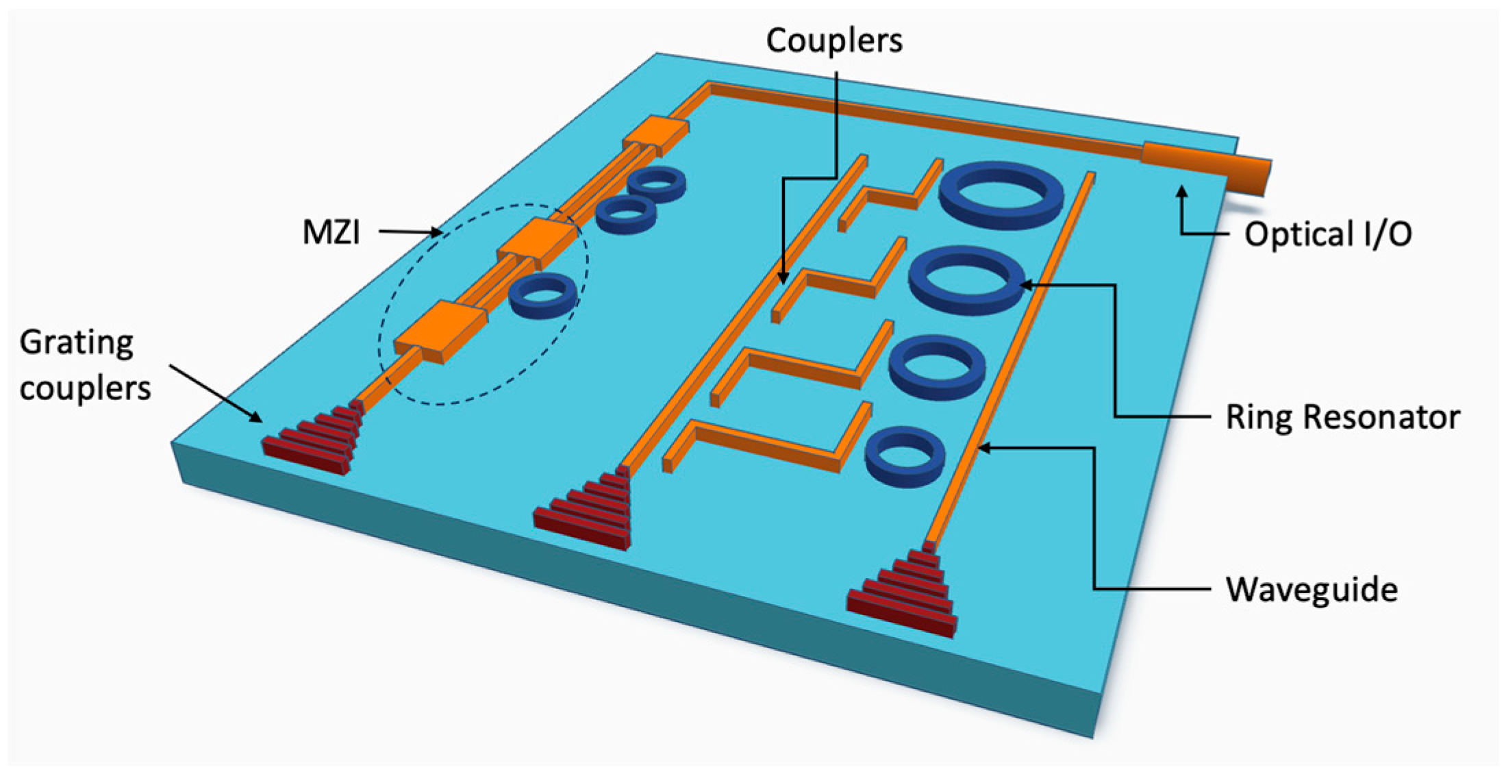
Figure 1. Examples of common silicon photonic passive devices.
Photonics 12 00928 g001
Figure 2. Schematic of (a) strip, (b) rib, and (c) SiN waveguides.
Photonics 12 00928 g002
Figure 3. (ac): Photos of Si3N4 chips featuring spiral waveguides up to 1.4 m long. An infrared camera is used to highlight light-scattering defects. (d): A schematic diagram showing the waveguide width d and spacing g. (e,f): Illustrating the measured optical losses at different waveguide lengths l and wavelengths. Reprinted with permission from [29].
Photonics 12 00928 g003
Figure 4. (a) SEM image of the optical facet and edge-coupler region on an SOI-PIC; (b) schematic of a multichannel fiber array; (c) schematic of the SOI edge-coupling structure based on the use of a Si inverse taper and a waveguide implemented in the BOX; (d) schematic of the SOI edge-coupling structure based on the use of a double-layer Si inverse taper and a waveguide; (e) schematic of the SOI trident EC structure. Reprinted with permission from [50].
Photonics 12 00928 g004
Figure 5. (a) Schematic of a 4 × 4 MMI. (b) Wavelength-dependent output transmission spectrum from various input ports.
Photonics 12 00928 g005
Figure 6. (a) Top view of a conventional DC. (b) Cross-sectional schematic of rib waveguides in the coupling region. (c) Normalized splitting ratio of DCs with different gaps. (d) Measured excess loss of DCs with different gaps. Reprinted with permission from [55].
Photonics 12 00928 g006
Figure 7. (a) Illustration of the resonator design. (b) Waveguide design. (c) Waveguide surface roughness scatters the guide mode energy into radiation mode and bulk absorption generates heat. (d) Point defects split resonances. (e) Defect bonds such as Si-O-H, Si-H, N-H, and dangling bonds lead to surface absorption. (f) The bus-ring coupler scatters energy into radiation modes and adds excess loss. Reprinted with permission from [65].
Photonics 12 00928 g007
Figure 8. A standard foundry MPW flow. Some common elements are shown, such as phase shifters, photodiodes, and gratings. Reprinted with permission from [76].
Photonics 12 00928 g008
Figure 9. Schematic of silicon photonic CPO technology. OE: optical engine. HBM: high bandwidth memory.
Photonics 12 00928 g009
Figure 10. The simulated results of arbitrary-input 1 × 2 power splitter. (a) The optimized structure. (b) The corresponding distribution of optical field. (c) The simulated spectra transmission of this device. (d,e) Two ways to arrange pixels as inverse design unit.
Photonics 12 00928 g010
Table 1. Waveguide performance on Si and SiN platform.
RefLoss (dB/cm)WavelengthPlatformBend Loss (dB)Core ThicknessWafer Size (inch)Polarization Handling
[24]0.06CbandSINNA730 nm4TE
[21]0.34ObandSIN0.018 for 50 μm NANATE
[11]0.274 ± 0.008CbandSOI<10−4 for 100 μm250 nm6TE
[28]0.055CbandSINNA870 nmNATE/TM
[23]0.014 @1.55 μmCbandSINNA720 nm4TE
[12]TE: 3.6 ± 0.1 @1.5 μm,
TE: 6.8 ± 0.2 @1.3 μm,
TM: 3.5 ± 0.1 @1.3 μm
1.2–1.7 μmSOI0.086 ± 0.005 for 1 μm,
0.013 ± 0.005 for 2 μm
220 nm8TE/TM
[19]0.157 @1.55 μm,
0.06 @1.58 μm
1.49–1.58 μmSIN0.013 for 50 μm,
0.0095 for 80 μm
400 nm8TE/TM
[13]2.01 ± 0.231CbandSOI0.05 ± 0.005 for 30 μm50 nm6TE
[22]0.000451.58–1.61 μmSINNA50 nmNATE
[16]0.16C + L bandSOINA500 nmNATE
Table 2. Optical I/O: the edge coupler and grating coupler performance.
RefTypeCoupling Eff. per Facet (dB)WavelengthPlatformMode
[46]Bident EC1.52 @1.55 μmCbandTFLNTE/TM
[42]2D GC2.541510–1560 nmSOITE
[45]Double-tip EC0.12/0.9 for TE/TM1070–1830 nmSINTE/TM
[47]3D multi-tip EC0.0682/0.0958 for TE/TM @1.55 μmCbandTFLNTE/TM
[38]GC0.97/1.05 for TE/TMCbandTFLNTE/TM
[48]3D EC0.29/0.24 for TE/TM1490–1670 nmTFLNTE/TM
[41]Vertical metal GC2.77/2.55 for TE/TMCbandSOITE/TM
[44]Double-tip EC1.52/2 for TE/TMObandSOITE/TM
[49]EC0.6/0.8 for TE/TMObandSINTE/TM
Table 3. Couplers: Y-brand, MMI, and DC performance.
RefTypeCoupling Efficiency per Facet (dB)WavelengthPlatformMode
[20]DC0.251510–1590 nmSINTE
[55]1 × 4 MMI0.13ObandSINTE
[58]DC0.24C + L + UbandSOITE
[57]2 × 2 MMI0.07 @1.31 μmObandSINTE
[54]DC0.272 @1.55 μmS + C + LbandSOITE
[36]DC0.42/0.28 for TE/TMC + LbandSOITE/TM
[53]Y-BRANCH0.1 @808 nm760–860 nmSINTE
[52]Y-BRANCH0.06 @1.55 μm1400–1565 nmSOITE/TM
[34]2 × 2 MMI0.08 @1.55 μmCbandSOITE
[35]DC0.1 @2 μm1.95–2.02 μmSOITE
Table 4. Filters: mircroring resonator performance.
RefQLoss (dB/cm)FWHMRadiusFSRWavelengthPlatformMode
[65]422 M0.0006906 kHz11.787 mm2.713 GHz1.55–1.65 μmSINTE
[62]2 M0.31.8 pm50 μm2 nmCbandSOITE
[64]45.7 M0.0180.1 pm (12.5 MHz)* 100 μm–4 mm0.52 nmCbandSINTE/TM
[15]2 M0.251.76 pm** 39 μm0.6 nm2–2.4 μmSOITE
[63]17 M0.0210.28 pm (35 MHz)100 μm25 GHz1.52–1.6 μmSINTE/TM
[66]1.01 M0.150.5–1.5 MHz250 μmNA3.5–4.6 μmSIGETE
[67]48 K8.50.07 nm (8.8 GHz)15 μm10.36 nm1.5–1.6 μmLNOITE
* Euler bends gradual width change. ** Effective Euler bends radius.
Table 5. Filters: array waveguide gratings (AWG) performance.
Ref# of
Channels
Loss (dB)Channel SpacingCrosstalkWavelengthPlatformMode
[72]8&168 CHs: 6.26,
16 CHs: 10.1
200 GHzNACbandSOITE
[56]40.66100 GHz9.6ObandSOITE
[74]80.51.85 nm30.21.88–2.02 μmSOITE
[73]80.50.5 nm23centered@ 760 μmSINTE
[75]6450.7 nm101.967–2.012 μmSOITE
Table 6. Summary of representative SiPh foundry platforms.
FoundryPlatform HighlightsKey MaterialsProcess Node(s)/Wafer Size
AIM PhotonicsUS-based open-access R&D hub; Comprehensive MPW platform (Active, Passive, Low-Loss, Sensor, QFlex); “Bite-size” process customization.Si, SiN (incl. thick film), Ge90 nm/45 nm base on 300 mm
IMECiSiPP platforms (iSiPP50G, iSiPP200); Advanced co-integration of SiN; Heterogeneous III-V/LNO integration via flip-chip/micro-transfer printing.Si, poly-Si, SiN, Ge, III-V (InP), LNO130 nm base on 200 mm, 300 mm
TSMCHigh-volume 65 nm SiPh process; COUPE™ advanced packaging for 3D stacking; Fully automated wafer-level testing (EWAT/OWAT).Si, SiN (low-temp PECVD)65 nm on 300 mm
GlobalFoundriesGF Fotonix™ platform; Monolithic RF-CMOS integration; Turnkey solutions including advanced packaging; 200 G/λ capable.Si, SiN, Ge90 nm, 45 nm on 200 mm/300 mm
Tower SemiconductorPH18 “open” foundry platform on 200 mm; Complements SiGe BiCMOS processes; Strong PDK support from major EDA vendors.Si, SiN, Ge180 nm base on 200 mm
This table provides a general overview of silicon photonics foundry capabilities and should be used for reference only. Please note that the specifications and offerings are subject to change. For the most up-to-date and representative information, it is essential to consult the official process design kits (PDKs) and documentation from each foundry, as their state-of-the-art technologies are constantly evolving.
Disclaimer/Publisher’s Note: The statements, opinions and data contained in all publications are solely those of the individual author(s) and contributor(s) and not of MDPI and/or the editor(s). MDPI and/or the editor(s) disclaim responsibility for any injury to people or property resulting from any ideas, methods, instructions or products referred to in the content.