1. Introduction
Silicon Bragg gratings have become an essential component of integrated photonic devices, finding applications in optical filters, sensors, WDM networks, optical signal processing, dispersion compensation, microwave photonics, and so on [
1,
2,
3,
4,
5,
6,
7,
8]. To date, most of the research has focused on traditional Bragg gratings fabricated on single-mode waveguides. As a two-port device, Bragg gratings typically require an additional 3 dB optical coupler or a circulator to obtain the reflected light. Nevertheless, using a 3 dB coupler can introduce an additional 6 dB loss at the drop port as the reflected signal must pass through the coupler twice, and a circulator is difficult to be integrated on SOI platform due to the lack of CMOS-compatible magneto-optic materials.
Multimode waveguide Bragg gratings (MWBGs) have recently attracted significant attention, as they can address the limitations of traditional Bragg gratings and offer additional advantages [
9,
10]. A MWBG with a specifically designed grating period can couple the forward TE0 mode to a backward higher-order mode at the target wavelength. The reflected higher-order mode is then converted to the fundamental mode and efficiently dropped via an adiabatic coupler. Therefore, the need for an extra 3 dB optical coupler or circulators is eliminated. A MWBG and a pair of adiabatic couplers form a four-port device, thereby functioning as an add-drop filter. However, previous studies on MWBGs have primarily focused on controlling specific spectral characteristics, such as increasing the sidelobe suppression ratio, sharpening the edges of the reflection response, and narrowing the operational bandwidth [
11,
12,
13]. In these efforts, the grating strength was modulated along the grating by adjusting the depths or positions of the sidewall grating corrugations. This technique is well known as apodization. However, exclusive modulation of the grating length is insufficient for realizing complex target spectra.
The synthesis of Bragg gratings has been first studied in the field of fiber optics. Several kinds of mathematical models and algorithms have been proposed for finding the grating structure (the grating strength and phase) from a specified, complex spectrum for fiber Bragg grating [
14,
15,
16]. Recently, complex spectral tailoring for sidelobe-suppressed filters, multi-channel filters and microwave photonics Hilbert transformers has been realized on the traditional Bragg gratings and Grating-assisted contra-directional couplers [
17,
18,
19]. However, the spectral tailoring of MWBGs has not been proposed and demonstrated on a silicon-on-insulator (SOI) platform.
In this work, we present a methodology aimed at engineering the complex spectral response of silicon MWBGs. We demonstrate the efficacy of the methodology through the experimental validation of multi-channel Gaussian spectral shaping. This study enables flexible manipulation of spectral characteristics in the integrated silicon MWBG-based devices, positioning them as promising candidates for reconfigurable photonic components including couplers, wavelength-selective switches, and add-drop multiplexers with customized spectral functionalities [
8,
20,
21,
22].
2. Design Methodology
This paper presents a fundamental design methodology for realizing an arbitrary complex spectral response using a silicon-based MWBG, in which implementing a multi-channel Gaussian-shaped filter serves as an example. The design process begins with the determination of a target complex spectral response. However, the initial target response is often not physically realizable and must be modified to become physically realizable before proceeding with the subsequent grating design. Once the physically realizable response is achieved, the discrete layer-peeling algorithm (DLPA) can be utilized to accurately calculate the grating strength and phase profiles required to meet the target response. In the next step, several fundamental parameters of the MWBG (including waveguide width, grating corrugation width, corrugation shape and grating period) are defined. Subsequently, the grating structure is established by modulating both the grating strength and phase along its length, in accordance with their respective calculated target profiles. Once the complete grating structure is created, its spectral response should be simulated to verify consistency with the realizable target response. Finally, the designed gratings are fabricated and experimentally characterized. The measured results are compared with the realizable target spectrum, enabling the iterative refinement of the design process.
2.1. Formation the Target Spectrum
Typically, the ideal objective is to achieve a specific reflection spectral response. For a multi-channel dispersionless Gaussian spectral MWBG, the target spectrum
r(
λ) can be expressed as
where
ri(
λ) represents the reflectance of the
i-th Gaussian peak at wavelength
λ,
Ai represents the peak reflectance,
λc is the central wavelength, and Δ
λ denotes the 3 dB bandwidth. It should be noted that a larger number of channels is enabled by setting
n as ≥3.
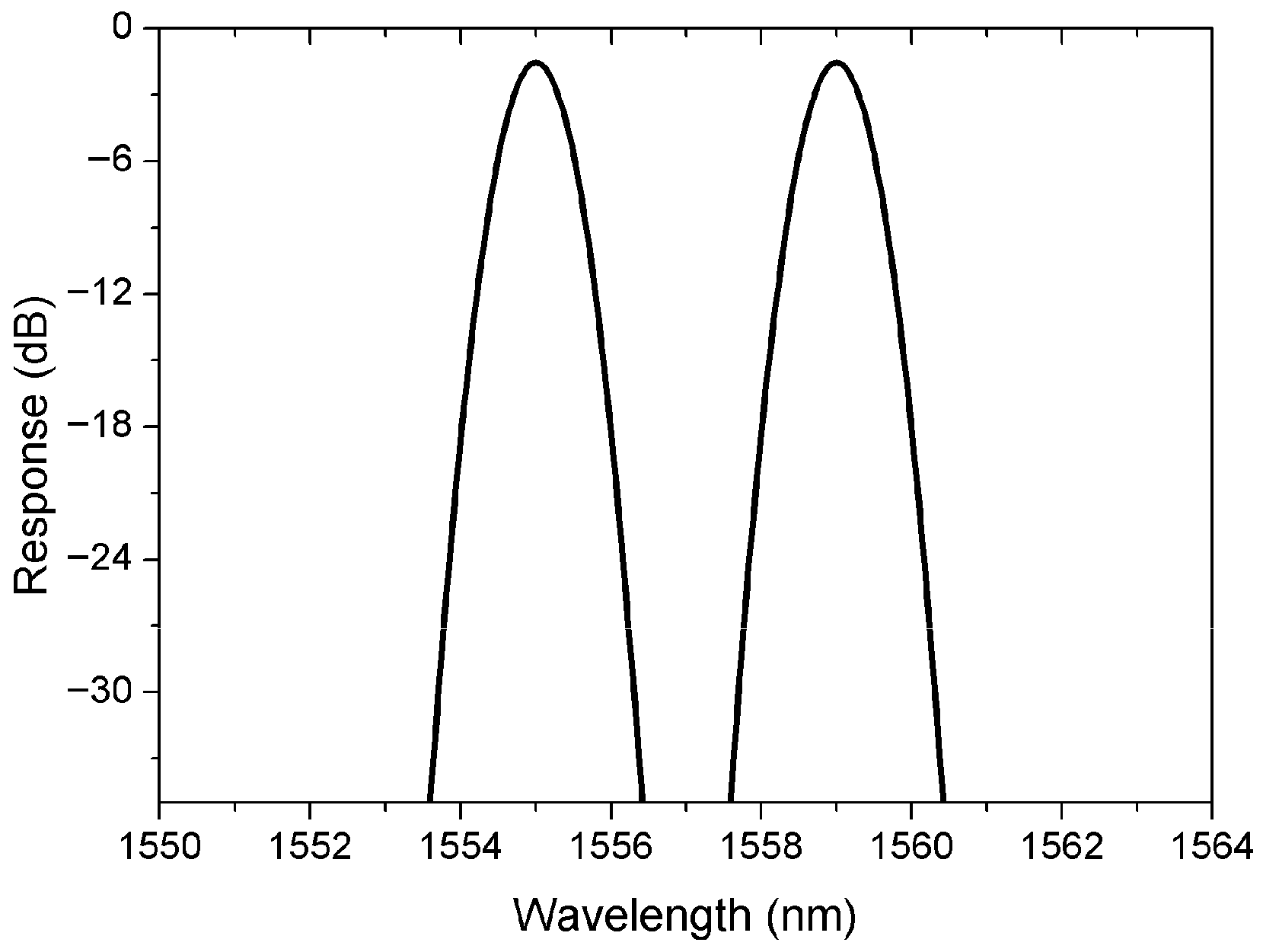
Figure 1 illustrates the target multi-channel MWBG spectrum with Gaussian profiles, showing a channel separation of 4 nm. The peak wavelengths are 1555 nm and 1559 nm, respectively. Each channel’s excess loss is 1.8 dB at the peak wavelength, and the 3 dB bandwidth of each channel is 1 nm.
As shown in
Figure 2a, the original impulse response of the target spectrum is infinite in length and non-causal (i.e., it extends into the negative spatial domain). To address this, the target spectral response must be converted into a physically realizable form. We modify it by first truncating the original impulse response and then shifting the truncated response into the positive spatial domain. The resulting modified impulse response, shown in
Figure 2b, is finite in length and causal.
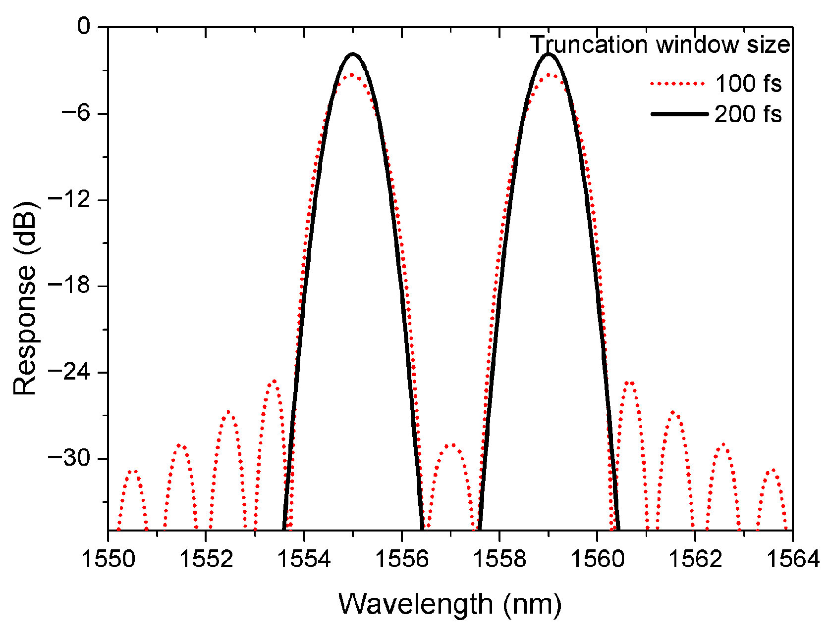
The physically realizable target response is obtained by applying the inverse Fourier transform to the modified impulse response. As shown in
Figure 3, the realizable spectral response with a truncation window size of 100 fs (range 50 fs to 150 fs in
Figure 2b) exhibits apparent degradation. Although the peak wavelengths match the designed spectral response, each channel suffers from 3.2 dB of excess loss, 1.2 nm of 3 dB bandwidth, and prominent sidelobes. This degradation is primarily caused by the insufficient truncation window size, which directly results in inadequate grating length. When the truncation window size increases to 200 fs (
Figure 2b), the realizable spectral response closely matches the designed spectrum.
2.2. Calculating the Complex Coupling Coefficient
The DLPA is a computationally efficient inverse scattering method that has been widely adopted for fiber Bragg grating synthesis. Its principle relies on solving the coupled-mode equations using piecewise scattering and a propagation matrix approach. When the piecewise section length is sufficiently small, the grating’s leading section can be determined solely by the impulse response’s leading edge. Thus, the grating structure can be reconstructed sequentially layer by layer, while the complex coupling coefficient (including the grating strength
κ(z) and phase
φ(z) distribution along the grating) is directly obtained via the DLPA method.
Figure 4 shows the grating strength and phase distribution synthesized derived from the realizable target spectral response. The
κ(z) profile exhibits significantly greater complexity than conventional MWBGs. Meanwhile, the required
φ(z) distribution manifests discrete π-phase shifts, corresponding to a dispersionless MWBG configuration [
18]. These structural characteristics necessitate a high-performance and reliable apodization technique for reliable grating realization.
2.3. Structure Design
The structure of the complex-synthesized MWBG proposed is schematically illustrated in
Figure 5. The 220 nm-thick silicon waveguide is embedded in a 2-μm buried oxide layer with a 2.2-μm silicon dioxide upper cladding. The multimode waveguide width W in the MWBG is configured at 850 nm to enable simultaneous propagation of both TE0 and TE1 modes. This grating structure employs rectangular sidewall modulations along the waveguide to achieve contra-directional coupling from the TE0 mode to the TE1 mode at selected wavelengths. For the target peak wavelength, the grating period Λ is determined as 314 nm via the phase matching condition.
The spectral response engineering hinges on the precise spatial modulation of both
κ and
φ of the grating, as defined by their respective distributions
κ(
z) and
φ(
z). A uniform MWBG can be treated as a superposition of two identical sub-gratings formed on either side of the multimode waveguide with a fixed phase offset of ∆
ϕ. To achieve precise
κ modulation, the lateral phase delay modulation (LPDM) method is implemented. This establishes the relationship between
κ and ∆
ϕ through the equation:
where
κmax is the maximum coupling efficient when ∆
ϕ is π. The phase shift distribution ∆
ϕ(
z) is then determined by the equation:
where
κn(
z) is the normalized
κ(
z).
The phase components of the spatial functions of the top and bottom sub-gratings are formed by the superposition of the phase delay term and
φ(
z):
Therefore, the spatial edge functions of the two sides of the MWBG can be expressed as follows:
where ∆
W is the grating corrugation width.
The spectral response of the designed MWBG was calculated using a three-dimensional (3D) finite-difference time-domain (FDTD) tool [
20]. The designed MWBG features a grating length of 587.76 μm (truncation window size: 200 fs) and a corrugation width of 10 nm, targeting a maximum coupling coefficient
κmax of 80 cm
−1. The calculated drop-port response, shown in
Figure 6, exhibits good agreement with the realizable target spectral response presented in
Figure 2.
3. Experiment Result
The filter was fabricated on a commercial SOI wafer via electron-beam lithography (EBL) and plasma etching. Optical characterization employed a fiber probe station with a tunable laser source for signal injection and optical power sensors for output detection.
Figure 7a schematically shows the characterization circuit for the designed MWBG-based filter. An adiabatic coupler was designed to convert the backward-propagating TE1 mode into the TE0 mode at the drop port.
Figure 7b shows a scanning electron microscope (SEM) image of the fabricated MWBG.
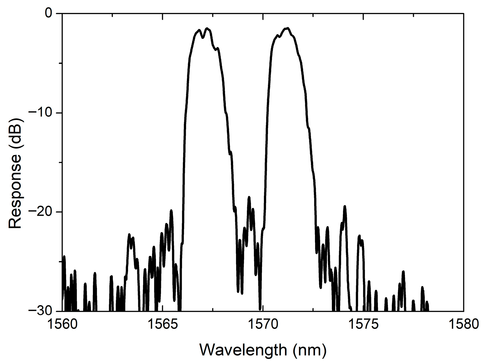
Figure 8 shows the measured normalized spectral response after calibrating out the insertion losses of the input and output grating couplers (GCs). The response exhibits a multi-channel Gaussian profile consistent with the target response with the designed 4 nm channel separation achieved. However, the measured peak wavelengths (1567 nm and 1571 nm) exhibit a redshift relative to design values, and the 3 dB bandwidth of each channel (1.3 nm) is slightly wider than intended. Based on the Bragg condition, the redshift primarily results from an increase in the effective refractive index. Our further analysis, supported by SEM measurements, indicates that the unintended enlargement of the waveguide width during fabrication is the dominant factor contributing to the redshift. The sidelobe suppression ratio of 18 dB and the excess loss of 1.4 dB are also measured.
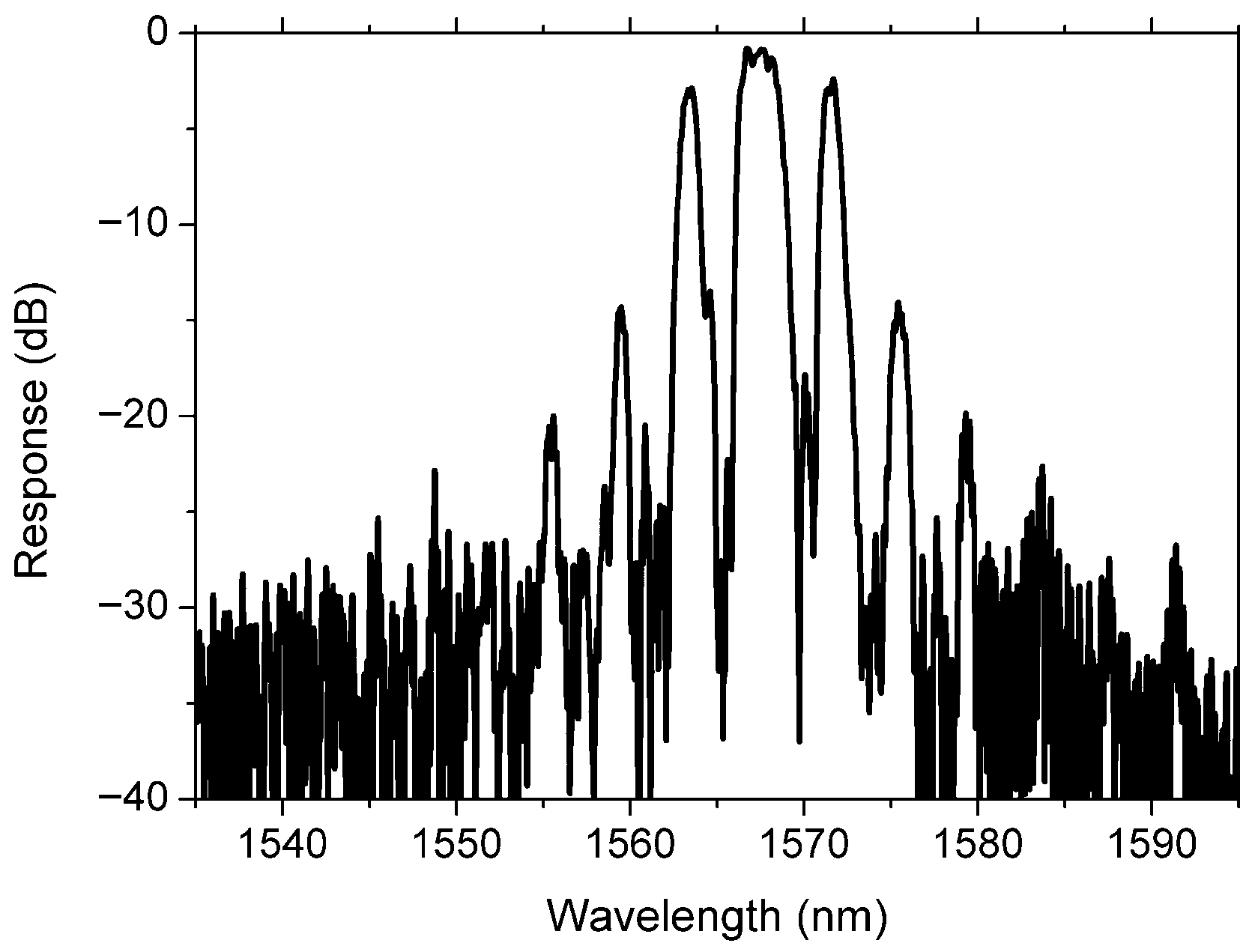
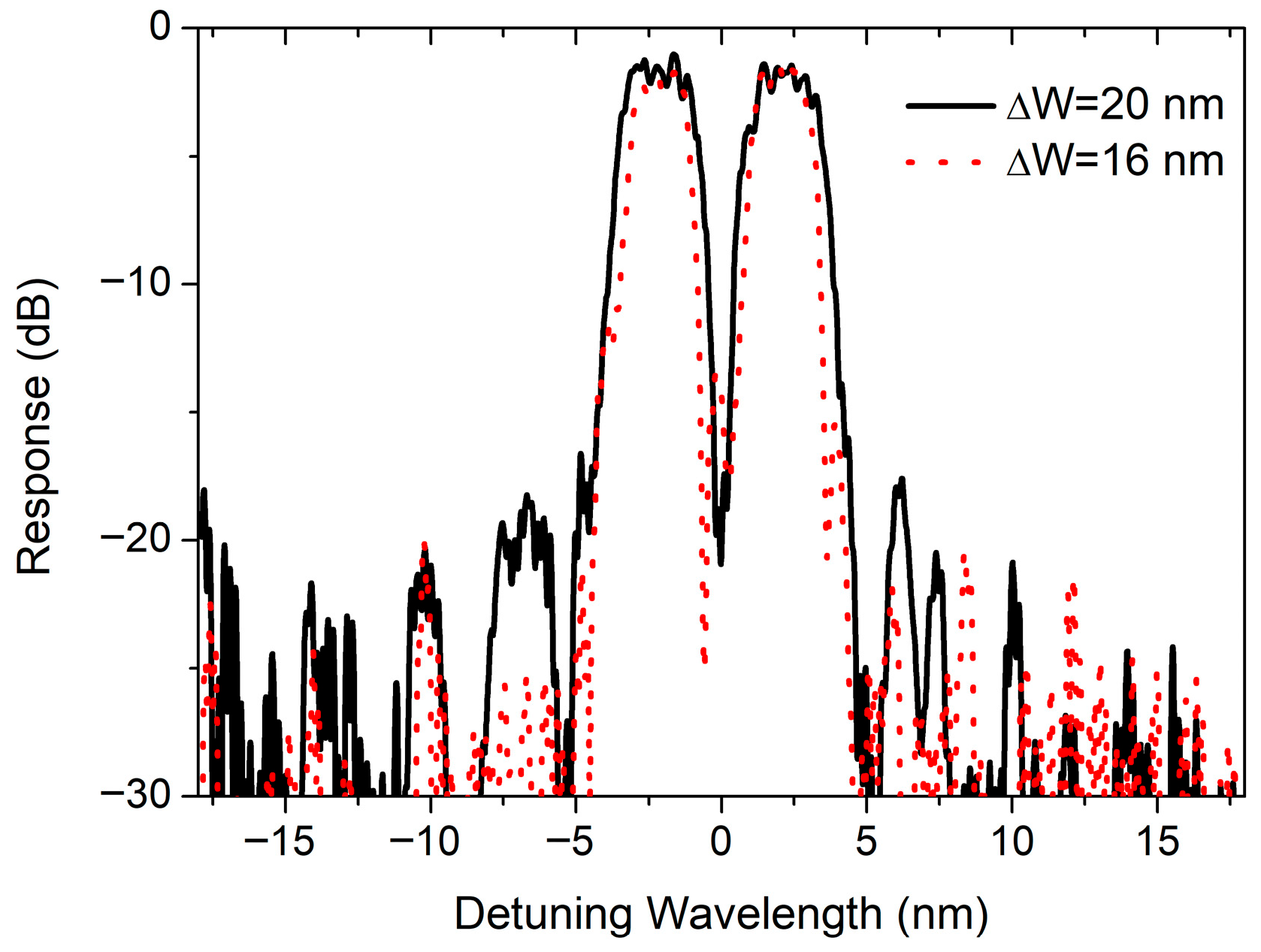
To investigate the influence of the grating strength κ(z) and phase φ(z), we also fabricated two MWBG variants: (1) grating maintaining κ(z) while with φ(z) = 0 and (2) grating with enhanced κ(z) while preserving φ(z).
Figure 9 presents the measured normalized spectral response of a MWBG with identical
κ(
z) to that in
Figure 4a but with
φ(
z) = 0. The resulting spectrum exhibits seven channels showing non-uniform bandwidths and insertion losses, demonstrating significant differences from the target spectral response. This confirms that the simultaneous engineering of both grating strength and phase distributions is essential to achieve specific reflection spectral responses.
To enhance
κ(
z), the corrugation width was increased to 16 nm and 20 nm in two respective MWBGs, while maintaining the
φ(
z) profile identical to that in
Figure 4b. As shown in
Figure 10, the measured normalized spectra for both devices exhibited the targeted multi-channel Gaussian profile. The measured 3 dB bandwidths are 2.6 nm and 2.0 nm, respectively, with channel separations of 4.1 nm. Although the stronger grating strength broadens the spectra compared with
Figure 8, it does not alter the spectral profile shape. Consequently, adjusting ∆
W provides a means to mitigate the influence of fabrication errors.
4. Conclusions
In summary, we have presented a methodology for tailoring the complex responses of MWBGs. The comprehensive design flow is introduced, demonstrating its effectiveness through the realization of a multi-channel Gaussian-shaped SOI-based MWBG filter by implementing LPDM apodization. This approach enables flexible control over the complex responses of MWBG-based devices, such as couplers, switches, and add-drop multiplexers, allowing for the implementation of customized spectral functionalities.
Author Contributions
Conceptualization, X.S.; methodology, X.L.; investigation, H.K.; data curation, W.W.; writing—original draft preparation, X.S.; writing—review and editing, H.Q. All authors have read and agreed to the published version of the manuscript.
Funding
This research was funded by the Natural Science Foundations of Fujian Province (2023J01350, 2023J01968, 2023J01974, 2025J011705, 2025J011707) and the Xinluo District Industry Academia-Research Technology Joint Innovation Project (2022XLXYZ004).
Data Availability Statement
The original contributions presented in this study are included in the article. Further inquiries can be directed to the corresponding author.
Conflicts of Interest
The authors declare no conflicts of interest.
References
- Murphy, T.E.; Hastings, J.T.; Smith, H.I. Fabrication and characterization of narrow-band Bragg-reflection filters in silicon-on-insulator ridge waveguides. J. Light. Technol. 2001, 19, 1938–1942. [Google Scholar] [CrossRef]
- Wang, X.; Flueckiger, J.; Schmidt, S.; Grist, S.; Fard, S.T.; Kirk, J.; Doerfler, M.; Cheung, K.C.; Ratner, D.M.; Chrostowski, L. A silicon photonic biosensor using phase-shifted Bragg gratings in slot waveguide. J. Biophotonics 2013, 6, 821–828. [Google Scholar] [CrossRef] [PubMed]
- Tan, D.T.H.; Ikeda, K.; Saperstein, R.E.; Slutsky, B.; Fainman, Y. Chip-scale dispersion engineering using chirped vertical gratings. Opt. Lett. 2008, 33, 3013–3015. [Google Scholar] [CrossRef] [PubMed]
- Shi, W.; Yun, H.; Lin, C.; Greenberg, M.; Wang, X.; Wang, Y.; Fard, S.; Flueckiger, J.; Jaeger, N.; Chrostowski, L. Ultra-compact, flat-top demultiplexer using anti-reflection contra-directional couplers for CWDM networks on silicon. Opt. Express 2013, 21, 6733–6738. [Google Scholar] [CrossRef]
- Simard, A.; Strain, M.; Meriggi, L.; Sorel, M.; LaRochelle, S. Bandpass integrated Bragg gratings in silicon-on-insulator with well-controlled amplitude and phase responses. Opt. Lett. 2015, 40, 736–739. [Google Scholar] [CrossRef]
- Yao, J. Microwave Photonics. IEEE J. Light. Technol. 2009, 27, 314–335. [Google Scholar] [CrossRef]
- Burla, M.; Cort’es, L.R.; Li, M.; Wang, X.; Chrostowski, L.; Azaña, J. Integrated waveguide Bragg gratings for microwave photonics signal processing. Opt. Express 2013, 21, 25120–25147. [Google Scholar] [CrossRef]
- Zhang, W.; Yao, J. A fully reconfigurable waveguide Bragg grating for programmable photonic signal processing. Nat. Commun. 2018, 9, 1396. [Google Scholar] [CrossRef] [PubMed]
- Qiu, H.; Yu, H.; Hu, T.; Jiang, G.; Shao, H.; Yu, P.; Yang, J.; Jiang, X. Silicon mode multi/demultiplexer based on multimode grating-assisted couplers. Opt. Express 2013, 21, 17904–17911. [Google Scholar] [CrossRef]
- Qiu, H.; Jiang, J.; Yu, P.; Dai, T.; Yang, J.; Yu, H.; Jiang, X. Silicon band-rejection and band-pass filter based on asymmetric Bragg sidewall gratings in a multimode waveguide. Opt. Lett. 2016, 41, 2450–2453. [Google Scholar] [CrossRef]
- Qiu, H.; Lin, L.; Yu, P.; Dai, T.; Jiang, X.; Yu, H. Narrow-Band Add-Drop Filter Based on Cladding-Modulated Apodized Multimode Bragg Grating. J. Light. Technol. 2019, 37, 5542–5547. [Google Scholar] [CrossRef]
- Liang, X.; Cheng, R.; Shen, X.; Yu, P.; Dai, T.; Qiu, H. Spectral-distortionless, flat-top, drop-filter based on complementarily-misaligned multimode-waveguide Bragg gratings. J. Light. Technol. 2021, 39, 5896–5901. [Google Scholar] [CrossRef]
- Ning, N.; Zhang, Q.; Wei, Z.; Wang, Q.; Xia, P.; Wang, Y. Ultra-Broadband Optical Filter Based on Step-Chirped Multimode Waveguide Bragg Grating. IEEE Photon. J. 2025, 17, 6601705. [Google Scholar] [CrossRef]
- Feced, R.; Zervas, M.N.; Miguel, M. An efficient inverse scattering algorithm for the design of nonuniformfibre Bragg gratings. IEEE J. Quantum Electron. 1999, 35, 1105–1115. [Google Scholar] [CrossRef]
- Skaar, J.; Wang, L.; Erdogan, T. On the synthesis of fiber gratings by layer-peeling. IEEE J. Quantum Electron. 2001, 37, 165–173. [Google Scholar] [CrossRef]
- Bland-Hawthorn, J.; Buryak, A.; Kolossovski, K. Optimization algorithm for ultrabroadband multichannel aperiodic fiber Bragg grating filters. J. Opt. Soc. Am. A 2008, 25, 153–158. [Google Scholar] [CrossRef]
- Cheng, R.; Chrostowski, L. Multichannel photonic Hilbert transformers based on complex modulated integrated Bragg gratings. Opt. Lett. 2018, 43, 1031–1034. [Google Scholar] [CrossRef]
- Cheng, R.; Zheng, Y.; Feng, J.; Wang, L. Spectral tailoring of silicon grating-assisted contra-directional couplers. Opt. Lett. 2024, 49, 7210–7213. [Google Scholar] [CrossRef]
- Xie, S.; Zhan, J.; Hu, Y.; Zhang, Y.; Veilleux, S.; Bland-Hawthorn, J.; Dagenais, M. Add–drop filter with complex waveguide Bragg grating and multimode interferometer operating on arbitrarily spaced channels. Opt. Lett. 2018, 24, 6045–6048. [Google Scholar] [CrossRef] [PubMed]
- Fernández-Hinestrosa, A.; Luque-González, J.M.; Cheben, P.; Schmid, J.H.; Wang, S.; Wangüemert-Pérez, J.G.; Molina-Fernández, I.; Ortega-Moñux, A. Nanophotonic Bragg grating assisted Mach–Zehnder interferometers for O-band add-drop filters. Sci. Rep. 2024, 14, 18492. [Google Scholar] [CrossRef] [PubMed]
- Praena, J.Á.; Carballar, A. Integrated Bragg Grating Spectra. Photonics 2025, 12, 351. [Google Scholar] [CrossRef]
- Liu, D.; Wu, H.; Dai, D. Silicon Multimode Waveguide Grating Filter at 2 μm. J. Light. Technol. 2019, 37, 2217–2222. [Google Scholar] [CrossRef]
| Disclaimer/Publisher’s Note: The statements, opinions and data contained in all publications are solely those of the individual author(s) and contributor(s) and not of MDPI and/or the editor(s). MDPI and/or the editor(s) disclaim responsibility for any injury to people or property resulting from any ideas, methods, instructions or products referred to in the content. |
© 2025 by the authors. Licensee MDPI, Basel, Switzerland. This article is an open access article distributed under the terms and conditions of the Creative Commons Attribution (CC BY) license (https://creativecommons.org/licenses/by/4.0/).
