1. Introduction
Terahertz (THz) wave is an electromagnetic wave with a frequency range of 0.1–10 THz [
1], which has many unique advantages such as strong penetration, fingerprint spectrum, and low photon energy [
2]. It has great potential in imaging, nondestructive testing, spectral analysis, and so on [
3,
4,
5]. Even though applications of THz wave have been widely developed, the lack of stable THz sources affects its performance and application fields [
6]. Optically pumped gas THz laser (OPGTL) is a practical THz radiation source that has been studied widely due to its advantages of high output power, low cost, high beam quality, and stable operation at room temperature [
7,
8]. The output power and spectral properties of the OPGTL are influenced by numerous factors, particularly the optical properties of the resonator’s input and output coupler [
9]. Attaining an input coupler with high transmittance for pump light and high reflectance for THz light is the key to achieving high efficiency and high-power output of an OPGTL. Furthermore, the maximum laser output power is enabled by an optimal transmittance for the output coupler when other pertinent factors remain constant [
10,
11].
Utilizing a pinhole-coupled mirror as the resonator’s mirror offers an effective solution for the resonator cavity in continuous wave OPGTLs. This approach involves the pinhole-coupled mirror acting as the input coupling mirror for the THz resonator, channeling the pump light beam efficiently. By employing a lens to focus and compress the pumping light beam, it ensures that a significant portion of the pumping light is transmitted into the terahertz resonator. This method not only facilitates the coupling of nearly all the pump light but also guarantees a high level of reflectivity for the terahertz light, enhancing the system’s efficiency. In addition, for the output coupling pinhole mirror, different output coupling rates of the terahertz resonator can be achieved by replacing apertures of different sizes, thereby optimizing the laser resonant cavity and obtaining the optimal output power. However, the non-uniformity of the focusing pump beam and the hard-edge diffraction of the output coupling aperture will reduce the conversion efficiency of the laser and the quality of the laser beam [
12]. In contrast, Fabry–Perot (FP) THz resonators can achieve high pump laser conversion efficiency and low divergence laser beam output due to the advantage of uniform coaxial pumping [
10]. Despite these benefits, current coating technologies face significant challenges in producing input coupler mirrors that simultaneously achieve high transmission for 9–11 µm pump light and high reflection for THz light.
In recent years, metasurfaces have obtained a number of exciting applications at THz frequencies, such as imaging [
13], holography [
14], and broadband microstrip antenna [
15]. Metasurfaces are artificial subwavelength structures with unnatural properties that enable the electromagnetic field to be manipulated by well-arranged nanostructures/microstructures [
16]. In order to obtain the optical properties of the metasurfaces, rigorous and unapproximated electromagnetic calculations of the interaction between metasurfaces and light may need to be considered [
17]. The finite-difference time-domain (FDTD) method is a general electromagnetic field simulation technique that is widely used in the field of metasurfaces [
18,
19].
The metal subwavelength structure is a kind of metasurfaces structure that has been discovered to have transmission enhancement phenomenon, thus promoting the rapid development of THz devices, and various subwavelength periodic metal mesh structures are widely used in different THz devices [
20,
21]. For example, the capacitive metal meshes were plated on ZnSe mirror and Si mirror as input and output couplers of Fabry–Perot cavity THz pulsed laser, and their actual transmittance for THz laser was measured by Qi et al. [
22]. A wedged capacitive strip-grating output coupler deposited on silicon wafer was also proposed by them, and its transmittance performance has been studied theoretically [
10]. An equivalent circuit model to analyze the characteristics of two-dimensional metal grid structures with or without a dielectric substrate was proposed by Whitburn and Compton [
23]. Unfortunately, predictions based on this model indicate that a two-dimensional metal grid with a substrate cannot achieve high transmission for pump light and high reflection for terahertz waves simultaneously due to the difference in refractive indices on its two sides. To achieve high transmission for pump light and high reflection for terahertz waves, a metal grid without a substrate may be a good choice. Therefore, it is necessary to conduct detailed research on the design, optimization, and simulation verification of two-dimensional metal grids without substrates.
In this paper, a simulation study was carried out to investigate the influence of the structural parameters of the substrate-free metal mesh on the transmission and reflection performance of longwave mid-infrared and THz light. Then, based on the simulation result of substrate-free metal mesh, a high-efficient FP resonant cavity for CH3OH gas THz laser has been designed. The transmitted and reflected light fields of the FP resonant cavity metal mesh mirrors were simulated by using the FDTD method for the vertical incidence of pump light and THz light waves, respectively. For the pump-coupled cavity metal mesh, the FDTD simulation results show that it has high transmittance for pump light and high reflectivity for THz light, which are in good agreement with the design specifications. In addition, the FDTD optical field simulation results also show that the propagation direction of the pump light after passing through the metal mesh remains consistent with the incident light. The validation results of the optical field characteristics of the substrate-free metal mesh show that it can be used as an ideal input coupling cavity mirror of an FP resonant cavity for optically pumped gas THz lasers. Finally, the effects of mesh period and linewidth errors on the pump light and THz light during the fabrication of the metal mesh are also quantitatively simulated.
2. Theoretical Model
An equivalent circuit model for analyzing the properties of one-dimensional strip metal gratings was first proposed by Marcuvitz [
24]. In 1970, the model was extended to include two-dimensional metal mesh structures by Ulrich et al. [
25]. Subsequently, in 1985, calculations for the transmittance, reflectance, and absorptance of inductive and capacitive metal meshes with dielectric substrates were formulated by Whitbourn and Compton [
23]. The equivalent circuit model represents the metal mesh and its surrounding electromagnetic environment through the utilization of equivalent inductance, capacitance and resistance elements, and facilitating analyzes of the properties of the overall electromagnetic network. Based on the equivalent circuit elements, metal meshes are categorized into inductive and capacitive types, and their physical structures are complementary [
26]. The symmetry of the two-dimensional inductive metal mesh determines that the polarization direction of the incident light does not affect its transmittance [
23,
24,
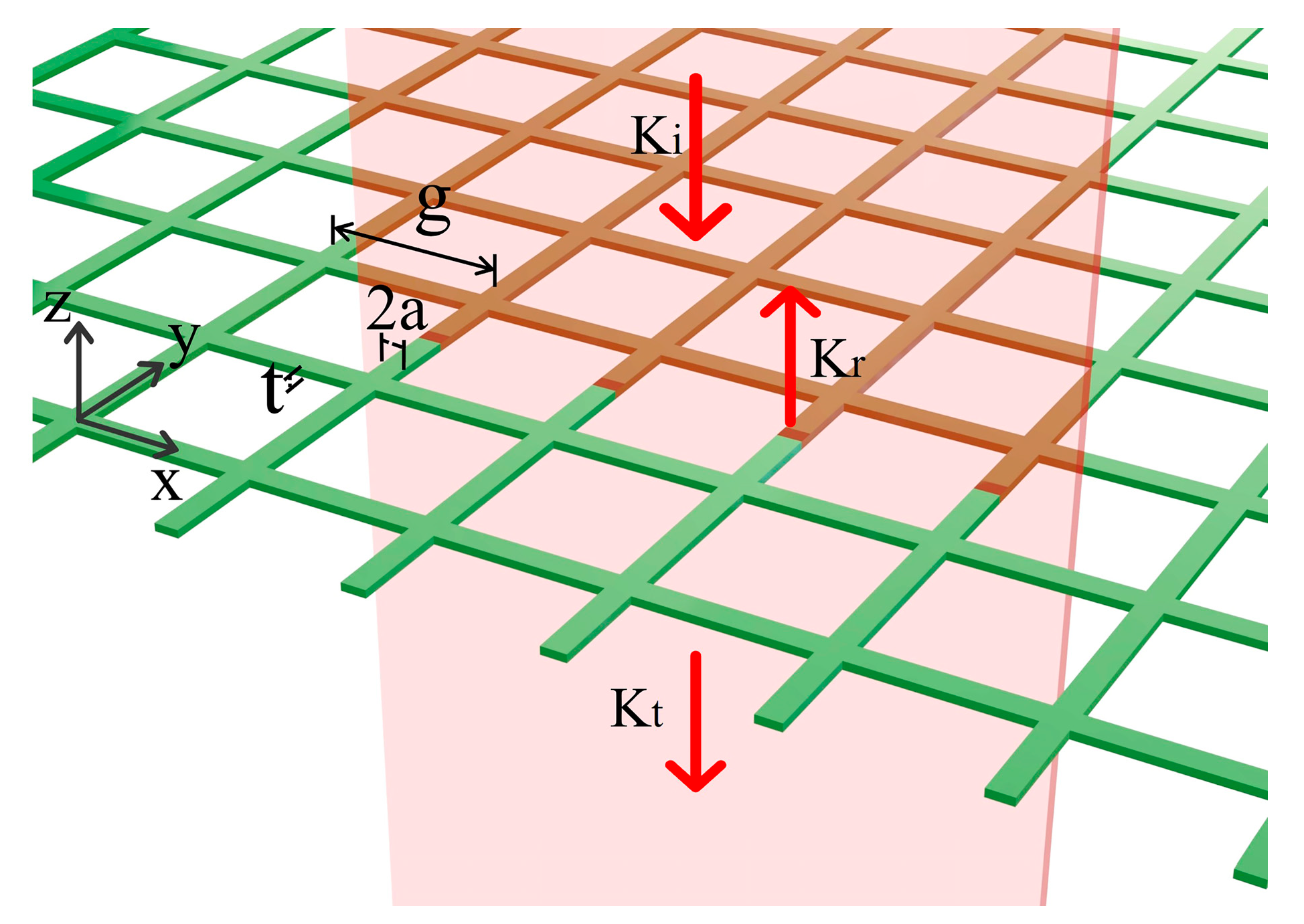
25]. Therefore, it is generally selected to make two-dimensional inductive metal mesh, as shown in
Figure 1, where g is the mesh period, 2a is the linewidth, and t is the thickness of metal mesh.
Considering the dielectric refractive index between the two sides of metal mesh is n
1 and n
2, respectively, and n
2 ≥ n
1. According to the microwave transmission line theory, to ensure that transmission light has only zero-order diffraction, the metal mesh period g must satisfy the following conditions: g < λ/n
1 and g < λ/n
2, where λ represents the wavelength of incident light. Neglecting the thickness of the metal mesh, the transmittance of metal mesh to incident light is given by the following [
23]:
where
ZS is the impedance of incident light in free space and
X represents the equivalent reactance of metal mesh. For two-dimensional inductive metal meshes,
where
ω is the normalized frequency and is defined as
ω = g/λ, and
ω0 signifies the resonant frequency, which is approximately unity.
In the presence of the thickness of metal mesh, Whitebourn et al. summarized the equivalent linewidth of the metal mesh in a vacuum environment [
23]. Under the conditions of t << 2a, a << g, g < λ, the relationship between the equivalent linewidth parameter and the actual linewidth parameter of inductive metal mesh is given by the following:
where a
eff denotes the linewidth parameter of the metal mesh without thickness, a represents the linewidth parameter of the metal mesh with certain thickness, and t is the thickness parameter of the metal mesh with certain thickness. In order to avoid the loss from side-wave diffraction, the mesh period parameter should be less than the wavelength of incident light (g < λ) when designing the metal mesh without substrate. Due to the small absorptance of metal mesh, Ulrich’s model does not consider this [
26].
3. Results and Discussion
The distinctive optical characteristics of metal meshes are attributed to the periodic arrangement of subwavelength structures [
16]. Consequently, alterations in the mesh period, linewidth, and thickness of the metal mesh structure will affect its optical characteristics. To attain metal meshes exhibiting high transmittance for pump light and high reflectance for THz light, or specific transmittance for THz light, it is necessary to analyze the influence of the mesh period, linewidth, and thickness of metal mesh on the metal mesh transmittance.
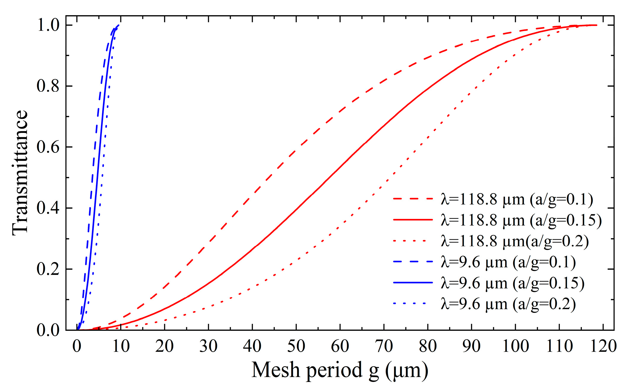
Taking light at 9.6 μm and 118.8 μm wavelengths as an example, the simulation curve of
Figure 2 is obtained from Equation (1).
Figure 2 gives the influence of the mesh period g on the metal mesh transmittance for various a/g parameters in the case of neglecting the thickness of the metal mesh.
Figure 2 reveals that the transmittance of the metal mesh increases with the increase in the mesh period, and the transmittance relatively slow increases when the mesh period is relatively small. Then, as the mesh period continues to increase, the transmittance increases relatively fast until it gradually approaches unity. It is crucial to note that the maximum mesh period should not surpass the wavelength of the incident light. Additionally,
Figure 2 also demonstrates that the transmittance of the metal mesh decreases with the increase in the linewidth under a constant mesh period. Therefore, it is necessary to determine an appropriate value for the a/g parameter in the simulation. For uniformity of the simulation results, the a/g value is consistently set to 0.15 in the following unless otherwise specified.
The mesh period g and equivalent linewidth a
eff of the metal mesh with specific transmittance for specific wavelength can be obtained when the thickness of the metal mesh is negligible. However, the actual metal mesh possesses a non-negligible thickness, and the relationship curve among the actual metal mesh thickness t, linewidth 2a, and its equivalent linewidth a
eff obtained from Equation (4) are shown in
Figure 3. Specifically,
Figure 3 shows the curve corresponding to each value of the equivalent linewidth a
eff, and the coordinates of each point on these curves all signify the linewidth and thickness of the metal mesh with a certain thickness. Therefore, an arbitrary point on the corresponding curve can be selected to ascertain the actual parameters of the metal mesh when an a
eff value is determined. Due to practical process constraints, the choice of thickness and linewidth parameters should be as eclectic as possible.
To verify the feasibility of the metal mesh, metal meshes were designed utilizing the mesh parameters derived from
Figure 2 and
Figure 3, which are periodic structures, and FDTD simulation is used to verify and analyze the optical properties of the partial mesh of metal mesh [
19]. In FDTD simulations, a plane wave source is employed, periodic boundary conditions are applied, and frequency domain field/power monitors are utilized, with the Yee mesh discretization scheme adopted for spatial discretization. In the simulation, the intensity of default plane wave source is normalized to 1 and the phase is 0. In addition, all metal meshes were designed as 6 × 6 partially periodic structures and are uniform meshes. During the simulation, a plane wave is incident perpendicularly on the metallic mesh. The reflected and transmitted light field intensities are recorded, the transmittance and reflectance are subsequently calculated, and the simulation results include absorption losses, electrical losses, and diffraction losses.
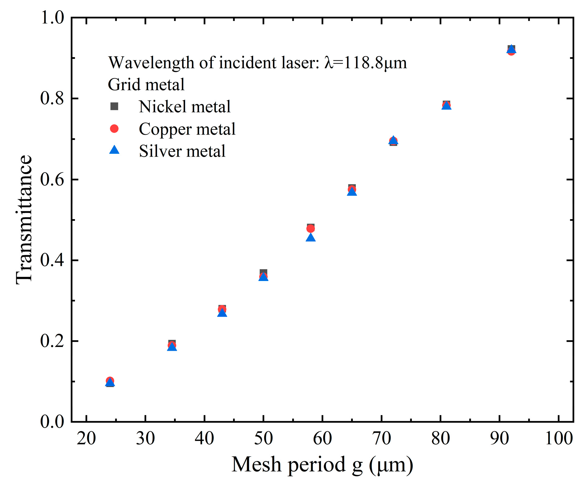
In FDTD simulations, material models are classified into CRC, Johnson, and Palik. Among them, Palik refers to the manual of the American Handbook of Solid Optical Constants. The parameters of metal mesh with different transmittance for 118.8 μm THz light were selected, and their 3D models were constructed in FDTD simulations. After that, the influence of different materials on the transmittance of metal mesh was studied by the Palik model, as depicted in
Figure 4. It can be seen from
Figure 4 that the material has minimal influence on the transmittance of metal mesh. For example, a metal mesh with theoretical transmittance of 70% for 118.8 μm THz light was obtained, and its transmittance was 69.24% calculated via the FDTD method when nickel was utilized as the metal mesh material. However, when copper and silver are used, the transmittance of this metal mesh for 118.8 μm THz light is 69.54% and 69.5%, respectively. Considering the susceptibility of silver and copper to oxidation, nickel may be the preferred material for the actual metal mesh. Unless otherwise specified, nickel will be consistently utilized as the metal mesh material in subsequent discussions.
According to
Figure 2 and
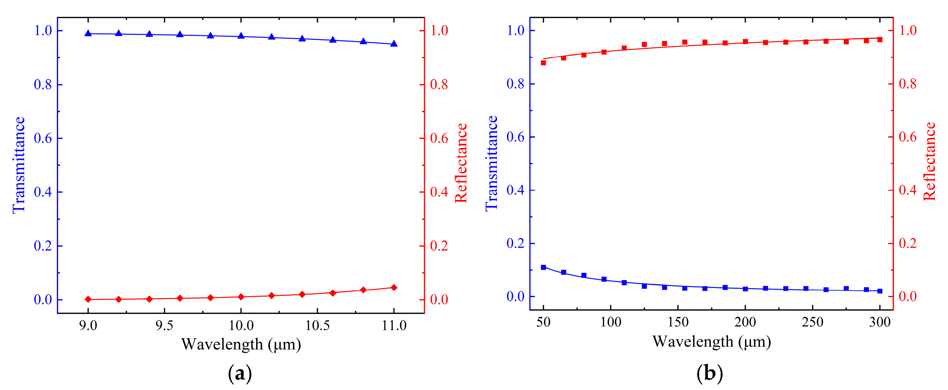
Figure 3, a metal mesh with g = 9 μm, 2a = 1.5 μm, and t = 1 μm was obtained, and its theoretical transmittance for 9.6 μm pump light is 99%. To ascertain the feasibility of this metal mesh as an input coupler for OPGTL, the transmittance and reflectance of the metal mesh are simulated via the FDTD method, and the results are shown in
Figure 5. The results indicate that the metal mesh exhibits a transmittance above 95% and a reflectance below 5% for 9–11 μm pump light. For 50–300 μm THz light, the reflectance of the metal mesh is found to be above 87%, with a transmittance below 12%. In addition, the transmittance of the metal mesh diminishes with the increase in wavelength, and the reflectance is opposite. For 9–11 μm pump light, the minimum transmittance of the metal mesh is recorded as 95.03%, and the corresponding maximum reflectance is 4.59%, as shown
Figure 5a.
Figure 5b illustrates that the metal mesh has a minimum reflectance of 87.86% and a maximum transmittance of 11.01% for THz light in the range of 50–300 μm. This shows that the designed metal mesh as an input coupler can be applied to high-efficient FP resonant cavity for CH
3OH gas THz laser. As can be seen from
Figure 5, the transmittance of the metal mesh to 9.6 μm pump light is found to be 98.36%, while its reflectance to 118.8 μm THz light is 93.37%.
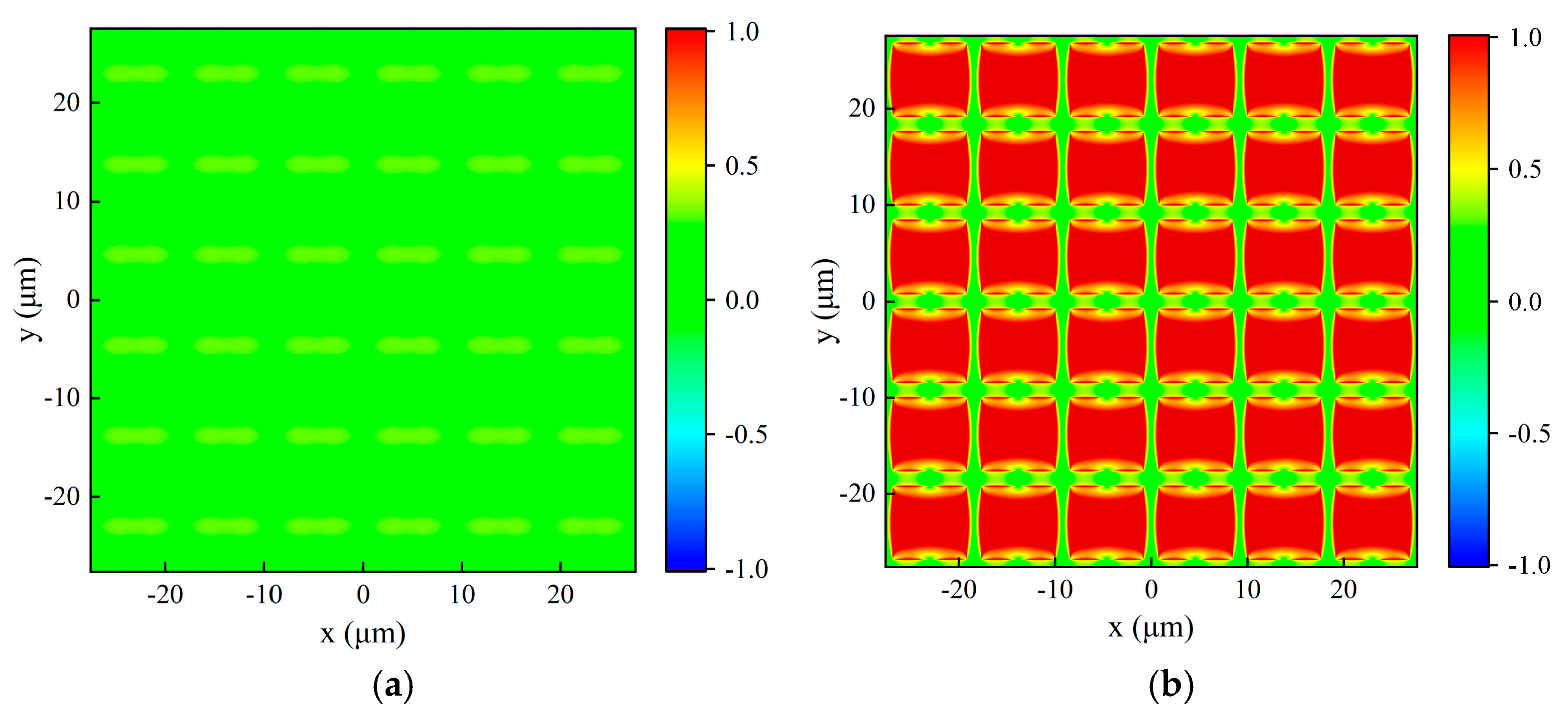
For the metal mesh with g = 9 μm, 2a = 1.5 μm, and t = 1 μm, the reflected and transmitted light fields in x-y plane under vertical incidence of the x-polarized plane wave of 9.6 μm were simulated by FDTD, as illustrated in
Figure 6. In
Figure 6 and similar figures below, the negative sign on the color scale represents the direction of the light field. The origin of the three-dimensional coordinate system is located at the center of the metal mesh, and the metal mesh is parallel to the x-y plane. The light source is situated at a half-wavelength distance above the metal mesh, and the plane wave is vertically incident along the opposite direction of z. The reflected light field is extracted at z = 5.3 μm and the transmitted light field is extracted at z = −0.5 μm.
Figure 6 presents that due to the periodic structure of the metal mesh, the variation in the light field is also periodic. The average light field intensity of
Figure 6a,b are 0.0135 and 0.9836 by calculation, respectively, which is basically consistent with the simulation of the transmittance of metal mesh to 9.6 μm light.
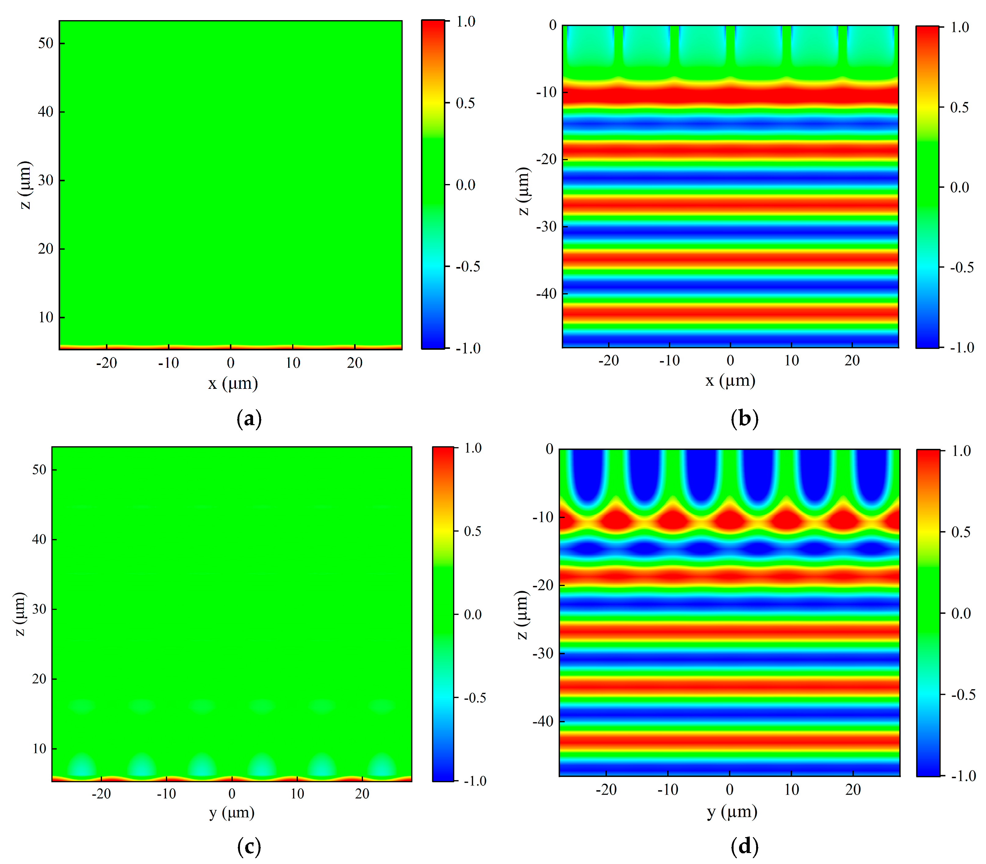
The reflected and transmitted light fields of the above metal mesh in x-z plane and y-z plane under the vertical incidence of the x-polarized plane wave of 9.6 μm are presented in
Figure 7 by the FDTD method. The spatial position of the metal mesh and the light source is the same as described in the previous paragraph. The reflected light field is also extracted from above the light source, while the transmitted light field is obtained from the x-z and y-z planes positioned below the metal mesh. It can be clearly seen from
Figure 7 that the reflected wavefront is now propagating along the z direction and the transmitted wavefront propagates in the opposite direction to z. This phenomenon indicates that the propagation direction of the vertically incident plane wave remains unchanged after passing through the metal mesh, continuing to propagate along the direction of incident light propagation, and the reflected light propagates in the opposite direction of incident light propagation.
Figure 7 displays that the light field of the plane wave undergoes variations near the position of the metal mesh, probably attributed to the diffraction of light. As can be seen from
Figure 5 and
Figure 6, the metal mesh has a transmittance of 98.36% and a reflectance of 1.35% for 9.6 um light, so that the absorption losses, electrical losses, and diffraction losses of plane wave passing through metal mesh are approximately 0.29%.
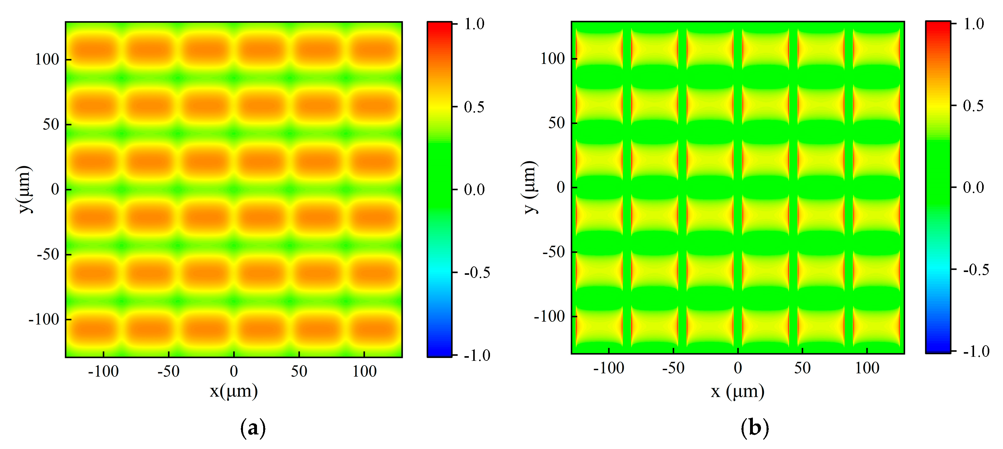
The output coupler of OPGTL has a specific coupling ratio for specific THz light. Therefore, a metal mesh with g = 43 μm, 2a = 6.8 μm, and t = 5 μm was designed and its theoretical transmittance for 118.8 μm THz light is 30%. A similar optical field characteristics analysis was performed on this metal mesh.
Figure 8 shows the reflected and transmitted light fields in the x-y plane under vertical incidence with the x-polarized plane wave of 118.8 μm. The reflected light field is extracted at z = 59.4 μm, and the transmitted light field is extracted at z = −0.5 μm. The average intensities of reflected and transmitted light fields are 0.6869 and 0.2815, respectively. Therefore, the reflectance and transmittance of this metal mesh to 118.8 μm THz light are 68.69% and 28.15%, respectively. The absorption losses, electrical losses, and diffraction losses of the plane wave passing through metal mesh are approximately 3.16%.
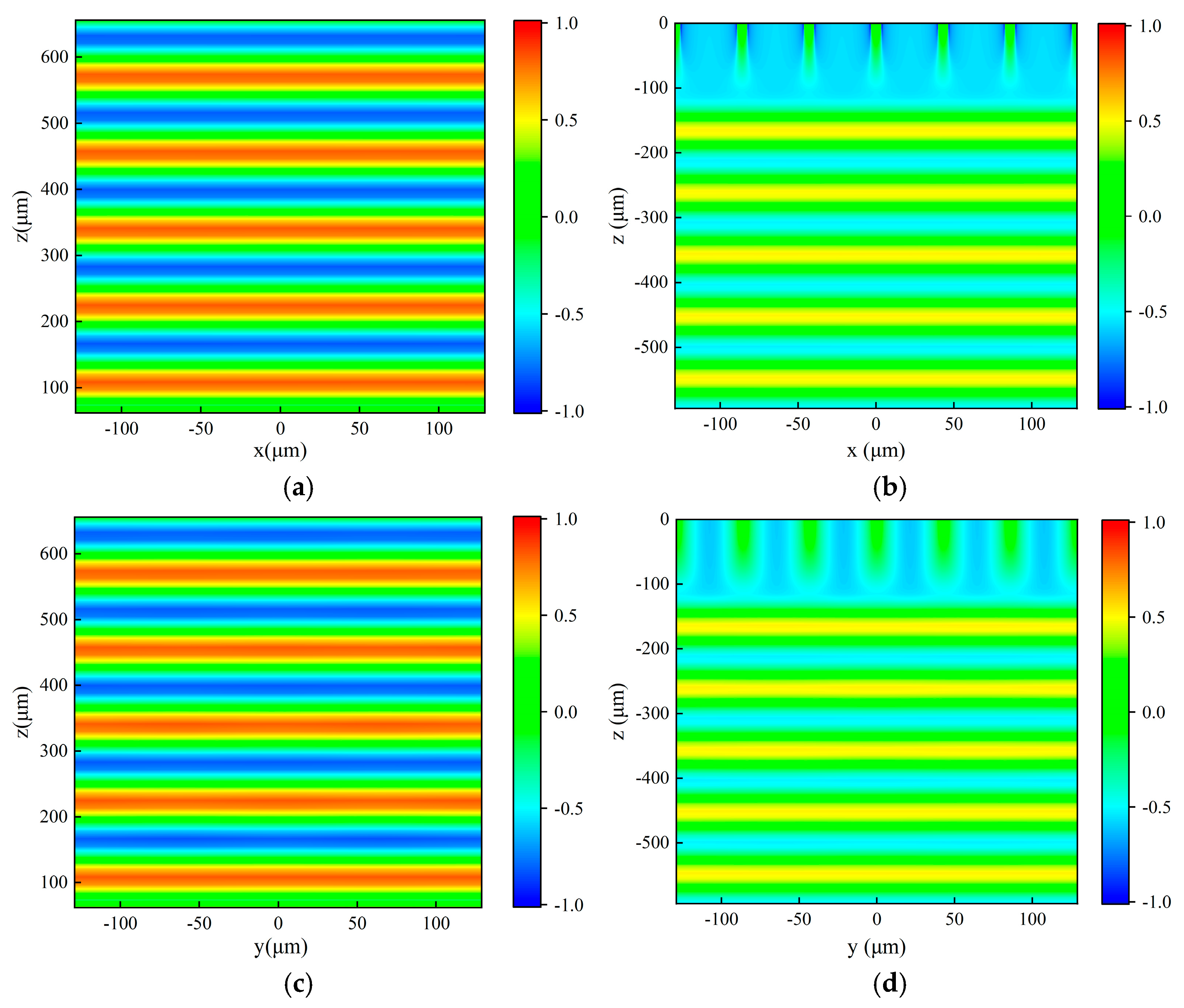
Figure 9 represents the reflected and transmitted light fields in x-z plane and y-z plane under the vertical incidence of the x-polarized plane wave of 118.8 μm. The result shows that the propagation direction of the vertically incident 118.8 μm light has no change in propagation direction after passing through the metal mesh.
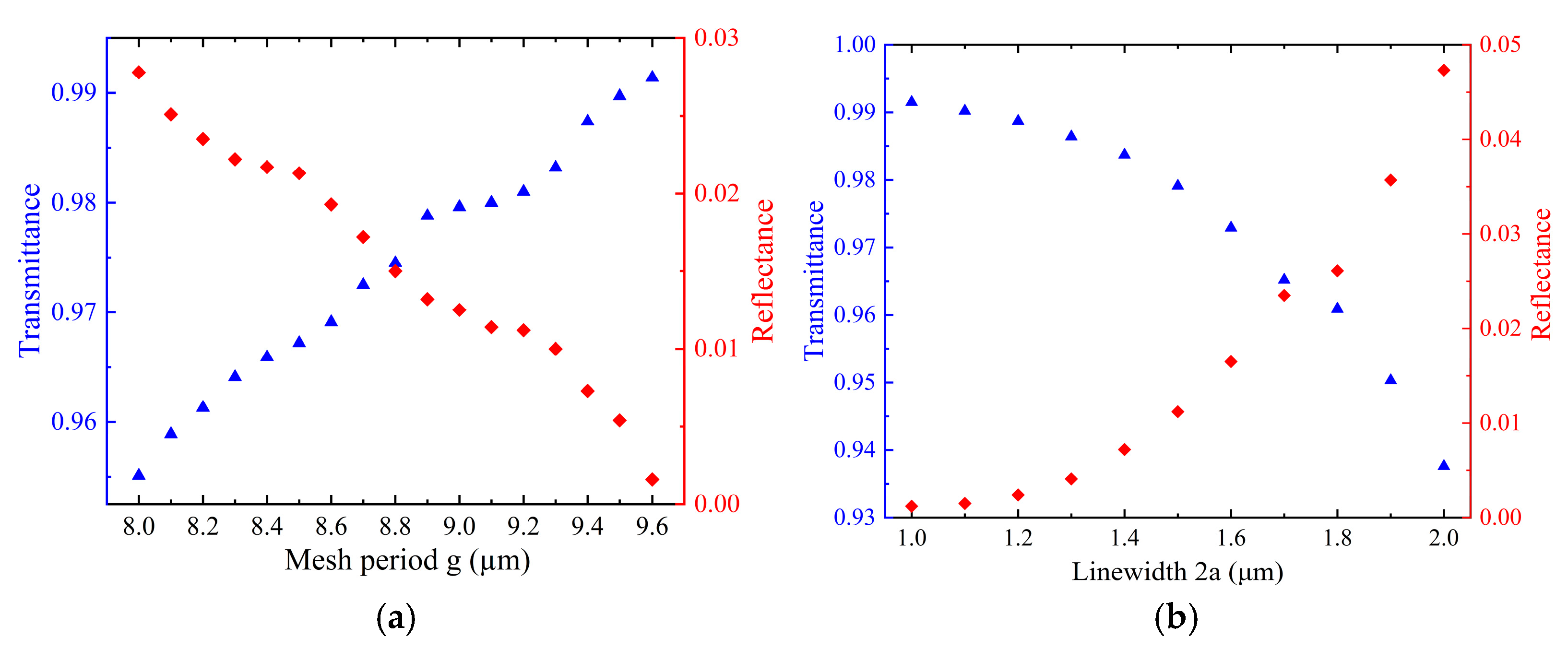
It is noted that errors will be encountered in the actual processing of the mesh period and linewidth of the metal mesh. The influence of the error of mesh period g and linewidth 2a on the transmittance and reflectance of the metal mesh is analyzed by FDTD simulation for a metal mesh with g = 9 μm, 2a = 1.5 μm, and t = 1 μm, as shown in
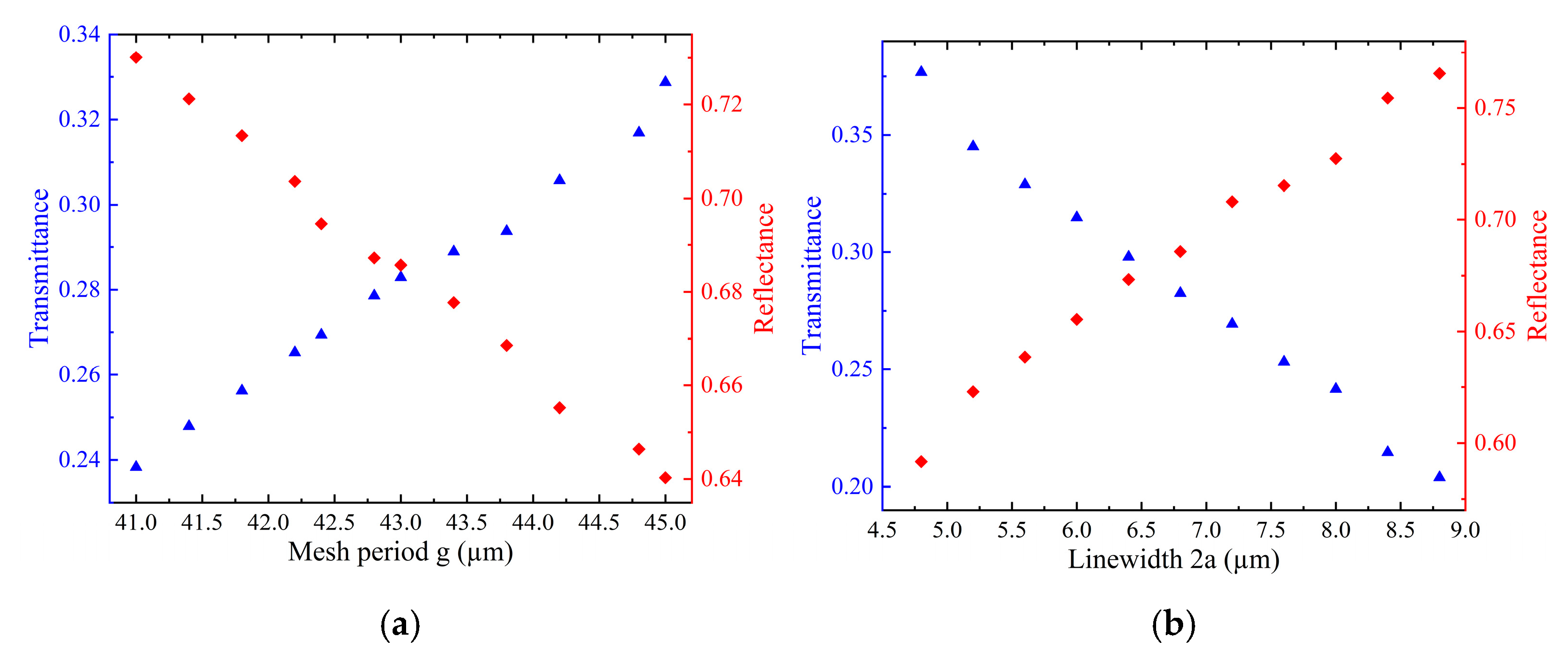
Figure 10. In the FDTD calculation, the transmittance of the metal mesh to 9.6 μm pump light is maintained above 95% when the linewidth 2a remains constant and the mesh period g varies within the range of 8–9.6 μm. Similarly, when the mesh period g is held constant and the linewidth 2a varies within the range of 1–2 μm, the transmittance of the metal mesh to 9.6 μm pump light is above 93%. A similar method was applied to the metal mesh with g = 43 μm, 2a = 6.8 μm, and t = 5 μm, where the incident wavelength is 118.8 μm, and the results are shown in
Figure 11.
4. Conclusions
In summary, a substrate-free metal mesh structure was designed for OPGTL resonators, and the transmittance of metal mesh at different wavelengths can be changed by changing the mesh period, linewidth, and thickness parameters of metal mesh. The influence of the metal mesh period and linewidth on transmittance is analyzed quantitatively. The results indicate that the transmittance of metal mesh increases with the increase in the mesh period, and it tends to be saturated when the mesh period is close to the incident light wavelength. Meanwhile, the transmittance of metal mesh decreases with the increase in the linewidth. Furthermore, the equivalent linewidth aeff is employed to ascertain the actual linewidth and actual thickness of the metal mesh; the selection of parameters should be compromised as much as possible.
Taking the THz laser with the 118.8 µm of CH3OH optically pumped by the 9.6 µm CO2 laser line for instance, two kinds of metal mesh were devised as input and output couplers of the resonator, and the transmittance and reflectance of the metal meshes are verified by the FDTD method. A metal mesh with g = 9 μm, 2a = 1.5 μm, and t = 1 μm is used as the input coupler. The metal mesh theoretically has high transmittance for 9.6 μm light and high reflectance for 118.8 μm light, and the FDTD calculation results show that the metal mesh exhibits a transmittance of over 98.36% for pump light with a wavelength range of 9.6 μm and a reflectance of over 93.37% for THz light with a wavelength range of 118.8 μm. A metal mesh with g = 43 μm, 2a = 6.8 μm, and t = 5 μm is used as the output coupler. The transmittance of the metal mesh has a theoretical transmittance of 30% for 118.8 μm light, and the FDTD calculation results show that its transmittance for 118.8 μm THz light is 28.15%. In addition, it is proved that the propagation direction of incident light does not change after normal incidence through metal mesh by analyzing the reflected and transmitted light fields of two kinds of metal mesh. Finally, the influence of mesh period and linewidth error on the transmittance of metal mesh in practical machining is analyzed quantitatively.

 ,
, 