1. Introduction
Tri-frequency microwave signals can significantly enhance the overall performance and application scope of radar systems, including high resolution, anti-interference capability, target recognition, detection, environmental adaptability, and multi-functional integration [
1,
2]. Coherent tri-frequency microwave signals significantly impact the performance of radar systems, meteorological detection systems, global positioning systems, and wireless communication systems. Furthermore, the generation of phase-locked coherent microwave signals can be applied in frequency synthesis, clock recovery, and ensuring the accuracy and reliability of measurements in measurement systems [
3].
The traditional electrical method has limitations in generating coherent microwave signals, restricted by the accumulation of phase noise in each octave, which severely limits the applicability of electrical methods in high-precision radar systems [
4,
5]. Recently, photonic-based approaches have garnered substantial attention. A number of methods based on microwave photonics have been experimentally demonstrated to generate microwave signals, such as optical frequency comb injection-locked heterodyne multiband microwave signals generation [
6]. Although this approach demonstrates excellent wide tunability, it relies on complex optical setups, and the performance is highly dependent on the stability and precision of the optical injection locking process. The generation of dual-frequency, tri-frequency, or multi-frequency microwave signals can also be achieved by light-injected semiconductor lasers [
7,
8,
9,
10]. However, these methods require precise control of the injection parameters and are limited by the characteristics of the semiconductor laser and the optical injection system, which may constrain their achievable frequency range and bandwidth. Moreover, the phase noise performance of the dual-frequency, tri-frequency, and multi-frequency is poor.
The optoelectronic oscillator (OEO) can generate microwave signals with ultra-low phase noise through high-quality-factor optical energy storage components [
11,
12,
13]. In recent years, many methods have been proposed for generating microwave signals using OEO [
14,
15,
16,
17,
18,
19,
20,
21]. In [
14], the OEO generates signals with low phase noise, high purity, and stability through an ultra-high-Q photonic crystal ring resonator and optimized phase modulation. In [
15], a frequency-tripling scheme is implemented, using an OEO and a dual-parallel Mach–Zehnder modulator (DPMZM), achieving high side-mode suppression ratio (SMSR) and low phase noise in the generated signal. In [
16], a dual-frequency signal generator based on polarization-division multiplexed OEO is proposed and demonstrated. However, due to the independent tuning of the dual-frequency signals in each OEO loop, the phase noise performance is relatively poor. In [
17,
18,
19], microwave photonic filters (MPFs) are constructed through stimulated Brillouin scattering (SBS), enhancing the tunability of signal frequencies.
In [
20], they reported an OEO-based novel method for generating coherent dual-frequency microwave signals. By injecting a single-tone microwave signal into the OEO loop, a coherent dual-frequency signal was generated by mutual injection locking. However, due to the limitation of the narrow passband of the electrical filter, the frequency tuning range of the generated signal is only around 10 MHz. To overcome the limited tuning range of the coherent dual-frequency signals, the generation of widely tunable coherent dual-frequency signals has recently been reported in [
21] using a dual-passband electrical filter. The filter has a narrow passband, which ensures the oscillation of a single-tone microwave signal, and a wide passband that allows signal oscillation at a wide bandwidth. However, both methods [
20,
21] can only generate coherent microwave signals at dual frequencies.
In this paper, we present a coherent tri-frequency microwave signal generation scheme based on OEO. The generation of coherent tri-frequency microwave signals relies on using a tri-passband electrical filter (TPEF) and a microwave frequency mixer. The narrow passband of the TPEF ensures the oscillation of the initially single-tone microwave signal. By injection of an external microwave signal to the OEO loop, the other two wide passbands of the TPEF allow the oscillation of both the up- and down-converted microwave signals. Mutual injection locking among the frequency components of the tri-frequency microwave signals is realized by the frequency mixing process. Moreover, the two wide passbands of the TPEF enable wide tunability of the frequency components on both sides. Consequently, the feasibility of the proposed method is experimentally demonstrated. Coherent tri-frequency microwave signals with low phase noise at a fixed frequency of 14 GHz in the middle and a tunable frequency from 9 to 12 GHz and 16 to 19 GHz on both sides were successfully generated.
2. Principles and Methods
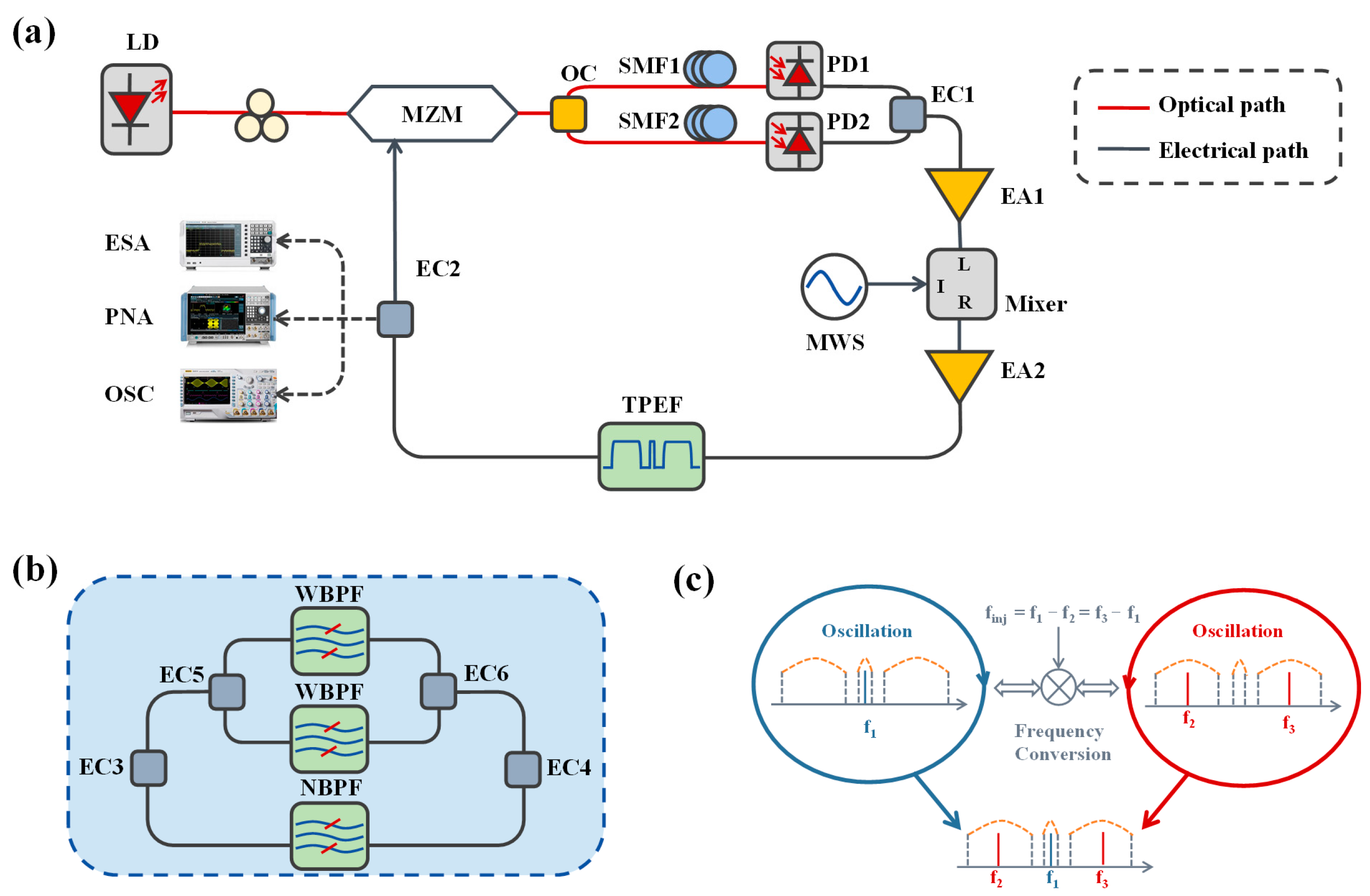
Figure 1a displays the configuration diagram of the coherent tri-frequency microwave signals generation system using an OEO. A continuous wave (CW) light provided by a laser diode (LD) carries the oscillation signal fed back from the OEO loop by a Mach–Zehnder modulator (MZM). The MZM is biased at a quadrature point. The modulated optical signal is split into two paths by a 3 dB optical coupler (OC) and goes through two single-mode fibers (SMF1 and SMF2, respectively) of different lengths. They are converted into electrical signals by two photodetectors (PD1 and PD2, respectively). The converted electrical signals are combined by an electrical coupler (EC1). In this way, a dual-loop OEO is built. The dual-loop OEO can effectively suppress supermode noise [
22]. A microwave mixer is inserted into the loop to perform signal conversion. Two electrical amplifiers (EA1 and EA2, respectively) compensate for the microwave loss of the loop. A tri-passband electrical filter (TPEF) is attached to select the signal of interest. The TPEF consists of a narrow passband in the middle and two wide passbands on both sides. The TPEF is implemented using three individual electrical filters and electrical couplers (EC3, EC4, EC5, and EC6, respectively), as shown in
Figure 1b. Another electrical coupler, EC2, is used to couple the generated signal out of the OEO loop.
The OEO loop starts oscillation at the central frequency of the narrow passband of the TPEF. A single-tone microwave signal
f1 is, thus, generated. By injecting an external microwave signal
finj to the microwave mixer, frequency down- and up-converted signals are generated at
f2 =
f1 −
finj and
f3 =
f1 +
finj, respectively. Both newly generated frequency components pass through two wide passbands of the TPEF, and are thus allowed to oscillate in the OEO loop. In addition, the two generated signals are frequency tunable within the two wide passbands by varying the frequency of the injected signal
finj. In the loop,
f2 and
f3 also, respectively, mix with the external injected signal
finj and generate a microwave signal at
f1, that is,
f1 =
f2 +
finj and
f1 =
f3 −
finj, as shown in
Figure 1c. Consequently, these three microwave signals are phase-locked by the frequency mutual injection process. The proposed method is theoretically scalable to four or more frequency components by widening the passbands of the TPEF to allow higher-order mixing products to pass through. However, due to mixer conversion loss, higher-order signals have reduced power, potentially leading to amplitude imbalance and reduced stability.
Mathematically, the output optical field of MZM can be expressed as
where
E0 and
f0 are the amplitude and frequency of the continuous wave (CW) light, respectively;
Vbias,
Vπ, and
Vπ0 are the bias voltage, half-wave voltage at oscillation frequency, and direct-current (DC), respectively;
f1 and
φ1 are the initial frequency and phase of the free running oscillation in the OEO;
f2 =
f1 −
finj and
f3 =
f1 +
finj are the frequency of the generated signals by frequency mixing of the injected signal
finj;
V1,
V2, and
V3 are the amplitudes of the microwave signals at
f1,
f2, and
f3, respectively;
φ1,
φ2, and
φ3 are their initial phases. After photodetection, the microwave signal under the small-signal modulation condition is calculated to be
where
Jn(*) is the
nth Bessel function;
R is the responsivity of the PD;
η is the total loss of the OEO loop;
P0 is the power of the light wave from the laser source;
m1 = π
V1/
Vπ,
m2 = π
V2/
Vπ and
m3 = π
V3/
Vπ are the modulation indices corresponding to the three oscillating signals, respectively.
The external signal injected into the microwave mixer can be expressed as
where
VDC,
Vinj,
finj, and
φinj are the DC voltage, voltage amplitude, frequency, and phase of the injection signal, respectively. After frequency mixing in the mixer and filtering by filters, the microwave signal feedback to the RF port of the MZM is written as
As derived in Equation (4), the output signal comprises three oscillation frequencies (
f1,
f2, and
f3, respectively) and their down- and up-converted microwave signals. When the injection signal
finj =
f1 −
f2 =
f3 −
f1 is introduced to the OEO loop, the oscillating signal at
f1 is injected into
f2 and
f3 by frequency mixing in the microwave mixer. Similarly, the signals at
f2 and
f3 are coupled to
f1 by mixing with
finj. Mutual frequency injection and phase locking among these three signals occur, as illustrated in
Figure 1c. The tri-frequency signal is frequency tunable within the passband of the TPEF by adjusting
finj, with
f2 and
f3 tracking
finj linearly as
f2 =
f1 −
finj and
f3 =
f1 +
finj.
3. Experiments and Results
A proof-of-concept experiment was conducted based on the configuration depicted in
Figure 1a. An LD (NKT Photonics, Koheras Adjustuk) was utilized to generate a CW light at 1550 nm. An MZM (Fujitsu FTM7938EZ) biased at a quadrature point was employed to modulate the CW light by the feedback oscillation signal. Two SMFs (SMF1 and SMF2) of 2 km and 300 m, respectively, were used to build a dual-loop OEO. Two photodetectors (PD1 and PD2) with a 3 dB bandwidth of 18 GHz converted optical signals into electrical signals. Two EAs (EA1 and EA2) with gains of 38 dB and 30 dB were utilized to compensate for the loss of the loop. The externally injected microwave signal was provided by a microwave source (Agilent E8257D). In principle, a customized TPEF should be used in our experiment. However, such TPEF was unavailable in our lab. Alternatively, three electrical filters were connected as shown in
Figure 1a to perform the same functionality. Here, we used a narrow passband electrical filter centered at 14 GHz with a 3 dB bandwidth of 40 MHz, and two wide passband electrical filters centered at 10 GHz and 18 GHz, respectively, with a 3 dB bandwidth of 4 GHz. An electrical spectrum analyzer (ESA) was utilized to observe the spectrum of the generated microwave signal. A phase noise analyzer and an oscilloscope were employed to measure the phase noise and capture the time–domain waveform of the microwave signal.
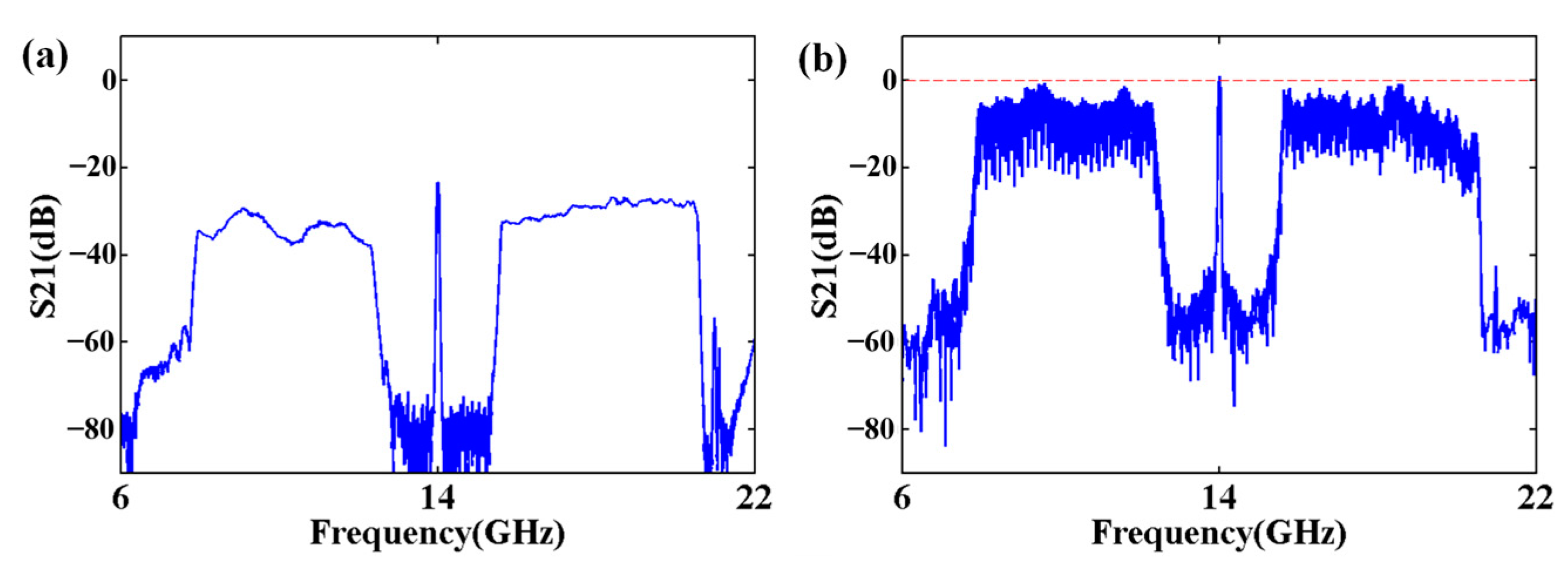
Figure 2a depicts the magnitude response of the TPEF. The TPEF has two wide passbands from 8 to 12 GHz and 16 to 20 GHz, respectively, as well as a narrow passband with a bandwidth of 40 MHz and a central frequency of 14 GHz. Differences in their magnitude responses lead to a power imbalance, which may slightly affect phase noise but remains within acceptable limits. Although the group delay across the three filters is not perfectly matched, the variation is small and has a negligible impact on coherence. If needed, adjustable microwave delay lines can be introduced to further improve group delay matching and system performance.
Figure 2b displays the open-loop magnitude response of the OEO. In the measurement, the input and output ports of the vector network analyzer (VNA) are connected to the output of the TPEF and the RF port of the MZM, respectively. It is noted that the magnitude response of the narrow passband is slightly higher than both of the two wide passbands and remains above 0 dB, satisfying the oscillation condition of the OEO cavity. The red line marks the position of 0 dB. It ensures that the OEO cavity oscillates at a fixed frequency of 14 GHz.
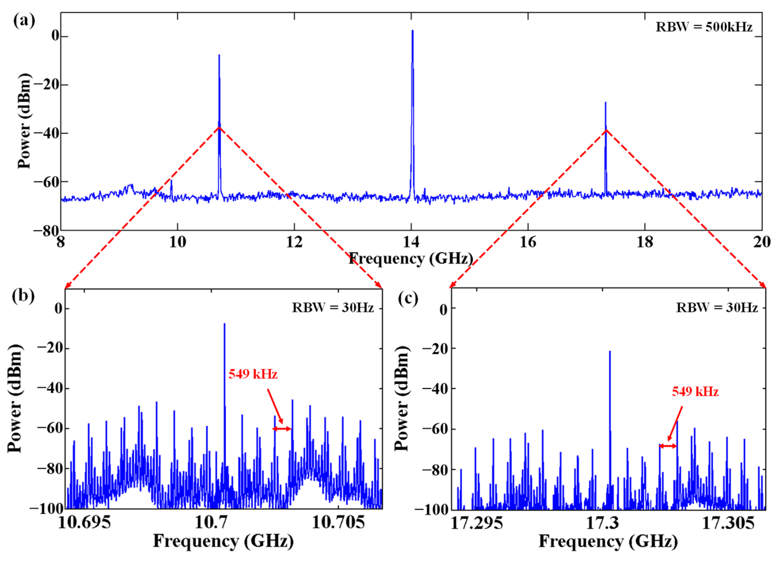
Without external RF injection, the OEO loop starts oscillation at a single frequency of 14 GHz, as shown in
Figure 3a, which is selected by the narrow passband of the TPEF.
Figure 3b shows the zoom-in view of
Figure 3a with a spectrum bandwidth of 10 MHz. The SMSR exceeds 40 dB. The free spectrum range (FSR) of the modes is 549 kHz, which is determined by the dual-loop, as mentioned in [
22]. Due to the Vernier effect, part of the modes in the long loop are strongly suppressed. If the loop length is further adjusted or the Vernier effect and PT-symmetric OEO [
23] are combined, the SMSR of the system can be further improved. Next, an external microwave signal at 3.3 GHz was injected into the OEO loop from the microwave mixer, and new microwave signals at 10.7 GHz and 17.3 GHz were generated by the frequency mixing process, as shown in
Figure 4a. These microwave signals, along with the initial microwave signal at 14 GHz, simultaneously oscillate in the OEO loop. The injected signal at 3.3 GHz was filtered out by the TPEF. The fluctuations of the noise floor of the tri-frequency signals in
Figure 3b and
Figure 4b exhibit a high degree of consistency. The similar noise floor fluctuations observed primarily originate from the 14 GHz microwave signal, whose noise is transferred to the other frequency components through mixing and mutual injection locking. These fluctuations are mainly caused by the non-ideal magnitude response of the TPEF and further amplified by the uneven frequency responses of system components.
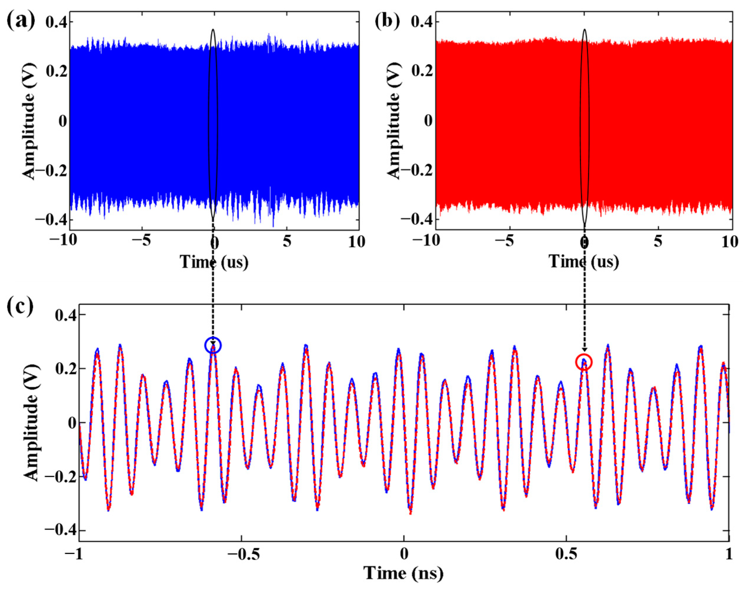
To verify the coherence of the generated tri-frequency microwave signal, we recorded two time–domain waveforms at a time interval of 120 s, as shown in
Figure 5a,b. The overlapped and zoomed-in view of the two time–domain waveforms, represented by blue and red lines, respectively, is shown in
Figure 5c. Due to the frequency mixing and mutual injection locking mechanism, the three frequency components are phase-locked, thereby suppressing frequency drift and ensuring the stability of the system. As shown in
Figure 5c, the signals overlap perfectly, which indicates that these three frequency components are coherent; otherwise, the measured waveforms would vary with time.
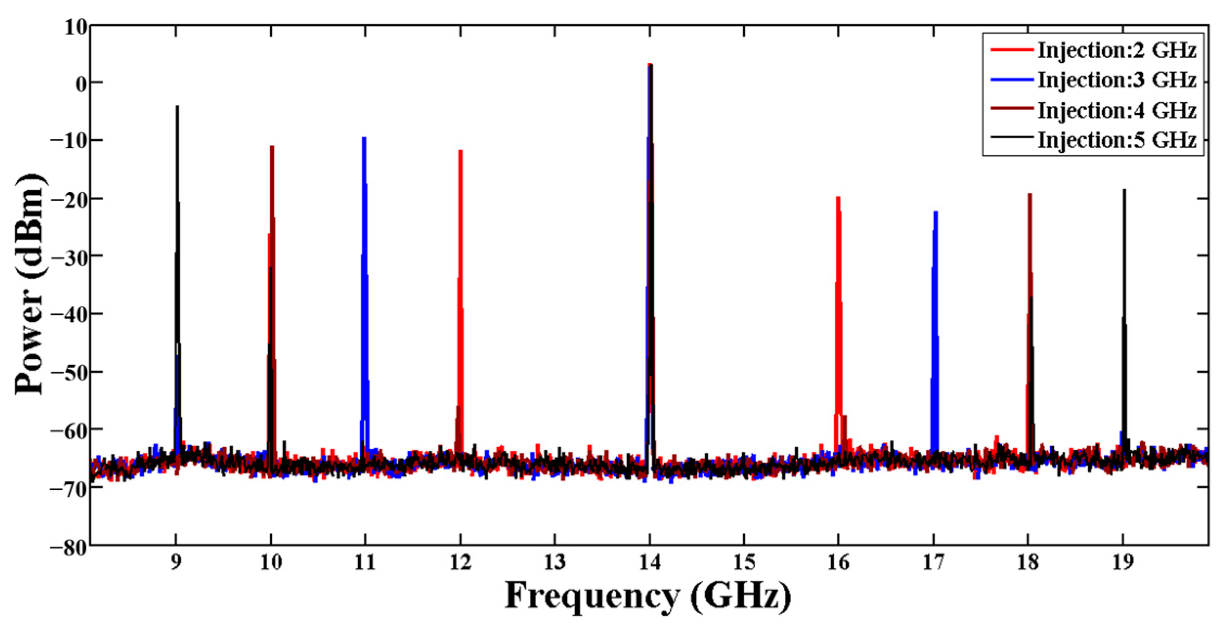
Figure 6 illustrates the electrical spectra of the coherent tri-frequency microwave signals under external microwave signal injection at different frequencies from 2 to 5 GHz. As can be seen, newly generated microwave components are tuned from 9 to 12 GHz and from 16 to 19 GHz, respectively. The power of these frequency components fluctuates slightly due to the uneven magnitude response of the TPEF and the OEO loop, as shown in
Figure 2. For certain practical applications (such as multi-band radar systems), this power non-uniformity may have a slight impact on system performance. To address this issue, gain equalization can be implemented after each filter to compensate for signal attenuation. Furthermore, if passbands with similar frequency responses were used, the power flatness of different frequency components would not be affected by gain competition in the OEO loop due to the mutual injection locking mechanism.
The single-sideband phase noise (PN) spectra of the generated coherent tri-frequency microwave signals with external microwave signal injection from 2 to 5 GHz were measured and evaluated, as shown in
Figure 7a–d. The phase noise of the generated tri-frequency microwave signals is around −110 dBc/Hz@10 kHz. Actually, compared to the state-of-the-art dual-frequency OEO systems [
21,
24], the phase noise performance is relatively poor due to the high relative intensity noise (RIN) of the laser source and the noise from EAs. It can be further improved by employing low-RIN and high-quality continuous-wave laser sources, reducing loop loss, utilizing low-noise and highly linear microwave mixers, and limiting the residual additive noise introduced by the intra-cavity active devices, as described in [
25,
26]. The phase noises of three microwave components are quite similar at near-end frequency offset, confirming that the tri-frequency microwave signals generated by this system have good stability. However, the two newly generated components fluctuate at the far end frequency offset. This phenomenon can be attributed to the different losses of these three components, which is shown in
Figure 2b. Their phase noise should overlap perfectly for the same loss condition, as reported in [
20]. For the same reason, their phase noise is also different for external microwave injection at different frequencies with the same injection power, as shown in
Figure 7a–d. This problem can be overcome by tuning the injection power for different injection frequencies. Alternatively, we can also try to use two wide passband filters with flat magnitude response.


