Differentially Fed, Wideband Dual-Polarized Filtering Dielectric Resonator Patch Antenna Using a Sequentially Rotated Shorting Coupling Structure


Abstract
1. Introduction
2. Antenna Design Process and Analysis
- (1)
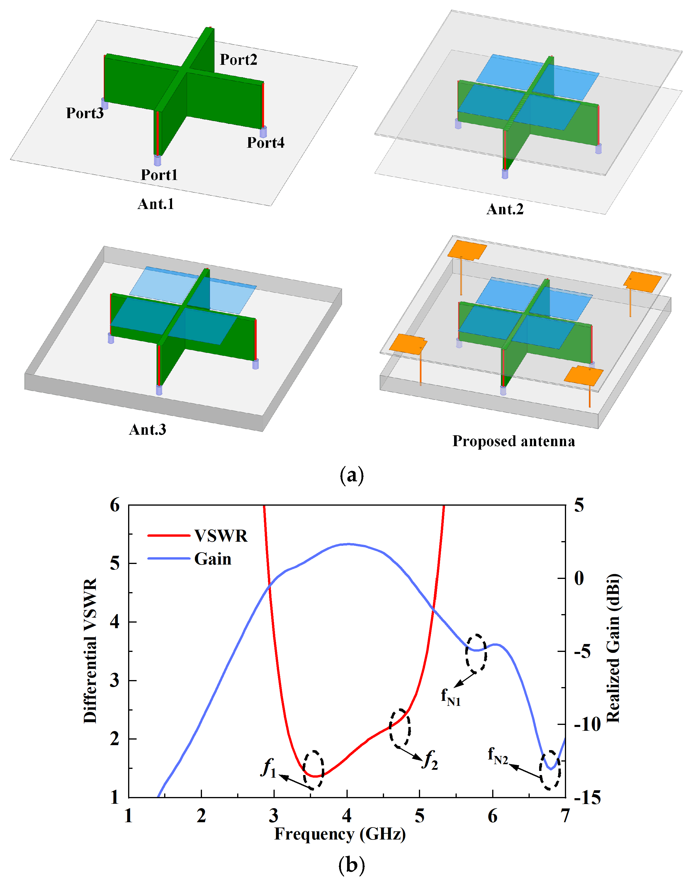
- Reference Antenna 1
- (2)
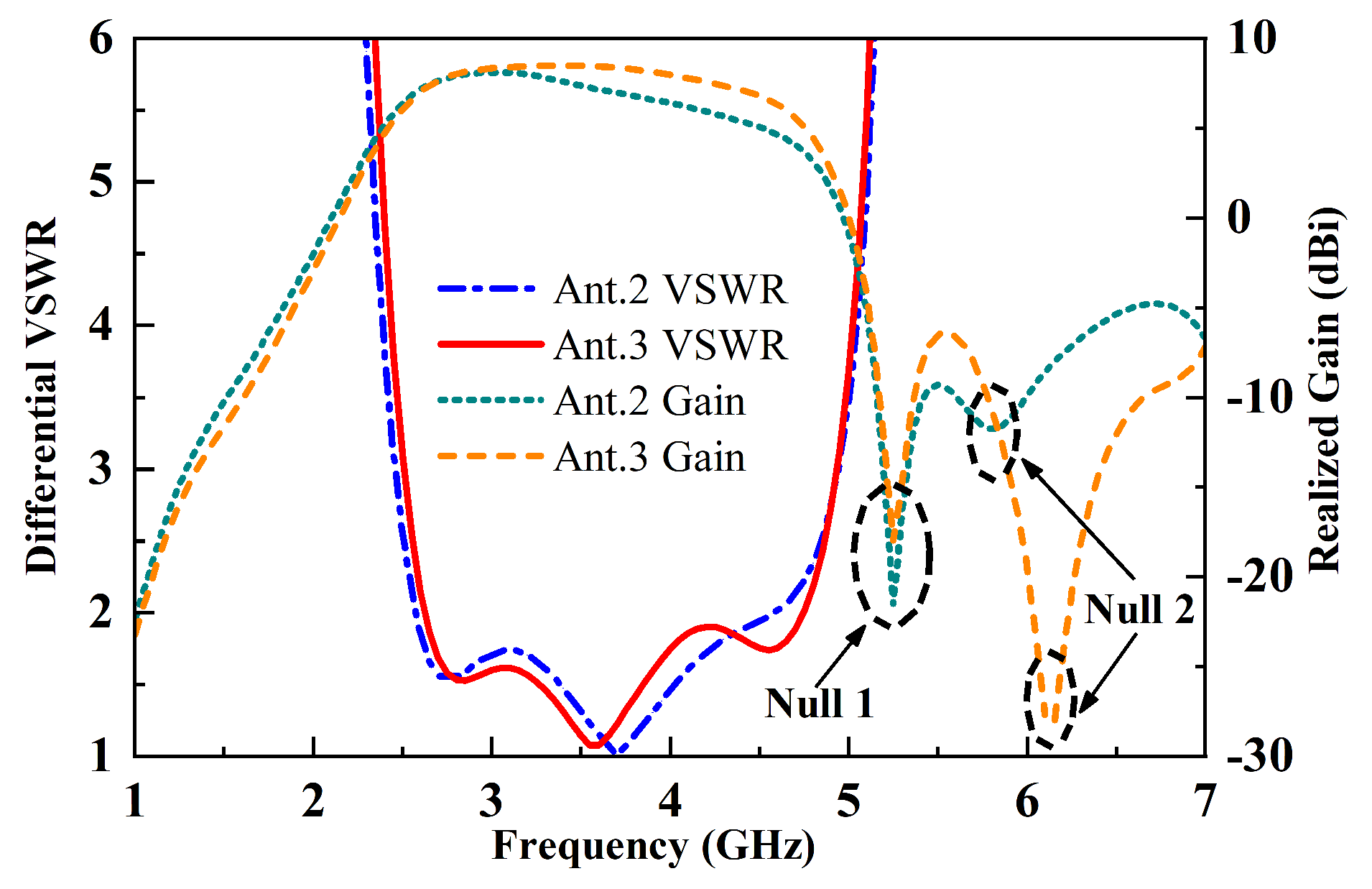
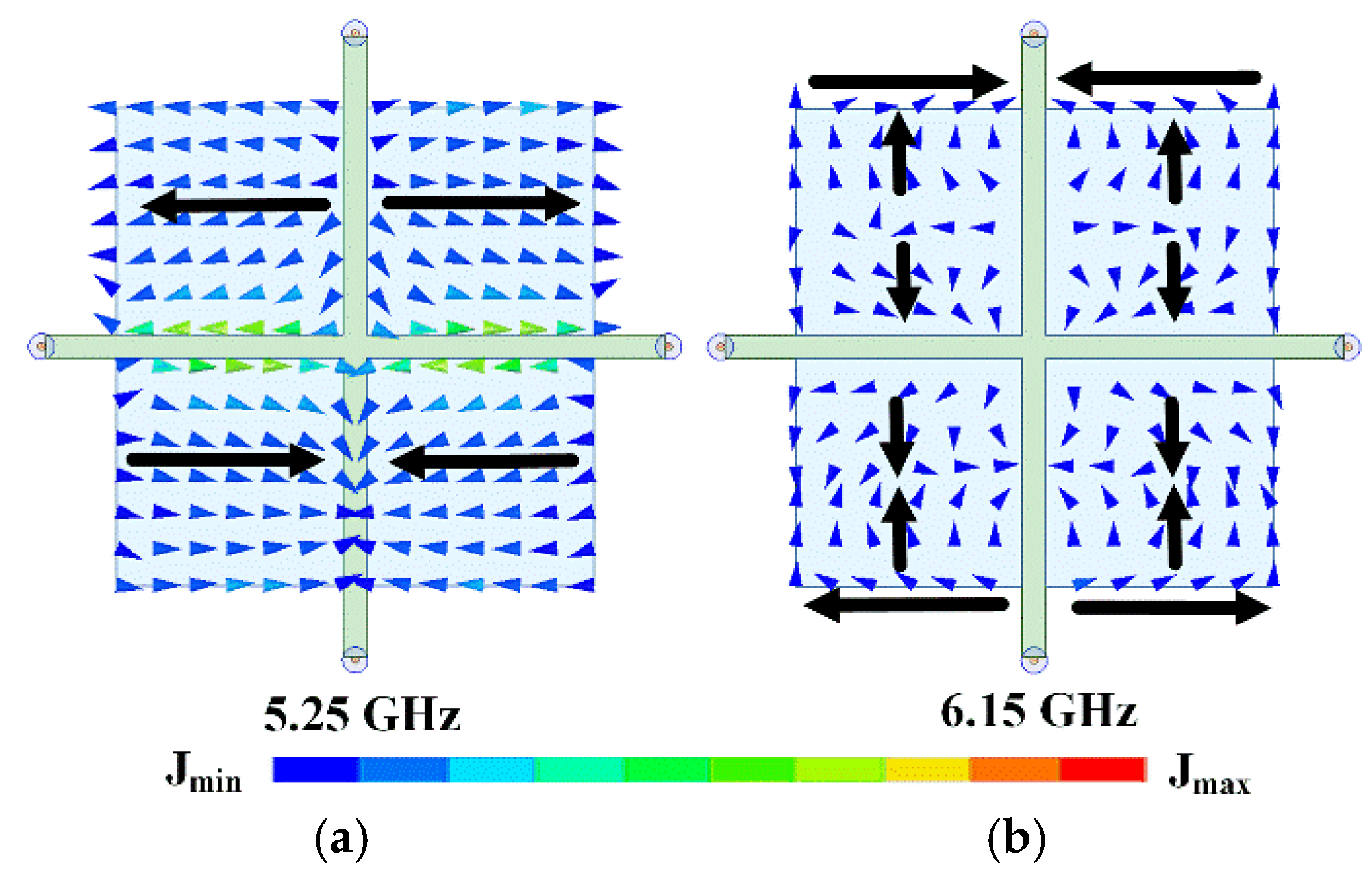
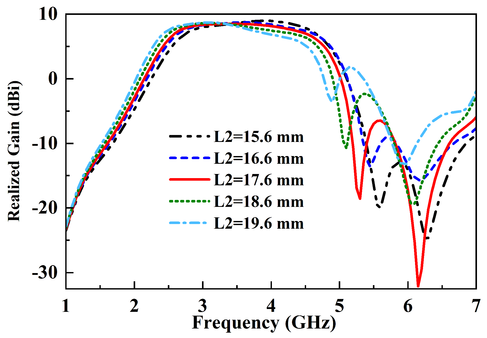
- Reference Antenna 2 and Antenna 3
- (3)
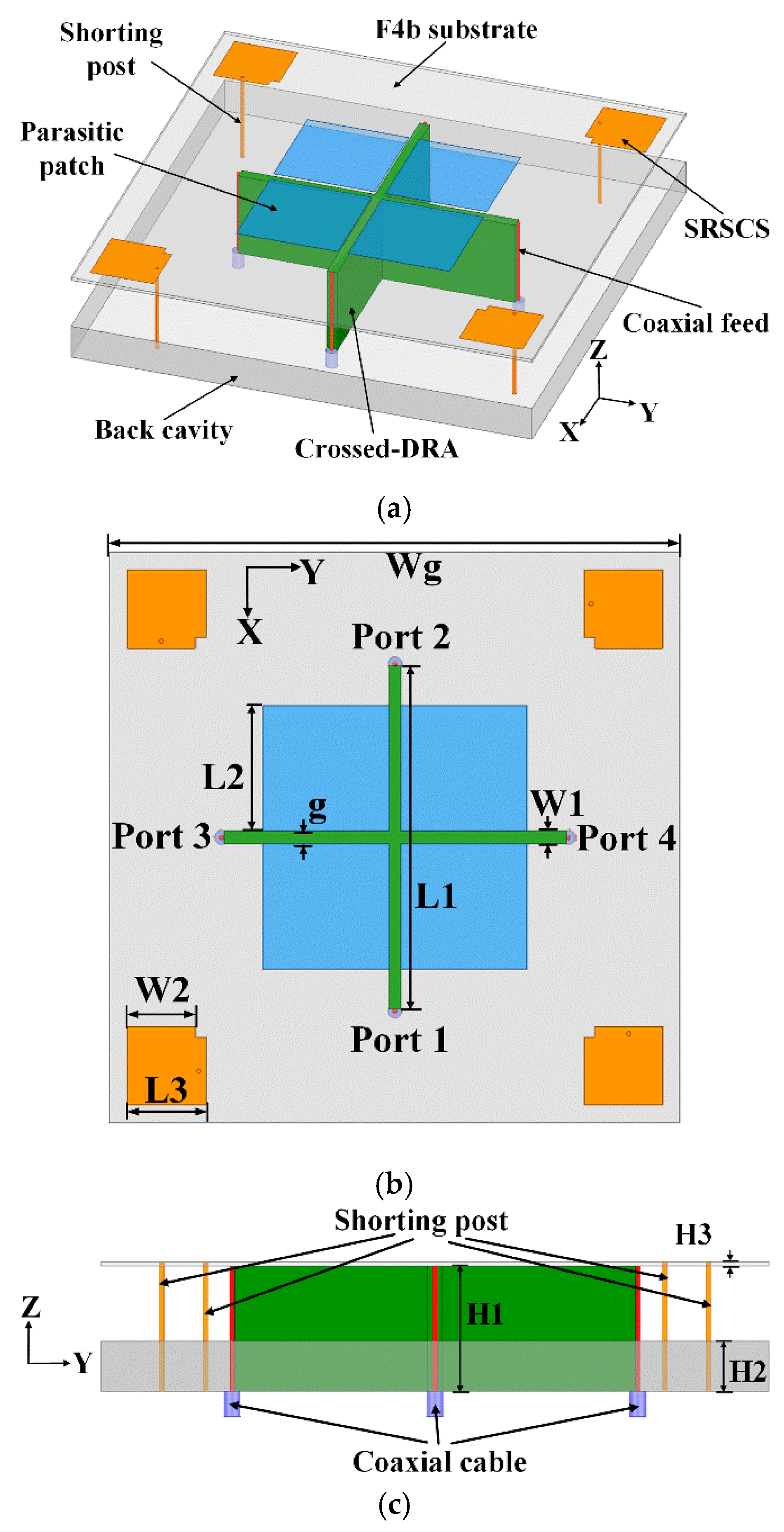
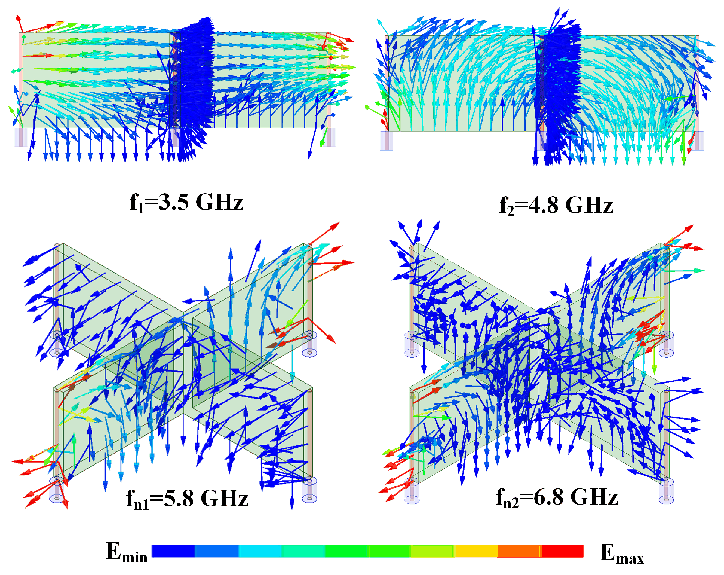
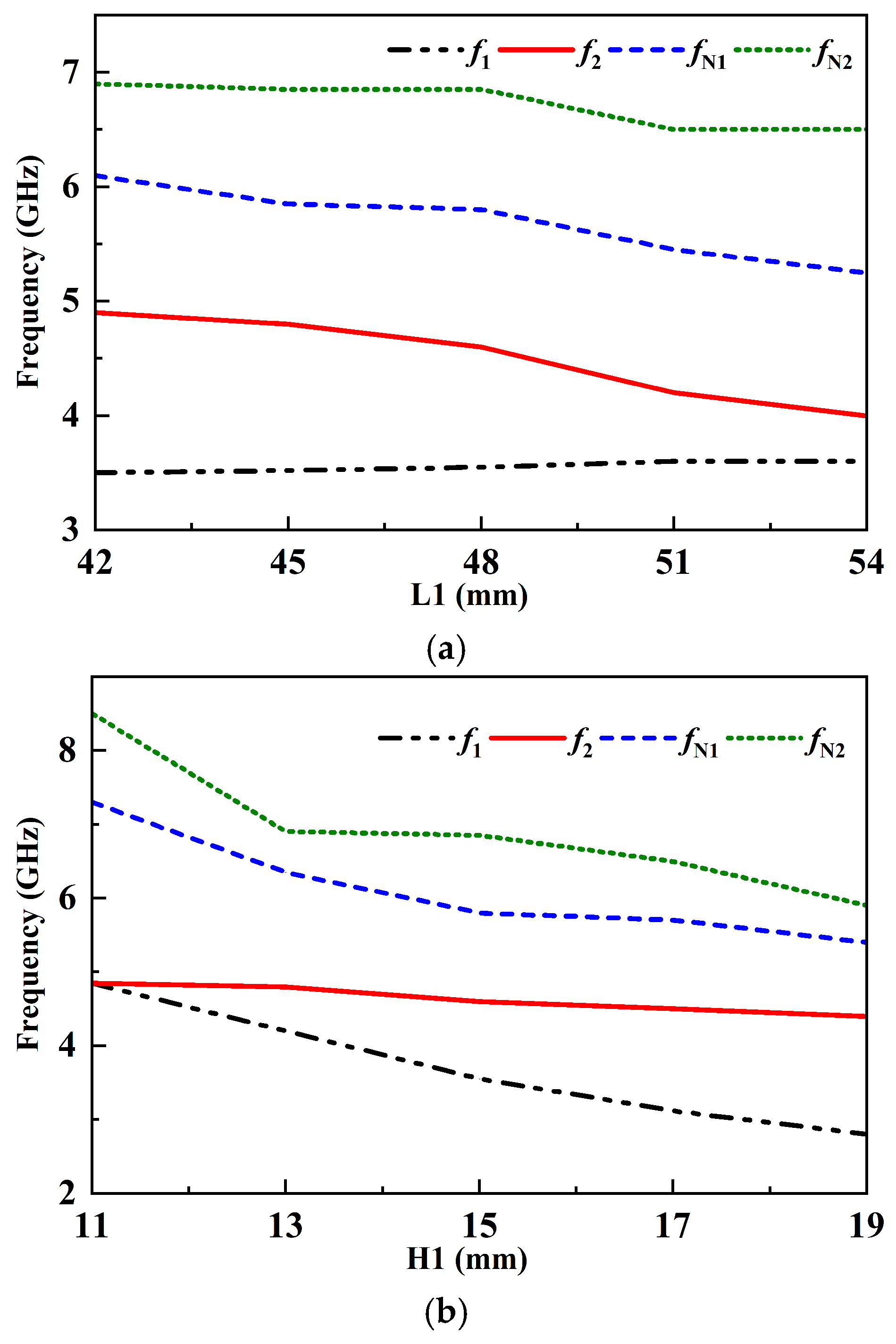
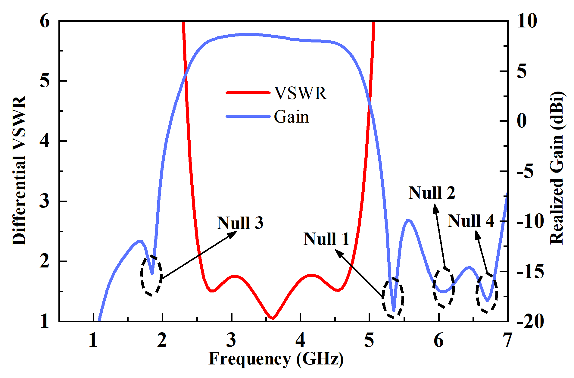
- The proposed antenna
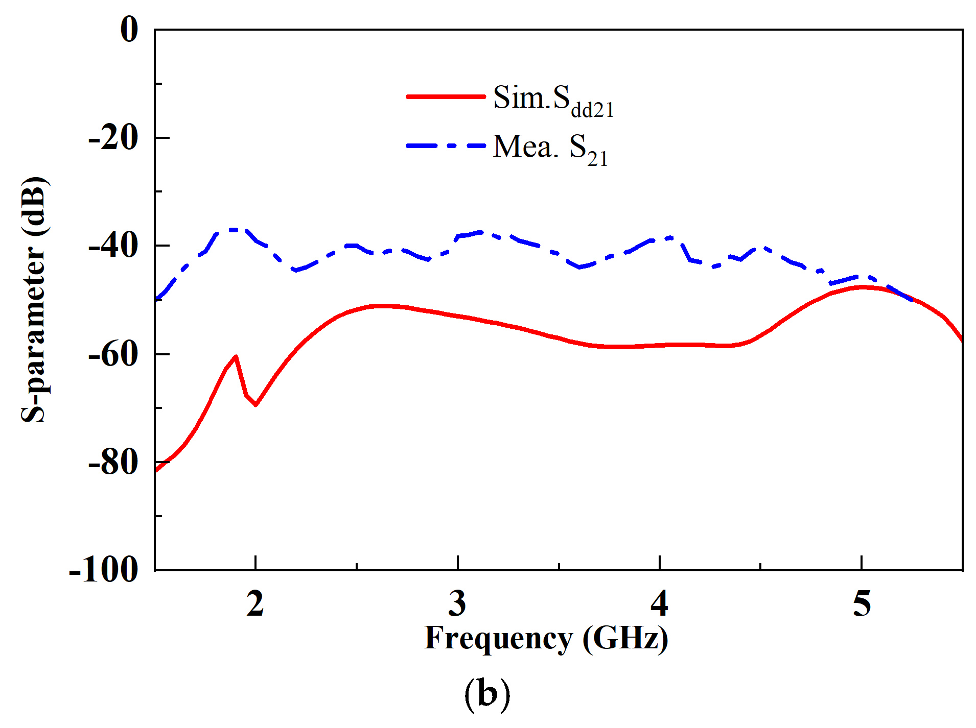
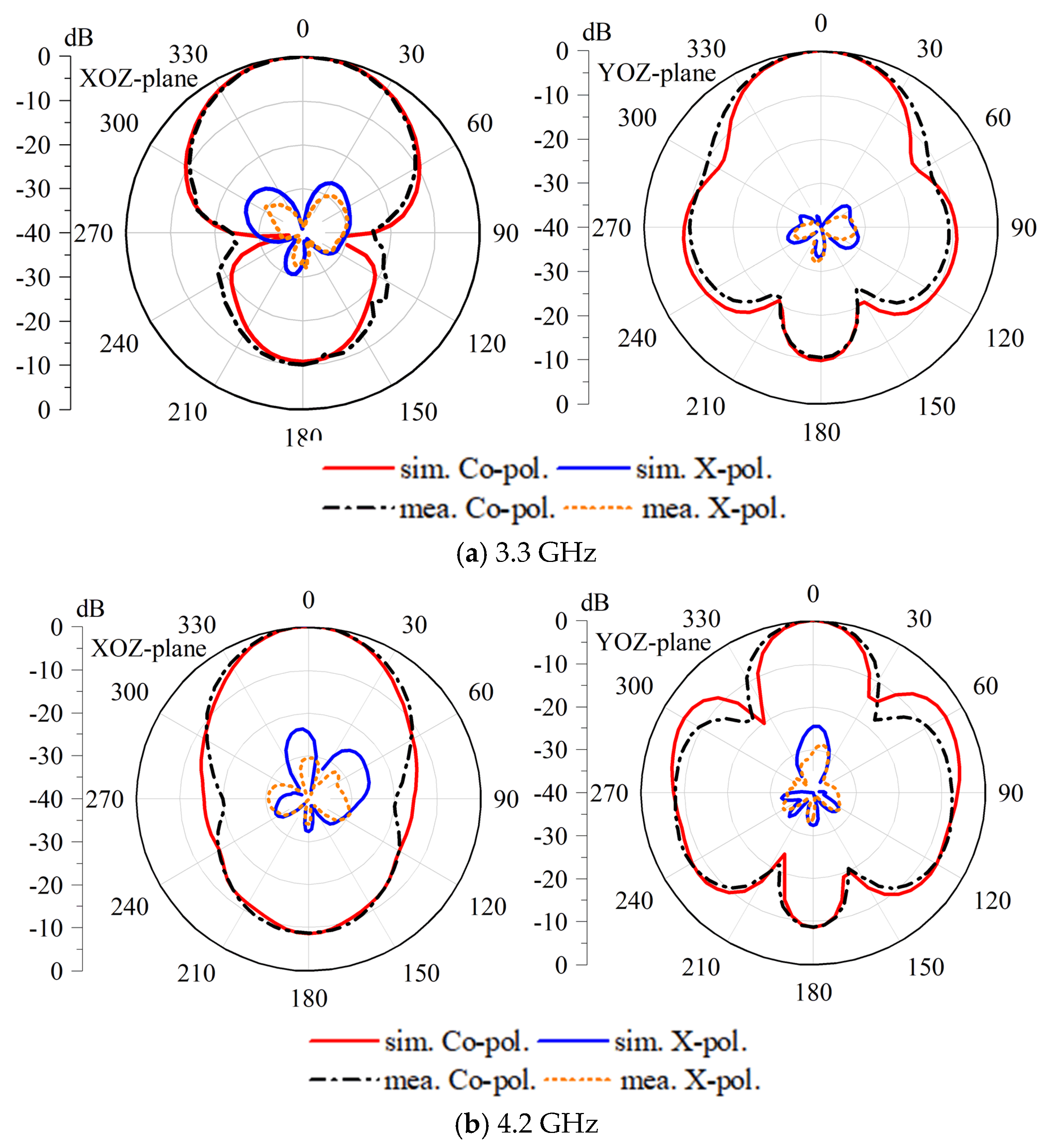
3. Experimental Results and Discussion
4. Conclusions
Author Contributions
Funding
Institutional Review Board Statement
Informed Consent Statement
Data Availability Statement
Conflicts of Interest
References
- Xu, H.-X.; Wang, S.; Wang, C.; Wang, M.; Wang, Y.; Peng, Q. Polarization-Insensitive Metalens and Its Applications to Reflectarrays with Polarization Diversity. IEEE Trans. Antennas Propag. 2022, 70, 1895–1905. [Google Scholar] [CrossRef]
- Cui, Y.; Gao, X.; Li, R. A Broadband Differentially-Fed Dual-Polarized Planar Antenna. IEEE Trans. Antennas Propag. 2017, 65, 3231–3234. [Google Scholar] [CrossRef]
- Wen, D.L.; Zheng, D.Z.; Chu, Q.X. A Wideband Differentially-Fed Dual-Polarized Antenna with Stable Radiation Pattern for Base Stations. IEEE Trans. Antennas Propag. 2017, 65, 2248–2255. [Google Scholar] [CrossRef]
- Mao, C.X.; Gao, S.; Wang, Y.; Luo, Q.; Chu, Q.X. A Shared-Aperture Dual-Band Dual-Polarized Filtering-Antenna-Array with Improved Frequency Response. IEEE Trans. Antennas Propag. 2017, 65, 1836–1844. [Google Scholar] [CrossRef]
- Li, L.; Xiong, H.D.; Wu, W.Y.; Fu, A.B.; Han, J.Y. A T-Shaped Strips Loaded Wideband Filtering Patch Antenna with High Selectivity. IEEE Antennas Wirel. Propag. Lett. 2024, 23, 89–93. [Google Scholar] [CrossRef]
- Wu, R.; Wen, G.H.; Chen, F.C.; Li, J.F.; Ye, L.H.; Cao, W.P. A Low-Profile Broadband Filtering Antenna and Its Array for 5G Applications. IEEE Antennas Wirel. Propag. Lett. 2024, 23, 2920–2924. [Google Scholar] [CrossRef]
- Wu, Q.-S.; Zhang, X.; Zhu, L. Co-Design of a Wideband Circularly Polarized Filtering Patch Antenna with Three Minima in Axial Ratio Response. IEEE Trans. Antennas Propag. 2018, 66, 5022–5030. [Google Scholar] [CrossRef]
- Guo, J.; Chen, Y.; Yang, D.; Sun, K.; Pan, J.; Liu, S. Design of Wideband Filtering Patch Antenna Array with High Aperture Efficiency and Good Filtering Performance. IEEE Trans. Antennas Propag. 2024, 72, 974–979. [Google Scholar] [CrossRef]
- Tang, H.; Chen, J.; Yang, W.; Zhou, L.; Li, W. Differential Dual-Band Dual-Polarized Dielectric Resonator Antenna. IEEE Trans. Antennas Propag. 2017, 65, 855–860. [Google Scholar] [CrossRef]
- Li, D.; Yang, C.; Shi, L.; Liu, Y.; Chen, Q.; Shinohara, N. A High-Gain Filtering Quasi-Yagi Antenna Based on Compressed Third-Order Mode Dipole. IEEE Antennas Wirel. Propag. Lett. 2024, 23, 2860–2864. [Google Scholar] [CrossRef]
- Li, Y.; Zhao, Z.; Tang, Z.; Yin, Y. Differentially Fed, Dual-Band Dual-Polarized Filtering Antenna with High Selectivity for 5G Sub-6 GHz Base Station Applications. IEEE Trans. Antennas Propag. 2020, 68, 3231–3236. [Google Scholar] [CrossRef]
- Hu, P.F.; Pan, Y.M.; Zhang, X.Y.; Hu, B.-J. A Filtering Patch Antenna with Reconfigurable Frequency and Bandwidth Using F-Shaped Probe. IEEE Trans. Antennas Propag. 2019, 67, 121–130. [Google Scholar] [CrossRef]
- Qian, J.-F.; Chen, F.-C.; Chu, Q.-X.; Xue, Q.; Lancaster, M.J. A Novel Electric and Magnetic Gap-Coupled Broadband Patch Antenna with Improved Selectivity and Its Application in MIMO System. IEEE Trans. Antennas Propag. 2018, 66, 5625–5629. [Google Scholar] [CrossRef]
- Ding, C.F.; Zhang, X.Y.; Zhang, Y.; Pan, Y.M.; Xue, Q. Compact Broadband Dual-Polarized Filtering Dipole Antenna with High Selectivity for Base-Station Applications. IEEE Trans. Antennas Propag. 2018, 66, 5747–5756. [Google Scholar] [CrossRef]
- Jin, J.Y.; Liao, S.; Xue, Q. Design of Filtering-Radiating Patch Antennas with Tunable Radiation Nulls for High Selectivity. IEEE Trans. Antennas Propag. 2018, 66, 2125–2130. [Google Scholar] [CrossRef]
- Zhang, Y.; Zhang, X.Y.; Ye, L.-H.; Pan, Y.-M. Dual-Band Base Station Array Using Filtering Antenna Elements for Mutual Coupling Suppression. IEEE Trans. Antennas Propag. 2016, 64, 3423–3430. [Google Scholar] [CrossRef]
- Yang, W.; Xun, M.; Che, W.; Feng, W.; Zhang, Y.; Xue, Q. Novel Compact High-Gain Differential-Fed Dual-Polarized Filtering Patch Antenna. IEEE Trans. Antennas Propag. 2019, 67, 7261–7271. [Google Scholar] [CrossRef]
- Liu, Y.-T.; Leung, K.W.; Yang, N. Compact Absorptive Filtering Patch Antenna. IEEE Trans. Antennas Propag. 2020, 68, 633–642. [Google Scholar] [CrossRef]
- Fang, X.S.; Shi, K.P.; Sun, Y.X. Design of the Single-/Dual-Port Wideband Differential Dielectric Resonator Antenna Using Higher Order Mode. IEEE Antennas Wirel. Propag. Lett. 2020, 19, 1605–1609. [Google Scholar] [CrossRef]
- Wang, X.-Y.; Tang, S.-C.; Yang, L.-L.; Chen, J.-X. Differential-Fed Dual-Polarized Dielectric Patch Antenna with Gain Enhancement Based on Higher Order Modes. IEEE Antennas Wirel. Propag. Lett. 2020, 19, 502–506. [Google Scholar] [CrossRef]
- Xu, H.X.; Wang, G.M.; Qi, M.Q.; Zhang, C.X.; Liang, J.G.; Gong, J.Q.; Zhou, Y.C. Analysis and Design of Two-Dimensional Resonant-Type Composite Right/Left-Handed Transmission Lines with Compact Gain-Enhanced Resonant Antennas. IEEE Trans. Antennas Propag. 2013, 61, 735–747. [Google Scholar] [CrossRef]

Disclaimer/Publisher’s Note: The statements, opinions and data contained in all publications are solely those of the individual author(s) and contributor(s) and not of MDPI and/or the editor(s). MDPI and/or the editor(s) disclaim responsibility for any injury to people or property resulting from any ideas, methods, instructions or products referred to in the content. |
© 2025 by the authors. Licensee MDPI, Basel, Switzerland. This article is an open access article distributed under the terms and conditions of the Creative Commons Attribution (CC BY) license (https://creativecommons.org/licenses/by/4.0/).
Share and Cite
Song, H.; Duan, B.; Zhang, F. Differentially Fed, Wideband Dual-Polarized Filtering Dielectric Resonator Patch Antenna Using a Sequentially Rotated Shorting Coupling Structure. Photonics 2025, 12, 239. https://doi.org/10.3390/photonics12030239
Song H, Duan B, Zhang F. Differentially Fed, Wideband Dual-Polarized Filtering Dielectric Resonator Patch Antenna Using a Sequentially Rotated Shorting Coupling Structure. Photonics. 2025; 12(3):239. https://doi.org/10.3390/photonics12030239
Chicago/Turabian StyleSong, Haitao, Baoxing Duan, and Feifei Zhang. 2025. "Differentially Fed, Wideband Dual-Polarized Filtering Dielectric Resonator Patch Antenna Using a Sequentially Rotated Shorting Coupling Structure" Photonics 12, no. 3: 239. https://doi.org/10.3390/photonics12030239
APA StyleSong, H., Duan, B., & Zhang, F. (2025). Differentially Fed, Wideband Dual-Polarized Filtering Dielectric Resonator Patch Antenna Using a Sequentially Rotated Shorting Coupling Structure. Photonics, 12(3), 239. https://doi.org/10.3390/photonics12030239