Abstract
A short-circuited coupling structure (SCCS) is proposed to obtain a gain-filtering response for dual-polarized antennas. A conventional dipole is designed with two intrinsic radiation nulls. By introducing an SCCS, an additional radiation null is obtained, and the impedance bandwidth of an antenna can be further improved. Based on this design principle, two dual-polarized filtering antennas are designed for 4G and 5G wireless communication devices. The impedance bandwidth of the proposed 4G filtering antenna is 1.63–2.97 GHz (|S11| < −15 dB), with four radiation nulls at 1.1 GHz, 3.25 GHz, 3.5 GHz, and 4.0 GHz. The impedance bandwidth of the proposed 5G filtering antenna is 3.23–4.21 GHz (|S33| < −15 dB), with four radiation nulls at 1.7 GHz, 2.5 GHz, 3 GHz, and 4.6 GHz. Further, the decoupling function of the SCCS on 4G/5G MIMO antenna designs is also discussed. When introducing an SCCS, the port isolation levels of two elements between the 4G and 5G antennas, as well as the adjacent 5G antennas, can be improved by 14 dB and 6 dB, respectively. The port isolation levels of five elements between the 4G and 5G antennas, as well as the adjacent 5G antennas, can be improved by 15.2 dB and 9.5 dB, respectively. This technique could also be a potential candidate for optical antenna designs in optical front-ends and other multi-wavelength fiber lasers with microstructures.
1. Introduction
In modern wireless communication devices, the coexistence of multi-band and multi-generation antennas has become the mainstream development trend. Therefore, the suppression of the out-of-band in antennas has attracted increasing attention.
In recent years, scholars have conducted a lot of research on filtering antennas. One approach that has been explored is integrating filters into antenna feedlines [1,2,3,4]. For example, a stub-loaded resonator (SLR) has been proposed in the literature [2]. By integrating dual-mode resonators into a U-slot patch antenna, a dual-band bandpass filtering response of the radiation gain in both of the two bands was obtained. Later, in order to simplify the design of filtering antennas, scholars proposed novel feed structures [5,6,7,8,9,10] or chose ones with inherent filtering properties [11,12] to realize a filtered response. For example, hybrid feeders (T-shaped feeding structures and shorting posts) were proposed in [7]; the metallized holes and T-shaped feeder generate radiation nulls in the low-frequency and high-frequency bands, respectively. And when a metallized hole is loaded and an additional radiation null is introduced, this can suppress the level in the higher stopband. In the literature [10], the bandpass radiation response is obtained by the inherent high-pass characteristics of the antenna, along with a straightforward low-pass filtering feeding network. Additionally, the radiation nulls are modulated independently through variations in the electrical length of the ME–dipole and slots.
Furthermore, some scholars have considered introducing radiation nulls using folded dipoles [13], short-circuiting probes [14], parasitic structures [15,16], and slotting [17,18]. For example, the slotted T-branch proposed in [17] and the Defected Ground Structure (DGS) obtained can interfere with the current distribution on microstrip lines and patches at a certain frequency, thereby transmission or radiation nulls were obtained. By adjusting the slots on the T-shaped branch, the radiation nulls can be tuned by the length of the slots.
At present, how to suppress coupling between closely placed antennas in adjacent bands is an urgent issue to be solved. Some techniques have been proposed to deal with the problem [19,20,21,22,23,24]. For example, in the literature [21], a modified metal fence (MMF) was proposed, which can suppress the mutual coupling by 7.6 dB. A partially reflective surface (PRS) was proposed in [24], with the mutual coupling between the two antennas improved by 8.9 dB.
In the above designs, few studies have concerned about the filtering response of radiation gains in MIMO base station antenna designs. In view of this, a short-circuited coupling structure (SCCS) is proposed. An SCCS can not only help generate radiated nulls in filtering antenna designs, but also suppress the mutual coupling between antennas in adjacent bands. Finally, the impedance bandwidth of the proposed filtering antennas can cover 1.7–2.7 GHz for 4G and 3.3–3.8 GHz for 5G base station frequency bands, with four and three radiation nulls in the two bands, respectively. In addition, the isolation levels of 4G antennas with two elements and five elements can be improved by 14 dB and 6 dB, respectively. The isolation levels of two elements and five elements between 5G antenna ports can be improved by 15.2 dB and 9.5 dB, respectively. A comparison indicates that the structure demonstrates favorable applicability, especially when antennas are placed in compact frequency bands.
2. Antenna Design Process and Analysis
2.1. The 4G Antenna Design
Figure 1 illustrates the configuration of the proposed 4G antenna. The antenna is primarily composed of two pairs of crossed dipole antennas, an FR4 substrate (the thickness is 0.8 mm, the relative permittivity is 4.4, and the loss tangent is 0.02), two Y-shaped feeding branches, and a reflector plate. Two sets of crossed dipole antennas are printed on the bottom of the substrate, forming an open-loop antenna structure when the antenna dipole arms are bent inward. Moreover, four SCCSs are printed on the top of the substrate and connected to the ground through the metal posts.
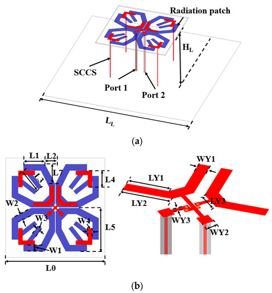
Figure 1.
Configuration of the proposed antenna: (a) perspective view and (b) 3-D top view of the antenna and Y-shaped feeding structure. The optimized parameters are as follows (unit: mm): LL = 130.0, HL = 38.0, L0 = 70.0, L1 = 14.9, L2 = 6.0, L3 = 18.0, L4 = 12.0, L5 = 27.0, W1 = 4.0, W2 = 2.5, W3 = 3.0, W4 = 2.9, L7 = 9.0, WY1 = 2.5, LY1 = 8.0, LY2 = 10.0, WY2 = 2.7, LY3 = 5.0, and WY3 = 0.8.
The evolution process of the 4G antenna is shown in Figure 2. The conventional dual-polarized antenna (4G Ant. 1) is a pair of square-ring dipoles. The 4G Ant. 2 is designed as an open-ring antenna compared to the 4G Ant. 1. The 4G Ant. 3 has four SCCSs added to the 4G Ant. 2. The S-parameter and realized gain of the 4G Ant. 1 and 4G Ant. 2 are shown in Figure 3. The operation band of the 4G Ant. 1 is 1.65–2.3 GHz. In addition, another resonance is observed at 3.9 GHz. Moreover, two radiation nulls are introduced at 0.8 GHz and 3.9 GHz. For the 4G Ant. 2, the impedance bandwidth is extended to 1.7–2.8 GHz (|S11| < −10 dB). Moreover, the radiation nulls can be adjusted at 1.1 GHz and 3.25 GHz, which contributes to an improved out-of-band suppression performance.
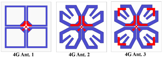
Figure 2.
The evolution process of the 4G antenna.
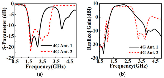
Figure 3.
Simulated (a) S-parameter and (b) realized gain of 4G Ant.1 and Ant. 2.
To further study the mechanism of the radiation nulls, the current distributions on the radiating patch of the 4G Ant. 1 are analyzed. As shown in Figure 4a, when port 1 is excited, the currents on the radiation patch at 0.8 GHz are weak, and the overall currents on the dipole arms cancel out each other (as the dotted red lines shown in Figure 4a), which contributes a radiation null (as shown in Figure 4c). The currents on the radiating patch at 3.9 GHz are strong and the antenna operates at a higher-order resonant mode, as illustrated in Figure 4b. As the currents on the dipole arms are also inverse (as the dotted red lines shown in Figure 4b), the radiation pattern of the antenna shows a fake radiation null.
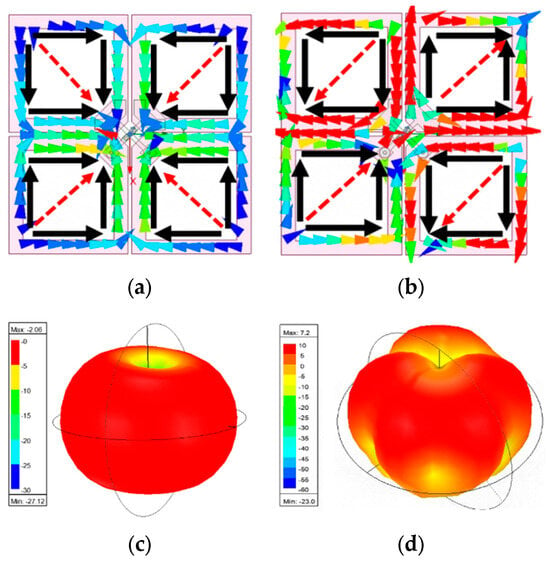
Figure 4.
Current distribution on 4G Ant. 1 at (a) 0.8 GHz and (b) 3.9 GHz. Radiation pattern at (c) 0.8 GHz and (d) 3.9 GHz.
The current distributions on the 4G Ant. 2 at 1.1 GHz and 3.25 GHz are shown in Figure 5. The black arrows represent the main current distributions. The dominant currents on the dipole arm are weak in the corresponding polarization direction and stronger in the other polarization direction. When the current path of the resonant coupling loop is close to a one wavelength, an additional radiation null is introduced at 1.1 GHz. As the current path approaches one wavelength, the symmetrical current loops generated on the dipole arm cancel out, resulting in a radiated null at 1.1 GHz. Similarly, Figure 5b shows the current distribution of the 4G Ant. 2 at 3.25 GHz. The currents are mainly concentrated on the Y-coupled feed structure, while the current on the dipole is weak. This reflects a parallel bilinear effect. Figure 6 shows that the radiation null can be adjusted by changing the length of the dipole arm (L3) and the Y-coupled feed structure (LY2). A radiation null at 3.25 GHz is introduced when the Y-coupled feed structure is about a quarter wavelength.
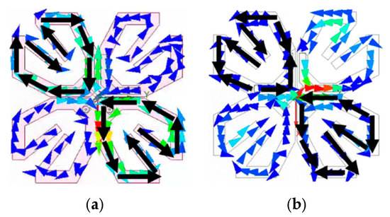
Figure 5.
Current distribution on 4G Ant. 2 at (a) 1.1 GHz and (b) 3.25 GHz.
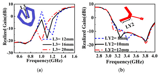
Figure 6.
Realized gain of 4G Ant. 2 varies with (a) dipole arm and (b) Y-shaped feeding structure.
An SCCS is introduced into the 4G Ant. 2 to obtain the 4G Ant. 3. As shown in Figure 7 (black arrows are currents on the radiator, red dotted arrows are overall current distribution), the currents on the open-loop dipole arm are opposite to that on the SCCS, thus generating a radiation gap at 4.0 GHz. Figure 8a shows that the proposed 4G antenna has good impedance matching and out-of-band rejection compared with the 4G Ant. 2, and the impedance bandwidth is improved to 1.63–2.97 GHz (|S11| < −15 dB) and the realized gain of the antenna is 8.5 ± 0.9 dBi (the pink/purple shadow show the operation band of the two antennas). Figure 8b shows that the realized gains of the proposed 4G antenna varies with the SCCS. The frequency of this radiation null can be adjusted by changing the length of the SCCS (L4). Figure 9 shows the radiation patterns of the 4G antenna at 1.7 GHz, 2.2 GHz, and 2.7 GHz. The HPBW of the proposed 4G antenna is 60 ± 5°, with low cross-polarization levels of better than −31 dB.
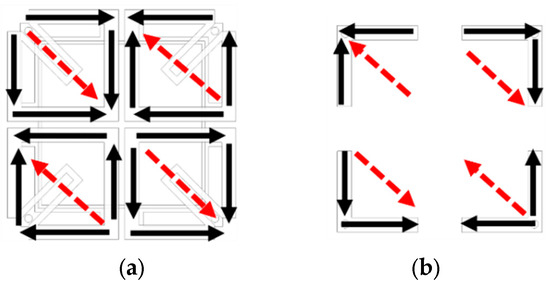
Figure 7.
Current distribution on (a) the radiation patch and (b) the SCCS on the proposed 4G antenna at 4 GHz.
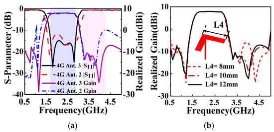
Figure 8.
(a) Simulated results for 4G Ant. 2 and proposed 4G antenna. (b) Realized gain of proposed 4G antenna varies with SCCS.
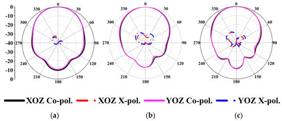
Figure 9.
Simulated radiation patterns of the proposed 4G antenna at (a) 1.7 GHz, (b) 2.2 GHz, and (c) 2.7 GHz.
2.2. The 5G Antenna Design
The structural diagram of the 5G antenna is shown in Figure 10. The design principle is similar to that of the 4G antenna, with the difference being that the 5G antenna utilizes a Balun feed, as depicted in Figure 10c. A radiation patch is printed on the top of the substrate, and a square ring is printed on the bottom of the substrate. Figure 11 shows the evolution of the 5G antennas. In the 5G Ant. 1, the outer side of the main radiating patch is bent inward to form a loop, which allows for the miniaturization of the 5G antenna (0.43 λH × 0.43 λH × 0.17 λH). However, this antenna design has a narrow bandwidth and poor out-of-band rejection, as shown in Figure 12 (the pink/purple shadow show the operation bands of the two antennas). In order to effectively improve the out-of-band rejection of the antenna, a square loop is introduced into the 5G Ant. 1. This modification allows the antenna to produce a radiation null at 2.5 GHz (Figure 12b). However, the bandwidth is still limited. Therefore, an SCCS is loaded onto the antenna to improve the impedance bandwidth of the 5G antenna to 3.23–4.21 GHz (|S11| < −15 dB), and an additional radiation null is generated at 3.0 GHz.
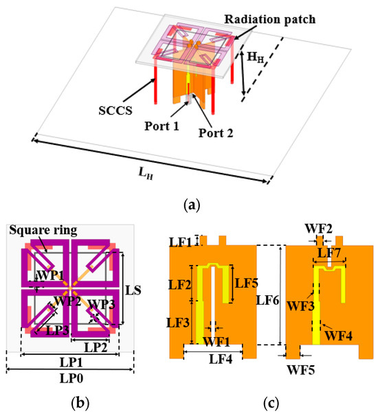
Figure 10.
Configuration of the proposed 5G antenna: (a) perspective view, (b) top view, and (c) Balun. The optimized parameters are as follows (unit: mm): LH = 100.0, HH = 16.0, LP0 = 37.0, LP1 = 26.0, LP2 = 11.0, LP3 = 9.2, WP1 = 1.8, WP2 = 2.4, WP3 = 0.8, LF1 = 2.0, LF2 = 7.5, LF3 = 9.2, LF4 = 10.0, LF5 = 8.0, LF6 = 16.0, LF7 = 7.3, WF1 = 1.0, WF2 = 1.5, WF3 = 1.2, WF4 = 1.7, and WF5 = 4.0.

Figure 11.
The evolution process of the 5G antenna.
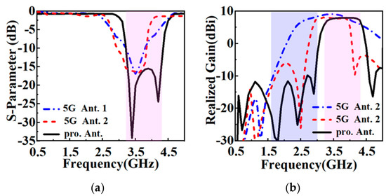
Figure 12.
Simulated (a) S-parameter. (b) Realized gain of 5G Ant. 1, Ant. 2, and Ant. 3.
Figure 13a shows the current distribution of the proposed 5G antenna at 3.0 GHz. The dipole arm and the L-shaped arm generate opposite currents, which cancel each other out; thus, an additional radiation null is introduced. Figure 13b illustrates the impact of the size (L3) of the L-shaped coupling structure on the realized gain. Strong currents are generated when the SCCS current path is approximately a one-fourth wavelength, which effectively mitigates the scattering coupling effect in the 4G band. Finally, the realized gain of the proposed 5G antenna is 8 ± 0.5 dBi. Figure 14 shows the radiation patterns of the proposed 5G antenna. The HPBW of the proposed 5G antenna across the operation band is 61 ± 5°. In addition, low cross-polarization levels of better than −25 dB are also obtained.
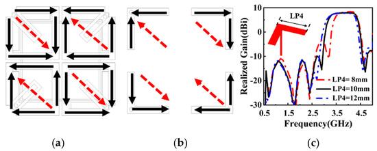
Figure 13.
(a) Current distribution of the proposed 5G antenna at 3 GHz. (b) Current distribution of the SCCS at 3 GHz. (c) Realized gain of the proposed 5G antenna varies with the SCCS.
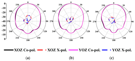
Figure 14.
Simulation radiation patterns of the 5G antenna at (a) 3.4 GHz, (b) 3.6 GHz, and (c) 3.8 GHz.
2.3. Mutual Decoupling of 4G/5G Array with Two Elements
To evaluate the decoupling of the 5G and 4G antennas, Figure 15 illustrates the arrangement of the proposed 4G and 5G antennas positioned adjacent to each other on a reflector plate. The distance between the centers of the antennas is 36 mm (which is equivalent to a wavelength of 0.42 λH at 2.2 GHz). Figure 16 shows the S-parameter and the realized gain of the 4G and 5G antenna elements (the pink/purple shadow show the operation bands of the two antennas). The 4G antenna has a 1.65–2.8 GHz (|S11| < −15 dB) impedance bandwidth and the realized gain is 8.5 ± 0.7 dBi. The impedance bandwidth of the 5G antenna is 3.23–4.1 GHz (|S33| < −15 dB) and the realized gain is 7.7 ± 0.7 dBi. Eventually, the operation band of the proposed 4G antenna is 3.23–4.1 GHz, and the operation band of the proposed 5G antenna is 1.65–2.8 GHz.
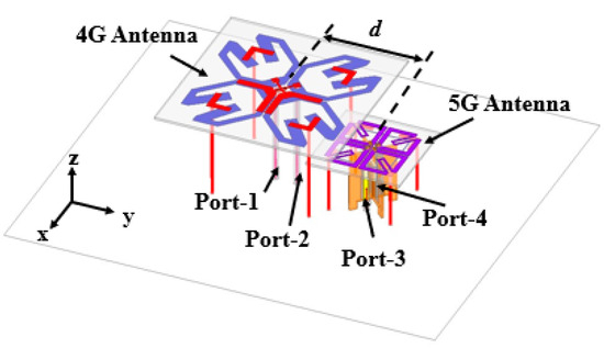
Figure 15.
Configuration of the 4G antenna and 5G antenna with two elements.
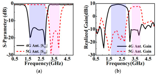
Figure 16.
Simulated (a) S-parameter and (b) realized gain of the 4G and 5G antennas.
The simulation results for the two elements without and with an SCCS are shown in Figure 17 (the pink/purple shadow show the operation bands of the antennas). When the SCCS is not introduced, the |S12| is <−22 dB in the 1.65–2.8 GHz band, the |S34| is <−17 dB in the 3.23–4.1 GHz band, and the |S13||S24| is <−10 dB. When the SCCS is introduced, the |S12| is −28 dB in the 4G band, the |S34| is <−23 dB in the 5G band, and the |S13||S24| is <−24 dB. Summarized, the isolation level between the 4G and 4G, 4G and 5G, and the 5G and 5G ports is improved by 6 dB, 14 dB, and 6 dB, respectively. Figure 18 shows that the simulated radiation patterns do not show distinct distortions at 2.5 GHz or 3.5 GHz, and the HPBW of the two elements is 62 ± 5° and 68 ± 5° for the 4G and 5G antennas, respectively. This verifies that coupling can be suppressed when an SCCS is introduced.
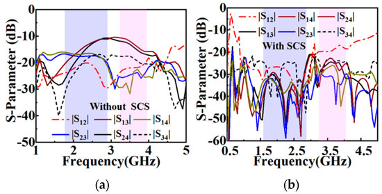
Figure 17.
Simulated isolation port levels with two elements (a) without SCCS and (b) with SCCS.
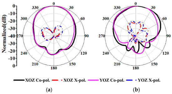
Figure 18.
Radiation patterns of the (a) 4G antenna at 2.2 GHz and (b) 5G antenna at 3.5 GHz.
The MIMO array consists of four 5G antennas and one 4G antenna. The physical diagram of the antenna is shown in Figure 19. It can effectively suppress the offset of the radiation pattern. The spacing between the units is d = 36 mm (0.42 λH). To ensure accurate results, the fabrication prototype of the proposed antenna is also illustrated in Figure 19. Figure 20 shows the S-parameter and realized gain of the 4G antenna and 5G antenna elements in the MIMO array. The impedance bandwidth of the 4G antenna is 1.68–2.75 GHz (|S11| < −15 dB). The realized gain is 8.6 ± 1.3 dBi, and the |S11| of the proposed 4G antenna in the 3.23–4.1 GHz band is lower than −10 dB. The impedance bandwidth of the 5G antenna is 3.25–3.82 GHz (|S33| < −15 dB), and the realized gain is 7.7 ± 0.5 dBi. The results show that the antenna elements still have good radiation and resonance when formed into a MIMO array.
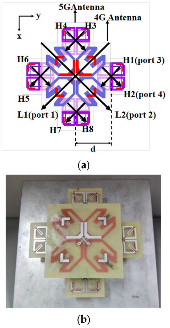
Figure 19.
Configuration and fabrication prototype of the proposed antennas: (a) configuration and (b) prototype.
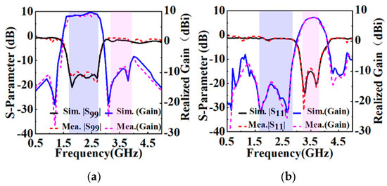
Figure 20.
Simulated and measured S-parameter of the proposed (a) 4G antenna and (b) 5G antenna.
2.4. Mutual Decoupling of 4G/5G Array with Five Elements
The MIMO array consists of four 5G antennas and one 4G antenna. The physical diagram of the antenna is shown in Figure 19. It can effectively suppress the offset of the radiation pattern. The spacing between the units is d = 36 mm (0.42 λH). To ensure accurate results, the fabrication prototype of the proposed antenna is also shown in Figure 19. Figure 20 shows the reflection coefficient and realized gain of the 4G antenna and 5G antenna elements in the MIMO array (the pink/purple shadow show the operation bands of the antennas). The impedance bandwidth of the 4G antenna is 1.68–2.75 GHz (|S11| < −15 dB). The realized gain is 8.6 ± 1.3 dBi, and the |S11| of the proposed 4G antenna in the 3.23–4.1 GHz band is lower than −10 dB. The impedance bandwidth of the 5G antenna is 3.25–3.82 GHz (|S33| < −15 dB). The measured gain is 7.7 ± 0.5 dBi.
Figure 21 and Figure 22 show the difference in the isolation ports between that with and without an SCCS. The results show that the isolation level between the 4G and 5G and the 5G and 5G ports is improved by 15.2 dB and 9.5 dB, respectively. This proves that an SCCS can improve the isolation level of a MIMO array. In addition, neither the 4G or 5G antennas show distinct distortion patterns, as depicted in Figure 23. The HPBW of the MIMO array is 67 ± 5° and 69 ± 5° for the 4G and 5G antennas, respectively.
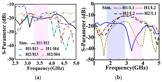
Figure 21.
Simulated isolation port levels of five elements without SCCS between (a) 5G antenna and 5G antenna and (b) 4G antenna and 5G antenna.
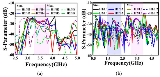
Figure 22.
Simulated and measured S-parameters of the five elements with SCCS between (a) 5G antenna and 5G antenna and (b) 4G antenna and 5G antenna.
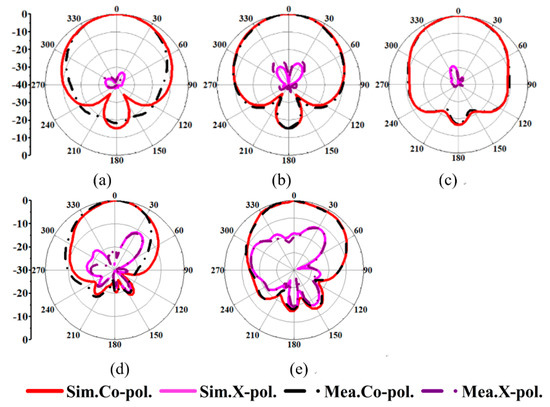
Figure 23.
Simulated and measured radiation patterns of the 4G antenna at (a) 1.7 GHz, (b) 2.2 GHz, and (c) 2.7 GHz; and of the 5G antenna at (d) 3.3 GHz and (e) 3.8 GHz.
3. Conclusions
A short-circuited coupling structure (SCCS) is proposed for the gain-filtering response of base station antennas in this paper. The operation bands of the antennas are 1.7–2.7 GHz (4G) and 3.3–3.8 GHz (5G). In addition, port isolation levels of better than 24 dB between the 5G and 5G antennas and 25.2 dB between the 4G and 5G antennas are also obtained. The measured results validate the stable radiation patterns of each antenna element in both the 4G antenna and 5G antenna. The proposed structure provides a new approach to improve decoupling in 4G/5G MIMO arrays. The simulation and experimental results prove that the structure has good applicability for base station antenna decoupling and filtering response. Thus, this technique can be used in wireless communication devices with microwave/ optical front-ends and other microstructures.
Author Contributions
Methodology, H.S. and B.D.; fabrication and testing, F.Z.; writing—original draft preparation, H.S. and F.Z. All authors have read and agreed to the published version of the manuscript.
Funding
This research received no external funding.
Institutional Review Board Statement
Not applicable.
Informed Consent Statement
Not applicable.
Data Availability Statement
All the data are included in this study.
Conflicts of Interest
The authors declare no conflicts of interest.
References
- Mao, C.-X.; Gao, S.; Wang, Y.; Wang, Z.; Qin, F.; Sanz-Izquierdo, B.; Chu, Q.-X. An Integrated Filtering Antenna Array with High Selectivity and Harmonics Suppression. IEEE Trans. Microw. Theory Tech. 2016, 64, 1798–1805. [Google Scholar] [CrossRef]
- Mao, C.X.; Gao, S.; Wang, Y.; Sanz-Izquierdo, B.; Wang, Z.; Qin, F.; Chu, Q.X.; Li, J.; Wei, G.; Xu, J. Dual-Band Patch Antenna with Filtering Performance and Harmonic Suppression. IEEE Trans. Antennas Propag. 2016, 64, 4074–4077. [Google Scholar] [CrossRef]
- Chen, F.-C.; Hu, H.-T.; Li, R.-S.; Chu, Q.-X. Design of Filtering Microstrip Antenna Array with Reduced Sidelobe Level. IEEE Trans. Antennas Propag. 2017, 65, 903–908. [Google Scholar] [CrossRef]
- Chen, J.-X.; Zhang, Y.-J.; Cai, J.; Li, Y.-L.; Yang, Y.-J. Overall Study of Frequency-Agile Mechanism of Varactor-Loaded λ/4 Resonator for Designing Tunable Filter with Stable Wide Stopband. IEEE Trans. Ind. Electron. 2019, 66, 6302–6310. [Google Scholar] [CrossRef]
- Yang, W.J.; Pan, Y.M.; Hu, P.F. Circularly Polarized Filtering Dielectric Resonator Antenna. In Proceedings of the 2022 IEEE Conference on Antenna Measurements and Applications (CAMA), Guangzhou, China, 14–17 December 2022; pp. 1–3. [Google Scholar]
- Tang, H.; Tong, C.; Chen, J. Differential Dual-Polarized Filtering Dielectric Resonator Antenna. IEEE Trans. Antennas Propag. 2018, 66, 4298–4302. [Google Scholar] [CrossRef]
- Yan, N.; Song, D.; Luo, Y.; Ma, K. A Low-Cost Miniaturized Filtering Dielectric Resonator Antenna Based on SISL for 5G Applications. IEEE Trans. Antennas Propag. 2022, 70, 11344–11352. [Google Scholar] [CrossRef]
- Zhang, Y.; Zhang, Y.; Huang, K.; Liu, S.-J.; Zhang, X.Y.; Liu, Q.H. A Reconfigurable Patch Antenna with Linear and Circular Polarizations Based on Double-Ring-Slot Feeding Structure. IEEE Trans. Antennas Propag. 2022, 70, 11389–11400. [Google Scholar] [CrossRef]
- Li, Y.; Zhao, Z.; Tang, Z.; Yin, Y.; Fed, D. Dual-Band Dual-Polarized Filtering Antenna with High Selectivity for 5G Sub-6 GHz Base Station Applications. IEEE Trans. Antennas Propag. 2020, 68, 3231–3236. [Google Scholar] [CrossRef]
- Zhang, Y.; Zhang, X.-Y.; Liu, Q.-H. Dual-Polarized Filtering Magnetoelectric Dipole Antenna Utilizing Intrinsic Highpass Filter Network and Integrated Lowpass Filter Network. IEEE Trans. Antennas Propag. 2021, 69, 8090–8099. [Google Scholar] [CrossRef]
- Luo, Y.; Zhao, S.; Yan, N.; An, W.; Ma, K.; Meng, F. A Multicompressed-High-Order Modes Dipole Antenna with Wide-Beam and High-Gain Radiations in Two Different Bands. IEEE Antennas Wirel. Propag. Lett. 2023, 22, 1231–1235. [Google Scholar] [CrossRef]
- Wen, L.; Gao, S.; Yang, Q.; Luo, Q.; Yin, Y.; Ren, X. A Compact Monopole Antenna with Filtering Response for WLAN Applications. In Proceedings of the 2019 International Symposium on Antennas and Propagation (ISAP), Xi’an, China, 27–30 October 2019; pp. 1–3. [Google Scholar]
- Chen, C. A Compact Wideband Filtering Omnidirectional Dipole Antenna Without Extra Circuits. IEEE Trans. Antennas Propag. 2022, 70, 1729–1739. [Google Scholar] [CrossRef]
- Liu, N.-W.; Liang, Y.-D.; Zhu, L.; Liu, Z.-X.; Fu, G. A Low-Profile, Wideband, Filtering-Response, Omnidirectional Dielectric Resonator Antenna Without Enlarged Size and Extra Feeding Circuit. IEEE Antennas Wirel. Propag. Lett. 2021, 20, 1120–1124. [Google Scholar] [CrossRef]
- Liu, J.A.; Cao, Y.F.; Zhang, X.Y. A Pattern-Reconfigurable Filtering Patch Antenna Using Embedded Resonators and Switchable Elements. IEEE Trans. Antennas Propag. 2022, 70, 3828–3833. [Google Scholar] [CrossRef]
- Yang, S.J.; Duan, W.; Liu, Y.Y.; Ye, H.; Yang, H.; Zhang, X.Y. Compact Dual-Band Base-Station Antenna Using Filtering Elements. IEEE Trans. Antennas Propag. 2022, 70, 7106–7111. [Google Scholar] [CrossRef]
- Liu, X.; Gao, S.; Hu, W.; Wen, L.; Luo, Q.; Sanz-Izquierdo, B.; Chen, X.; Qian, L.; Sumantyo, J.T.S.; Yang, X.-X. A Compact Dual-Polarized Filtering Antenna with Steep Cut-Off for Base-Station Applications. IEEE Trans. Antennas Propag. 2022, 70, 5941–5946. [Google Scholar] [CrossRef]
- Da Liu, Q.; Dong, Q.; Wen, J.X.; Ye, L.H.; Wu, D.-L.; Zhang, X.Y. Compact Wideband Patch Filtenna with Enhanced Out-of-Band Suppression. IEEE Antennas Wirel. Propag. Lett. 2023, 22, 2310–2314. [Google Scholar] [CrossRef]
- Liu, T.; Jiang, J.; Zhao, L.; Zhao, G.; Zhai, H.; Cai, Y.-M.; Chen, T.; Xu, W. Compact U6G Massive MIMO Antenna Arrays with Double-Layer Partial Reflective Decoupling Layers for Mutual Coupling Suppression. IEEE Open J. Antennas Propag. 2023, 4, 764–778. [Google Scholar] [CrossRef]
- Zhao, G.; Liu, T.; Jiang, J.; Zhao, L.; Huang, G.-L.; Lin, W. Polarization Selective Partial Reflective Decoupling Layers for Mutual Coupling Reduction of Two Closely Spaced Dual-Polarized Antennas. IEEE Trans. Antennas Propag. 2022, 70, 11205–11210. [Google Scholar] [CrossRef]
- He, D.; Yu, Q.; Chen, Y.; Yang, S. Dual-Band Shared-Aperture Base Station Antenna Array with Electromagnetic Transparent Antenna Elements. IEEE Trans. Antennas Propag. 2021, 69, 5596–5606. [Google Scholar] [CrossRef]
- Chang, Y.; Chu, Q.-X. Broadband Dual-Polarized Electromagnetic Transparent Antenna for Cross-Band Scattering Suppression. IEEE Antennas Wirel. Propag. Lett. 2022, 21, 1452–1456. [Google Scholar] [CrossRef]
- Sun, H.-H.; Zhu, H.; Ding, C.; Jones, B.; Guo, Y. Scattering Suppression in a 4G and 5G Base Station Antenna Array Using Spiral Chokes. IEEE Antennas Wirel. Propag. Lett. 2020, 19, 1818–1822. [Google Scholar] [CrossRef]
- Li, Y.; Chu, Q.-X. Self-Decoupled Dual-Band Shared-Aperture Base Station Antenna Array. IEEE Trans. Antennas Propag. 2022, 70, 6024–6029. [Google Scholar] [CrossRef]
Disclaimer/Publisher’s Note: The statements, opinions and data contained in all publications are solely those of the individual author(s) and contributor(s) and not of MDPI and/or the editor(s). MDPI and/or the editor(s) disclaim responsibility for any injury to people or property resulting from any ideas, methods, instructions or products referred to in the content. |
© 2025 by the authors. Licensee MDPI, Basel, Switzerland. This article is an open access article distributed under the terms and conditions of the Creative Commons Attribution (CC BY) license (https://creativecommons.org/licenses/by/4.0/).