Abstract
In this paper, a novel method is demonstrated to sustain vehicle-to-vehicle (V2V) communication on curvy roads via the arrangement of the lateral position of a self-angle-adjustable mirror–reflective road sign (SAAMRS) and light-direction-sensing wide-angle complementary photodiodes (CPDs). Visible light communication (VLC) between vehicles attracts attention as a complementary technology to radio-frequency-based (RF-based) communication technologies due to its wide, license-free spectrum and immunity to interferences. However, V2V VLC may be interrupted on curvy roads due to the limited field of view (FOV) of the receiver or the line of sight (LOS) being interrupted. To solve this problem, an experiment was developed using an SAAMRS along with wide-angle light-direction-sensing CPDs that used a precise peak detection (PPD) method to sustain communication between vehicles in dynamic environments by rerouting the incident light with the highest signal intensity level to the receiver vehicle on curvy roads. We also used real images of curvy roads simulated as polynomials to calculate the necessary rotation angles for the SAAMRS and regions where communication exist. Our experimental results overlapped almost completely with our simulations, with small errors of approximately 4.8% and 4.4% for the SAAMRS angle and communication region, respectively.
1. Introduction
Visible light communication (VLC) is a highly preferred communication technique due to its ability to provide a high bandwidth and resist interference from electromagnetic sources. Since VLC technology communicates using light emitting diodes (LEDs), a revolution in the field of semiconductor lighting has led to the expansion of the usage area of VLC [1]. VLC transfers data by modulating the intensity of visible light, which has a wavelength range of 380 nm to 750 nm [1]. In VLC links, the transmitter circuit sends data by changing the light intensity, and the receiver circuit receives the data by detecting the intensity changes in the incoming light [2]. On the receiver side, a photodiode (PD) detects the incoming light intensity and converts it into current for the receiver circuit to read. In this way, the original data sent by the transmitter become readable [3].
The use of visible light in data transmission provides many advantages. The potential applications of VLC are wide-ranging and offer solutions for many industries, such as wireless internet access in public areas, indoor positioning, smart house lightning systems, and even underwater communications, where radio waves are incapable of propagating [4]. Additionally, VLC provides an energy-efficient and cost-effective solution for data transmission using existing LED-based lighting infrastructure [5]. Also, one advantage of VLC is communication security. VLC works based on the line-of-sight (LOS) principle, which requires light to be transmitted directly over the line [6]; in other words, light propagates through a direct path from the source to the receiver. This means that it is less susceptible to interference and provides more secure communication compared to radio-frequency-based (RF-based) communication systems [7]. As VLC technology advances and its limitations are overcome, it has the potential to revolutionize data transmission by providing safer, faster, and more reliable communication solutions in the near future.
Millions of vehicles are produced and find their way onto roads every year. Unfortunately, traffic accidents increase with an increasing number of vehicles [8]. VLC technology between vehicles has great potential for traffic safety and accident prevention. It is essential for drivers to drive carefully, but being careful is not enough. For this reason, communication methods are being developed between vehicles for safety purposes to reduce the possibility of collisions. VLC between vehicles is one of these methods. Vehicle-to-vehicle (V2V) VLC is used for data communication between vehicles by varying the intensity of light in the headlights and taillights of the vehicles [9]. VLC provides fast and reliable data transfer between vehicles. Thus, smart vehicles can take the necessary precautions where human reflexes are not enough [10].
In V2V VLC, the vehicle in front changes its light intensity to code data using its taillights, and this intensity change in the light is transmitted to the PD and the electronic circuitry located in the headlights of the vehicle behind [11]. Likewise, the vehicle behind changes its light intensity using its headlights, and this change is transferred to the PD in the taillights of the vehicle in front. In this way, data are transferred between the two vehicles. Data encoded by varying the light intensity are transmitted quickly and reliably, even at high speeds. This communication method can be easily implemented by enabling the use of existing headlights and taillights [12,13], requiring no additional equipment and reducing the cost.
In most studies of VLC systems between vehicles, it is generally assumed that vehicles follow each other in perfect alignment in the same lane [14]. However, this assumption is not valid in practice since in real scenarios, vehicles aiming to communicate through VLC can encounter intersections or change lanes, or other vehicles come between them [15,16]. Such situations make it difficult to maintain continuous and reliable communication with VLC technology since VLC requires a LOS.
A multi-directional VLC system is a promising method for acquiring data from vehicles in different lanes on multi-lane roads. It uses three PDs at the receiver side oriented in different directions [17,18]. Differently oriented PDs can increase the field of view (FOV) of the receiver, which can be beneficial at intersection points. However, if there is an obstacle such as a building at an intersection, this method will no longer help the receiver receive the transmitted light.
There are some challenges in V2V VLC, such as the higher velocities of vehicles, their greater degree of mobility, and the unpredictability of vehicle movements [19,20]. However, rather than speed of communication, the main objective is to have active communication in every situation. An active link between vehicles can be lost due to the misalignment of vehicles. The receiver vehicle has a FOV of the incoming optical signal from the leading vehicle’s rear lights. A compulsory LOS condition is required in order not to lose the active link between the VLC transmitter and receiver. Vehicle misalignment related to curvy roads affects the link connectivity. Simulations show that in curvy road conditions without an obstacle at the curves, the connectivity of the link is affected. In the case of a VLC emitter with a half divergence angle of ±15° and a receiver with a FOV of ±30°, the connectivity is lost at angles above 16.8° [21].
From all the reasons mentioned above, we can conclude that alternative methods need to be developed to overcome barriers and maintain communication on curvy roads and at intersections. Reflective mirror surfaces can be used to overcome these obstacles. Some studies have examined through simulations the optimum number of mirrors to rotate in a mirror array during the transmission of light reflected from the transmitter vehicle to the receiver in communication between vehicles parallel to each other [22]. This approach aims at energy efficiency by combining light emission and eye safety elements. In [23], simulation models are proposed using two types of intelligent reflecting systems based on programmable metasurfaces and mirrors to focus the incident optical power towards an indoor VLC receiver. However, both these models are limited to simulations and focus on energy efficiency for light emissions and eye safety, which are different purposes than our goal in this paper. In addition, such simulation models do not provide a way to determine real-world vehicle positions.
In some studies, experimental non-LOS infrastructure-to-vehicle (I2V) VLC modeling has been undertaken in straight links, using a traffic light as a transmitter and a vehicle as a receiver. In [24], the receiver and transmitter were positioned at different azimuth and elevation angles, and the FOV measurements were made using various lens sets on the receiver. The lenses at the receiver improved the received signal amplitude compared to the no-lens case, allowing for communication to be established at longer distances [24]. In other studies, a bidirectional VLC transmission system has been implemented using real motorcycle LED headlights and rear lights as VLC sources [25]. The system was tested in a realistic outdoor scenario at various distances and with different reciprocal orientations of the transmitter and receiver stages (Flat/Optimal). The work in [25] introduces a general method for taking into account the relative angles between the transmitter and receiver, as well as the effect of a finite FOV [25]. The transmission quality of the link is predicted in terms of the expected Packet Error Rate (PER) as a function of the distance between and position of the vehicles for realistic orientations of the receiver stage once the optimal intensity maps cast by the lamps are known [25]. However, both refs. [24,25] cannot be implemented on curvy roads since they only work for straight links with possible lateral separations between the transmitter and receiver, like multi-lane straight roads, and the receivers are manually adjusted to achieve different FOV scenarios. Our article focuses on different objectives, where the priority is maintaining communication on curvy roads where the LOS is interrupted and dynamically adjusting the receiver in the direction of the incoming light with the highest intensity.
On the other hand, in this paper, we developed an experimental setup which allows communication between vehicles to be sustained in dynamic environments like curvy roads. A real-time camera system is used to detect the vehicles’ exact positions. In addition, a self-angle-adjustable mirror–reflective road sign (SAAMRS) along with a main PD circuit and light-direction-sensing wide-angle complementary photodiodes’ (CPDs) circuitry are used to create a pathway for the light. We developed our real-time shape-based vehicle detection model using the OpenCV Python library to calculate the angle required to rotate the SAAMRS correctly [26]. Once the SAAMRS has aligned itself to reflect the incoming light to the following vehicle, the receiver on the following vehicle can only detect the light to a limited extent because the incoming light is not transmitted in a straight line but rather at an angle relative to the normal of the PD on the receiver [27,28]. The CPDs’ circuitry is accordingly designed to detect light from different angles and use the precise peak detection (PPD) method to sustain communication with the highest signal intensity level on curvy roads. Our proposed approach in this paper is an important step towards automating the mirror angle in V2V VLC, enabling uninterrupted, and hence more efficient, communication in dynamic environments such as curvy roads.
We also incorporated simulations to check the performance of our proposed experimental setup. Our simulations consisted of two parts: extracting the road shape information from the input image of the road, as well as generating road shapes with different polynomial coefficients corresponding to curvy roads to define the maximum VLC range using the SAAMRS. With the help of our simulations, we showed that our model can reliably sustain communication on curvy roads. We successfully computed the required mirror angle to properly reflect the incident light from the transmitting vehicle to the receiving vehicle when the two vehicles are not in the LOS of each other. We also presented the maximum distances of communication between the two vehicles for different road shapes, where our model can continue to sustain communication. The SAAMRS rotation angle as well as the communication region from our experimental setup overlapped almost completely with our simulations, with small errors of approximately 4.8% and 4.4%, respectively.
This paper consists of two main parts: SAAMRS simulations, and a V2V VLC experimental setup in a lab environment. In the first part, simulations were developed using MATLAB to demonstrate that different road geometries are compatible with the turning angle of the SAAMRS to maintain communication between the receiving and transmitting vehicles. In addition, the maximum communication distance between vehicles was evaluated for different curvy road geometries. In the second part, real-time image-processing-based vehicle detection experiment was developed along with wide-angle light-direction-sensing CPDs that use the PPD method. Our developed SAAMRS simulations and receiver circuitry, proposed in this paper, present an innovative approach to sustaining and optimizing V2V VLC when the LOS is interrupted in dynamic environments such as curvy roads.
2. Theoretical Background
Adapting LED-based headlights and taillights to transmit and receive data offers great potential for VLC technology, which is a strong candidate for V2V communication. In V2V VLC, the transmitter circuit sends data by changing the light intensity, and the receiver circuit receives the data by detecting the intensity changes in the incoming light. However, since there is no precise alignment between the vehicles in many practical scenarios, this paper has taken this factor into account, enabling communication between vehicles on curvy roads when the LOS is interrupted.
The transmission techniques commonly used in VLC systems include the User Datagram Protocol (UDP) [29,30], and on/off keying (OOK) [31,32], using an arbitrary waveform generator or universal software radio peripheral (USRP) devices (National Instruments, Austin, TX, USA). In our paper, V2V VLC is achieved using OOK, where an LED is employed as the light source for data transmission, and data are carried when the LED is either on or off. For our experiments, a square wave signal is generated using a waveform generator, and this wave is connected to an LED light source, causing the LED to turn on and off. The illuminated LED represents a data value of 1, while the LED being off represents a data value of 0. Communication is established by sending consecutive 1s and 0s. This transmission method can be utilized for simple and cost-effective data transfer, achieved through the rapid on/off switching of the LED. The data receiver detects the state of the LED and reconstructs the data based on the blinking pattern.
We applied image processing techniques using OpenCV to recognize vehicles and determine their positions relative to each other, as well as to the SAAMRS. OpenCV is a popular open-source library that can be used in various tasks by providing image processing algorithms and functions. In our paper, we used the powerful features provided by OpenCV to detect the angles of the vehicles and determine their locations to calculate the necessary angle arrangements for the SAAMRS. However, the mirror raises the problem that the light that reaches the receiver from its reflective surface comes at an angle. As shown in Figure 1, the angle of incidence changes with respect to the normal of the PD of the receiver as the receiver vehicle’s position and orientation changes. PDs perform best in situations where the light is perpendicularly incident on them because the relative spectral sensitivity of the PDs decreases as the angle of incidence moves away from the normal. To solve this problem, we propose a new method involving four CPDs to detect the direction of the incoming light and orient the position of the receiver with respect to this direction.
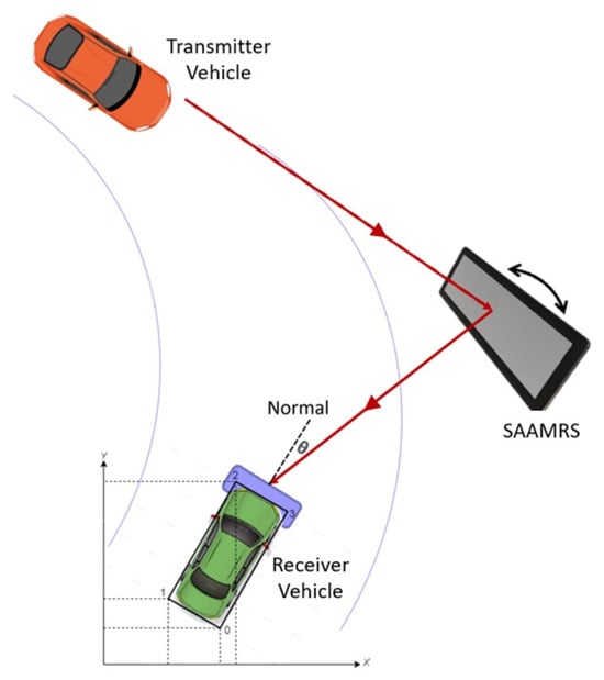
Figure 1.
Self-angle-adjustable mirror–reflective road sign (SAAMRS) and the normal of the receiver.
Quadrant photodiodes (QPs) are used in a variety of applications that require the detection of the direction of incident light [33]. These photodiodes are designed to accurately detect and respond to changes in light intensity and allow the angular displacement to be measured based on which direction the most intense light is coming from [34]. In our work, we chose a different approach to increasing the detection angle, inspired by QPs. To increase the detection angle, we placed four separate CPDs, each facing in a different direction, around a main PD at the center. Each CPD circuit had a PPD circuit on it to detect and hold the incoming signal’s peak voltage values. This configuration allowed us to accurately capture light intensity changes in different directions. Accordingly, our system achieved improved accuracy and sensitivity in creating the best pathway for communication by changing the angle of the receiver towards the highest intensity level of light.
The proportional controller [35,36] software used in the Arduino Uno (Arduino, Turin, Italy) analyzes the data obtained from sensors or other inputs and adjusts the output proportionally. In our experiment, the Arduino Uno was preferred due to its affordable price and accessibility. It can be used effectively in many applications, such as directing, tracking, or controlling light. In our experiment, its interface analyzed the DC voltage information from the different CPDs to determine the direction of light. The voltage values obtained from the CPDs are directly related to the intensity and direction of the light. By comparing the voltage values from these CPDs, the Arduino Uno precisely determines the direction of light and uses this information to rotate the receiver circuitry accordingly. In this way, the proportional controller on the receiver side provides a reliable mean for accurately detecting the direction of incident light.
In our simulations, we approximate curvy roads by fitting a polynomial over them. We fix the position of the SAAMRS to be at the minimum point, the zero-derivative point, of the polynomial. To show that communication is indeed sustainable using our methodology, we plot the lines which represent the light connecting the vehicles to the midpoint of the SAAMRS and define θ as the angle of intersection of those lines, as shown in Figure 2. Since these lines and the mirror lie on the same plane, they must obey Snell’s law of reflection, which equates the angle of incidence to the angle of reflection, given as θ/2 in Figure 2. By looking at the geometry of Figure 2, the SAAMRS rotation angle can be evaluated using (1),
where m1 is the slope of the line joining the transmitter vehicle and the center of the mirror, as shown in Figure 2.
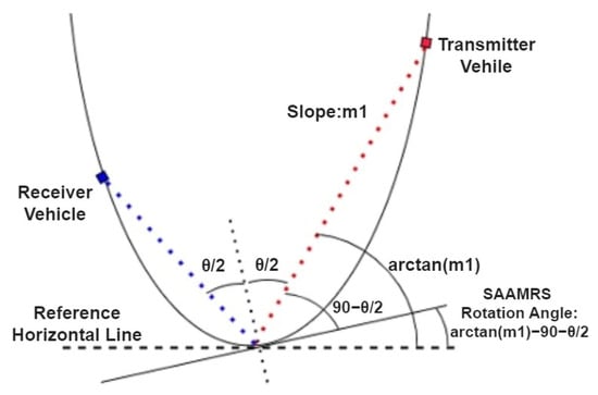
Figure 2.
Theoretical formula of SAAMRS angle.
3. Experimental Setup and Simulations
The main purpose of our simulations and experiments, using SAAMRS and light-direction-sensing wide-angle CPDs, is to create a path for the transmitted light data to reach the receiver with the highest intensity level by adapting the receiver’s direction accordingly.
3.1. Experimental Setup
Figure 3 shows a schematic of the overall experimental setup. The transmitter side consists of a waveform generator producing 10 KHz square wave signals used to drive a LED. A webcam of a laptop is placed in such a way as to capture both the transmitter and receiver sides (vehicles) of the experiment. The webcam is used for real-time object tracking and sends the locations of the vehicles with respect to the mirror to the Arduino Uno. Accordingly, the Arduino Uno rotates the angle of the mirror so that the incident light is directed towards the receiver. The receiver has been optimized to capture the light falling on the PD more effectively by automatically orienting itself in the direction of the most intense light. In this way, the position of the vehicles according to the SAAMRS is determined to adjust the angle of the SAAMRS to reflect the incoming light of the highest intensity from the transmitter vehicle to the receiver vehicle.
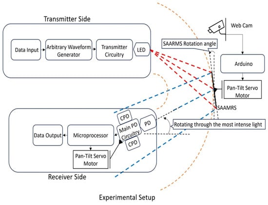
Figure 3.
Schematic of the experimental setup.
3.1.1. Transmitter
In our experimental setup, we made the transmitter design simple, as our focus in this paper is mainly on the SAAMRS and the receiver’s ability to detect the direction of light. The transmitter side, as shown in Figure 3, has a simple structure consisting of a waveform generator that produces 10 kHz square wave signals, where only alternating bit patterns are given as data to drive the LED. The communication modulation technique used for these square wave signals is OOK. Intervehicle communication is achieved using OOK, where data are carried when the LED is either on or off, controlled by the high and low levels of the square wave signals. This method enables the communication system to provide a modulated light signal at a certain frequency and amplitude and realize data transfer modulation.
3.1.2. SAAMRS
Figure 4 shows the experimental setup for the SAAMRS. This self-angle-adjustable mirror provides continuous communication by reflecting the light from the vehicle in front to the vehicle behind. As shown in the overall experimental setup in Figure 3, a webcam of a laptop is placed in such a way as to capture both the transmitter and receiver sides (vehicles) of the experiment. Objects are detected in real time through image processing of the images obtained from the webcam. Using image processing techniques, the positions of the objects relative to the mirror are determined, and the rotation angle of the mirror is calculated using (1) to reflect the light from the transmitter towards the receiver. This calculation is transmitted to the Arduino Uno to rotate the mirror using a pan-tilt servo motor.
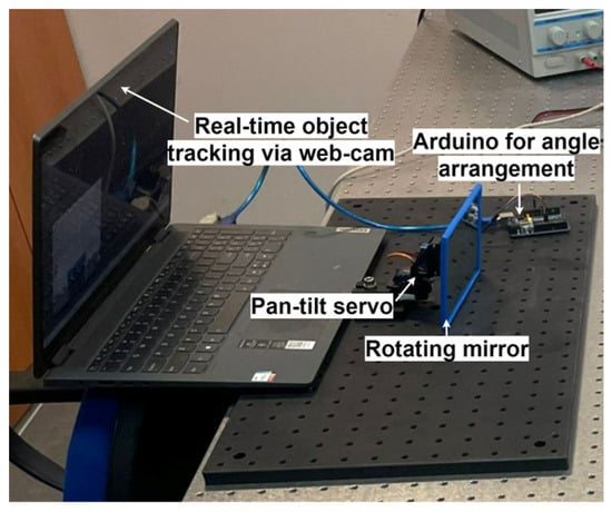
Figure 4.
Experimental setup for the SAAMRS.
Image Processing Algorithm for Rotating the SAAMRS
We identified two objects as car-1 (transmitter) and car-2 (receiver), as shown in Figure 5, which is an image from the webcam. The vehicles are recognized using a special image processing technique that we developed in Python, which includes the TensorFlow library for the training of images for the classification of models to recognize the vehicles and the OpenCV library for real-time image processing. With this technique, we create rectangular contours around the vehicles and select the contour edges on the front sides of the vehicles and set their exact midpoints as the reference points for the vehicles. Using these reference points, we count the pixels on the acquired image using our image processing technique to calculate the distance and angle information on the vehicles in reference to the mirror. Using (1), the necessary angle to rotate the mirror is calculated, and the mirror is rotated accordingly.
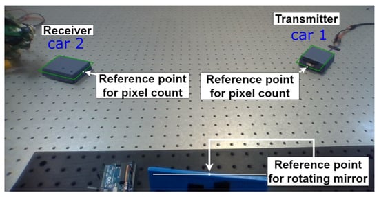
Figure 5.
Webcam view for detection of vehicles.
Firmata’s serial protocol was used for communication between the laptop and the Arduino Uno. The Jupyter Notebook program was used for data training, the PyCharm interface was used for image processing, and the Arduino Uno’s Integrated Development Environment (IDE) was used for the Arduino Uno’s serial communication protocol. Python facilitates image recognition and determination of the objects’ pixel areas, contours, coordinates, and angles.
We used the web-based, open-source Jupyter Notebook program for image classification and data training. With 100 photographs taken from different angles of the blue boxes (car-1 and car-2) appearing in Figure 5, a data set of car-1 and car-2 was created with the help of the Keras library, which is a deep learning library and runs on the TensorFlow library. In order for deep learning to work better, the blue boxes were labeled using the image annotation tool “LabelImg”, and everything other than the object in the images was eliminated. Then, while developing the learning model, 75% of the images in the data sets were used for training, and 25% were used to verify the training. In the training model, we used the SSD MobileNet v2 320x320 detection model due to its real-time object detection capability while maintaining high accuracy [37], which is available in the TensorFlow model zoo repository on GitHub and can detect the location of multiple objects simultaneously. After the training process, the contour detection property of the OpenCV library was used to detect and store the x and y coordinate points of the borders of the cars. With the help of OpenCV, the distance of the objects (blue boxes) relative to the mirror was determined.
Figure 6 illustrates the contours and the x and y coordinate values of a car. The short edges of objects closer to the SAAMRS were selected. The midpoints of these edges were taken as a reference in calculating the slope and angle information.
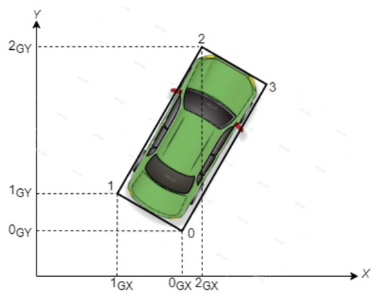
Figure 6.
Contours of the vehicle.
To find the short edge of an object, when the web camera initially captures the contours of an object, we assign corner point “0” to the lower-right corner point with coordinates (0GX, 0GY) and “1” to the lower-left corner point with coordinates (1GX, 1GY), and so on. We can see from Figure 6 that corner points “0”, “1”, and “2” have coordinate values of (0GX, 0GY), (1GX, 1GY), and (2GX, 2GY), respectively. We used these three edge corners for the two adjacent perpendicular sides, [01] and [12], in (2) to determine the shorter side. If (2) given below is satisfied, that means that edge [01] is shorter than edge [12]. If not, then the shorter edge would be [12].
After finding the short side, thanks to NumPy, a mathematics library that allows us to perform scientific calculations, we obtain the angle, slope, and arctan information in (1) and calculate the SAAMRS rotation angle accordingly.
3.1.3. Receiver
The receiver circuit consists of a main PD and four CPDs. Differently oriented CPDs in the proposed receiver circuit are designed to detect light from different angles, as can be seen in the visual representation in Figure 7. The four CPDs are held in place around a main PD that reads the incoming data to sense the direction of light with the help of a light direction detection algorithm and orient the receiver in that direction to increase the light intensity falling on the main PD. In this way, the proposed receiver circuit offers a structure that can focus on a wider FOV.
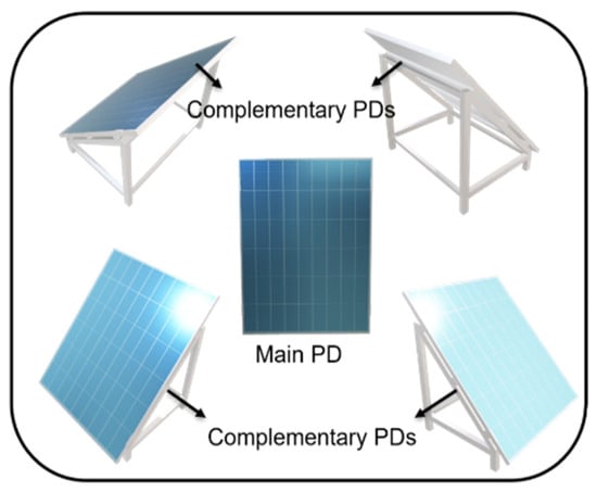
Figure 7.
Positions and orientations of the main photodiode (PD) and four complementary photodiodes (CPDs).
The main PD utilizes expensive components in its circuitry to decode data reaching up to several megahertz. However, the CPDs have cheaper components since they solely focus on detecting the orientation of light, instead of the data speed. A block diagram of the receiver setup is shown in Figure 8.
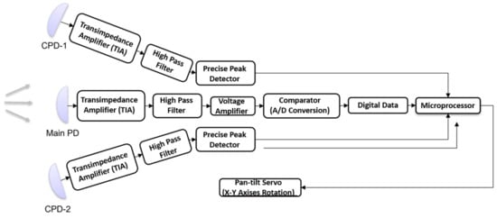
Figure 8.
Block diagram of the receiver.
Main PD Circuit
The main PD circuit shown in Figure 9 is the basic component that performs the data acquisition function. The transimpedance amplifier (TIA), U1, amplifies the weak current signal from the main PD and converts it into a voltage signal. The second order Sallen–Key high-pass filter, U2, suppresses low-frequency noise and filters out unwanted background signals. The voltage amplifier, U3, increases the signal to a higher voltage, resulting in a stronger signal. Finally, the comparator circuit, U4, compares the obtained signal with a certain threshold value and generates an output signal. We used Texas Instruments’ OPA656 op-amps for U1, U2, and U3 in the main PD circuit. The gain–bandwidth product (GBP) of an OPA656 op-amp is 230 MHz, and the circuit elements are chosen to allow up to a 4 MHz bandwidth with a 100 dB gain in the main PD. The combination of these components ensures efficient operation of the main PD circuit and accurate processing of light signals.
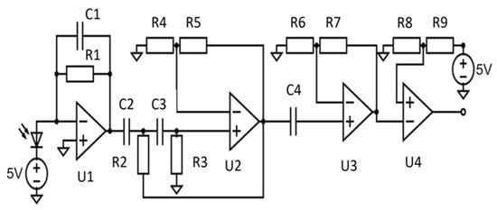
Figure 9.
Main PD circuit.
CPD Circuit
Figure 10 shows the schematic for the CPD part of the receiver. We used a PPD circuit with a TIA, a high-pass filter, and a voltage amplifier in the CPD circuit. The circuit elements U1, U2, and U3 in the CPD circuit in Figure 10 work on the same principle as in the main PD circuit and were explained in the main PD circuit section.
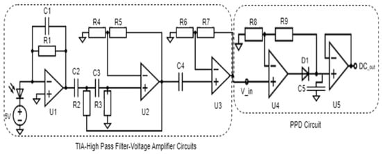
Figure 10.
CPD schematic.
A PPD circuit is an electronic circuit used to detect and hold the peak value in an AC input signal, reporting it as a DC value. In this paper, as shown in Figure 10, the PPD circuit takes a square wave signal from U3 as input and detects the peak of the signal. Once the peak is determined, this value is maintained using a storage element, a capacitor, and the output becomes a DC voltage value.
The DC values from the four CPDs are fed to the analog inputs of the Arduino Uno to be constantly monitored and compared using the light detection algorithm with proportional controller logic. In this way, the receiver is rotated in the direction of the most intense light using the pan-tilt servo motors connected to the Arduino Uno. This method is used to accurately detect the direction of light and properly align the receiver.
In the experiment conducted in our laboratory environment, there is no optical system used in front of the PD in the CPD circuit. When the pan-tilt servo motors are activated, they are positioned at 0° as a default calibration. The reason for using a high-pass filter is to eliminate unwanted signals from the 100 Hz signal caused by background fluorescence light in our laboratory environment.
In the PPD circuit part of the CPD circuit, shown in Figure 10, the op-amp’s (U4) output is connected in series with a diode. When the input voltage exceeds the output voltage, the diode starts conducting due to its forward bias, and the capacitor charges up to the input voltage level; otherwise, the capacitor maintains the diode in the reverse bias direction, preventing the capacitor from discharging back. In this case, once the capacitor is charged to the peak voltage of the input signal, it cannot be discharged back through the diode, as the current leakage will be very little due to the reverse biased diode, and also it discharges very slowly through the second op-amp due to its high input impedance, which serves as a buffer. In this way, the maximum values of the square waves coming from the 4 photodiodes are converted into DC values and transmitted to the analog inputs of the Arduino Uno for comparison to rotate the receiver. The AC input signal and converted DC output signal can be seen in Figure 11.
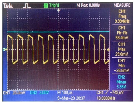
Figure 11.
Output of the voltage amplifier, V_in, shown in yellow, and output of the precise peak detector (PPD) circuit, DC_out, shown in blue.
The reason that the output signal of the voltage amplifier does not appear as a complete square waveform in Figure 11 is because when a square wave is applied to the high-pass filter, the output waveform starts to take a sawtooth form with respect to its frequency.
Light Detection Algorithm
The light detection algorithm uses the Arduino Uno to receive the signals from the output of the CPDs, read these signals via the analogRead function, and map these readings to rotate the pan-tilt servo proportionally via the map function in the Arduino Uno’s IDE. According to the proportional controller’s code (in C++ language) written in the Arduino Uno’s IDE, if the signal coming from the output of the CPD on the positive x-axis is higher than the signal from the CPD on the negative x-axis, the receiver rotates towards the positive x-axis until the signals from both CPDs are almost equal to each other. The same applies to the y-axis. Accordingly, the receiver rotates on the x and y axes via a 2-axis pan-tilt servo motor in the direction of the most intense light. The reason for leaving a margin of error is to reduce vibrations in the rotation of the receiver due to the spurious stray noise in the output DC values of the CPD circuits.
3.1.4. Overall Receiver Circuitry and Experimental Setup
The receiver circuit is shown in Figure 12 side by side with the image from Figure 7 to make the orientations of the CPDs and the main PD more understandable. On the receiver side, car-2, we placed 4 CPDs around the main PD and connected them to the Arduino Uno. Osram SFH203P radial silicon pin PDs are used for the main PD and all the CPDs. The SFH203P PD, which has a wide spectral response and detection range, provides easy integration into various applications with its small size and durable structure. The light direction detection algorithm in the Arduino Uno is used to analyze the input data and detect the incoming light direction with the highest intensity to rotate the designed receiver accordingly. The main PD circuit is connected to the oscilloscope to observe the received signal. The overall setup of our experiment can be seen in Figure 13.
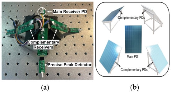
Figure 12.
Receiver circuitry as a (a) real picture and (b) a drawing to show orientations of CPDs and main PD.
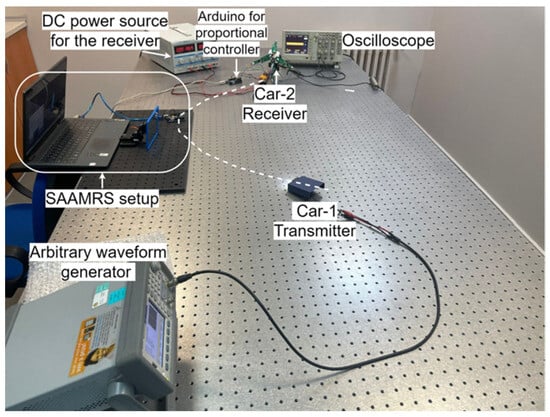
Figure 13.
Overall experimental setup.
3.2. Simulations
In our simulations, we approximate curvy roads by fitting a polynomial over them. Since we are interested in a single turn point, there is a unique minimum within the interval we are interested in. We fix the position of the SAAMRS to be at this minimum point, the zero-derivative point, of the polynomial. A reliable algorithm was developed and tested for several road geometries using MATLAB. This algorithm is used to derive the SAAMRS angle relative to the zero-degree reference horizontal line, as shown in Figure 2, and given in (1), which is required to maintain communication.
Figure 14 shows a simulated road scenario. It can be seen that (1) works in the simulation carried out in MATLAB of two vehicles that are not in the LOS of each other. In this simulation, it is assumed that there are no obstacles to the transmission of light in the area within the inner curve of the road.
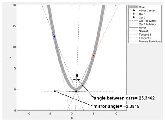
Figure 14.
Simulated road scenario.
We can also see that our theoretical formula given in (1) works on different polynomial paths when there are no obstacles within the outer curve side of the road, as shown in Figure 15.
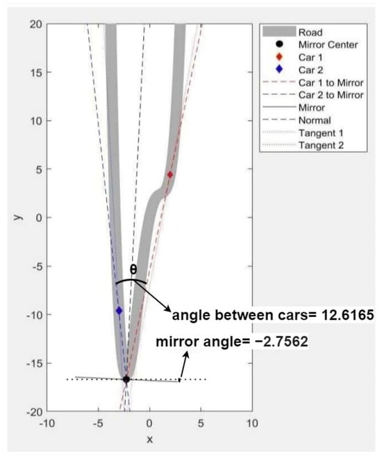
Figure 15.
Simulated road scenario for another path.
Following the completion of our mirror angle calculations, it was decided to extract road information from real road images to enhance the functionality of the simulation. This approach aimed to improve the accuracy and relevance of the simulation, enabling a more realistic representation of real-world scenarios. By incorporating road information extraction, the simulation would provide valuable insights and facilitate a comprehensive analysis of road conditions, thereby enhancing its practicality and effectiveness.
To separate the path from its periphery, algorithms, along with thresholding methods, are employed, as can be seen in Figure 16. Subsequently, a polynomial is fitted appropriately to accurately represent the shape of the path. This paper presents an important step in establishing the connection between vehicles and defining the path correctly.
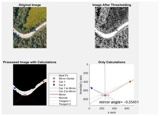
Figure 16.
Road test case 1 for segmentation and polynomial fitting.
Figure 16 and Figure 17 demonstrate the effectiveness of the image processing algorithm in successfully extracting the road from its surroundings. The images clearly demonstrate the effectiveness of the proposed approach in achieving the goal of reliable path separation. With the successful application of the algorithm, the details and boundaries of the path were captured precisely, and an accurate parsing result was obtained. This demonstration highlights the reliability of the algorithm while demonstrating its potential in the development of various road-related applications, such as autonomous driving, road condition analysis, and traffic monitoring.
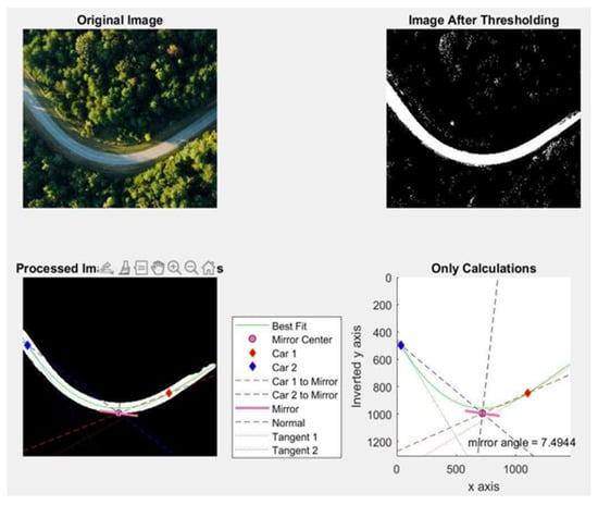
Figure 17.
Road test case 2 for segmentation and polynomial fitting.
In the simulation scenarios so far, we assumed that there were no obstacles inside the curved path that would block the light, and we saw the functionality of (1). In the next stage of the simulations, we simulated a scenario in which there are objects like trees or buildings that block the transmission of light on the inner side of the curved road, as can be seen in Figure 18.
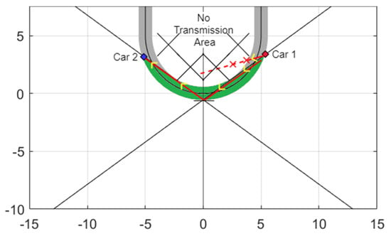
Figure 18.
Simulation with no transmission area.
The main purpose of performing such a simulation is to determine the area, shown in green in Figure 18, where transmission can occur on curvy roads when there are obstacles in the inner area of the curve and to carry out our experiment within this area accordingly.
4. Results
Figure 19 shows the simulation results for our proposed SAAMRS rotation algorithm for different vehicle positions. We have observed that our simulations successfully ran, rotating in the positive and negative directions relative to the x-axis each time, and accurately reflected the light from the vehicle in front to the following vehicle. The correct operation of the algorithm was an important indicator of the effectiveness and reliability of the SAAMRS.
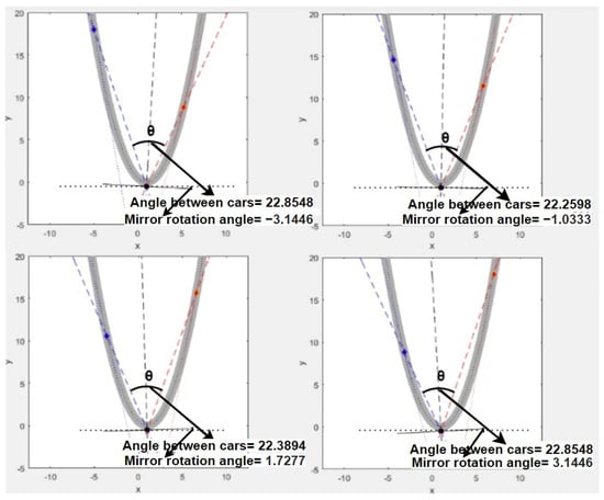
Figure 19.
Simulation results of the SAAMRS for different vehicle positions.
Our simulation results were useful to show that the proposed model is capable of sustaining communication between vehicles at different positions in a random selection of roads. Then, the boundaries of the capability of this model were investigated by conducting further simulations.
Figure 20 shows a processed image of a real curvy road that is approximately 6.6 m wide and 124 m long, along with its 2nd- and 5th-order polynomial fits. In our simulations and experiment, we assume smooth road geometries with a single stationary turning point. In addition, we assume a symmetrical road geometry around this stationary turning point. Also, our communication ranges are limited to tens of meters to reflect realistic scenarios using the limited power of the LEDs from the headlights and taillights of the vehicles. Within this range, and using all of our above assumptions, we saw a very close fit between the 2nd- and 5th-order polynomials, as shown in Figure 20. We show this comparison to demonstrate that the lowest possible degree needed to fit a curve (2nd-order) performs on par with a higher-order fitting (5th-order). Accordingly, to facilitate the demonstration in the experiment, we assumed that the curves of the roads we would encounter in these FOV and LOS limitation problems could be approximated using second-order polynomials with a small loss of accuracy.
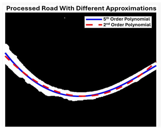
Figure 20.
Comparison of the approximations of 2nd- and 5th-order polynomials.
To systematically analyze the performance of the model, polynomials with a fixed thickness but varying leading coefficients are generated using MATLAB. One basic case is provided in Figure 21. The second-order polynomial with a leading coefficient of 1 is plotted alongside its limiting tangents to reach the minimum point of the road, which is the position of the mirror in our design. The area for which we have sustained communication is colored green.
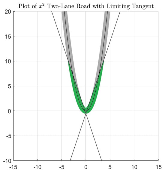
Figure 21.
Sustained communication area demonstration (in green) for the road with a leading coefficient of 1.
The tangents limit the road area such that when a vehicle is lying outside of the green area, that vehicle cannot send a ray of light such that it reaches the center of the mirror. No matter where the other car is placed on the other side of the road after the curve, the vehicles cannot maintain communication.
To quantitatively show the implications of road shape for the maximum distance for active communication, we measured the curve lengths for the upper bound, lower bound, and central line between the farthest point and the zero-derivative point over that arc. Figure 22 shows the upper bound in blue, the central line in green, and the lower bound in red. They are named the outer measure, central measure, and inner measure, respectively.
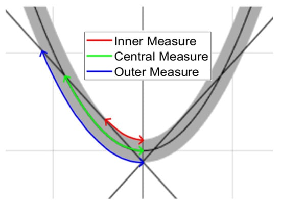
Figure 22.
Measurement technique for maximum distance such that communication is sustainable.
This model is robust against changes in the road width since we measure the relative distance compared to the road width. By analyzing 11 different road models with different leading coefficients, and by measuring the arc distance between the furthest points and the zero-derivative point for sustained communication, we arrive at the results shown in Table 1 and Figure 23. Here, it is assumed that we are dealing with roads with two lanes which are 6.6 m in width in line with the average standards for highways [38]. To have a more readable plot in Figure 23, the leading coefficient values plotted on the x-axis are given on a logarithmic scale.

Table 1.
Data for maximum distance for communication on different two-lane roads.
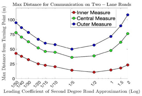
Figure 23.
Maximum distance plots for communication on two-lane roads in road geometries with different leading coefficients.
As Figure 23 shows, our model, by design, has different limitations for different types of roads, depending on the degree of curvature. In fact, this relation is not a monotonous one; we first experience a decrease in the communication distance, followed by an increase as the leading coefficient increases. Accordingly, Figure 24 and Figure 25 with leading coefficients of 1.5 and 0.025, respectively, have longer maximum distances for continuous communication compared to Figure 20 with a leading coefficient of 1.
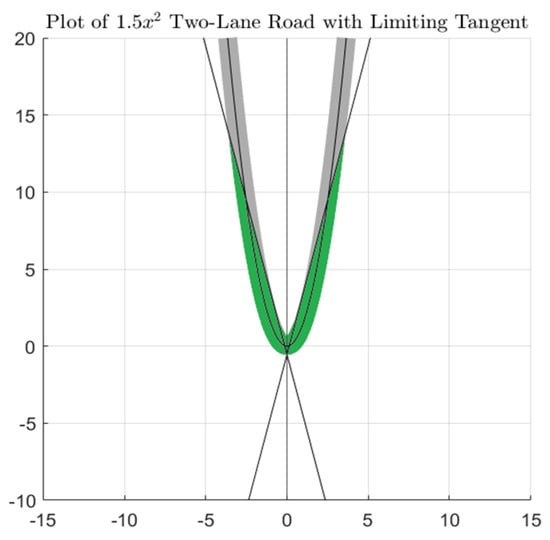
Figure 24.
Sustained communication area shaded green for the road with a leading coefficient of 1.5.
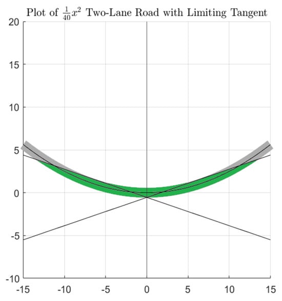
Figure 25.
Sustained communication area shaded green for the road with a leading coefficient of 0.025.
With the help of simulations, we get an idea of the functionality of our model and its applicability to different curvy roads in real life, and we can quantitatively demonstrate the performance range on curvy roads of different shapes.
After completing our simulations, we tested our laboratory experimental setup shown in Figure 13. We observed that the SAAMRS rotates properly to direct the incident light to the receiver. After the light reached the receiver circuit, we observed that the receiver we designed correctly perceived the angle of incidence of the light. In addition, the CPDs used on the receiver side increased the sensing efficiency of the main PD by increasing the light intensity falling on the receiver circuit. These CPDs are specially designed to focus on the direction of the most intense light and rotate the receiver in that direction accordingly.
In our experiment, all of the PDs were rotated approximately 29° in the direction of the most intense light. The results we obtained in the experiment showed that the main photodiode received an approximately 17% increase in light intensity with this method. This increase shows the successful performance of our designed receiver circuitry, allowing the light falling on the receiver to be directed effectively, hence sustaining efficient communication and improving the overall performance of the VLC system.
Among the various parabolic paths that we simulated, we randomly chose 0.2 as our leading coefficient of the polynomial, as highlighted in Table 1, and created an environment proportionally equal to this coefficient value under laboratory conditions. Figure 26 shows our simulation of a road geometry with a leading coefficient of 0.2 and fixed vehicle positions. In our experiment shown in Figure 28, the receiver and transmitter circuits were positioned in proportional locations and with a road geometry similar to our simulation in Figure 26.
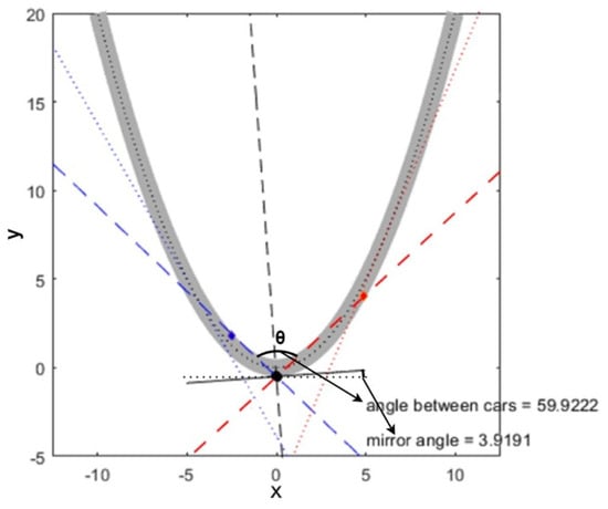
Figure 26.
Chosen vehicle positions from the simulation with a leading coefficient of 0.2 for the polynomial used for the test setup.
Figure 27 shows our geometrically designed lab experiment with a road geometry similar to Figure 26. We blocked the inner side of the road, representing barriers, using a piece of cloth to prevent light from escaping the main road. Figure 27a,b show our main road geometry with the inner road-blocking cloth path with active and inactive VLC, respectively, as the position of the transmitting vehicle is changed. In this sense, we imitated a similar scaled road geometry with our experimental setup to the one we simulated in Figure 26.
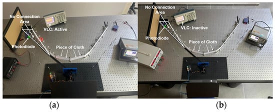
Figure 27.
Our geometrically designed lab experiment with road geometry similar to Figure 26: (a) receiver within communication area, (b) receiver outside communication area.
Figure 28 shows our experimental setup with the main PD only. The red dotted lines show the initial path of the transmitted light and the most intense received light before the SAAMRS is rotated. Since light requires a LOS, no communication was established when the transmitter directed the light or the SAAMRS reflected the light towards the blocked region, and accordingly, our experimental results gave us the region where communication is sustained. We show the no-connection area in Figure 28 as white triangles. Since a point mirror cannot be used in the real world, it was determined that the real-world equivalent of the mirror used in the experiment was 2 m wide and 50 cm high, in proportion to the width of the two-lane road shown in Figure 26.
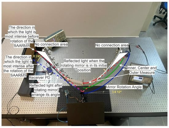
Figure 28.
Test setup of Figure 26 with main PD only.
The four different graphs seen in Figure 19 are images taken from many animated graphs, in which (1) is constantly updated in the “for” loop of the MATLAB codes and the vehicles’ positions are tracked. In Figure 28, we tracked the objects whose relative positions were determined relative to the mirror using the image processing technique, again using Equation (1), and by updating the required mirror rotation angle in a loop in the Python programming language, we ensured that the mirror rotates dynamically according to the vehicles’ positions. Our simulations and experiments were designed to update themselves according to the instantaneous positions of the vehicles, not according to the vehicles’ predetermined positions.
We show in Table 1 the communication region, given as inner measure, outer measure, and central measure values, in which light (on/off light representing “1”s and “0”s of data) was received when simulating the road with a leading coefficient of 0.2. In our experiment, these measurements were calculated by positioning the transmitter and receiver vehicles in different locations to find the limits of the communication region. We compared the simulation and experimental results, and we obtained an SAAMRS rotation angle of 3.9191° from the simulation and 4.12° from the experiment. In addition, from our experiment, we obtained for the communication region 33 cm for the inner measure, 82 cm for the central measure, and 105 cm for the outer measure. These measurements correspond to 13.26 m, 34.44 m, and 44.1 m when scaled to the actual road dimensions in comparison with the highlighted values in Table 1 for a leading coefficient of 0.2. Accordingly, the SAAMRS rotation angle as well as the communication regions from our experimental setup overlapped almost completely with the simulations, with small errors of approximately 4.8% for the rotation angle and 4.4% for the central measure, respectively. Table 2 shows a comparison of the results obtained in the experiment in Figure 28 when scaled to real-life values, along with the simulation results in Figure 26 and the error rates.

Table 2.
Data for comparison of simulation and experiment results for a leading coefficient of 0.2.
There are many sources of errors which account for the error percentages, shown in Table 2, between our simulation results and experimental results. One of the main sources of these errors is the small difference between our simulated and experimental road geometries, mirror location, and vehicle positions. In this paper, we tried to create our experimental setup by imitating a similar scaled road geometry to our simulation, shown in Figure 26, with a leading coefficient of 0.2. However, one of the factors affecting all of our measurements’ accuracy is that we used pixel counting from the image in the simulation to establish the curvy road, as well as to locate our mirror and place the vehicles in our experiment. In fact, we used seven reference points on the right and left sides of the symmetrical path in the simulation to create the scaled version of these points in our experiment. Naturally, the road in our experiment was not completely equivalent to or as smooth as the road in the simulation due to the lack of points used, as well as the possible errors in scaling these points and placing them in our experiment using tools of limited accuracy, like rulers. In addition, there was a small deviation of the location of the mirror and vehicles between the simulation and the experiment, which were placed manually in our experiment. Accordingly, between our simulation and experimental results, we received an error of 4.8% for the rotation angle of the SAAMRS and errors of 7.3%, 4.4%, and 11.9% for the inner measure, central measure, and outer measure, respectively. By adding an extra gear to the pan-tilt system used in this article, we reached an angle resolution of 0.1 degrees in the rotation of the mirror. However, in the experiment, we found an angle of 4.12 degrees, which shows that we made a minimal error in the initial positioning of the mirror, and this had an effect on the error rate for the rotation angle. In order for the road with a coefficient of 0.2 in our experiment to overlap better with the road in our simulation, taking more reference points from the simulation in preparing the road in the experiment would accordingly reduce the errors in the measurements. In addition, with the use of stepper motors, which have a better angular resolution than our used servo motor, the angular rotation of the SAAMRS could be made even more precise, and the error rate could be reduced.
5. Discussion
In this paper, we developed an SAAMRS system that could adjust its angle to ensure the continuity of V2V VLC on curvy roads and showed how far communication can be provided on these roads. The information needed to adjust the angle of the mirror was the distance information relative to the mirrors of two vehicles that were not within each other’s LOS on a curvy road. Using this method, which has never been applied before in the literature, image processing techniques were used, and the positions of the vehicles relative to the mirror were obtained. We found the angle formula required for the SAAMRS to rotate and explained it in (1), as well as in Figure 2. Considering that the light reflected from the SAAMRS to the receiver will not fall perpendicular to the normal of the receiver’s photodiode, using the PPD method, we provided a new approach in the literature to adjusting the receiver angle in the direction of the most intense light. Accordingly, we designed an innovative receiver that senses the direction of the incoming light to improve the quality of communication.
In addition to these designs, we simulated the curved roads we encounter in real life with their polynomial representations. In our simulations and experiment, we considered the inner walls of the curvy roads as barriers and assumed that these barriers did not transmit light, as shown in Figure 28. Considering the fact that there may be barrier-free roads in real life, the maximum communication distances presented in Table 1 can be increased, but we did not find this necessary in this study, and this option can be evaluated in future studies if deemed necessary. The experiments and simulations in this paper are designed so that the vehicles and the SAAMRS are located on the same horizontal plane, where the SAAMRS moves on a single axis. If the vehicles are at different elevations from each other, we must add a second axis to the angular movements of the SAAMRS and modify our design accordingly.
In this paper, as can be seen in Table 1, the maximum communication distances that can be established using our SAAMRS on curvy roads are a few tens of meters. Based on the assumption that vehicles will not enter curved roads at very high speeds, with exceptions, and considering the fact that the average time required for servo motors to rotate 60° is 0.15 s, we can say that the speed of the vehicles will not affect our results.
As can be seen in Figure 20, we took a real-life curvy road image, approximately 6.6 m wide and 124 m long, and fitted two polynomials, 2nd- and 5th-degree, to it. The main reason for this was to show the real-life equivalents of the roads simulated as polynomials. The suitability of the 2nd-order polynomial for the real-life curvy road image supported the polynomial approach we assumed in our experiment and simulations. Also, real-life road scenarios may have one, three, or more lanes. However, in our study, we took two-lane roads as the basis and calculated the maximum distance information in Table 1 and the maximum distance plots in Figure 23 accordingly. In Figure 23, we observed that as the leading coefficient increases for second-degree polynomials, there is first a decrease and then an increase in the communication distance. While setting up our simulations, we based them on roads with a single turning point. Our study can be a guide for roads with more than one turning point by placing an SAAMRS at the zero-derivative point of each turn.
We mentioned in the introduction that there are studies in the literature on wide-angle receivers for vehicles that are not within each other’s LOS. One of these studies is the multi-directional V2V VLC system mentioned in [17], which was used to increase the receiver’s FOV on three-lane roads. According to the results of [17], the communication efficiency is enhanced when manually adjusting the receiver’s FOV by changing the receiver’s photodiode type according to the distance between the transmitter and receiver. The results of our study revealed the effectiveness of a receiver design that is more practical and easier to adapt to real life, eliminating the need to manually change the FOV of the receiver by directing the receiver in the direction of the most intense light. Our receiver turned itself 29° towards the most intense light and achieved a 17% increase in the received light intensity. In addition, when the three-lane road in [17] increases to four lanes, the FOV angles of the receivers need to be adjusted, and the azimuth angles between the receivers facing in different directions need to be manually adjusted again. Our receiver design works with the same efficiency and aligns automatically with the direction of the highest-intensity light even if the number of road lanes increases.
In [18], which is similar in some respects to [17], vehicle-mounted VLC with receiver spatial and angular diversity is studied. Unlike [17], the receivers in [18] are positioned not at a specific point of the vehicle but at the right front, left front, and middle parts of the vehicle. Even though the FOV is increased in this article, it does not seem possible to sustain the active VLC link that an SAAMRS can provide on curvy roads. As the curvature of the curvy road increases, the simulation model in this article loses its functionality, and the communication distance for receivers facing in different directions may be very limited without a complimentary solution such as an SAAMRS. In addition, refs. [17,18] are limited to simulations. We have successfully presented in this paper both an experimental setup as well as a simulation model capable of sustaining an active V2V VLC link on curvy roads of optimum quality, receiving light of the highest intensity. When we scaled the real-life road dimensions, we saw the success of our experimental SAAMRS model, giving 13.26 m for the internal measure, 34.44 m for the central measure, and 44.1 m for the outer measure with a leading coefficient of 0.2 for the approximated 2nd-order polynomial. The active communication region from our experimental setup overlapped almost completely with our simulations, with a small error of approximately 4.4% for the central measure.
There are papers using similar mechanisms to our SAAMRS reflecting the light coming from the receiver to the transmitter at a right angle [22,23], but they are limited to simulations on straight roads. In these papers, we see that these studies were carried out considering eye safety and energy efficiency by using mirror arrays placed on the side of straight roads, but these studies do not have a feature to determine the positions of the vehicles, as in our study, and they were not carried out with the intention of focusing on the continuity of the VLC link. The SAAMRS rotation angle in our experimental setup overlapped almost completely with our simulations, with a small error of approximately 4.8%. The SAAMRS and the receiver system we designed for the uninterrupted continuity of VLC are important milestones that will shed light on future work on V2V VLC technology.
According to the results of [24], as the distance between the receiver and transmitter changes, it is necessary to change lenses for an optimal FOV or even not use lenses at very close distances. The no-lens configuration features the lowest received amplitude values due to the lack of optical gain, and no signal was detected by a 30 m distance. In [24], the lenses are static, and different data sets are collected by manually changing the position and direction of the lenses and receiver. In our paper, four wide-angle CPDs around the main PD determine the direction of the incoming light and rotate the main PD in that direction, making the FOV of a stable receiver dynamic and increases the FOV considerably. However, in future studies, lens sets like the ones used in [24] can be adopted for our designed receiver in real-life scenarios to improve the amplitude of the received signal, allowing light to be captured at longer distances.
On curvy roads, especially when vehicles cannot see each other directly, the continuity of V2V VLC using an SAAMRS may be important in practical applications. Using an SAAMRS, vehicles can exchange real-time data with each other, such as information on location, speed, sudden braking, lane change, and the sudden entry of a third vehicle into a lane to prevent collisions. Additionally, two vehicles can provide each other with information about road conditions and hazards, increasing situational awareness and supporting autonomous driving systems. As a result, the SAAMRS and the receiver design presented in our paper are important elements to increase safety and efficiency on winding roads where V2V VLC is limited by direct LOS restrictions.
6. Conclusions
In this paper, we presented an innovative approach to sustaining and optimizing V2V VLC when the LOS is interrupted in dynamic environments such as curvy roads. We succeeded in directing the highest-intensity light coming from the transmitter vehicle to the receiver vehicle accurately and precisely using our developed SAAMRS and light-direction-sensing wide-angle CPDs to ensure the continuity of VLC between vehicles that are not in each other’s FOV or when the LOS is interrupted on curvy roads. We detected the vehicle positions using a shape-based vehicle location detection algorithm, and communication was sustained on curvy roads accordingly. In this context, we determined the maximum distance limits of communication by simulating curvy roads with various parabolic shapes and successfully carried out our experiments within these limits in a laboratory environment.
We designed a receiver circuit including the circuitry of four CPDs that were held in place around a main PD circuit. The main PD circuit received the light signals and converted these signals into digital data for data analysis and processing. The CPDs’ circuitry determined the direction in which the light was most intense and turned the receiver in that direction accordingly. With this method, we achieved an approximately 17% increase in the received light intensity by rotating the receiver approximately 29° in the direction of the most intense light.
We also carried out simulations and compared the rotation angle and communication region results with our experiment for a curvy road that was approximated as a second-order polynomial with a leading coefficient of 0.2. The SAAMRS rotation angle, as well as the communication region from our experimental setup, overlapped almost completely with the simulations, with small errors of approximately 4.8% for the rotation angle and 4.4% for the central measure, respectively.
We conclusively confirmed that the receiver circuit we designed and the image processing software we developed worked successfully. In the developed experiments and simulations, we achieved success by separately observing the SAAMRS’s ability to reflect light to the receiver vehicle without interruption, the maximum extent to which light could be reflected in paths with various polynomials, and the designed receiver circuit accurately detecting the angle of incidence of the light and reorienting itself towards the highest incoming light intensity accordingly. Our results allowed us to confirm that the developed SAAMRS and receivers performed as expected and ensured continuity in VLC between the vehicles.
There are several factors that may be considered in future studies related to this paper. First, assuming real-world situations involving perfectly symmetrical roads can sometimes lead to oversimplification, which can lead to certain limitations. This article can be inspiration for studies being undertaken on roads with different geometries. Secondly, we used a single light source in our experiment, and this gave us a sufficient proof of concept. Future works can be undertaken to obtain results closer to real-life scenarios by using two light sources, such as in vehicles. In addition, the Python programming language was used in the experiment presented in this article. C is faster than Python because it is a low-level and compiled language; therefore, in future studies, the C programming language may be preferred so that the SAAMRS can respond faster to the vehicle positions. Also, in future studies, the rotation speed and bandwidth limitations of the servo motors that rotate the SAAMRS can be investigated. In this study, we determined, on a simulation basis, the maximum limits within which V2V VLC can occur. In future studies, it can be determined how far the LEDs placed in the rear and front lights of the vehicles can communicate in real life, and accordingly, our maximum distance plots can be revised. Finally, lens sets like the ones used in [24] can be adopted for our designed receiver in real-life scenarios to improve the amplitude of the received signal, allowing light to be captured at longer distances.
Author Contributions
Conceptualization, A.D. and H.Y.; methodology, A.D. and H.Y.; software, A.D. and B.A.; validation, A.D., B.A. and H.Y.; formal analysis, A.D. and H.Y.; investigation, A.D. and H.Y.; resources, A.D., B.A. and H.Y.; data curation, A.D.; writing—original draft preparation, A.D. and B.A.; writing—review and editing, A.D. and H.Y.; visualization, A.D.; supervision, H.Y.; project administration, H.Y.; funding acquisition, H.Y. All authors have read and agreed to the published version of the manuscript.
Funding
This research was funded by Bogazici University Scientific Research Fund (BAP), Istanbul, Turkey, under contract number 19061, and by BAP Research Universities Support Program (ADP), which is supported by the Turkish Council of Higher Education (YÖK) under contract number 50005 (23AYOKADP1).
Institutional Review Board Statement
Not applicable.
Informed Consent Statement
Not applicable.
Data Availability Statement
Data is contained within the article.
Acknowledgments
The authors wish to thank in advance the anonymous reviewers for their valuable time in reviewing our paper.
Conflicts of Interest
The authors declare no conflicts of interest.
References
- Khan, L.U. Visible light communication: Applications, architecture, standardization and research challenges. Digit. Commun. Netw. 2017, 3, 78–88. [Google Scholar] [CrossRef]
- Das, S.; Chakraborty, A.; Chakraborty, D.; Moshat, S. PC to PC data transmission using visible light communication. In Proceedings of the 2017 International Conference on Computer Communication and Informatics (ICCCI), Coimbatore, India, 5–7 January 2017. [Google Scholar] [CrossRef]
- Huang, S.C.; Hsu, W.H.; Chao PC, P.; Tsai, C.H. A New Active 3D Optical Proximity Sensor Array and its Readout Circuit. IEEE Sens. J. 2014, 14, 2185–2192. [Google Scholar] [CrossRef]
- Ibhaze, A.E.; Orukpe, P.E.; Edeko, F.O. High Capacity Data Rate System: Review of Visible Light Communications Technology. J. Electron. Sci. Technol. 2020, 18, 100055. [Google Scholar] [CrossRef]
- Sadat, H.; Abaza, M.; Mansour, A.; Alfalou, A. A survey of NOMA for VLC systems: Research challenges and future trends. Sensors 2022, 22, 1395. [Google Scholar] [CrossRef] [PubMed]
- Lourenco, N.; Terra, D.; Kumar, N.; Alves, L.N.; Aguiar, R.L. Visible light communication system for outdoor applications. In Proceedings of the 2012 8th International Symposium on Communication Systems, Networks & Digital Signal Processing (CSNDSP), Poznan, Poland, 18–20 July 2012. [Google Scholar] [CrossRef]
- Shaaban, R.; Faruque, S. Cyber security vulnerabilities for outdoor vehicular visible light communication in Secure Platoon Network: Review, Power Distribution, and signal to noise ratio analysis. Phys. Commun. 2020, 40, 101094. [Google Scholar] [CrossRef]
- Smeed, R.J. Some statistical aspects of Road Safety Research. J. R. Stat. Soc. Ser. A (Gen.) 1949, 112, 1. [Google Scholar] [CrossRef]
- Kim, Y.H.; Cahyadi, W.A.; Chung, Y.H. Experimental demonstration of VLC-based vehicle-to-vehicle communications under fog conditions. IEEE Photonics J. 2015, 7, 1–9. [Google Scholar] [CrossRef]
- Ionita, S. Autonomous vehicles: From paradigms to Technology. IOP Conf. Ser. Mater. Sci. Eng. 2017, 252, 012098. [Google Scholar] [CrossRef]
- Eldeeb, H.B.; Eso, E.; Jarchlo, E.A.; Zvanovec, S.; Uysal, M.; Ghassemlooy, Z.; Sathian, J. Vehicular VLC: A Ray Tracing Study Based on Measured Radiation Patterns of Commercial Taillights. IEEE Photonics Technol. Lett. 2021, 33, 904–907. [Google Scholar] [CrossRef]
- Uysal, M.; Ghassemlooy, Z.; Bekkali, A.; Kadri, A.; Menouar, H. Visible Light Communication for Vehicular Networking: Performance Study of a V2V System Using a Measured Headlamp Beam Pattern Model. IEEE Veh. Technol. Mag. 2015, 10, 45–53. [Google Scholar] [CrossRef]
- Turan, B.; Narmanlioglu, O.; Ergen, S.C.; Uysal, M. Physical Layer Implementation of Standard Compliant Vehicular VLC. In Proceedings of the 2016 IEEE 84th Vehicular Technology Conference (VTC-Fall), Montreal, QC, Canada, 18–21 September 2016; pp. 1–5. [Google Scholar] [CrossRef]
- Eldeeb, H.B.; Uysal, M. Vehicle-to-vehicle visible light communication: How to select receiver locations for Optimal Performance? In Proceedings of the 2019 11th International Conference on Electrical and Electronics Engineering (ELECO), Bursa, Turkey, 28–30 November 2019. [Google Scholar] [CrossRef]
- Gipps, P.G. A model for the structure of Lane-changing decisions. Transp. Res. Part B Methodol. 1986, 20, 403–414. [Google Scholar] [CrossRef]
- Kala, R.; Warwick, K. Motion planning of Autonomous Vehicles in a non-autonomous vehicle environment without speed lanes. Eng. Appl. Artif. Intell. 2013, 26, 1588–1601. [Google Scholar] [CrossRef]
- Yahia, S.; Meraihi, Y.; Gabis, A.B.; Ramdane-Cherif, A. Multi-directional vehicle-to-vehicle visible light communication with angular diversity technology. In Proceedings of the 2020 2nd International Workshop on Human-Centric Smart Environments for Health and Well-being (IHSH), Boumerdes, Algeria, 9–10 February 2021; pp. 160–164. [Google Scholar]
- Cui, Z.; Yue, P.; Yi, X.; Li, J. Research on Non-Uniform Dynamic Vehicle-Mounted VLC with Receiver Spatial and Angular Diversity. In Proceedings of the ICC 2019—2019 IEEE International Conference on Communications (ICC), Shanghai, China, 20–24 May 2019; pp. 1–7. [Google Scholar] [CrossRef]
- Căilean, A.; Dimian, M. Current Challenges for Visible Light Communications Usage in Vehicle Applications: A Survey. IEEE Commun. Surv. Tutor. 2017, 19, 2681–2703. [Google Scholar] [CrossRef]
- Pathak, P.H.; Feng, X.; Hu, P.; Mohapatra, P. Visible Light Communication, Networking, and Sensing: A Survey, Potential and Challenges. IEEE Commun. Surv. Tutor. 2015, 17, 2047–2077. [Google Scholar] [CrossRef]
- Cuba-Zúñiga, D.J.; Mafra, S.B.; Mejía-Salazar, J.R. Cooperative Full-Duplex V2V-VLC in Rectilinear and Curved Roadway Scenarios. Sensors 2020, 20, 3734. [Google Scholar] [CrossRef] [PubMed]
- Zhan, L.; Zhao, H.; Zhang, W.; Lin, J. An optimal scheme for the number of mirrors in vehicular visible light communication via Mirror Array-based intelligent reflecting surfaces. Photonics 2022, 9, 129. [Google Scholar] [CrossRef]
- Abdelhady, A.M.; Salem, A.K.; Amin, O.; Shihada, B.; Alouini, M.-S. Visible light communications via intelligent reflecting surfaces: Metasurfaces vs. Mirror Arrays. IEEE Open J. Commun. Soc. 2021, 2, 1–20. [Google Scholar] [CrossRef]
- Seminara, M.; Nawaz, T.; Caputo, S.; Mucchi, L.; Catani, J. Characterization of field of view in visible light communication systems for Intelligent Transportation Systems. IEEE Photonics J. 2020, 12, 1–16. [Google Scholar] [CrossRef]
- Meucci, M.; Seminara, M.; Nawaz, T.; Caputo, S.; Mucchi, L.; Catani, J. Bidirectional vehicle-to-vehicle communication system based on VLC: Outdoor tests and performance analysis. IEEE Trans. Intell. Transp. Syst. 2022, 23, 11465–11475. [Google Scholar] [CrossRef]
- Gollapudi, S. OpenCV with python. In Learn Computer Vision Using OpenCV; Apress: New York, NY, USA, 2019; pp. 31–50. [Google Scholar] [CrossRef]
- Mmbaga, P.F.; Thompson, J.; Haas, H. Performance analysis of indoor diffuse VLC MIMO channels using angular diversity detectors. J. Light. Technol. 2016, 34, 1254–1266. [Google Scholar] [CrossRef]
- Tabassum, H.; Hossain, E. Coverage and Rate Analysis for Co-Existing RF/VLC Downlink Cellular Networks. IEEE Trans. Wirel. Commun. 2018, 17, 2588–2601. [Google Scholar] [CrossRef]
- Postel, J. User Datagram Protocol. 1980. Available online: https://dl.acm.org/doi/10.17487/RFC0768 (accessed on 13 March 2024).
- Jarchlo, E.A.; Kouhini, S.M.; Doroud, H.; Eso, E.; Gawłowicz, P.; Zhang, M.; Siessegger, B.; Jung, M.; Ghassemlooy, Z.; Caire, G.; et al. Analyzing Interface Bonding Schemes for VLC with Mobility and Shadowing. In Proceedings of the 2020 12th International Symposium on Communication Systems, Networks and Digital Signal Processing (CSNDSP), Porto, Portugal, 20–22 July 2020; pp. 1–5. [Google Scholar] [CrossRef]
- Luo, P.; Ghassemlooy, Z.; Le Minh, H.; Tang, X.; Tsai, H.-M. Undersampled phase shift on-off keying for camera communication. In Proceedings of the 2014 Sixth International Conference on Wireless Communications and Signal Processing (WCSP), Hefei, China, 23–25 October 2014. [Google Scholar] [CrossRef]
- Yeh, C.-H.; Chow, C.-W.; Wei, L.-Y. 1250 Mbit/s OOK Wireless White-Light VLC Transmission Based on Phosphor Laser Diode. IEEE Photonics J. 2019, 11, 7903205. [Google Scholar] [CrossRef]
- Cincotta, S.; He, C.; Neild, A.; Armstrong, J. Indoor visible light positioning: Overcoming the practical limitations of the quadrant angular diversity aperture receiver (QADA) by using the two-stage QADA-plus receiver. Sensors 2019, 19, 956. [Google Scholar] [CrossRef] [PubMed]
- Allersma, M.W.; Gittes, F.; de Castro, M.J.; Stewart, R.J.; Schmidt, C.F. Two-dimensional tracking of NCD motility by back focal plane interferometry. Biophys. J. 1998, 74, 1074–1085. [Google Scholar] [CrossRef] [PubMed]
- Gupta, A.; Yadav, D.; Raj, A.; Pathak, A. Real-time object detection using SSD mobilenet model of machine learning. Int. J. Eng. Comput. Sci. 2023, 12, 25729–25734. [Google Scholar] [CrossRef]
- Saidonr, M.S.; Desa, H.; Rudzuan, M.N. A differential steering control with proportional controller for an Autonomous Mobile Robot. In Proceedings of the 2011 IEEE 7th International Colloquium on Signal Processing and Its Applications, Penang, Malaysia, 4–6 March 2011. [Google Scholar] [CrossRef]
- Zulkifli, S.A.; Hussin, M.N.; Saad, A.S. MATLAB-Arduino as a low cost microcontroller for 3 phase inverter. In Proceedings of the 2014 IEEE Student Conference on Research and Development, Penang, Malaysia, 16–17 December 2014; pp. 1–5. [Google Scholar] [CrossRef]
- Betus, Y. A Comparison of Roadside Design Approaches in Terms of Road Safety to Improve Turkish Roadside Safety Standards. Master’s Thesis, Middle East Technical University, Ankara, Turkey, 2022. Available online: https://open.metu.edu.tr/handle/11511/98105 (accessed on 31 October 2023).
Disclaimer/Publisher’s Note: The statements, opinions and data contained in all publications are solely those of the individual author(s) and contributor(s) and not of MDPI and/or the editor(s). MDPI and/or the editor(s) disclaim responsibility for any injury to people or property resulting from any ideas, methods, instructions or products referred to in the content. |
© 2024 by the authors. Licensee MDPI, Basel, Switzerland. This article is an open access article distributed under the terms and conditions of the Creative Commons Attribution (CC BY) license (https://creativecommons.org/licenses/by/4.0/).