Article

A Novel 4 × 1 MISO-VLC System with FBMC-OQAM Downlink Signals

1
School of Electronic and Information Engineering, Chongqing Three Gorges University, Chongqing 404100, China
2
School of Information Science and Engineering, Jiaxing University, Jiaxing 314001, China
*
Author to whom correspondence should be addressed.
Photonics 2024, 11(5), 415; https://doi.org/10.3390/photonics11050415
Submission received: 5 April 2024 / Revised: 18 April 2024 / Accepted: 28 April 2024 / Published: 30 April 2024
(This article belongs to the Special Issue Visible Light Communications)

Abstract

:
A novel visible-light communication (VLC) system with 4 × 1 multi-input–single-output (MISO) channels is designed. In the system, the filter bank multicarrier (FBMC) and offset quadrature amplitude modulation (OQAM) techniques are used to generate downlink signals. The principles and implementation methods are proposed and analyzed, and the light intensity and received light power distribution of four LED emitters are discussed. The results demonstrate that it not only satisfies the requirements of indoor information access but also provides daily lighting. The used FBMC-OQAM signals exhibit better reception performance than orthogonal frequency division multiplexing (OFDM) signals. The system used has a lower bit error rate (BER) and larger access bandwidth compared to a 1 × 1 single-input–single-output (SISO) system. It has the potential for application advantages in future indoor VLC system applications.

1. Introduction

With the advent of the 5G era, various types of access services are rapidly developing. There is a growing demand for high-speed, low-power consumption, and secure-access systems. Currently, indoor short-range wireless communication technologies include traditional Wi-Fi, Bluetooth, infrared communication, and wireless telephone communication. However, they all have disadvantages, such as slow communication speed, high power consumption, and low security. Visible-light communication (VLC) is an emerging indoor technology that has captured the attention of researchers because of its low cost, high data rates, frequency-free operation, and high security [1,2,3]. It uses LEDs as the light source and the primary device for transmitting data signals, while also serving as indoor lighting. One of the most common problems faced by the VLC application is the limitation of access bandwidth [4].
In recent years, a few researchers have proposed a variety of techniques to enhance the transmission rate and frequency-band utilization in the indoor access system. One of the most common methods is using the multicarrier modulation technique, which divides high-speed data streams into multiple low-speed sub-streams. This method effectively improves spectral efficiency [5,6,7,8]. It has been widely applied in many optical access systems, such as multi-carrier modulation passive optical network systems, optical wireless communication systems, and indoor visible-light communication systems [9,10,11]. However, the traditional multi-carrier modulation technique, such as orthogonal frequency division multiplexing (OFDM), adds a cyclic prefix (CP) to effectively reduce the impact of inter-symbol interference (ISI). Nevertheless, it reduces the data transmission rate and leads to the wastage of spectrum resources [12,13]. In addition, using rectangular functions as filters in OFDM systems results in large and slow-decaying side lobes, which easily cause interference between subcarriers [14]. In [15], we propose and design a RoF system for downlink 4/16/64QAM-OFDM signals. Although this scheme provides a flexible access method, it wastes bandwidth resources and leads to a certain degree of out-of-band leakage. In [16], although the FBMC system based on frequency-domain expansion can solve the problem of spectrum resource waste caused by the OFDM system, its implementation complexity is high. To resolve the above issues, we propose the integration scheme of filter bank multicarrier (FBMC) and offset quadrature amplitude modulation (OQAM) techniques based on a multiphase network in VLC systems to effectively reduce out-of-band leakage and inter-symbol interference. In addition, to further enhance the downlink bandwidth capacity, 4 × 1 multiple-input–single-output (MISO) access channels are introduced.
In this paper, a novel VLC system with 4 × 1 MISO FBMC-OQAM downlink signals is proposed. We analyze the indoor optical intensity and power-distribution characteristics when four LEDs are used as light sources and modulation signal transmitters. Meanwhile, we test the bit-error-rate (BER) performance of traditional OFDM and FBMC-OQAM signals. The results show that FBMC-OQAM signals have better visible-light signal-reception performance than OFDM signals, and the 4 × 1 MISO system used has a larger downlink bandwidth capacity than the 1 × 1 single-input–single-output (SISO) system. Compared to using conventional OFDM access signals, we use FBMC-OQAM downlink signals as access signals. One advantage of using this scheme is that there is less out-of-band leakage in signal transmission, resulting in higher frequency-band utilization of the system. Moreover, using this access signal can resist the negative impact of frequency offset. Based on this research work, we will consider introducing some machine-learning algorithms in artificial intelligence (AI) technology to further improve the transmission and reception performance of FBMC-OQAM access signals in the future.

2. Material and Methods

Figure 1 shows the block diagrams of OFDM and FBMC transceivers, respectively. In the OFDM system, the high-speed data stream is divided into multiple low-speed subcarriers, which are modulated using QAM modulation. The subcarriers are then converted into time-domain signals through inverse fast Fourier transform (IFFT). A CP is added to the time-domain signals to address the ISI issue in data transmission [17,18,19]. The time-domain signals are then converted back into frequency-domain signals through a fast Fourier transform (FFT) for demodulation and recovery of the original data. In the FBMC system, the transmitter modulates the signal through a synthesis filter that utilizes the polyphase network (PPN) for filtering after the IFFT stage, while the receiver processes the signal through an analysis filter (PPN+FFT) [20,21]. The specific implementation steps are shown in Figure 1b.
Compared to OFDM modulation, the advantage of FBMC-OQAM is using prototype filters instead of conventional rectangular filters. The design of the prototype filter is based on the Nyquist sampling theorem [22]. With the increase in the overlap factor, the quality of signal transmission and reception can be improved, but the trade-off is that the complexity of digital signal processing (DSP) also increases. As  K    (overlap factor) is 2, 3, or 4, the frequency tap coefficients of the filter are shown in Table 1.
The frequency-domain expression of the filter is as follows:
H ( f ) = k = ( K 1 ) K 1 H k sin ( π ( f k M K ) M K ) M K sin ( π ( f k M K ) )
When different values of the overlap factor  K  are used, the filter exhibits varying performance characteristics. We compared the frequency-response performance of  K  = 2, 3, and 4, as shown in Figure 2.
We can observe that the sidelobe attenuation of the signal increases as the overlap factor  K  increases. This implies that the out-of-band leakage decreases. When  K  = 4, the sidelobe attenuation is approximately 40 dB, which meets the system requirements. Therefore, in our study, we choose  K  = 4. As illustrated in Figure 3, it is evident that the FBMC signal exhibits significantly less out-of-band leakage in comparison to the OFDM signal.
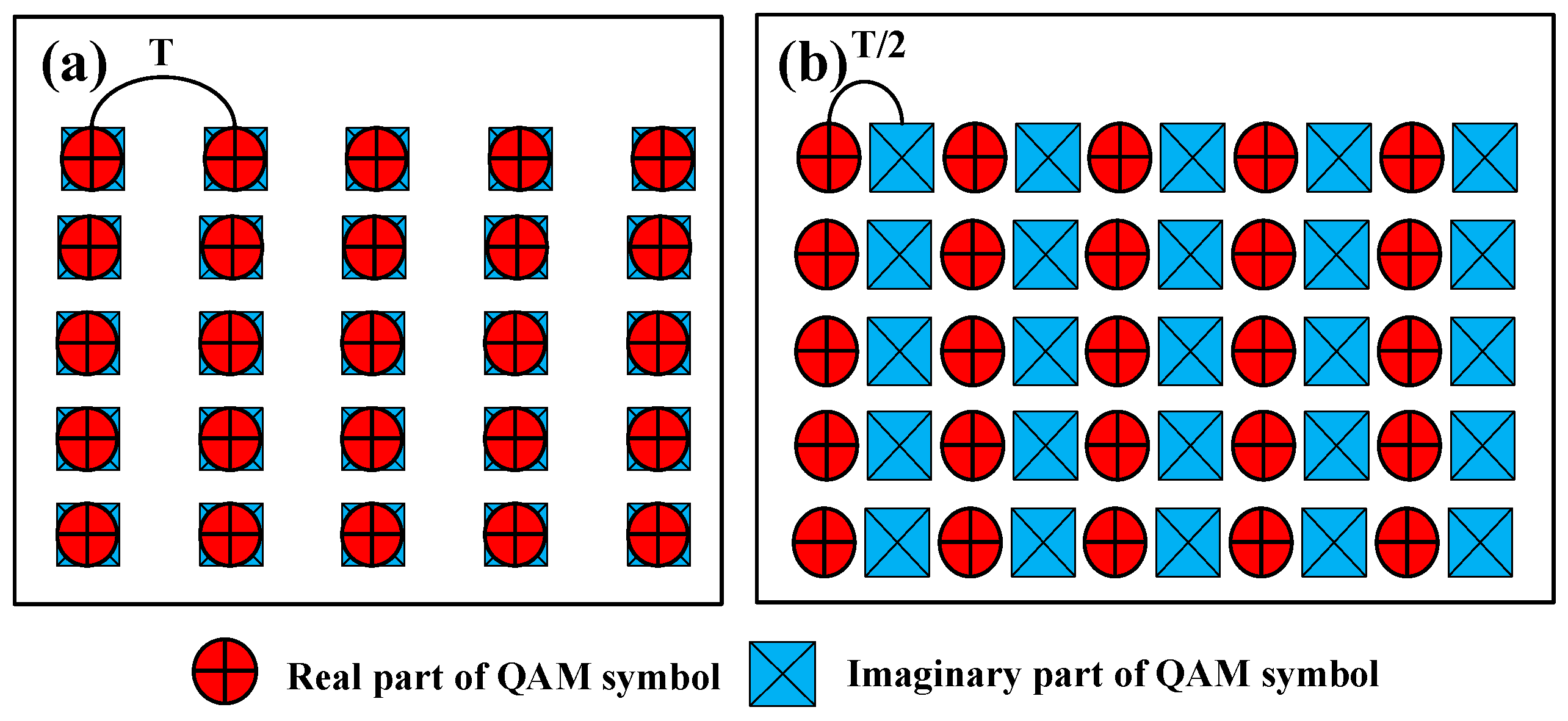
The interference between subcarriers undergoes an orderly transformation between the real and imaginary parts [23,24]. Therefore, we can transmit real part information when there is interference in the imaginary part and transmit imaginary part information when there is interference in the real part. This way, the interference between adjacent subcarriers can be effectively eliminated. Separating the real and imaginary parts can reduce interference but also cut the data transmission rate in half. The OQAM algorithm achieves an increase in symbol rate to twice the original rate by reducing the symbol period T to T/2, thus it does not decrease the bandwidth utilization [25,26]. The time-frequency characteristics of the QAM modulation signals and the OQAM modulation signals are shown in Figure 4.
Algorithm complexity has always been a crucial factor in filter bank design. High computation complexity will result in the occupation of hardware resources and signal transmission time delay. The main problem faced by FBMC is its extensive computational workload. We analyze the implementation complexity below. In OQAM modulation, it is also necessary to first perform QAM modulation of the same order on the data. Subsequently, the data will be divided into two channels, and each  M -point data will be mapped to the virtual space. This operation requires  M  multiplications in the simulation implementation. In the hardware implementation, since the real and imaginary parts of the signal are represented by two channels of data, only a mapping is required. And, no additional operational structure is necessary. However, it results in a doubling of the data volume, which, in turn, doubles the computational load of the subsequent IFFT module and PPN structure. Therefore, the difference in the computational complexity of the two systems can be attributed solely to the FFT module and the PPN structure. The FFT module requires  M   log 2 M /   2  point multiplications and  M   log 2 M  point additions, while the PPN structure requires  K M  multiplications and  K M  additions. The OFDM system only needs  M   log 2 M /   2  point multiplications and  M   log 2 M  point additions. The FBMC/OQAM system requires  M   log 2 M  +  2 K M  point multiplication and  2 M   log 2 M  +  2 K M  point addition. In this system, where  M  = 512 and  K  = 4, OFDM requires 2304 multiplications and 4608 additions. FBMC/OQAM requires 8704 multiplications and 13,312 additions. From the above, it can be seen that the implementation complexity of FBMC/OQAM is much larger than that of OFDM.

3. Results and Discussion

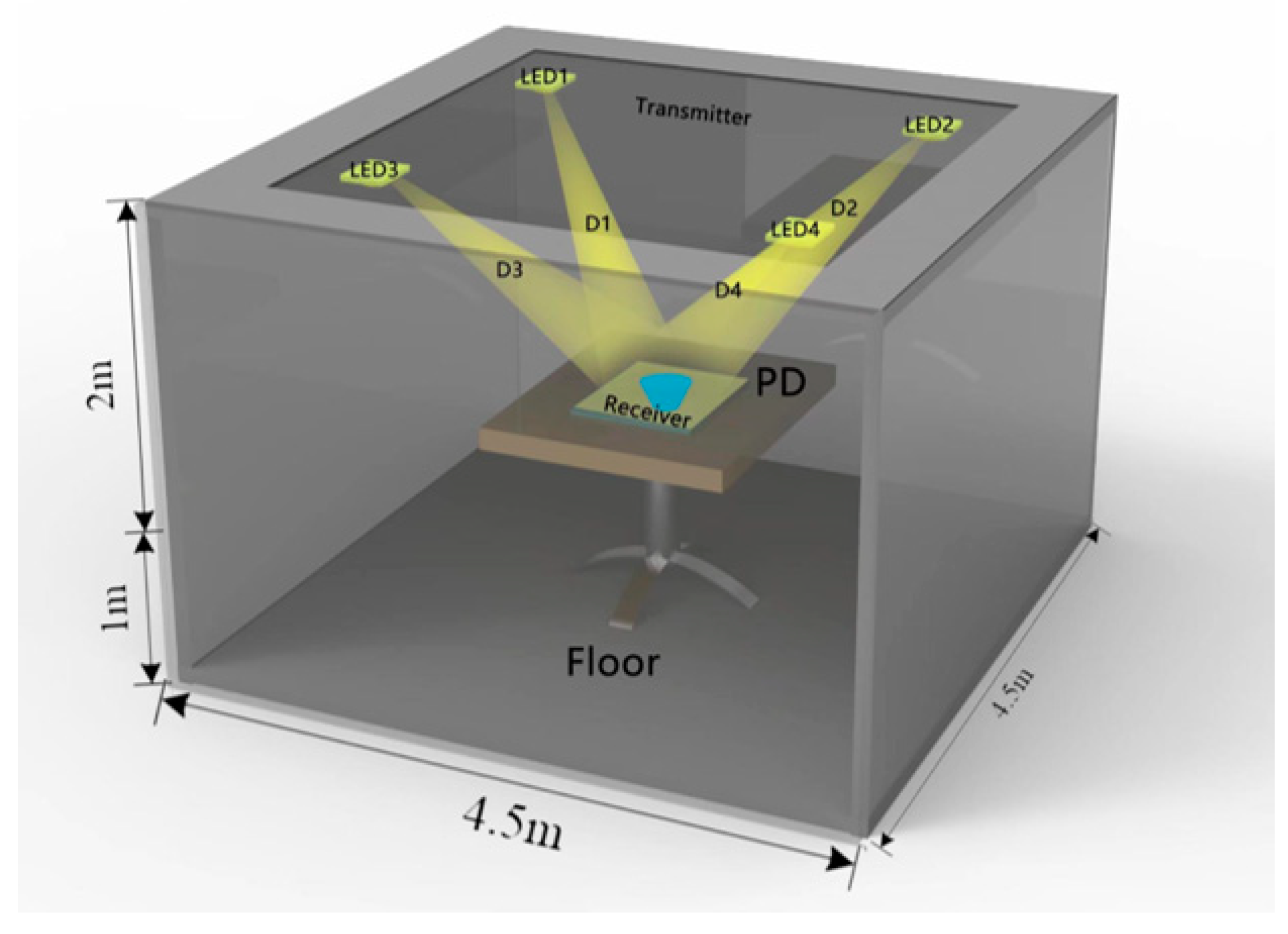
In typical visible-light communication systems, there are two propagation paths between the LED transmitter and the receiver: line of sight (LOS) and non-line of sight (NLOS) [27,28,29]. We focus on studying LOS communication in indoor unobstructed spaces. We propose a four-transmitter–one-receiver VLC system, as shown in Figure 5. The optical transmitter comprises four LEDs, and the modulated signals are transmitted through four line-of-sight paths to a receiver on the desk positioned 1 m above the ground.
The received optical power  p r  at the receiver end can be represented by the following equation:
p r = h ( 0 ) p t
In the above equation,  p t  represents the optical power emitted by the LED light source, and  h ( 0 )  represents the DC gain of the channel. According to the Lambertian radiation model [30], the DC gain of the LOS link is expressed as:
          h 0 = m + 1 A 2 Π D 2 c o s m α T s β g β cos β , 0 < β < F O V 0 ,                                                                               e l s e
where  m  represents the Lambertian radiation coefficient,  D  represents the distance from the white LED light source to the photodetector (PD),  A  is the detection area of the receiver,  α  is the angle between the line connecting the transmitter and the receiver and the vertical direction, β is the incident angle of the PD,  T s ( β )  is the optical filter gain of the receiver, and  g ( β )  is the optical system gain. The simulation parameters are set as shown in Table 2.
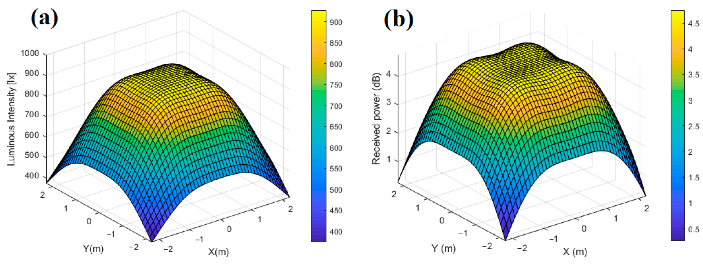
According to Equation (2), the light-intensity distribution of the four LED transmitters is analyzed in the room and the power is received at different locations, as shown in Figure 6. It can be observed that the light intensity and received power are highest near the four groups of LED light sources, and they gradually decrease as the distance from the sources increases. However, from Figure 6a, it can be seen that the minimum value of room illuminance is 373 lx, while the range for general lighting is between 300 lx and 1540 lx [31]. Therefore, using a combination of four groups of white LED arrays is sufficient to meet the daily lighting requirements. Additionally, the distribution of received power, as shown in Figure 6b, indicates that the maximum power is 4.7503 dBm, while the minimum power is 0.2579 dBm. Except for the edges of the room, the SNR in the main activity area is adequate to fulfill the communication requirements.
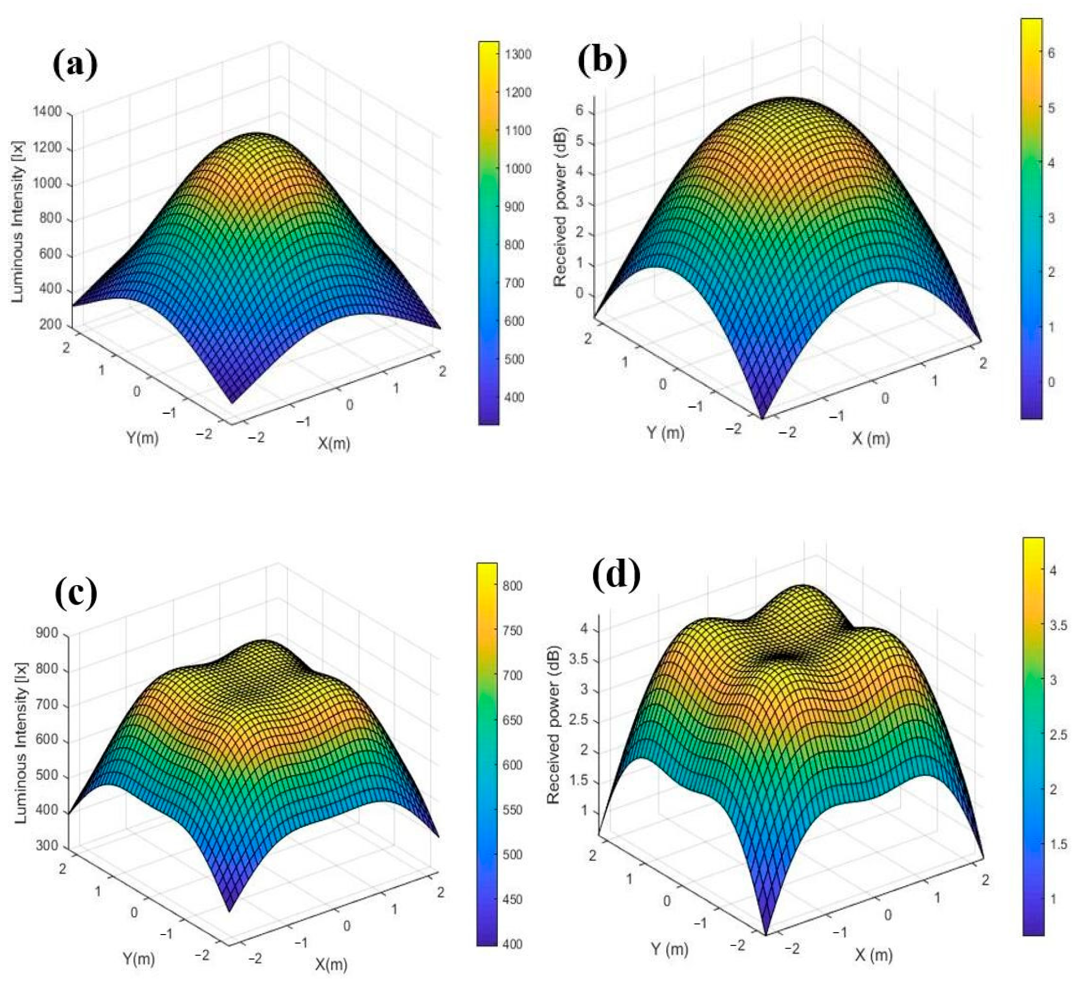
Similarly, we tested at other locations in the room, as shown in Figure 7. When the LED light is positioned close to the center points (−0.75, −0.75, 3), (−0.75, 0.75, 3), (0.75, 0.75, 3), and (0.75, −0.75, 3), the minimum light intensity is 324 lx. Simultaneously, the minimum received optical power is −0.7011 dBm, and the maximum received optical power is 6.6168 dBm. When the LED lamp is positioned near the edge points (−1.25, −1.25, 3), (−1.25, 1.25, 3), (1.25, 1.25, 3), and (1.25, −1.25, 3), the minimum light intensity is 397 lx. The minimum receiving optical power is 0.6518 dBm, and the maximum receiving optical power is 4.2941 dBm.
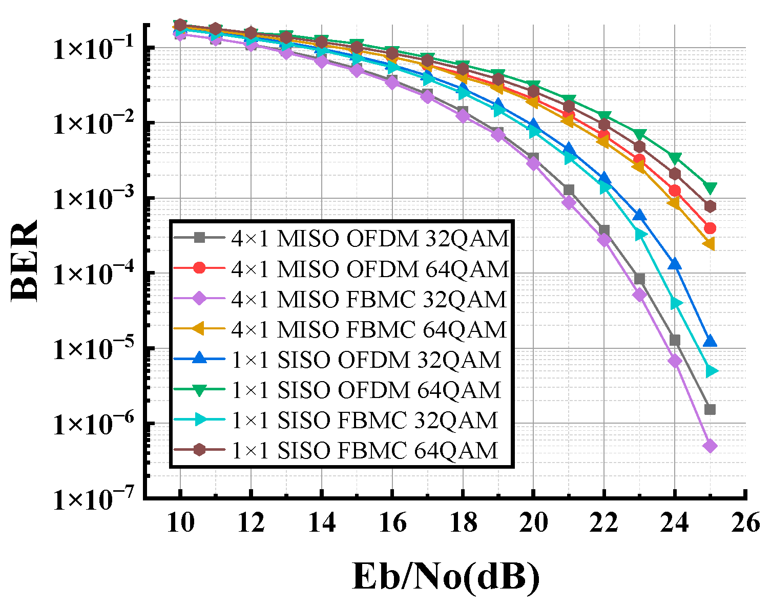
Figure 8 shows the comparison of BER for OFDM and FBMC-OQAM signals in 1 × 1 SISO and 4 × 1 MISO channels. When the SNR is 24 dB, the 4 × 1 MISO FBMC-OQAM (32QAM) achieves the lowest BER (6.74 × 10⁻⁶), while the 4 × 1 MISO OFDM (32QAM) has a slightly higher BER of 1.28 × 10⁻⁵. Similarly, at the SNR of 24 dB with a modulation order of 64, the BER of 4 × 1 MISO FBMC-OQAM is 8.55 × 10⁻⁴, and the BER of 4 × 1 MISO OFDM is 1.24 × 10⁻³. FBMC-OQAM signals demonstrate superior performance in visible-light signal reception compared to OFDM signals. As the SNR is 23 dB and the modulation order is 32, the BER of 4×1 MISO FBMC-OQAM is 5.12 × 10⁻⁵, and the BER of 1 × 1 SISO FBMC-OQAM is 3.28 × 10⁻⁴. Meanwhile, at the SNR of 23 dB, the BER of 4 × 1 MISO OFDM and 1×1 SISO OFDM is 8.31 × 10⁻⁵ and 5.7 × 10⁻⁴, respectively. It can be seen that the 4 × 1 MISO system used has a lower BER and a larger access bandwidth compared to the 1 × 1 SISO system. When the BER is 10−3, the corresponding SNRs for 4 × 1 MISO FBMC-OQAM (32QAM), 4 × 1 MISO OFDM (32QAM), 1 × 1 SISO FBMC-OQAM (32QAM), 1 × 1 SISO OFDM (32QAM), 4 × 1 MISO FBMC-OQAM (64QAM), 4 × 1 MISO OFDM (64QAM), 1 × 1 SISO FBMC-OQAM (64QAM), and 1 × 1 SISO OFDM (64QAM) are 20.86 dB, 21.19 dB, 22.21 dB, 22.50 dB, 23.85 dB, 24.18 dB, 24.72 dB, and 25.31 dB, respectively.
We introduced a frequency offset and compared the signal-reception performance under various frequency offsets. As shown in Figure 9, the BER of the received OFDM signal increases rapidly with the increase in frequency offset. The BER of FBMC increases significantly and gradually. The rapid increase in the BER of OFDM rises rapidly with frequency offset within a specific range and is attributed to the modulation of the system based on FFT transform. The overall anti-frequency offset performance of FBMC is higher than that of OFDM. This is due to the fact that the prototype filter of FBMC is designed to be flat in the band, resulting in low inter-carrier interference. The frequency offset in the subcarrier interval will not cause a significant BER, but it is fundamentally dependent on the modulation method of time-frequency transformation. When the frequency offset exceeds a certain range, the signal-reception performance will deteriorate.
In this scheme, the filter bank is used to achieve the modulation and demodulation of subcarriers. This process enables fast attenuation of out-of-band amplitudes, reduces inter-subcarrier interference and inter-symbol interference, and decreases sensitivity to frequency offset. In addition, FBMC/OQAM can maintain good anti-interference performance in the presence of frequency offset. In OFDM, frequency offset disrupts the orthogonality between subcarriers, introducing interference. MISO can leverage the spatial diversity provided by multiple LEDs to offer diversity gain. This helps mitigate the effects of fading, improving the overall system reliability and performance. Based on the data comparison above, it can be concluded that FBMC-OQAM, combined with MISO technology, offers superior transmission performance. In practical applications, OFDM modulation is chosen due to its low cost, despite its poor reception performance. On the other hand, FBMC/OQAM multi-carrier modulation has a higher cost but provides higher-quality received signals. Therefore, in practical applications, we can choose the appropriate signal modulation types based on specific needs.

4. Conclusions

We have designed a novel VLC system with a 4 × 1 MISO channel, which uses FBMC-OQAM to generate downlink signals. The results show that the FBMC-OQAM signal has better reception performance than the OFDM signal and greatly reduces out-of-band leakage. This system not only multiplies downlink bandwidth capacity but also the used FBMC-OQAM signals offer better reception quality compared with traditional OFDM signals. It has the potential advantages in future indoor VLC system applications.

Author Contributions

Conceptualization, Y.S. and Y.L.; methodology, Y.S., Y.L. and A.W.; validation, Y.Z., C.L. and P.C.; writing—original draft preparation, Y.L.; writing—review and editing, Y.S.; supervision and project administration, R.Z., J.Y. and S.L. All authors have read and agreed to the published version of the manuscript.

Funding

This research was funded by the National Natural Science Foundation of China (61107064), the Science and Technology Research Program of Chongqing Municipal Education Commission (KJZD-M201901201), the Zhejiang Key Research and Development Project (2017C01043), the Chongqing Science and Technology Commission Foundation (cstc2018jcyjAX0038 and cstc2016jcyjA0246), the Chongqing Three Gorges Reservoir Area Geological Environment Monitoring and Disaster Warning Key Laboratory Open Fund Major Project (ZD2020A0104), and the postgraduate scientific research innovation project of Chongqing Three Gorges University (YJSKY22014).

Institutional Review Board Statement

Not applicable.

Informed Consent Statement

Not applicable.

Data Availability Statement

Data underlying the results presented in this paper are not publicly available at this time but may be obtained from the authors upon reasonable request.

Conflicts of Interest

The authors declare no conflicts of interest.

References

  1. Chi, N.; Zhou, Y.; Wei, Y.; Hu, F. Visible light communication in 6G: Advances, challenges, and prospects. IEEE Veh. Technol. Mag. 2020, 15, 93–102. [Google Scholar] [CrossRef]
  2. Gancarz, J.; Elgala, H.; Little, T.D.C. Impact of lighting requirements on VLC systems. IEEE Commun. Mag. 2013, 51, 34–41. [Google Scholar] [CrossRef]
  3. Kashef, M.; Ismail, M.; Abdallah, M.; Qaraqe, K.A.; Serpedin, E. Energy efficient resource allocation for mixed RF/VLC heterogeneous wireless networks. IEEE J. Sel. Areas Commun. 2016, 34, 883–893. [Google Scholar] [CrossRef]
  4. Sadat, H.; Abaza, M.; Mansour, A.; Alfalou, A. A survey of NOMA for VLC systems: Research challenges and future trends. Sensors 2022, 22, 1395. [Google Scholar] [CrossRef]
  5. Lin, H.; Siohan, P. An advanced multi-carrier modulation for future radio systems. In Proceedings of the 2014 IEEE International Conference on Acoustics, Speech and Signal Processing (ICASSP), Florence, Italy, 4–9 May 2014; IEEE: Piscataway, NJ, USA, 2014; pp. 8097–8101. [Google Scholar]
  6. Shaik, N.; Malik, P.K. A comprehensive survey 5G wireless communication systems: Open issues, research challenges, channel estimation, multi carrier modulation and 5G applications. Multimed. Tools Appl. 2021, 80, 28789–28827. [Google Scholar] [CrossRef]
  7. Chen, R.; Park, K.H.; Shen, C.; Ng, T.K.; Ooi, B.S.; Alouini, M.S. Visible light communication using DC-biased optical filter bank multi-carrier modulation. In Proceedings of the IEEE 2018 Global LIFI Congress (GLC), Paris, France, 8–9 February 2018; pp. 1–6. [Google Scholar]
  8. Ibrahim, A.; Prat, J.; Ismail, T. Asymmetrical clipping optical filter bank multi-carrier modulation scheme. Opt. Quantum Electron. 2021, 53, 230. [Google Scholar] [CrossRef]
  9. Khan, J.; Khan, Y.; Ullah, S.; Shafique Querishi, S. Transmission performance and cost analysis of multi-carrier-based wavelength division multiplexed passive optical access network. J. Opt. Commun. 2020, 41, 159–165. [Google Scholar] [CrossRef]
  10. Li, X.; Yu, J. W-band RoF transmission based on optical multi-carrier generation by cascading one directly-modulated DFB laser and one phase modulator. Opt. Commun. 2015, 345, 80–85. [Google Scholar] [CrossRef]
  11. Yang, Y.; Zeng, Z.; Cheng, J.; Guo, C.; Feng, C. A relay-assisted OFDM system for VLC uplink transmission. IEEE Trans. Commun. 2019, 67, 6268–6281. [Google Scholar] [CrossRef]
  12. Tao, Y.; Liu, L.; Liu, S.; Zhang, Z. A survey: Several technologies of non-orthogonal transmission for 5G. China Commun. 2015, 12, 1–15. [Google Scholar] [CrossRef]
  13. Seo, B.; Sim, D.; Lee, T.; Lee, C. Efficient time synchronization method with adaptive resource configuration for FBMC systems. IEEE Trans. Commun. 2020, 68, 5563–5574. [Google Scholar] [CrossRef]
  14. Arjun, R.; Shah, H.; Dhua, S.; Appaiah, K.; Gadre, V.M. Low complexity FBMC for wireless MIMO systems. Phys. Commun. 2021, 47, 101332. [Google Scholar] [CrossRef]
  15. Shao, Y.F.; Chen, L.; Wang, A.R.; Zhao, Y.J.; Long, Y.; Ji, X.P. Analysis of different sub-carrier allocation of M-ary QAM-OFDM downlink in RoF system. Optoelectron. Lett. 2018, 14, 40–43. [Google Scholar] [CrossRef]
  16. Tao, Y. Simulation performance analysis of FBMC-OQAM system based on frequency spreading. In Proceedings of the Second International Conference on Physics, Photonics, and Optical Engineering (ICPPOE 2023), Kunming, China, 10–12 November 2023; SPIE: Bellingham, WA, USA, 2024; Volume 13075, pp. 682–689. [Google Scholar]
  17. Hashimoto, N.; Osawa, N.; Yamazaki, K.; Ibi, S. Channel estimation and equalization for CP-OFDM-based OTFS in fractional doppler channels. In Proceedings of the 2021 IEEE International Conference on Communications Workshops (ICC Workshops), Montreal, QC, Canada, 14–23 June 2021; IEEE: Piscataway, NJ, USA, 2021; pp. 1–7. [Google Scholar]
  18. Liu, Y.; Yi, J.; Wan, X.; Zhang, X.; Ke, H. Evaluation of clutter suppression in CP-OFDM-based passive radar. IEEE Sens. J. 2019, 19, 5572–5586. [Google Scholar] [CrossRef]
  19. Yli-Kaakinen, J.; Loulou, A.; Levanen, T.; Pajukoski, K.; Palin, A.; Renfors, M.; Valkama, M. Frequency-domain signal processing for spectrally-enhanced CP-OFDM waveforms in 5G new radio. IEEE Trans. Wirel. Commun. 2021, 20, 6867–6883. [Google Scholar] [CrossRef]
  20. Nadal, J.; Nour, C.A.; Baghdadi, A. Low-complexity pipelined architecture for FBMC/OQAM transmitter. IEEE Trans. Circuits Syst. II Express Briefs 2015, 63, 19–23. [Google Scholar] [CrossRef]
  21. Rottenberg, F.; Nguyen, T.H.; Gorza, S.P.; Horlin, F.; Louveaux, J. Advanced chromatic dispersion compensation in optical fiber FBMC-OQAM systems. IEEE Photonics J. 2017, 9, 7204710. [Google Scholar] [CrossRef]
  22. Bellanger, M.; Le Ruyet, D.; Roviras, D.; Terré, M.; Nossek, J.; Baltar, L.; Bai, Q.; Waldhauser, D.; Renfors, M.; Ihalainen, T. FBMC physical layer: A primer. PHYDYAS 2010, 25, 7–10. [Google Scholar]
  23. Cui, W.; Qu, D.; Jiang, T.; Farhang-Boroujeny, B. Coded auxiliary pilots for channel estimation in FBMC-OQAM systems. IEEE Trans. Veh. Technol. 2015, 65, 2936–2946. [Google Scholar] [CrossRef]
  24. Cheng, X.; Liu, D.; Wang, C.; Yan, S.; Zhu, Z. Deep learning-based channel estimation and equalization scheme for FBMC/OQAM systems. IEEE Wirel. Commun. Lett. 2019, 8, 881–884. [Google Scholar] [CrossRef]
  25. Laabidi, M.; Zayani, R.; Bouallegue, R. A novel multi-block selective mapping scheme for PAPR reduction in FBMC/OQAM systems. In Proceedings of the 2015 World Congress on Information Technology and Computer Applications (WCITCA), Hammamet, Tunisia, 11–13 June 2015; IEEE: Piscataway, NJ, USA, 2015; pp. 1–5. [Google Scholar]
  26. Nguyen, T.H.; Gorza, S.P.; Louveaux, J.; Horlin, F. Low-complexity blind phase search for filter bank multicarrier offset-QAM optical fiber systems. In Proceedings of the Signal Processing in Photonic Communications, Vancouver, BC, Canada, 18–20 July 2016; Optica Publishing Group: Washington, DC, USA, 2016. SpW2G. 2. [Google Scholar]
  27. Lu, Y.; Dai, L. Near-Field Channel Estimation in Mixed LoS/NLoS Environments for Extremely Large-Scale MIMO Systems. IEEE Trans. Commun. 2023, 71, 3694–3707. [Google Scholar] [CrossRef]
  28. Alkama, D.; Ouamri, M.A.; Alzaidi, M.S.; Shaw, R.N.; Azni, M.; Ghoneim, S.S.M. Downlink performance analysis in MIMO UAV-cellular communication with LOS/NLOS propagation under 3D beamforming. IEEE Access 2022, 10, 6650–6659. [Google Scholar] [CrossRef]
  29. Yang, H.; Wang, Y.; Seow, C.K.; Sun, M.; Si, M.; Huang, L. UWB sensor-based indoor LOS/NLOS localization with support vector machine learning. IEEE Sens. J. 2023, 23, 2988–3004. [Google Scholar] [CrossRef]
  30. Cevik, T.; Yilmaz, S. An overview of visible light communication systems. arXiv 2015, arXiv:1512.03568. [Google Scholar] [CrossRef]
  31. Choi, S.J.; Lee, D.S.; Jo, J.H. Lighting and cooling energy assessment of multi-purpose control strategies for external movable shading devices by using shaded fraction. Energy Build. 2017, 150, 328–338. [Google Scholar] [CrossRef]
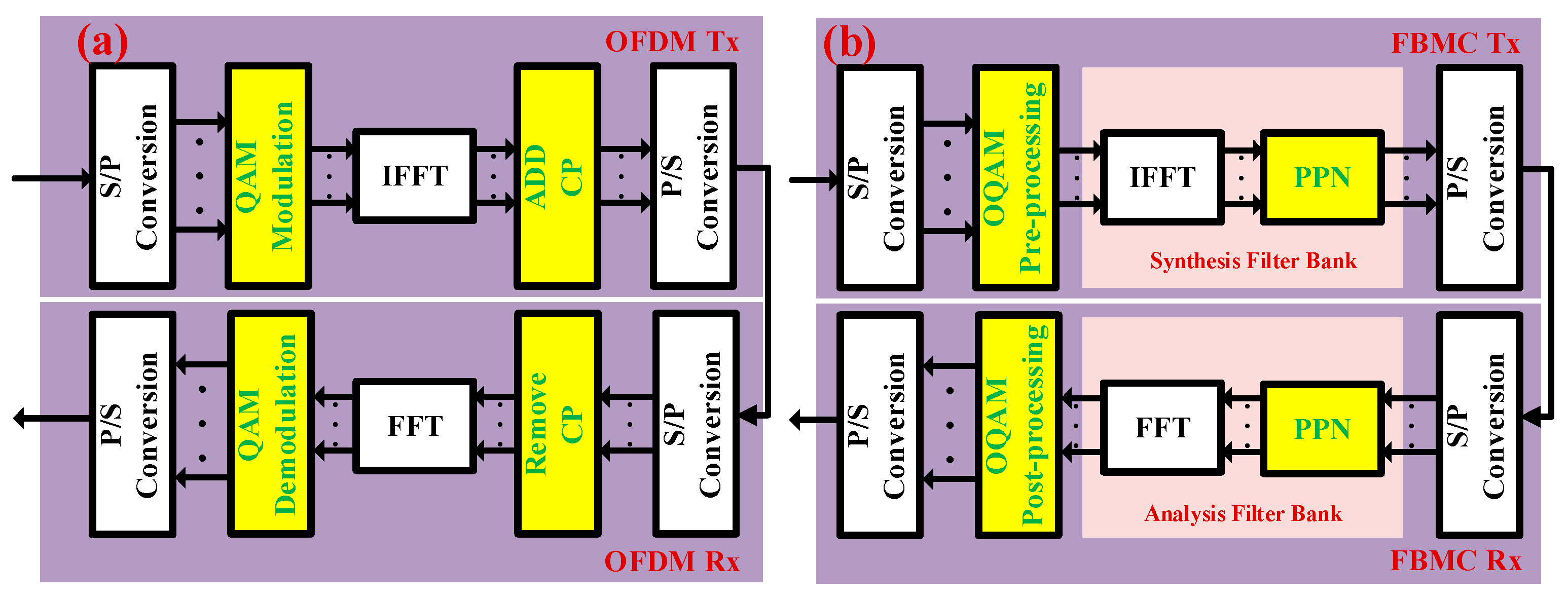
Figure 1. (a) OFDM transmitter and receiver and (b) FBMC-OQAM transmitter and receiver.
Photonics 11 00415 g001
Figure 2. Frequency response of filters with different overlap factors.
Photonics 11 00415 g002
Figure 3. Power spectral density plot of OFDM signal and FBMC signal.
Photonics 11 00415 g003
Figure 4. (a) QAM time-frequency characteristics and (b) OQAM time-frequency characteristics.
Photonics 11 00415 g004
Figure 5. Indoor MISO-VLC system.
Photonics 11 00415 g005
Figure 6. (a) Light-intensity distribution map with four LED arrays. (b) Received power map with four LED arrays.
Photonics 11 00415 g006
Figure 7. (a) Light-intensity distribution map with four LED arrays near the center point, (b) Received power map with four LED arrays near the center point, (c) Light-intensity distribution map with four LED arrays near the edge point, and (d) Received power map with four LED arrays near the edge point.
Photonics 11 00415 g007
Figure 8. BER vs. SNR comparison of OFDM and FBMC-OQAM signals in 1 × 1 SISO and 4 × 1 MISO downlink channels.
Photonics 11 00415 g008
Figure 9. BER vs. SNR comparison of OFDM and FBMC-OQAM signals under different frequency offset conditions.
Photonics 11 00415 g009
Table 1. The tap coefficient of filter with different overlap factor.
K H 0 H 1 H 2 H 3 σ 2 ( d B )
21 2 / 2 //−35
310.9114380.411438/−44
410.971960 2 / 2 0.235147−64
Table 2. Simulation parameters.
ParameterValue
RoomSize4.5 m × 4.5 m × 3 m
Space Position(−1.125, −1.125, 3)
(−1.125, 1.25, 3)
(1.125, 1.125, 3)
(1.125, −1.125, 3)
Optical TransmitterSemi-angle at half power70°
Transmit Power30 mW
LED Array60 × 60
Center Emission Intensity300~900 lx
Optical ReceiverEffective Area1 cm2
FOV70°
Elevation90°
Disclaimer/Publisher’s Note: The statements, opinions and data contained in all publications are solely those of the individual author(s) and contributor(s) and not of MDPI and/or the editor(s). MDPI and/or the editor(s) disclaim responsibility for any injury to people or property resulting from any ideas, methods, instructions or products referred to in the content.