Abstract
Laser speckle has a negative effect on laser projectors, so reducing laser speckle is crucial for the development of laser projector displays. We primarily focus on studying the laser speckle contrast of laser projector displays and the mechanism for reducing speckle. Based on the theory of decreasing temporal and spatial coherence of laser light, this report derives the complete formula for calculating speckle contrast in a laser projector display and provides detailed calculation procedures. According to the comprehensive formula, the primary factors influencing speckle contrast encompass wavelength, spectrum, angles of incidence or observation of lasers, the roughness of the screen surface, the number of independent speckle patterns generated by a moving diffuser, and the number of resolution elements within one eye resolution element in the projector lens. Various methods have been used in the projection engine to suppress speckle, and the main factors for reducing speckle have been verified through theoretical calculations and experimental verification. At a testing distance of 700 mm and with an F-number of 41.7 for the detector lens, the RGB laser speckle contrasts were measured to be 9.1%, 7.3%, and 10.4%, respectively, which aligns well with the results obtained from theoretical calculations. Meanwhile, the speckle contrast of the white field was also measured, yielding a result of 5.6%. The speckle contrast becomes imperceptible when the viewing distance exceeds 2000 mm in our projection system.
1. Introduction
When high-coherence laser light is reflected from a roughened surface, the random roughness of the surfaces contributes to introducing random phase variations [1]. Most surfaces, such as walls or projector screens, are rough on the scale of a visible optical wavelength. Various microscopic facets of the roughened surface emit spherical waves as secondary light sources when laser light is reflected, and laser speckle is observed due to interference between these spherical waves. Speckle contrast is maximum when the roughness of the projector screen surfaces is close to the scale of the optical wavelength, and it will decrease as the surface roughness increases. The presence of laser speckle has a detrimental impact on the performance of laser projectors; thus, mitigating its effects assumes paramount importance in advancing the development of laser projector displays. Many laser speckle reduction methods have been reported, such as broadening the spectrum [2] through high-frequency driving current [3], using a laser module with diverse wavelengths [4], utilizing random lasers [5], and employing polarization diversity [6] or angle diversity [7,8]. Other methods that have been developed include using a moving random diffuser plate [9,10], rotating a diffractive optical element [11] or microlens array [12], and using a motionless changing diffuser [13]. However, previous reports mainly focus on the single factor or method to study the laser speckle. The laser projector system is complicated, and many factors have an impact on the speckle contrast, such as the wavelength, spectrum, angles of incidence or observation of lasers, roughness of the screen surface, number of independent speckle patterns generated by a moving diffuser, and number of resolution elements within one eye resolution element in the projector lens. Then, a comprehensive speckle contrast formula for laser projectors, encompassing the primary factors influencing speckle contrast, is necessary for researching and developing the laser projector system.
With the advancement of visible semiconductor lasers, laser projection displays have gained widespread usage across various applications owing to their enhanced contrast, heightened brightness, and expanded color gamut. In this report, we mainly study the laser speckle contrast of laser projector displays and the mechanism for reducing speckles. Based on the theory of decreasing the temporal coherence and spatial coherence of laser light, we derive the complete formula for calculating the speckle contrast of a laser projector display and provide detailed calculation procedures. According to the complete formula, the main factors that affect speckle contrast are wavelength, spectrum, angles of incidence or observation of lasers, the roughness of the screen surface, the number of independent speckle patterns created by the moving diffuser, and the number of resolution elements within one eye resolution element in the projector lens. The majority of factors that contribute to reducing speckle will be discussed and analyzed. Based on the conclusions drawn from our analysis, we have designed a projection engine to experimentally test and validate our theoretical calculations.
2. Theoretical Analysis
According to the basic theory of speckle formation, the mechanism for reducing speckle mainly depends on decreasing the temporal coherence and spatial coherence of laser light. Regarding speckle suppression through the reduction in temporal coherence [14], the spectrum of laser light affects temporal coherence. Temporal coherence decreases when the spectrum broadens. When the incidence and observation angles are approximately equal, the normalized cross-correlation of two speckle fields and can be shown as follows:
where is the first-order characteristic function of the surface height fluctuations , and represents the translation of the speckle pattern with respect to the observation point when changing the angles of incidence or observation and the expansion or contraction of the speckle pattern by changing the laser wavelength. Then, the speckle contrast is
where is the autocorrelation function of the normalized power spectrum. When the source has a Gaussian-shaped spectrum, the autocorrelation function of the normalized power spectrum is found to be
Assume that the surface height fluctuations are Gaussian; then,
where
Then, the speckle contrast can be shown as Equation (6). More derivation procedures can be found in ref [13].
where is the center frequency of the spectrum; represents the 1/e width of the spectrum; represents the height distribution with standard deviation; is the average wavelength of incidence laser; and and are incidence and observation angle, respectively.
As for the speckle suppression caused by a reduction in spatial coherence, the speckle contrast reduces when two independent and uncorrelated speckle patterns are added. When two independent speckle patterns with the independent intensities and are added, the total detected intensity can be expressed as
The negative exponential probability density functions of two speckle pattern intensities are
The probability density function of the sum of independent speckle patterns implies that
The first and second moments of the sum intensity are given by
According to and , the result is
Then, the speckle contrast is given by
When the average intensity of two speckle patterns is equal, then the minimum speckle contrast by the sum of two independent and uncorrelated speckle patterns will be . The speckle contrast reduces to the expression where N is the sum of the independent speckle pattern with an equal average intensity.
The projection engine consists of a combiner system, an illumination system, and a projection lens. Various methods have been employed in each system to suppress speckle. For instance, the wavelength and spectrum of lasers in the combiner system affect speckle contrast by reducing temporal coherence, as discussed in Equation (6). The factors, such as the moving diffuser and projection lens in the illumination system and projection lens system, will be discussed later. The simple beam path diagram is shown in Figure 1. Both a moving diffuser and a static diffuser are used in the system to suppress speckle. According to the analysis by Goodman [14], when the diffuser does not overfill the projection lens, speckle contrast in the projector system is
where represents the number of statistically independent speckle patterns resulting from the movement of the diffuser, and represents the number of projector lens resolution areas contained with one eye or the detector resolution at the projection screen.
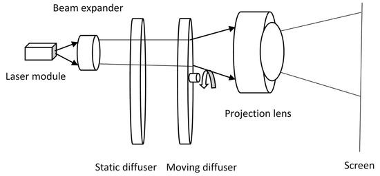
Figure 1.
The diagram illustrates the simple beam path of a laser projection engine.
As the diffuser moves, each point on the diffuser experiences a changing phase of illumination. Consequently, the points on the screen generate a random walk of amplitudes, resulting in the speckle intensity at any point on the screen changing over time. In order to calculate the number of statistically independent speckle patterns, expressed the plane of two diffusers and expressed the screen plane.
where the point spread function of the laser projector system is
The optical field of the static diffuser is
where expresses the plane of two diffusers, is the optical field of the moving diffuser, and are the transmission functions of the moving diffuser and static diffuser, respectively, is the pupil function of the projection system, and are the contributing phase of the moving diffuser and static diffuser, is the linear velocity of the moving diffuser, is the wavelength of incident light, and is the distance between projection lens and screen. Since the imaging system has been assumed to be space invariant, it suffices to calculate these auto-covariance functions at a single pair of image coordinates, which we take to be (x = 0, y = 0).
The temporal autocorrelation function of the screen fields is
where is the linear velocity of the moving diffuser and is the moving time of the diffuser, , , , , , and are the variances of and , and and are the normalized autocorrelation functions of the phases.
The temporal autocorrelation function of the screen fields can be simplified as
The normalized intensity auto-covariance function is
The number of statistically independent speckle patterns depends on the distance of the moving diffuser and the projector lens resolution. According to Goodman [14], the number of statistically independent speckle patterns is
where represents the time of moving the diffuser.
The correlation time of the speckle intensity is
where, for a circular pupil in the imaging system of this report, the factor has a width of approximately ; then, the number of statistically independent speckle patterns is
When is greater than the duration of one rotation of a moving diffuser, then the number of statistically independent speckle patterns is
where represents the linear velocity of the moving diffuser, represents the radius of the moving diffuser, represents the effective diameter of the projection lens, and represents the distance between the projection lens and screen.
As for the resolution elements of the projector lens within one eye resolution element, M depends on the resolution element of the eye and the resolution element of the projector lens on the screen, as shown in Figure 2.
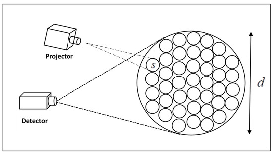
Figure 2.
The large circle of diameter d represents one resolution element of the detector, while the smaller circles of diameter s represent resolution elements of the projector lens.
The large circle of diameter represents one resolution element of the detector on the screen, while the smaller circles of diameter represent the resolution element of the projector lens. The resolution elements of the projector lens within one eye resolution element can be represented as
where the resolution element of the projector lens on the screen can be represented as
The resolution element of the detector on the screen can be represented as
where and represent the distance between the projector lens and the screen and the distance between the detector and the screen, respectively. and represent the effective diameter of both the projection lens and the detector lens. represents the wavelength of incident light.
The speckle contrast in the projector system depends not only on the number of statistically independent speckle patterns and the number of resolution areas within one eye or detector at the projection screen but also on the wavelength, spectrum, and roughness of the screen. The complete formula for calculating speckle contrast in a laser projector display can be presented as
where
The complete formula for calculating speckle contrast in a laser projector display can be presented as
According to the complete formula, the main factors that affect speckle contrast are wavelength, spectrum, angles of incidence or observation of lasers, the roughness of the screen surface, the number of independent speckle patterns created by moving diffuser, and the number of resolution elements within one eye resolution element in the projector lens.
3. Calculation and Experiment
In this report, the projection engine consists of three parts, as shown in Figure 3. The first one is a combiner system, which is used to collect and collimate the lights of the semiconductor RGB (red, green, and blue) laser. The second one is an illumination system, which is designed to control the light out of the fly eye onto the DMD chip, generating particular spot sizes and incident angles. The moving and static diffusers are installed in the illumination system, as shown in Figure 3. The last part is a projection lens, which is used to project the DMD image onto the screen with high resolution and low distortion. Each part has factors that affect the speckle contrast, such as the wavelength, spectrum, and angles of incidence or observation of lasers in the combiner system; the moving diffuser and static diffuser in the illumination system; and the F-number and focal length of the projection lens.
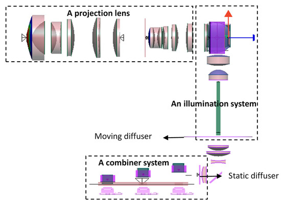
Figure 3.
The diagram of the projection engine consists of three parts: a combiner system, an illumination system, and a projection lens. The red arrow indicates the orientation of the image.
In the projection engine system, the wavelengths of the RGB laser used in a combiner system are 638 nm, 525 nm, and 465 nm, respectively. The FWHMs (full widths at half maximum) of RGB lasers are 7.36 nm, 6.5 nm, and 4.3 nm, respectively. The rotational frequency of the moving diffuser is 120 Hz, and the radius of the moving diffuser is 19.5 mm in the illumination system. The F-number and focal length of the projection lens are 1.7 and 12.5 mm, respectively. The detector is the speckle contrast measurement system from OXIDE. According to the report by Shigeo Kubota [15], the equivalent circular aperture diameter is approximately 1.2 mm, obtained by simulating the human eye in measurements of speckle from laser-based projection displays. Then, the F-number and focal length of the detector lens are 41.7 and 50 mm, respectively. The distance between the projector lens and the screen is 2150 mm, and the distance between the detector and the screen is 700 mm.
According to Equation (31), the speckle contrast decreases as the FWHM of RGB lasers increases, when the other parameters in the projection engine remain unchanged, as shown in Figure 4. The speckle contrast increases as the wavelength red-shifts when the FWHM of RGB lasers are equal. When the laser wavelength is smaller than the screen roughness, the random fluctuations in roughness will lead to random variations in the light phase. Each point on the illuminated rough surface can be considered as a secondary light source, emitting spherical waves into free space. These spherical waves interfere with each other to form speckles. As the laser wavelength approaches closer to the screen roughness, there is an increase in speckle contrast. This explains why there is an increase in speckle contrast as the wavelength red-shifts.
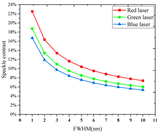
Figure 4.
The speckle contrast decreases as the FWHM of RGB lasers increases.
As for the roughness of the screen, the speckle contrast decreases as the roughness of the screen increases. The principle is that when the screen roughness exceeds the laser wavelength, this random fluctuation of roughness will result in a random fluctuation of the light phase. Each point on the illuminated rough surface can be considered as a secondary light source, emitting spherical waves into free space. These spherical waves interfere with each other to form speckles. The rougher the screen is, the lower the contrast of the formed speckle, as shown in Figure 5.
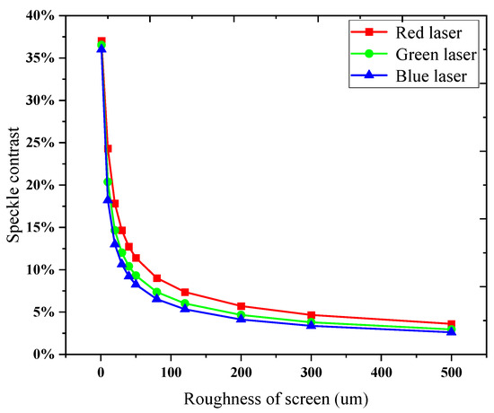
Figure 5.
The speckle contrast decreases as the roughness of screen increases.
The number of independent speckle patterns created by a moving diffuser is critical to the speckle contrast, according to theoretical analysis. As the rotational frequency of the moving diffuse increases, the number of independent speckle patterns also increases. However, the number of statistically independent speckle patterns remains constant when the time required to move the diffuser exceeds one rotation duration, as demonstrated in Equation (24). And when the number reaches a certain amount, as shown in Figure 6, there is no obvious change in the speckle contrast. According to Equation (31), when the value of N reaches a certain threshold, the formula will approach 1/M. At this point, increasing the value of N does not result in any significant change in speckle contrast.
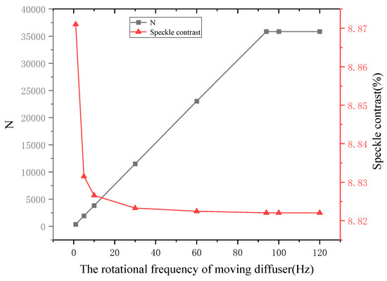
Figure 6.
The number of independent speckle patterns and speckle contrast change as the rotational frequency of the moving diffuse increases.
In the theoretical calculation, Table 1 shows the values of RGB laser speckle contrast and the parameters in the projection engine system. and represent the distance between the projector lens and the screen and the distance between the detector and the screen, respectively. and represent the effective diameter of both the projection lens and the detector lens. According to Equation (31), when the viewing distance is 700 mm, the RGB laser speckle contrast is 9.38%, 7.44%, and 10.48%, respectively.

Table 1.
The value of RGB laser speckle and the parameters.
The value of in the projection system is only 4.6 according to Table 1, which severely affects the speckle contrast. The value of in the projection system depends on various factors, such as the F-number and focal length of the projector lens and detector lens, the distance between the projection lens and screen, and the viewing distance. As the viewing distance increases, the value of in the projection system also increases, resulting in a decrease in RGB laser speckle contrast, as shown in Figure 7. The speckle contrast will decrease to less than 4%, which is imperceptible to humans [16], when the viewing distance exceeds 2000 mm. The F-number of both the projection lens and detector lens also has a significant effect on the value of and the speckle contrast. As the F-number of the projection lens increases, the value of decreases, resulting in an increase in RGB laser speckle contrast, as shown in Figure 8a. Regarding the F-number of the detector lens, the results are the opposite. The speckle contrast decreases as the F-number of the detector lens increases, as shown in Figure 8b.
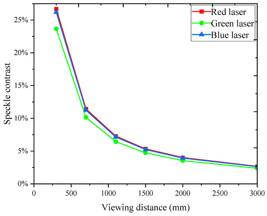
Figure 7.
RGB laser speckle contrast changes as a function of viewing distance.
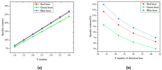
Figure 8.
RGB laser speckle contrast changes as a function of F-number of projection lens (a) and detector lens (b).
In the experiment, a projection engine design, as shown in Figure 3, is tested using the speckle contrast measurement system from OXIDE. When the testing distance is 700 mm and the F-number of the detector lens is 41.7, the RGB laser speckle contrasts are 9.1%, 7.3%, and 10.4%, respectively, as shown in Figure 9, which agrees with the theoretical calculation results depicted in Table 1. Meanwhile, the speckle contrast of the white field is also tested, and the result is 5.6%. According to the principles of color speckle calculation [17,18], the value of color speckle depends on both the RGB speckle contrast and the ratio of RGB brightness on a white field. The speckle contrast of the white field is
where , , , and represent the brightness of the RGB and white field, respectively, while , , and represent the RGB speckle contrast, respectively. The ratios of RGB brightness on a white field are 22.1%, 70.3%, and 7.6%, respectively, in the report. The speckle contrast of the white field is calculated as 5.55%, according to Equation (31), which agrees with the testing result of 5.6%.
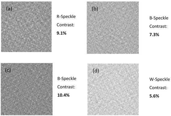
Figure 9.
The testing results show the RGBW laser speckle contrasts are 9.1%, 7.3%, 10.4%, and 5.6%, respectively, (a–d) represent the pictures of the RGBW laser speckle.
Simultaneously, in order to investigate the impact of detection range on speckle contrast, we conducted RGB laser speckle contrast measurements by varying the detection range at intervals of 300 mm/700 mm/1100 mm/1500 mm/2000 mm/3000 mm while maintaining a consistent experimental setup. The focus should be adjusted whenever there is a change in observation distance. Accurate measurement of speckle contrast value is only possible when the system is in focus. We had already adjusted the focus while testing the speckle contrast as a function of viewing distance. A test pattern should be projected onto a screen or the screen should be illuminated with an attached focus alignment pattern. The test chart may be any pattern that can be used to adjust focus.
The obtained results are presented in Figure 10. The speckle contrast decreases as the detection range increases, as demonstrated in Figure 11. This observation is consistent with our theoretical calculations, which indicate that an increase in viewing distance leads to a higher number of elements in the projection system and consequently results in a reduction in RGB laser speckle contrast. The speckle contrast becomes imperceptible when the viewing distance exceeds 2000 mm.
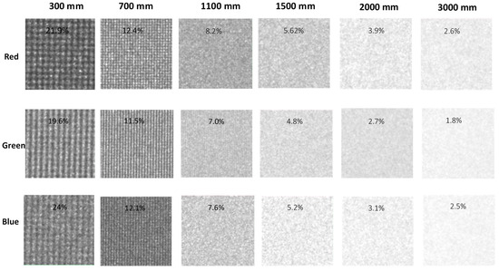
Figure 10.
The experimental results demonstrate that the speckle contrasts of the RGB laser exhibit variations in response to changes in the detection range.
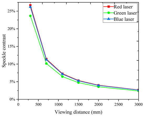
Figure 11.
The experimental results demonstrate that the speckle contrasts of the RGB laser decrease with increasing detection range.
The value of in the projection system also depends on the F-number and the focal length of the detector lens. The speckle contrast of the RGB laser was measured while varying the F-number of the detection lens, as illustrated in Figure 12. The increase in the F-number of the detection lens leads to an increase in the value of in the projection system, resulting in a decrease in speckle contrast. The testing results exhibit excellent agreement with our theoretical calculations, as depicted in Figure 13.
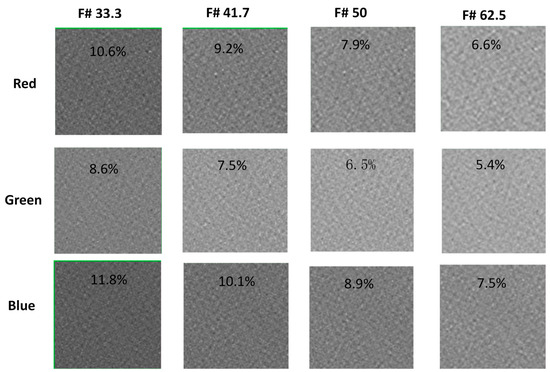
Figure 12.
The experimental results demonstrate that the speckle contrasts of the RGB laser vary as a function of the F-number of the detection lens.
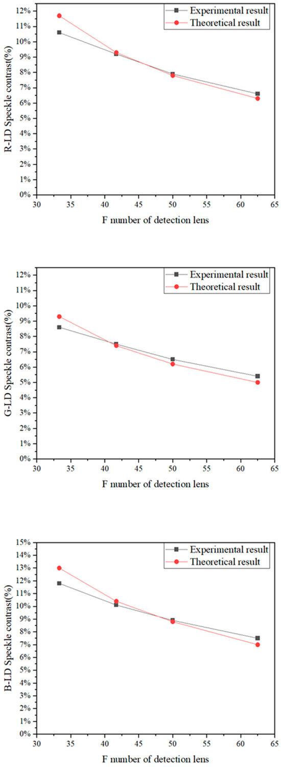
Figure 13.
The experimental and theoretical comparison of the impact of changing the F number on RGB laser speckle contrast.
4. Conclusions
The principle of speckle contrast in laser display and its influencing factors are investigated in this study through theoretical analysis. Furthermore, a formula for fitting the speckle contrast of laser projection displays is derived by considering various influencing factors. According to the speckle contrast formula, the speckle contrast in the laser projection display system is primarily determined by factors such as the light source’s wavelength, spectral width, screen surface roughness, and incidence and observation angles, as well as the number of independent speckle patterns, N, generated by diffuser rotation and the number of resolution elements within one eye resolution element in the projector lens. The speckle contrast diminishes progressively as the RGB spectral width expands, whereas it amplifies with a lengthier wavelength under constant spectral width. When the surface roughness exceeds the wavelength of the laser, the rough surface induces corresponding random fluctuations in the phase of light due to its inherent random fluctuations. The speckle contrast decreases as the surface roughness increases. The number of independent speckle patterns N is primarily determined by the dynamic diffuse rotation frequency in the projection system. However, beyond a certain threshold value of N, further increases have minimal impact on speckle contrast. The number of resolution elements within one eye resolution element in the projector lens depends on both the projection lens and viewing distance. The number of resolution elements within one eye resolution element in the projector lens is determined by both the characteristics of the projection lens and the viewing distance. The decrease in the F-number of the projection lens or an increase in viewing distance leads to an increase in the number of resolution elements within one eye resolution element, resulting in a reduction in speckle contrast.
In the experiment, a projection engine was tested using the speckle contrast measurement system provided by OXIDE. At a testing distance of 700 mm and with an F-number of 41.7 for the detector lens, the RGB laser speckle contrasts were measured to be 9.1%, 7.3%, and 10.4%, respectively, which aligns well with the results obtained from theoretical calculations. Meanwhile, the speckle contrast of the white field was also measured, yielding a result of 5.6%. In accordance with the principles of color speckle calculation, the report indicates that the relative brightness ratios of RGB on a white field are 22.1%, 70.3%, and 7.6%, respectively. The calculated speckle contrast for the white field is determined to be 5.55%, which aligns with the experimental measurement of 5.6%. The experimental results also demonstrate that the speckle contrasts of the RGB laser vary as a function of the F-number of the detection lens and the detection range. This observation is consistent with our theoretical calculations, which indicate that an increase in viewing distance or an increase in the F-number of the detection lens leads to a higher number of elements in the projection system and consequently results in a reduction in RGB laser speckle contrast. The speckle contrast becomes imperceptible when the viewing distance exceeds 2000 mm in our projection system.
Author Contributions
H.Z., Y.H., S.P. and Y.L.; methodology, H.Z. and Y.H.; software, S.P.; validation, H.Z. and S.P.; formal analysis, H.Z.; investigation, Y.H.; resources, H.Z.; data curation, H.Z.; writing—original draft preparation, H.Z.; writing—review and editing, H.Z. and Y.L.; visualization, H.Z.; supervision, Y.L.; project administration, H.Z.; funding acquisition, H.Z. and Y.L. All authors have read and agreed to the published version of the manuscript.
Funding
This research was found by the Project of Science and Technology of Sichuan Province (No. 2023ZDZX0021) and the Project of Science and Technology of Yi Bin (No. 2022CG004) and (No. 2021YGC02).
Institutional Review Board Statement
Not applicable.
Informed Consent Statement
Not applicable.
Data Availability Statement
The data presented in this study are available on request from the corresponding author.
Acknowledgments
We would like to acknowledge the support of the the Project of Science and Technology of Sichuan Province (No. 2023ZDZX0021) and the Project of Science and Technology of Yi Bin (No. 2022CG004) and (No. 2021YGC02).
Conflicts of Interest
Hongyou Zhang, Yu Hu, and Shuihai Peng were employed by XGIMI Projector Technology. The authors declare no conflicts of interest.
References
- Ochoa, E.; Goodman, J.W. Statistical properties of ray directions in a monochromatic speckle pattern. JOSA 1983, 73, 943–949. [Google Scholar] [CrossRef]
- Yu, N.E.; Choi, J.W.; Kang, H.; Ko, D.K.; Fu, S.H.; Liou, J.W.; Kung, A.H.; Choi, H.J.; Kim, B.J.; Cha, M.; et al. Speckle noise reduction on a laser projection display via a broadband green light source. Opt. Express 2014, 22, 3547–3556. [Google Scholar] [CrossRef] [PubMed]
- Kouno, Y.; Kamata, K.; Chihaya, K.; Sasaki, W.; Matsubara, H.; Hirano, A.; Nagashima, K. Effective speckle noise reduction of laser projection displays by high frequency driving current superposition for blue, red, and direct green emission laser diode. In Optical Systems Design 2012; SPIE: Bellingham, WA, USA, 2012; Volume 8550, pp. 477–486. [Google Scholar]
- Kinoshita, J.; Aizawa, H.; Takamori, A.; Yamamoto, K.; Murata, H.; Tojo, K. Angular dependence of screen speckle and fiber speckle of coupled output of nine high-power blue laser diodes through a multi-mode fiber. Opt. Rev. 2016, 23, 121–132. [Google Scholar] [CrossRef]
- Redding, B.; Choma, M.A.; Cao, H. Speckle-free laser imaging using random laser illumination. Nat. Photonics 2012, 6, 355–359. [Google Scholar] [CrossRef] [PubMed]
- Tong, Z.; Chen, X. Speckle contrast for superposed speckle patterns created by rotating the orientation of laser polarization. JOSA A 2012, 29, 2074–2079. [Google Scholar] [CrossRef] [PubMed]
- Akram, M.N.; Tong, Z.; Ouyang, G.; Chen, X.; Kartashov, V. Laser speckle reduction due to spatial and angular diversity introduced by fast scanning micromirror. Appl. Opt. 2010, 49, 3297–3304. [Google Scholar] [CrossRef] [PubMed]
- Svensen, Ø.; Chen, X.; Akram, M.N. Speckle reduction in laser projection displays through angle and wavelength diversity. Appl. Opt. 2016, 55, 1267–1274. [Google Scholar]
- Lowenthal, S.; Joyeux, D. Speckle removal by a slowly moving diffuser associated with a motionless diffuser. JOSA 1971, 61, 847–851. [Google Scholar] [CrossRef]
- Suzuki, K.; Kubota, S. Understanding the exposure-time effect on speckle contrast measurement for laser projection with rotating diffuser. Opt. Rev. 2019, 26, 145–151. [Google Scholar] [CrossRef]
- Wang, L.; Tschudi, T.; Halldorsson, T.; Petursson, P.R. Speckle reduction in laser projection systems by diffractive optical elements. Appl. Opt. 1998, 37, 1770–1775. [Google Scholar] [CrossRef] [PubMed]
- Kasazumi, K.; Kitaoka, Y.; Mizuuchi, K.; Yamamoto, K. A practical laser projector with new illumination optics for reduction of speckle noise. Jpn. J. Appl. Phys. 2004, 43, 5904. [Google Scholar] [CrossRef]
- Kartashov, V.; Akram, M.N. Speckle suppression in projection displays by using a motionless changing diffuser. JOSA A 2010, 27, 2593–2601. [Google Scholar] [CrossRef] [PubMed]
- Goodman, J.W. Speckle Phenomena in Optics: Theory and Applications; Roberts and Company Publishers: Greenwood Village, CO, USA, 2007. [Google Scholar]
- Kubota, S. Simulating the human eye in measurements of speckle from laser-based projection displays. Appl. Opt. 2014, 53, 3814–3820. [Google Scholar] [CrossRef] [PubMed]
- Roelandt, S.; Meuret, Y.; Jacobs, A.; Willaert, K.; Janssens, P.; Thienpont, H.; Verschaffelt, G. Human speckle perception threshold for still images from a laser projection system. Opt. Express 2014, 22, 23965–23979. [Google Scholar] [CrossRef] [PubMed]
- Kuroda, K.; Ishikawa, T.; Ayama, M.; Kubota, S. Color speckle. Opt. Rev. 2014, 21, 83–89. [Google Scholar] [CrossRef]
- Kinoshita, J.; Aizawa, H.; Takamori, A.; Yamamoto, K.; Murata, H.; Kuroda, K. 10-1: Color Speckle Evaluation Using Monochromatic Speckle Measurements. SID Symp. Dig. Tech. Pap. 2016, 47, 95–98. [Google Scholar] [CrossRef]
Disclaimer/Publisher’s Note: The statements, opinions and data contained in all publications are solely those of the individual author(s) and contributor(s) and not of MDPI and/or the editor(s). MDPI and/or the editor(s) disclaim responsibility for any injury to people or property resulting from any ideas, methods, instructions or products referred to in the content. |
© 2024 by the authors. Licensee MDPI, Basel, Switzerland. This article is an open access article distributed under the terms and conditions of the Creative Commons Attribution (CC BY) license (https://creativecommons.org/licenses/by/4.0/).