Abstract
To improve the accuracy of infrared radiation characteristics measurement in the aviation field, an infrared Fourier transform imaging spectrometer based on a double-swing solid angle reflector was designed. This imaging spectrometer operates in the 3–5 μm wavelength range and has a field of view of 1.7° × 1.7°. This article presents a comprehensive analysis of the system’s stray light and also studies the impact of external stray light on the imaging quality, along with the influence of internal stray light on the interference effects and the spectral resolution. It also present the design of a hood that suppresses the point source transmittance of the external stray light down to the order of 10−4. Based on this, we propose a method that incorporates the introduction of wedge and inclination angles. Additionally, a numerical range is provided for the addition of these angles on the beam splitter mirror and compensation plate. This ensures the effective suppression of any internal stray light. This study fills the gap in the knowledge about Fourier transform imaging spectrometers operating in the mid-infrared band for aviation applications, and proposes a suppression method suitable for interference systems, which is also suitable for Fourier transform imaging spectrometers based on other types of interferometers. This study broadens the application field of Fourier transform imaging spectrometers in stray light, and has great significance to promote the development of Fourier transform imaging spectrometer.
1. Introduction
At present, in modern aviation-based high-tech warfare, methods to enable the rapid identification of camouflage and false targets have become an important research field and a major application direction for military reconnaissance [1,2]. With the increasing demand for the application of imaging spectrometers in a variety of fields, the development of the Fourier transform imaging spectrometer [3,4,5,6] has also become a research hot spot. The fundamental task of the Fourier transform imaging spectrometer is to detect and acquire the image signal and the spectral function of a specific target [7,8]. During the target detection process, stray light, as a non-imaging beam that can be received by the detector [9], will cause degradation of the imaging quality of the optical system and will reduce the signal-to-noise ratio of the imaging spectrometer. To meet the technical requirements of the Fourier imaging spectrometer [10,11,12,13] and provide high performance, researchers are now paying increasing attention to the study of stray radiation.
As part of the complex development process for Fourier transform imaging spectrometers, the influence of stray light on these spectrometers and methods to suppress it have become an important research issue in several countries. Du et al. analyzed and calculated the stray light characteristics [14] of a spaceborne Fabry-Pérot interference imaging spectrometer operating in the visible band, and then suppressed the stray light in this system by adding a blocking stop to the system structure, thus reducing the stray radiation ratio effectively. Chen et al. from the Beijing Space Electromechanical Research Institute analyzed the effects of multiple reflections of stray light on the modulation regime [15,16] in a near-infrared band hyperspectral resolution Fourier transform spectrometer, and proposed the introduction of wedge angle and tilt angle suppression methods to separate the stray light spots from the normal light spots. Dussarrat et al. from the European Meteorological Satellite Organization analyzed the stray light present in the background of a Michelson interferometer in a far-infrared Fourier transform spectrometer [17] and proposed relevant correction methods for image processing. The research described above indicates that at this stage, there have been certain studies of stray light analysis for spaceborne visible, near infrared, and far infrared interference imaging spectrometers; various stray light suppression schemes have also been proposed for spectrometers with different structures, thus effectively reducing the effects of stray light on these optical systems. There have been few reports, however, on the analysis and suppression of the stray light in Fourier transform imaging spectrometers for use in the aviation field.
The purpose of this paper is to improve the imaging quality and spectral resolution of mid-infrared Fourier transform imaging spectrometers in the airborne aviation field, and analyze the influence of stray light on spectral resolution according to the potential situation in actual processing. In this paper, a new mid-infrared Fourier transform imaging spectrometer based on a double-oscillating solid angle reflector is proposed. To provide a comprehensive analysis of the impact of stray light on these systems, theoretical research is performed on both the stray light that occurs outside the field of view and the stray light within the system. By designing the internal and external hood and blocking rings for the Cassegrain telescope system, the external stray light is effectively suppressed. On this basis, the non-ideal transmission phenomenon inside the interference system is analyzed. The decrease in the contrast of interference fringes and spectral resolution caused by the reflected stray light produced by this phenomenon is studied. Finally, the scheme of introducing wedge angle and inclination angle is proposed. The theoretical research and analysis of this phenomenon is carried out, which can effectively suppress the influence of this phenomenon.
At present, the Beijing Space Electromechanical Research Institute has conducted stray light analysis and suppression on the visible to near-infrared band of the Fourier transform interferometer with high spectral resolution on Gaofen-5 [18], and finally obtained the impact of stray light on the contrast of interference fringes. In this paper, the stray light analysis and suppression of a Fourier imaging spectrometer in the mid-infrared band are carried out, and finally the influence of stray light on the contrast of interference fringes is further translated into the spectral resolution. Therefore, this study has a more direct application value for the spectral resolution index parameters of Fourier imaging spectrometer.
In this paper, the TracePro 7.4 software was used to trace the stray light path to study and analyze the stray light phenomenon. The designed model and the results will offer reference values for the development of spectrometers for military and civil applications. Moreover, the innovative design of the optical system and the analysis of stray light in this paper play a driving role in improving the imaging quality and spectral resolution of imaging spectrometers in military and civilian fields. The measurement accuracy of the radiation characteristics of the imaging spectrometer in the middle infrared band can be effectively improved.
2. Optical System
2.1. Solid Angle Mirror
The system proposed in this work uses a solid angle mirror rather than a plane mirror and omits the system for compensation of the plane mirror moving tilt [19] caused by vibrations. A solid angle mirror is an optical instrument consisting of three plane mirrors. The solid angle mirror is based on the law of light reflection and the structure of the angle reflector, when the light is incident on the angle mirror’s three mutually perpendicular reflecting surfaces, it will be reflected by the three plane mirrors and emitted in the opposite direction of the incident light. The structure diagram of the solid angle mirror is shown in Figure 1.
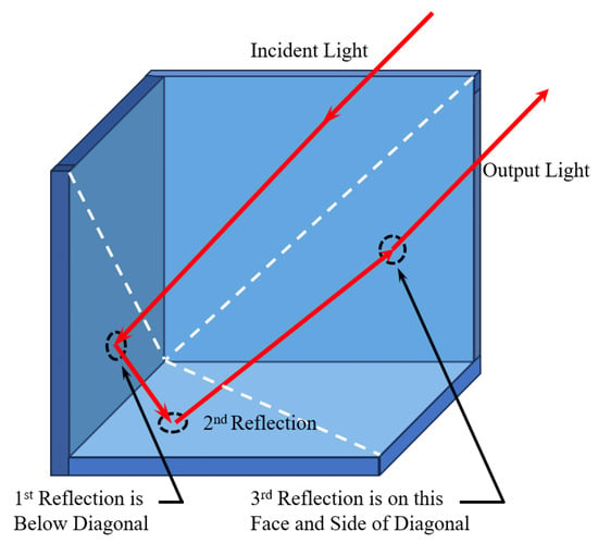
Figure 1.
Structure diagram of solid angle mirror.
2.2. The Front Telescope System
The front telescope system uses a Cassegrain coaxial folding transmission structure [20] to achieve high imaging quality and a compact structure; this structure also avoids the difficulties involved in the fabrication and processing of large-aperture transmissive optical infrared materials required by the conventional transmission system. The Cassegrain telescopic system structure is generally a reflective system composed of a primary mirror and a secondary mirror. The structure diagram of the Cassegrain telescopic system is shown in Figure 2.
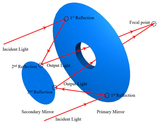
Figure 2.
Structure diagram of Cassegrain telescopic system.
As shown in the Figure 2, first, the primary reflector reflects and focuses light onto a single point, creating a sharp image. The secondary mirror then reflects this image onto the focal point of the telescope. By precisely designing and manufacturing the shape and position of the two mirrors, it is possible to ensure that the light remains focused after passing through the mirrors and a high-quality image is formed. To achieve compact size, Cassegrain telescope structures are typically designed with folded optical paths. This design reduces the length and diameter of the telescope, making it easier to transport and install.
Compared with the traditional transmission system, the Cassegrain system has the advantages of having a large aperture, long focal length, and small size, and being multi-band, colorless and so on. Therefore, it is widely used in aerial optical systems. The characteristics of common telescopic systems are compared as shown in Table 1.

Table 1.
Comparison of characteristics of common telescopic systems.
2.3. Overall Optical System
The interference system uses a swinging scanning structure [21] in place of the traditional translation and push sweep structure, which increases the optical path length and improves the spectral resolution; finally, the most commonly used silicon and germanium materials, which offer good stability and mature processing technology, are selected as the lens materials [22]. The proposed optical system consists of three parts: the front telescope system, the interference system, and the rear imaging system. A diagram of the optical system is shown in Figure 3.
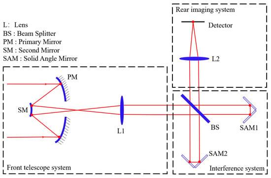
Figure 3.
Optical structure of the mid-wave infrared Fourier imaging spectrometer.
The front telescope system can achieve five times the beam contraction performance, and can collimate the beam into the interference system to match with the pupil plane of the interferometer. Then, by swinging the solid angle reflectors SAM1 and SAM2, the optical path is changed such that the beam interferes at the beam splitting system. The rear imaging system is a secondary imaging system that realizes 100% matching between the exit pupil and the cold stop of the detector [23]; the interference beam is then focused on the detector through the rear imaging system and forms continuously varying interference fringes. The parameters of the proposed optical system are listed in Table 2.

Table 2.
Parameters of the optical system for the medium-wave infrared Fourier imaging spectrometer.
The mechanical assembly diagram for this system is shown in Figure 4. Germanium was selected as the material for the beam splitter mirror and the compensation plate, and the surfaces of the primary and secondary mirrors and the solid angle mirrors of the Cassegrain telescope system are plated with gold films to achieve high reflection effects.
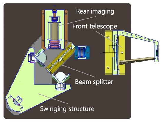
Figure 4.
Mechanical structure of the mid-wave infrared Fourier imaging spectrometer.
3. Stray Light Sources and Evaluation Criteria
3.1. Sources of Stray Light
Based on the characteristics of infrared imaging spectrometers and the analysis method used for stray light in traditional optical systems, the following potential sources of stray light were determined [24]: (1) Stray light can be caused by light originating outside the system’s field of view entering the optical system, which mainly comes from direct irradiation by sunlight, surface radiation, and atmospheric scattering. The stray light is formed after it reaches the image plane through the optical system, and this light is generally present in various imaging systems. (2) Imaging target stray light can originate within the field of view, i.e., imaging target light that reaches the image plane by passing through the system along an abnormal imaging path; this light is mainly generated from the imaging target light through residual reflection, scattering, and diffraction processes on the surfaces of the optical and structural elements.
3.2. Harm Caused by Stray Light
In the imaging optical system of an infrared Fourier imaging spectrometer, stray light will increase the noise that occurs on the image plane, and the stray light convergence point near the image plane will have a particularly serious impact on the imaging performance [25]. For the Michelson interferometer system, because the beam interference occurs inside the system, the quality of the interference effect becomes the main factor that affects the ability to recover the spectrum, and the interference fringe contrast [26] is one of the criteria used to evaluate the quality of the interference effect. When stray light is generated in the interference system through reflection processes, the interference phenomenon that occurs will be aliasing; the interference fringe contrast will then be reduced, and this will have a serious impact on the spectrum recovery capability.
3.3. Design of the Anti-Stray Light Structure
As part of the design of the anti-stray light structure, the external hood design must usually meet the following principles [27]: (1) non-imaging light should be prevented from reaching the image surface directly; (2) normal light from the edge field of view must not be blocked by the system hood; (3) strong stray light sources such as sunlight at angles greater than the avoidance angle may only enter the optical system after at least two or more scattering processes; (4) black coatings with high absorption rates should be used. The external hood design was thus completed according to the principles above. For a general Earth observation system, a first-level hood [28] can meet these requirements. The external hood used by the system proposed in this paper is shown in Figure 5.
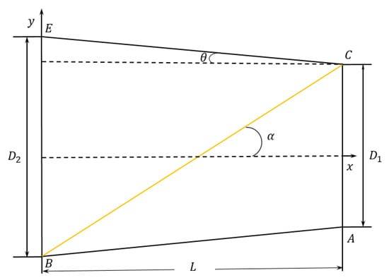
Figure 5.
Schematic design for the external hood.
The Sun’s avoidance angle is known to be 30°, is the system’s field of view angle and has a value of 0.8°, is the hood length, is the diameter of the inner aperture of the hood, i.e., the diameter of the system’s entrance pupil, and is the diameter of the outer aperture of the hood. The following relationships can be obtained from the geometric relationship shown in Figure 3:
When the system’s field of view angle = 0.8°, the entrance pupil diameter = 105 mm, and the avoidance angle = 30° are known, then values of = 110.20 mm and = 186.37 mm can be obtained using Equations (1) and (2).
Aviation imaging systems require a high stray light suppression effect and it is necessary to add a blocking ring inside the hood for these systems. The blocking ring can prevent stray light from being caused by multiple reflections inside the hood. The blocking ring usually takes the form of a black coating with a high absorption rate. The hood structure [29], when combined with a cylindrical outer wall and a conical inner wall, can effectively reduce the number of blocking rings required and increase the depth of these blocking rings, and it is thus highly conducive to the elimination of stray light; therefore, the structure shown in Figure 6 was used for the design of the blocking rings.
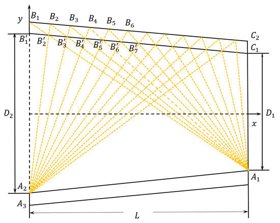
Figure 6.
Schematic diagram for the design of the inner blocking rings of the external hood.
Connecting the upper vertex of the external hood and the upper inner wall of the cone gives the first stop ring position; at the main mirror of the lower inner wall of the cone is then connected with at the edge of the external hood, and the intersection of this line with the upper inner wall of the cone at point is the second stop ring position. Then, by connecting , , and the upper wall of the external hood, which intersects at , and continuing in a similar manner, the positions of all of the blocking rings in the hood can be determined.
According to the design principle for the inner hood [30], the inner hood sizes for the primary mirror and the secondary mirror in this system will be determined using the focal length of the Cassegrain system, the focal length of the primary mirror, the positions of the stop and the back intercept, and other parameters. The design process is illustrated in Figure 7.
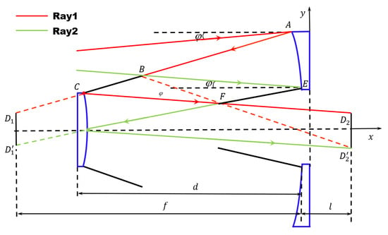
Figure 7.
Schematic of the design of the internal hood.
As shown in Figure 7, ray 1 and ray 2 are the two edge rays, is the half-field angle, is the distance between the primary mirror and the secondary mirror, is the focal length, and is the back intercept. The apex of the hood in the secondary mirror is the point of intersection of light rays 2 and 1 when reflected by the primary mirror, and the apex of the hood in the primary mirror is the point of the intersection of light ray 2, when reflected by the primary mirror, and light ray 1, when reflected by the primary mirror and the secondary mirror in turn.
The front aperture and the rear aperture of the hood in the primary mirror are 29.4 mm and 52.85 mm in diameter, respectively. The front aperture diameter of the secondary lens hood is 47.98 mm and the rear aperture diameter is 57.03 mm. ProE 5.0 software was used to model the hood. The stereogram designed for the external hood is shown in Figure 8a, and the stereogram for the inner hood is shown in Figure 8b.
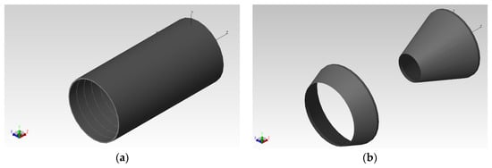
Figure 8.
Structural drawings of the hood. (a) External hood structure. (b) Inner hood structure.
3.4. Evaluation Criteria for Stray Light
The point source transmittance (PST) is a transfer function that is commonly used to describe the effects of stray light on optical systems [31]. The PST is equal to the total amount of stray light incident on the focal plane of an optical system divided by the total amount of light incident on the optical system that enters the pupil, and it can be calculated as follows:
In Equation (3), is the irradiance of the stray light on the focal plane and is the irradiance when the light emitted by a point light source located at infinity (through collimation) is incident on the plane perpendicular to the source. If the irradiance of the light source is normalized to 1, then the irradiance on the image surface is the .
4. Stray Light Analysis
4.1. Stray Light Model Establishment
At present, the software packages with stray radiation analysis functionality generally include LightTools 8.6, TracePro 7.4 and ASAP 2019, and among these packages, TracePro 7.4 software is compatible with ProE 5.0, SolidWorks 2023, and other mechanical design software. At the same time, TracePro 7.4 is also compatible with ZEMAX OpticStudio 2023 and CODE V 11.5 optical design software, and has a user-friendly operation interface [32]. TracePro 7.4 is a powerful lighting and optical design simulation software that simulates and analyzes the propagation and behavior of all kinds of light, including stray light. In TracePro 7.4, users can evaluate and analyze the effects of stray light by simulating the propagation and interaction of light in an optical system. This includes the simulation and analysis of light sources at different angles, reflections, and refractions of optical surfaces, internal and external scattering, etc. The comparison table of the functions of different stray light analysis software is shown in Table 3.

Table 3.
Comparison of functions of different stray light analysis software.
In this paper, TracePro software was used to simulate the optical surface and analyze the stray light, so that the source, degree and influence of stray light in the infrared Fourier imaging spectrometer designed in this paper can be understood, and different measures can be taken to reduce stray light according to different sources of stray light, and finally achieve the purpose of optimizing optical design.
4.2. Analysis of the System Stray Light
Reasonable settings and distributions of the surface properties of the different optical elements can provide better simulations of the actual situation. The specific parameters that were set in this process are listed in Table 4.

Table 4.
Optical surface parameter settings.
Because the optical system is located far away from the Sun, the Sun can be regarded as a point light source, and reverse light tracing is required to locate the important surfaces. The specific light source setting parameters are listed in Table 5. The positioning of the mirror is based on the origin of the axes.

Table 5.
Light source model settings.
As a result of the symmetry of the Cassegrain system, only the off-axis angle from 0° to 90° must be taken into account when analyzing the orientation of the sunlight. In this paper, the stray light analysis was performed on optical systems without optimization or with an added hood. The PST was analyzed for systems with off-axis angles ranging from 0° to 80°, and the PST of the solar radiation was calculated at various off-axis angles via ray tracing. The analysis results are shown in Figure 9.
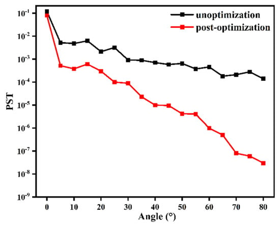
Figure 9.
Designs of the PST analysis curves before and after use of the hood.
Through a simulation analysis, it was found that in the system without the hood, the PST is mainly distributed with values of the order of , which will have a considerable impact on the imaging quality of the system. After the hood is set, the PST can be controlled to be within the order ranging from at angles between 25° and 70°, whereas at angles above 70°, the PST is basically controlled to be below the order of . The imaging effect of the system will be unaffected. The feasibility of the suppression scheme design proposed in this paper was verified by a data comparison process. The designs of the internal and external hoods and the blocking ring can suppress the influence of stray light on the system effectively to a certain extent.
5. Stray Light Interfering with the System
5.1. Establishment of an Interference Model
Because the core aspect of interference spectroscopy technology is the extraction of an interferogram, the interference effect becomes the key factor affecting the system’s spectral recovery capability. When incident light with the wave number interferes, the interference signal light intensity [33] satisfies the following equation:
In Equation (4), is the wave number of the light source, is the light intensity on the interference system’s reflected light path, is the light intensity on the interference system’s transmitted light path, is the optical path difference, is the half angle of the light source’s field of view, is the solid angle of the light source’s field of view, and .
The contrast of the interference fringes has become the standard used to evaluate the quality of the interference effect, and the contrast of the interference fringes is determined using the following equation:
In Equation (5), and are the maximum and minimum values of the light intensity , respectively.
In the Fourier transform imaging spectrometer [34], when incident light with the wave number interferes, Equation (4) can be substituted into Equation (5), and the equation for the interference fringe contrast is as follows:
In an ideal Fourier transform imaging spectrometer, where it is assumed that the ideal device does not absorb light, if , then if and only if , the interference fringe contrast is at a maximum. However, if , the interference fringe contrast will be affected, and then .
5.2. Simulation of an Ideal Interferogram
In this work, a monochromatic light source was used to verify the interference phenomenon in the optical system. A rectangular light source was selected in this case and the incident wave was a plane wave. The reflectance of the solid angle mirror was set to have the ideal value of 100%, and the transmittance and reflectance of the back surface of the beam splitter were both set at 50%. Finally, the interference phenomenon of the 4.44 μm wavelength beam in the optical system was simulated using simulation analysis software, and the ideal interferogram obtained is as shown in Figure 10, where the contrast of the interference fringe .
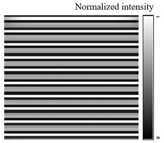
Figure 10.
Ideal interferogram.
5.3. Michelson Interferometer Stray Light Analysis
Because the Fourier transform imaging spectrometer is based on the working principle of the Michelson interferometer [35], the corresponding spectral diagram is obtained by performing a Fourier transform on the interferogram obtained from the interference, and this means that the interference effect will affect the spectral recovery accuracy of the imaging spectrometer directly. However, the transmittance values of the beam splitter and the compensator in the interference system cannot reach their ideal 100% values during actual processing. Therefore, multiple reflections will occur between the beam splitter and the compensator, and the stray light formed by these reflections will enter the design field of view parallel to the normal light; this stray light cannot be filtered out by the cold stop, and will then affect the interference modulation system, leading to reduced spectral resolution. The stray light path obtained by this reflection process is as shown in Figure 11.
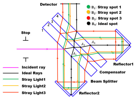
Figure 11.
Schematic diagram of the stray light path.
As shown in Figure 11, when the transmittance values of the beam splitter and the compensator cannot reach their ideal values of 100%, the light that enters the interference system will be reflected at points , , and at surfaces 1, 3, and 4, respectively, thus forming new stray light beams that enter the detector, in which these beams cross with the light from different fields of view; this affects both the imaging quality of the system and the interference effect of the system. Assuming again that the ideal optical device does not absorb light, the reflectivity values of surface 1, surface 3, and surface 4 are given by 100% minus their transmittance. We therefore simulated the actual processing conditions. As shown in Table 6, the different transmittance values of beam splitter surface 1 and compensator surfaces 3 and 4 were set within the range from 95% to 100%. The other lenses in the system were set at the ideal transmittance of 100%.

Table 6.
Transmittance setting table for different anti-reflection coatings on opposing sides 1, 3, and 4.
The optical path shown in Figure 11 was simulated and the corresponding interference graphs generated under the different transmittance conditions are shown in Figure 12.
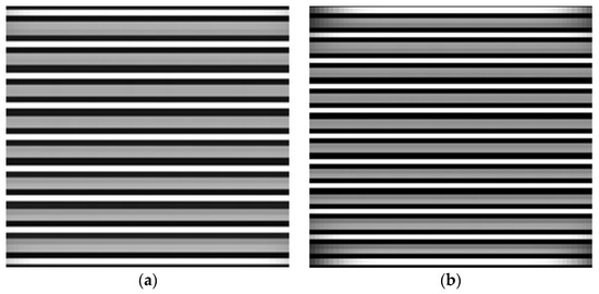
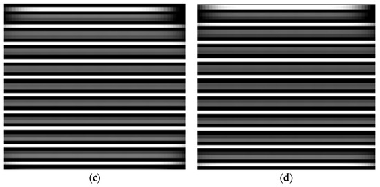
Figure 12.
Interferograms generated by the optical system at different transmittance values. (a) T = 99%; (b) T = 98%; (c) T = 97%; and (d) T = 96%.
The maximum value of the light intensity and the minimum value of the light intensity corresponding to the interference fringes were obtained via a simulation analysis, and were then substituted into Equation (6) to perform the calculations. The calculated data were then sorted and used to draw a dot plot, as shown in Figure 13.
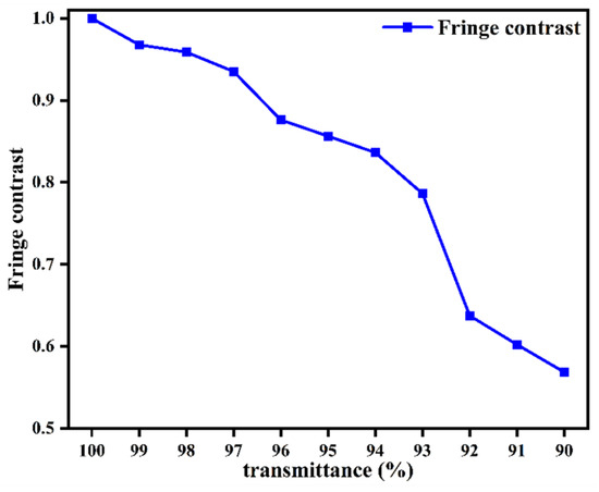
Figure 13.
Curve of fringe contrast versus transmittance.
The analysis results show that when the transmittance decreases, the contrast of the interference fringes also decreases. This occurs because the stray light caused by the reflection from the beam splitter mirror and compensating mirror surfaces causes the interference beams to begin aliasing, and the contrast of the interference fringes then decreases. Spectral restoration was performed on the interferogram with the appropriate transmittance to obtain the corresponding spectrum at the central wavelength of 4.44 μm, as shown in Figure 14c. Other parameters remain unchanged. Under different transmittance conditions, the interferograms with wavelengths of 3.64 μm, 4.00 μm, and 5.00 μm are transformed by Fourier transform, and the restored spectral diagrams are shown in Figure 14a,b,d.
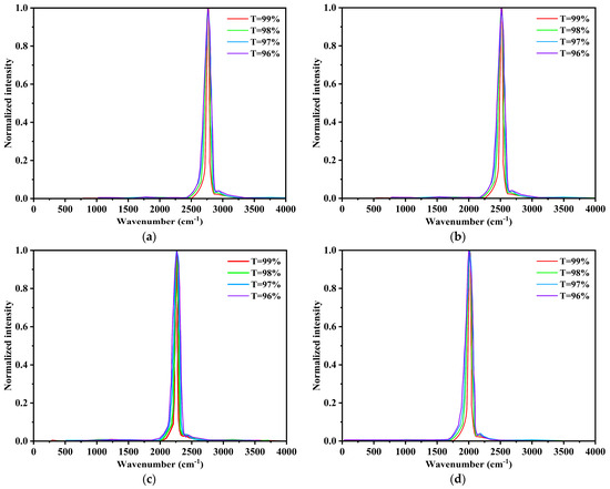
Figure 14.
Recovery spectral curve of interferograms with different transmittance and wavelength: (a) 3.64 μm; (b) 4.00 μm; (c) 4.44 μm; and (d) 5.00 μm.
As shown in Figure 14a–d, the half-peak width of the reconstructed spectral line gradually increases with decreasing T, and the spectral resolution then gradually decreases. The analysis results show that as the transmittance decreases, the fringe contrast also decreases, and the spectral resolution decreases in turn.
In order to eliminate the influence of reflected stray light on the contrast of interference fringes and spectral resolution, it can be designed to separate the reflected stray light from the spot of the normal optical path. In this paper, wedge angle and inclination angle are introduced into the beam splitter and compensator to eliminate the influence of reflected stray light on the contrast and spectral resolution of interference fringes. The wedge angle and inclination angle of the beam splitter and compensator can make the reflected stray light path no longer parallel to the normal light path. When the angle between the reflected stray light path and the normal light path is greater than the field of view angle of the interferometer, the stray light can be separated from the normal light.
5.4. Increase the Wedge Angle and Inclination Angle to Eliminate Multiple Reflections of Stray Light Design
In order to eliminate the reflected stray light, the beam splitter and compensator increase the wedge angle, and the compensator increases the inclination angle. According to the requirements of the optical path equivalent post-parallel plate for transmitted and reflected light paths, the placement mode of the beam splitter and compensator after increasing the wedge angle and inclination angle is shown in Figure 15. The wedge angle of the beam splitter is equal to the wedge Angle of the compensator, and the inclination angle of the compensator is , is the angle of the incident light, and is the refractive index of germanium metal (in the infrared range, germanium has a refractive index of about 4.0).
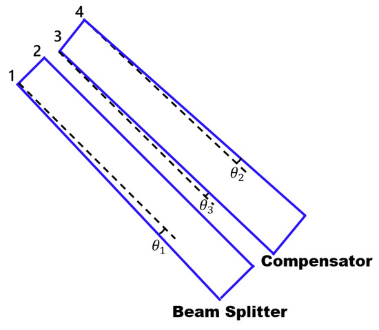
Figure 15.
Diagram of placement of beam splitter and compensator.
In order to eliminate the influence of stray light reflected by surfaces 1, 3, and 4 on the interference system, the spot of this stray light should be deviated from the spot of the normal optical path.
The stray light path is shown by the green line in Figure 11. The relation between the angle , , and wedge angle of the stray light reflected by surface 1 and the normal optical path is shown in Equations (7) and (8):
The stray light path is shown by the yellow line in Figure 11. The relation between the angle , , and wedge angle of the stray light reflected by surface 3 and the normal optical path is shown in Equations (9) and (10):
The stray light path is shown by the red line in Figure 11. The relation between the angle , , and wedge angle of the stray light reflected by surface 4 and the normal optical path is shown in Equations (11) and (12):
In the reflected stray light, with the increase in the number of reflections, the angle between the stray light and the normal light path will increase, so as long as the angle between the reflected stray light and the normal light path is greater than the angle of the field of view, the higher order reflected stray light can also be separated from the normal light path. In order to separate the spot that reflects stray light from the spot of the normal light path, the following conditions must be met: = > 2ω, = > 2ω, > 2ω, and > 2ω, ω is the field angle of the interferometer. When is taken, and the value range of wedge angle and inclination angle can be calculated according to Formulas (7)–(12): = > 0.2 °, > 0.8 °.
5.5. A Flow Chart of the Whole Simulation Work
In the whole simulation process, the optical and mechanical structure of the system is first designed, and then the physical model is established in TracePro 7.4 software, and the relevant parameters and conditions are set. Finally, the external stray light and the internal stray light of the interference system are analyzed by simulation, and the corresponding stray light suppression scheme is proposed. The simulation flow chart of the overall work is shown in Figure 16.
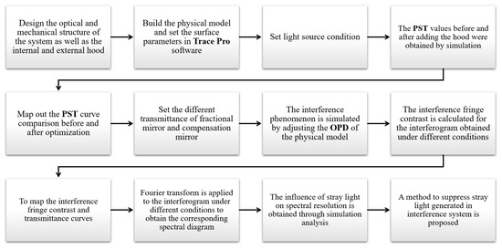
Figure 16.
A flow chart of the whole simulation work.
6. Conclusions
In this paper, the stray radiation sources of a Fourier transform imaging spectrometer for use in the airborne mid-infrared band are discussed, and the external stray radiation and the internal stray light characteristics of the interference system are studied in depth. In this paper, the PST is used as an index to evaluate the suppression level of the stray solar radiation. An optical-mechanical simulation model and a light source simulation model were established using TracePro software, and ray tracing was performed. The image plane irradiance and the system of the stray solar radiation were calculated, the system hood was designed, and its shading effect was analyzed. In addition, the influence of stray light from internal reflections on the contrast of the interference fringes was simulated and analyzed, and corresponding improvement measures were proposed. The results showed that when the off-axis angle was greater than or equal to 25°, the stray solar radiation on the phase surface was very small, and the order of magnitude of the system transmittance was less than or equal to . When the off-axis angle was greater than or equal to 70°, the solar stray radiation could be suppressed completely. For stray light caused by internal reflections from the interference system, the spectral resolution decreases as the magnitude of this stray light increases; a scheme for the addition of a wedge angle and an inclination angle to the beam splitter mirror and the compensating mirror is proposed in this work. It is deduced theoretically that when the wedge angle = > 0.2° and when the inclination angle > 0.8°, stray light spots inside the interference system can be separated from the light spots obtained from the normal light path, thus reducing the influence of internally reflected stray light on the interference fringe contrast.
7. Discussion
In this study, we have undertaken a comprehensive examination of the stray light associated with a custom-designed mid-infrared Fourier transform imaging spectrometer. By implementing internal and external hoods in combination with a blocking ring for the Cassegrain telescope system, we mitigated stray light outside the field of view effectively, thus leading to enhanced imaging quality. Our analysis of the stray light within the interference system showed that as the transmittance of the beam splitting system decreases, the contrast of the interference fringes also diminishes, and this ultimately results in a reduction in the spectral resolution of the corresponding spectra. The root cause of this phenomenon lies in the fact that, during practical processing, the ideal transmittance of 100% for the optical lenses cannot be achieved. Consequently, reflected stray light appears on the non-ideal transmission surfaces; this stray light persists within the field of view and cannot be filtered out using the detector’s cold diaphragm. This stray light introduces aliasing into the interference light, which then leads to the observed non-ideal transmission phenomenon. To address this issue, we used a method that involved the introduction of wedge and inclination angles to the beam splitter mirror and the compensation plate. This approach was successful in deflecting stray light out of the field of view of the cold diaphragm, thus effectively separating the stray light spot from the interference spot.
In terms of the limitations of the proposed methodology, the analysis of the stray light inside the interference system for the mid-infrared Fourier transform imaging spectrometer under study in this paper was limited to an analysis of the Michelson interferometer structure. Although beam splitting systems exist in most interferometers, based on the results of this research, the stray light analysis of infrared Fourier transform imaging spectrometers based on other interferometer structure types has not yet been verified, which will become the main direction of our future work, which has great significance for the comprehensiveness of the stray light analysis of Fourier transform imaging spectrometers.
In terms of the application field, the aim of this research is to solve the problems of performing quantitative measurements of mid-wave infrared radiation characteristics in the aviation field; therefore, the measurement range is limited to the mid-infrared spectral band from 3 to 5 µm, and the measurements of the visible light to near infrared band and the far infrared band are limited. We intend to continue to meet the challenges in the research into multispectral Fourier transform imaging spectrometers in our future work. The aim of this work is to improve the measurement accuracy, expand the application range, and reduce the limitations of the equipment.
Author Contributions
Conceptualization, methodology, software, formal analysis, investigation, writing—original draft preparation, visualization, C.B.; resources, L.M.; data curation, H.C.; writing—review and editing, X.Y.; supervision, H.S.; project administration, P.J. All authors have read and agreed to the published version of the manuscript.
Funding
This research was funded by the innovation project of the Changchun Institute of Optics, Fine Mechanics and Physics, Chinese Academy of Sciences (CXJJ-22S014).
Institutional Review Board Statement
Not applicable.
Informed Consent Statement
Not applicable.
Data Availability Statement
No new data were created or analyzed in this study. Data sharing is not applicable to this article.
Conflicts of Interest
The authors declare no conflicts of interest.
References
- Shen, H.H.; Huang, M.; Li, J.Q.; Liu, J.H.; Dai, M.; Jia, P. Recent progress in aerial electro-optic payloads and their key technologies. Chin. Opt. 2012, 5, 20–29. [Google Scholar]
- Lu, K.; Li, H.; Lin, L.; Zhao, R.; Liu, E.; Zhao, R. A Fast Star-Detection Algorithm under Stray-Light Interference. Photonics 2023, 10, 889. [Google Scholar] [CrossRef]
- Jiang, H.; Niu, X. Stray Light Analysis and Suppression of the Visible to Terahertz Integrated Cloud Detection Optical System. Sensors 2023, 23, 4115. [Google Scholar] [CrossRef] [PubMed]
- Tao, H.; Lv, J.; Liang, J.; Zhao, B.; Chen, Y.; Zheng, K.; Zhao, Y.; Wang, W.; Qin, Y.; Liu, G.; et al. Polarization Snapshot Imaging Spectrometer for Infrared Range. Photonics 2023, 10, 566. [Google Scholar] [CrossRef]
- Wang, N.; Wu, J.H.; Meng, H.; Gao, J.B. Performance of a long-wave infrared Fourier Transform imaging spectrometer using a corner-cube Michelson interferometer and an uncooled microbolometer array. In Proceedings of the AOPC 2015: Optical and Optoelectronic Sensing and Imaging Technology, Beijing, China, 15 October 2015. [Google Scholar]
- Revercomb, H.E.; Sromovsky, L.A.; Fry, P.M.; Best, F.A.; LaPorte, D.D. Demonstration of imaging Fourier Transform Spectrometer (FTS) performance for planetary and geostationary Earth observing. In Proceedings of the Hyperspectral Remote Sensing of the Land and Atmosphere, Sendai, Japan, 8 February 2001. [Google Scholar]
- Soucy, M.A.; Chateauneuf, F.; Deutsch, C.; Etienne, N. ACE-FTS instrument detailed design. In Proceedings of the Earth Observing Systems VII, Seattle, WA, USA, 24 September 2002. [Google Scholar]
- Matallah, N.; Sauer, H.; Goudail, F.; Fontanella, J.C.; Ferrec, Y.; Taboury, J.; Chavel, P. Design and first results of a Fourier Transform imaging spectrometer in the 3–5 µm range. In Proceedings of the Optical Design and Engineering IV, Marseille, France, 21 September 2011. [Google Scholar]
- Hu, B.L. Review of the development of interferometric spectral imaging technology (invited). Acta Photonica Sin. 2022, 51, 751401. [Google Scholar]
- Wu, C.K.; Zhang, W.; Hao, Y.Z. Design of a control system for a visible/near-infrared real-time imaging spectrometer. Chin. Opt. 2022, 15, 348–354. [Google Scholar]
- Grotevent, M.J.; Yakunin, S.; Bachmann, D.; Romero, C.; de Aldana, J.R.V.; Madi, M.; Calame, M.; Kovalenko, M.V.; Shorubalko, I. Integrated photodetectors for compact Fourier-transform waveguide spectrometers. Nat. Photonics 2023, 17, 59–64. [Google Scholar] [CrossRef]
- Afara, I.O.; Shaikh, R.; Nippolainen, E.; Querido, W.; Torniainen, J.; Sarin, J.K.; Kandel, S.; Pleshko, N.; Töyräs, J. Characterization of connective tissues using near-infrared spectroscopy and imaging. Nat. Protoc. 2021, 16, 1297–1329. [Google Scholar] [CrossRef]
- Wang, H.; Chen, Q.; Ma, Z.; Yan, H.; Lin, S.; Xue, Y. Development and prospect of stray light suppression and evaluation technology(Invited). Acta Photonica Sin. 2022, 51, 0751406. [Google Scholar]
- Du, S.S.; Wang, Y.M.; Du, G.J.; Wang, Y.-J. Stray light analysis of Fabry-Perot interference imaging spectrometer. J. Appl. Opt. 2009, 30, 246–251. [Google Scholar]
- Chen, F.; Gao, C.; Xu, P.M. Analysis of stray light influence to modulation on fourier transform spectrometer. Spectrosc. Spectr. Anal. 2018, 38, 2966–2970. [Google Scholar]
- Chen, F.; Gao, C.; Bai, J. Thickness matching design between splitter and compensator high spectral resolution Fourier transform spectrometer. Spectrosc. Spectr. Anal. 2020, 40, 3941–3945. [Google Scholar]
- Dussarrat, P.; Deschamps, G.; Dehnavi, S. Impact of straylight in Michelson Fourier transform spectrometers. In Proceedings of the International Conference on Space Optics—ICSO 2022, Dubrovnik, Croatia, 12 July 2023. [Google Scholar]
- Fan, B.; Chen, X.; Li, B.C.; Zhao, Y. Technical innovation of optical remote sensing payloads onboard GF-5 satellite. Infrared Laser Eng. 2017, 46, 0102002. [Google Scholar] [CrossRef]
- Feng, M.C.; Xu, L.; Wang, Y.J. Analysis and simulation of moving mirror tilt in michelson interferometer. Laser Optoelectron. Prog. 2021, 58, 0122001. [Google Scholar] [CrossRef]
- He, L.; Wang, R.H.; Hou, B.; Si, H.; Yang, K.; Hu, H. Athermalization design of a low-cost medium-wave infrared optical system based on Si/Ge material. Infrared Technol. 2023, 45, 527–533. [Google Scholar]
- Byun, W.J.; Kim, K.S.; Kim, B.S.; Lee, Y.S.; Song, M.S.; Choi, H.D.; Cho, Y.H. Multiplexed Cassegrain Reflector Antenna for Simultaneous Generation of Three Orbital Angular Momentum (OAM) Modes. Sci. Rep. 2016, 6, 27339. [Google Scholar] [CrossRef] [PubMed]
- Oishi, Y.; Sawada, Y.; Kamei, A.; Murakami, K.; Nakamura, R.; Matsunaga, T. Impact of Changes in Minimum Reflectance on Cloud Discrimination. Remote Sens. 2018, 10, 693. [Google Scholar] [CrossRef]
- Zhu, J.L.; Zhang, P.; Li, G.; Wei, X.; Fei, C.; Gan, J.; Yuan, Y.; Ji, Y. Stray light analysis of low-level-light optical system with LightTools software. J. Appl. Opt. 2022, 43, 1061–1065. [Google Scholar]
- Li, J.; Yang, Y.; Qu, X.; Jiang, C. Stray Light Analysis and Elimination of an Optical System Based on the Structural Optimization Design of an Airborne Camera. Appl. Sci. 2022, 12, 1935. [Google Scholar] [CrossRef]
- Wei, L.; Yang, L.; Fan, Y.-P.; Cong, S.-S.; Wang, Y.-S. Research on Stray-Light Suppression Method for Large Off-Axis Three-Mirror Anastigmatic Space Camera. Sensors 2022, 22, 4772. [Google Scholar] [CrossRef]
- Zhang, X.; Zhu, J.; Huang, L.; Zhang, Y.; Wang, H.; Li, H.; Guo, F.; Deng, J. Hyperspectral Channel-Modulated Static Birefringent Fourier Transform Imaging Spectropolarimeter with Zoomable Spectral Resolution. Photonics 2023, 10, 950. [Google Scholar] [CrossRef]
- Li, Y.Y.; Liu, L.; Peng, Q.; Yang, J. Stray radiation analysis of cassegrain system. Laser Infrared 2019, 49, 987–991. [Google Scholar]
- Jiang, S.W.; Xia, Z.T.; Sun, Y.X.; Wang, K. Optical Design and Stray-Light Analysis of Urban Night-Light Remote Sensing Imaging System. Laser Optoelectron. Prog. 2020, 57, 206–213. [Google Scholar]
- Chen, X.; Hu, C.H.; Yan, C.X.; Kong, D.C. Analysis and suppression of space stray light of visible cameras with wide field of view. Chin. Opt. 2019, 12, 678–685. [Google Scholar] [CrossRef]
- Li, J.; Meng, X.; Xu, D.; Song, H.; Wang, L.; Zhu, R. Near-infrared Fourier transform imaging spectrometer for remote sensing. In Proceedings of the International Symposium on Optoelectronic Technology and Application 2014: Imaging Spectroscopy; and Telescopes and Large Optics, Beijing, China, 18 November 2014. [Google Scholar]
- Key, R.; Sander, S.; Eldering, A.; Blavier, J.F.; Bekker, D.; Manatt, K.; Rider, D. The Geostationary Fourier Transform Spetrometer. In Proceedings of the 2012 IEEE Aerospace Conference, Big Sky, MT, USA, 3–10 March 2012. [Google Scholar]
- Liu, Y.N. Development of hyperspectral imaging remote sensing technology. J. Remote Sens. 2021, 25, 439–459. [Google Scholar] [CrossRef]
- Dong, X.; Xu, P.M.; Hou, L.Z. Design and Implementation of Atmospheric Infrared Ultra-spectral Sounder. Spacecr. Recovery Remote Sens. 2018, 39, 29–37. [Google Scholar]
- Wang, S.; Yetisen, A.K.; Wang, K.; Jakobi, M.; Koch, A.W. Dependence of the Michelson Interferometer-Based Membrane-Less Optical Microphone–Photoacoustic Spectroscopy Gas-Sensing Method on the Fundamental Parameters of a Photoacoustic Gas Cell. Photonics 2023, 10, 888. [Google Scholar] [CrossRef]
- Louis, M.; Frédéric, G.; Stéphane, L.; Raphaël, D.; Marc-André, S. An interferometer for compact imaging spectrometer. In Proceedings of the Imaging Spectrometry XII, San Diego, CA, USA, 12 September 2007. [Google Scholar]
Disclaimer/Publisher’s Note: The statements, opinions and data contained in all publications are solely those of the individual author(s) and contributor(s) and not of MDPI and/or the editor(s). MDPI and/or the editor(s) disclaim responsibility for any injury to people or property resulting from any ideas, methods, instructions or products referred to in the content. |
© 2024 by the authors. Licensee MDPI, Basel, Switzerland. This article is an open access article distributed under the terms and conditions of the Creative Commons Attribution (CC BY) license (https://creativecommons.org/licenses/by/4.0/).