1. Introduction
A synthetic aperture radar (SAR) is a sensor capable of two-dimensional imaging and is currently widely used on various types of platforms, such as spaceborne SARs, missile-borne SARs, and airborne SARs. Substantial research has been conducted on these subjects. In Ref. [
1], the author provides new insights into the alternating transmitting mode of spaceborne bistatic multichannel SARs. In Ref. [
2], the author designs a simulation software system for missile-borne SARs; however, SARs are not yet sufficiently mature for implementation on airborne platforms [
2] in some ways. In this paper, the large squint algorithm of airborne terahertz SARs is researched. Airborne SARs often need to operate with a large squint during the terminal guidance phase, a fact which has led to traditional SAR algorithms no longer being applicable to airborne SARs [
3,
4,
5,
6]. In addition, although imaging by terahertz SAR effectively results in an improved imaging resolution, it is more likely to be affected by the motion of the radar platform which requires a certain amount of motion compensation for the echo signals [
7,
8].
The front-squint-view SAR imaging method is the main focus of airborne SAR imaging research and has been investigated by many scholars. In Ref. [
2], the author analyzes the flight path of the missile and proposes a large-squint SAR imaging method, designing a simulation software for missile-borne SARs. However, the software can only perform simulation experiments, not actual measurements. Additionally, the transmitting signal utilizes a lower-frequency band without accounting for the potential motion error of the platform. In Ref. [
9], the author proposes an enhanced Doppler beam sharpening (DBS) algorithm to achieve large-squint imaging for airborne radars. However, in said paper, simulation experiments are performed only on point targets; the algorithm is also not validated with actual measurement data, meaning that its imaging effect is not fully reflected. Compared to the previous methods, the imaging method proposed in this paper is validated with actual data, and the imaging results exhibit a higher imaging resolution, a higher main lobe, and a lower side lobe, reflecting the better imaging performance of the method.
In this paper, the carrier frequency of the transmitting signal was set in the terahertz band, an approach which can effectively improve the transmitting signal bandwidth and imaging resolution. A terahertz wave refers to an electromagnetic wave with a frequency of 0.1~10.0 THz, falling between the microwave frequency band and the infrared frequency band [
10]. Owing to the large bandwidth of terahertz radar transmitting signals, it is possible to realize high-resolution imaging of a target. However, compared to the traditional low-frequency band SAR imaging signal processing, terahertz band SAR imaging is more susceptible to the motion error generated by the radar platform’s motion; therefore, it is necessary to research a compensation method for the motion error of the radar platform. In Ref. [
7], the author proposes a variety of motion error compensation methods for side-looking terahertz SAR imaging, but fails to consider imaging under large squint conditions. This paper presents an enhanced version of the compensation method that processes the echo signal with a range migration correction before estimating the motion parameters, enabling the radar to image the target under large squint conditions, effectively compensating for the motion error.
This paper proposes a motion compensation method for terahertz SAR imaging with a large squint. On the one hand, compared to the large-squint SAR imaging method proposed in Ref. [
2], the method proposed in this paper can achieve a higher resolution. On the other hand, compared to the motion error compensation methods proposed in Ref. [
7], the proposed method incorporates an additional portion of the range migration correction into the process, allowing for large-squint imaging and better focusing of the resulting image. The remainder of this paper is organized as follows. The signal model of the SAR algorithm is proposed in
Section 2.
Section 3 presents the motion error compensation method, from which imaging results are drawn and presented in
Section 4.
2. Large-Squint Terahertz SAR Imaging Method
Large-squint imaging typically refers to imaging conducted at squint angles between 30° and 60°. It is necessary to correct the range migration caused by the large squint before performing motion error compensation. As shown in
Figure 1, the radar platform on point
is heading in the y-axis direction at a speed of
, the black arrow is the direction of the platform. The target is located underneath the platform, on point
; dash lines
and
represent the range and instantaneous range, respectively. The term
represents the squint angle of the target.
Suppose that a linear frequency-modulated (LFM) signal is transmitted by the radar, which can be expressed as:
where
denotes the fast time,
is the carrier frequency,
denotes the pulse width, and
stands for the chirp rate of the signal [
11]. The radar echo signal obtained from the transmitted LFM signal after reflection from a ground target is:
where
is the time at which the center of the beam scans over the target,
denotes the slow time, and
is the synthetic aperture time of the target.
The range between the antenna phase center and the target at any time is:
A Taylor series expansion of (3) is performed when
, as follows:
Accordingly, the expression for the range migration is as follows:
The range dimensional Fourier transform is first performed on the echo signal to transform the signal into the range frequency domain for range walk correction. The expression for the range walk correction function is given by Equation (6):
The Doppler center can be corrected to zero after the range walk correction, at which point the phase of the echo signal can be expressed as:
Then, the echo signal is subjected to a range pulse compression, and the range pulse compression expression is given by Equation (9):
The signal, after the range pulse compression, is expressed as:
After applying the azimuthal Fourier transform to (10), the two-dimensional frequency-domain expression of the echo signal can be obtained as follows:
where
is the Doppler center frequency of the signal.
Thus, the range compression correction function can be expressed as:
After the range compression correction, the echo signal is subjected to a two-dimensional inverse Fourier transform, at which point the time-domain signal is expressed as:
At this point, the signal can be effectively focused on the range dimension, and the next section investigates motion compensation methods in the azimuth dimension.
3. Motion Error Analysis and Compensation Method
The motion error researched in this paper refers to the translational motion error caused by the motion velocity. Translational motion errors include the macroscopic motion error with a lower frequency and a larger amplitude and the vibration error with a higher frequency and a smaller amplitude. These two errors are called low-frequency motion error and high-frequency vibration error, respectively.
As the main focus of traditional microwave band SAR motion compensation research, the low-frequency motion error has been widely and deeply studied. A large number of studies have proposed effective compensation methods for the low-frequency motion error [
12,
13,
14]. In traditional microwave-band SAR imaging, the high-frequency vibration error is usually ignored, as it is smaller than the emission wavelength and has less influence on the echo phase. In terahertz SAR imaging processes, the wavelength of the emitted signal is typically short and close to the amplitude of the high-frequency vibration error of the platform; therefore, the effect of the vibration error of the platform has to be considered [
7].
As shown in
Figure 2, point
is the initial position of the platform and point
is the position of the platform at the moment
. The wave line represents the vibration trajectory of the platform. The vibration of the radar platform
is represented as a superposition of several simple harmonic motions, as expressed in Equation (17):
where
denotes the number of vibration components,
stands for the amplitude of the
i-th vibration component, and
and
represent the frequency and phase of the
i-th vibrational component, respectively.
The motion error is the superposition of the low-frequency error and the high-frequency error, and the expression is as follows:
where
is the low-frequency motion error, which is not considered for the moment.
Bringing the motion error into the expression of the echo signal (16) gives the following:
where
is related to the direction of the high-frequency error and is ordinarily taken as a constant [
7].
At this time, the echo signal has the form of a sinusoidal frequency modulation (SFM) signal. The parameters of the motion error , such as and , can be obtained from the SFM signal through the Radon transform.
As shown in
Figure 3, the arrow represents the process of Radon transform. A straight line can be converted into a point through the Radon transform that contains the parameters of the line. Based on
Figure 3, the Radon transform is defined in Equation (20) as follows:
After the Radon transformation, a point is converted into a sinusoidal curve in the
space, as shown in
Figure 4. The arrow represents the process of Radon transform. The amplitude and phase of the obtained sinusoidal curve are
and
, respectively.
Since the echo signal, at this time, is an SFM signal, a short-time Fourier transform (STFT) can be performed on the signal to obtain the time–frequency diagram of the signal. Then, the amplitude and phase of the vibration can be obtained by performing an inverse Radon transform on the signal. The parameters of
in (18) can be estimated as follows:
where
is the modulation frequency taken when the concentration of the transformation result is at its highest and the term
is the location of the maximum value in the transformation result.
After estimating the vibration parameters from the echo signal, a compensation function can be constructed to compensate for the motion errors. The compensation function is as follows:
The final imaging result can be expressed as:
4. Results
A single point target was first set up and a motion error component added to its echo signal according to (18) and (19) to verify the effect of the motion error on the imaging results. The major imaging parameters are shown in
Table 1. The single-point target imaging results after adding the motion error are shown in
Figure 5.
Motion errors can produce false targets on either side of the target in the azimuth dimension. The amplitude peak value of the outermost false target and its range from the original target are shown in
Table 2. It can be seen that the amplitude of the platform
was the determining factor in the amplitude of the false targets on both sides, while the vibration frequency
was the determining factor in the range of the false targets from the real target.
At this point in the experiment, the echo signal had the characteristics of an SFM signal. The STFT was performed on the signal, as per Equation (19), to obtain its time–frequency diagram, as shown in
Figure 6.
The inverse Radon transform was applied to the time-frequency diagram of the signal and the result is shown in
Figure 7.
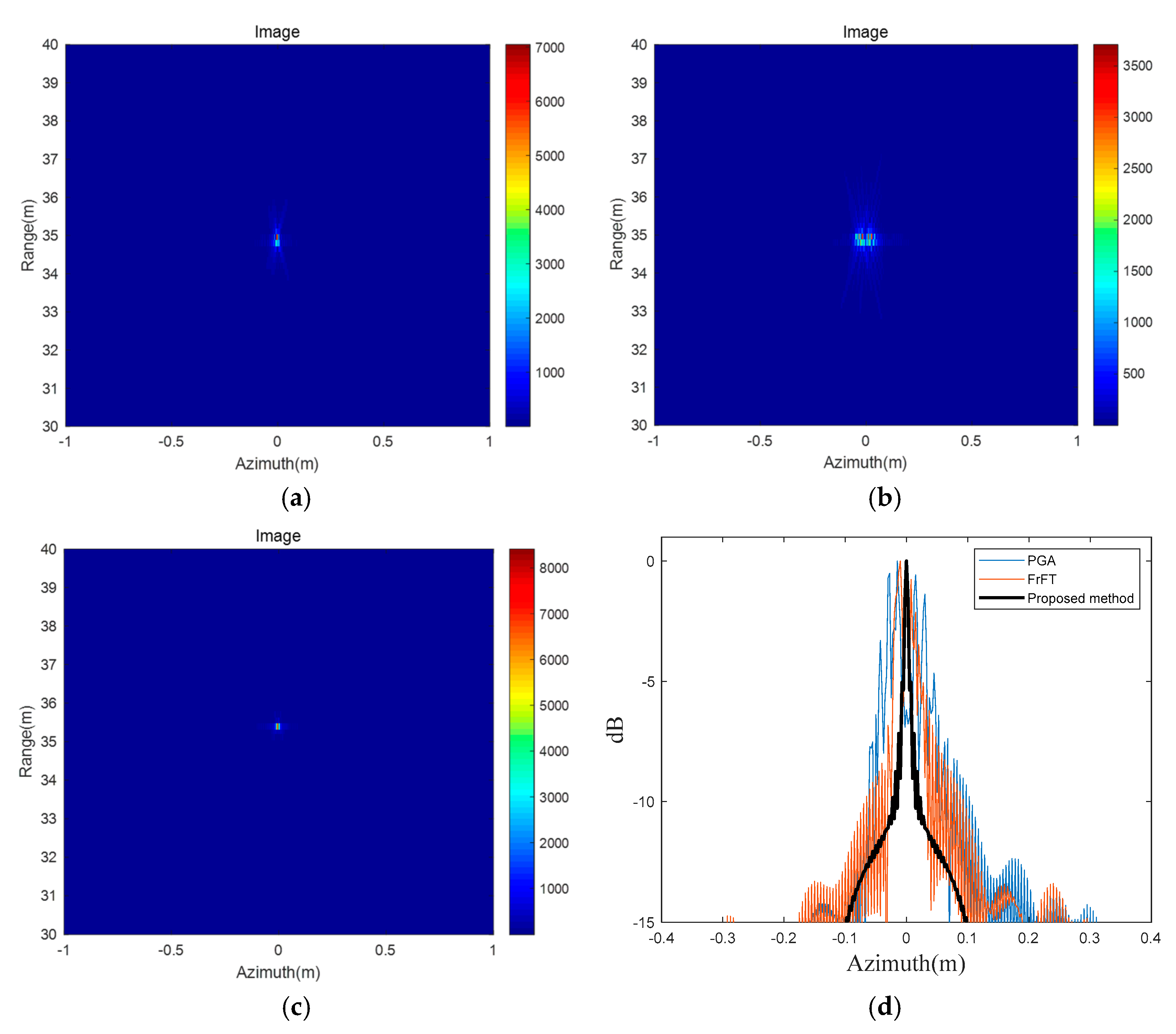
After obtaining the result of the inverse Radon transform, the components of the motion error can be estimated, and the effective compensation of the motion error can be realized. The imaging result, obtained using the proposed method, is shown in
Figure 8c. The motion error of the same target was compensated using the traditional fractional Fourier transform (FrFT) method proposed in Ref. [
15] and the phase gradient autofocus (PGA) method proposed in Ref. [
7], separately, and the results are shown in
Figure 8a,b. The PGA method utilizes the redundant Information In the defocused Image to achieve the compensation of the SAR echo phase error by estimating the phase gradient of the defocused SAR complex image. The FrFT can estimate the instantaneous chirp rate in the sliding sub-aperture and the motion error parameters can be roughly and subsequently obtained by spectral analysis and least squares regression.
Figure 8d shows the azimuthal dimension profiles of the three compensation results.
The comparison of the proposed method with other motion compensation methods is shown in
Table 3.
The PLSR and resolution of the imaging results generated by the proposed method are better than those from the traditional methods, validating the effectiveness of the proposed method.
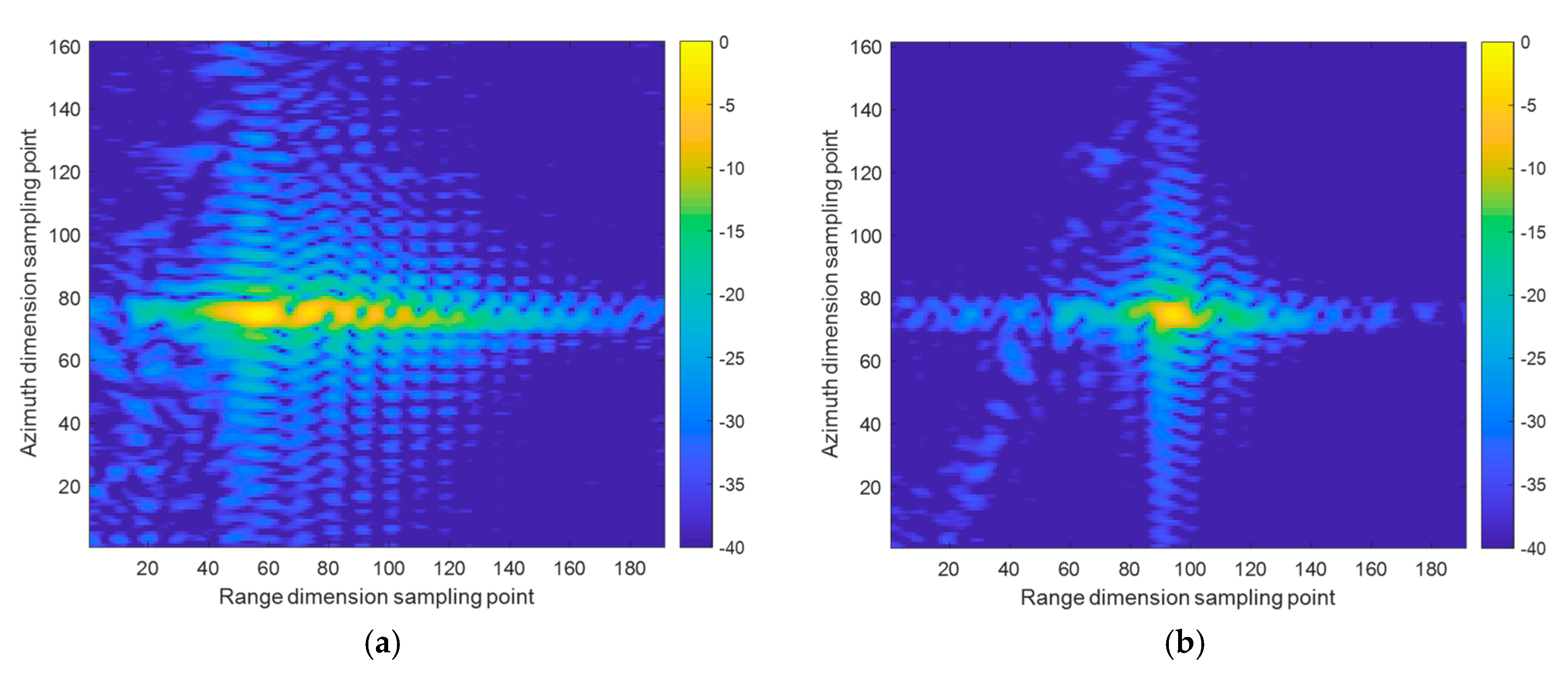
In order to verify the imaging performance of the proposed method on real targets, the angular reflector was first imaged, and its imaging result was regarded as a point target. Imaging results before and after motion error compensation are shown in
Figure 9a and 9b, respectively. It can be seen that the resolution and sharpness improved following motion error compensation.
The actual trees were then imaged using the proposed method, and the photos of the target and the experimental system are shown in
Figure 10. A radar system carried by an unmanned aerial vehicle (UAV) imaged the target at an angle of 45° from above. The UAV maintained a constant altitude and imaging angle while flying directly above the target at a constant speed. The target included the ground and several trees. The imaging parameters used in the imaging system were identical to those used during the simulations and are shown in
Table 1. The imaging results and the azimuthal dimension profile before motion compensation are shown in
Figure 11. The blue line in
Figure 11 is the normalized intensity of the target in the azimuthal dimension. It can be seen that, due to the motion error producing false targets on both sides of the real target, some overlapping shadows were visible around the actual target in the imaging result, a phenomenon which reduces imaging performance.
To compensate for the motion error and eliminate the overlapping shadows, the echo signal was processed according to the process of range migration correction and transformed as per Equation (19). Then, STFT and the inverse Radon transform were applied to the signal and the parameters of motion error estimated according to the location of the focusing point on the transformation result. Motion error compensation was accomplished by bringing the parameters into (22) and (23).
After motion error compensation of the actual target imaging results, the image result and azimuthal dimension profile were obtained and are shown in
Figure 12. The overlapping shadows around the target were effectively eliminated, creating a clearer image of the target. The parapetalons in the profile were suppressed and the main petals became more prominent. In addition, the image entropy of
Figure 12 was 4.3364 and that of
Figure 10 was 4.7273, demonstrating that
Figure 12 is clearer.


