Excess Intensity Noise in a Nonlinear Amplifying Loop-Mirror-Based Mode-Locked Laser from a Non-Reciprocal Phase Bias

Abstract
1. Introduction
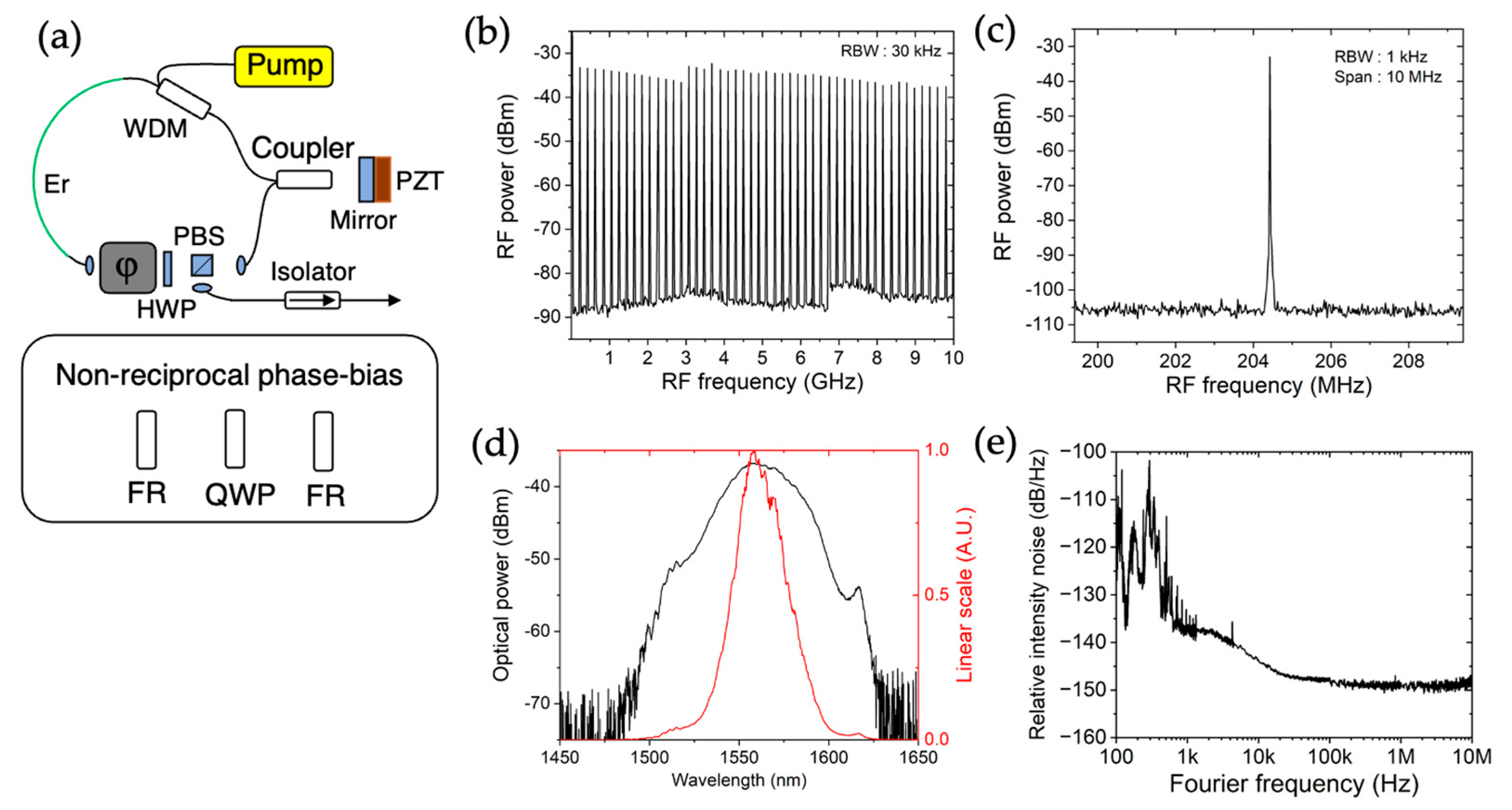
2. Methods
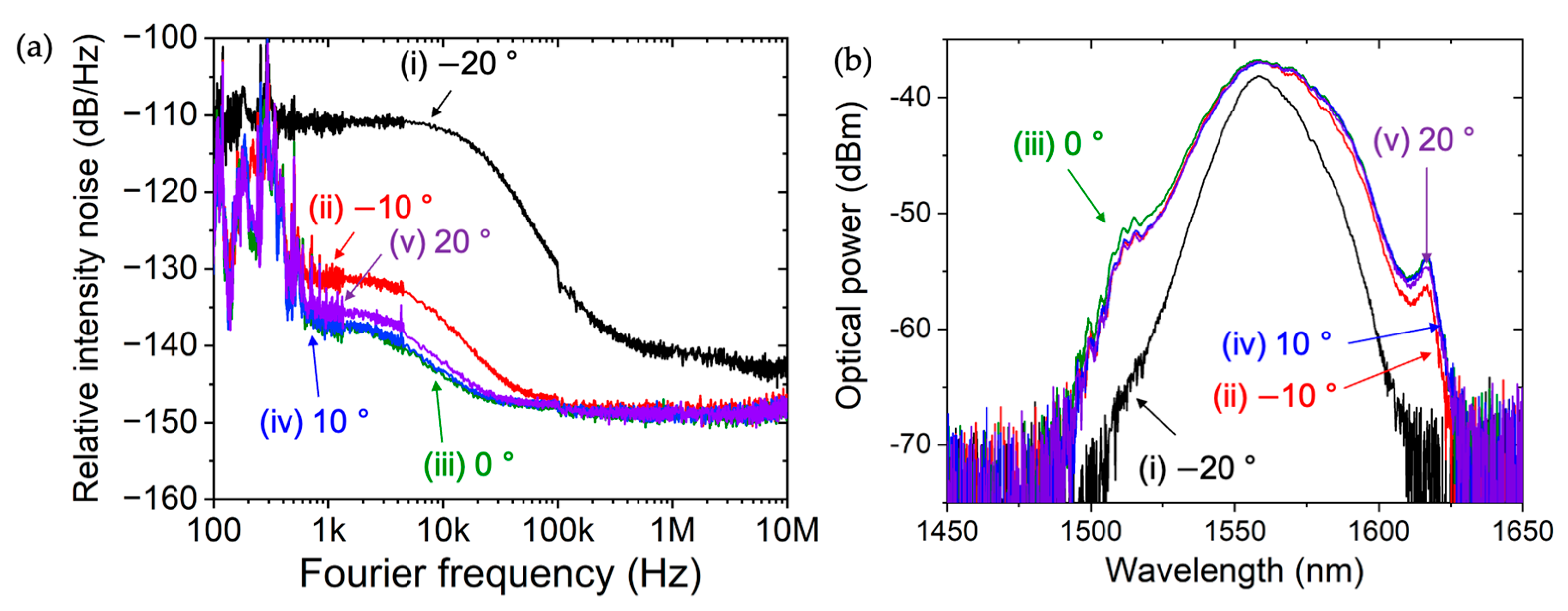
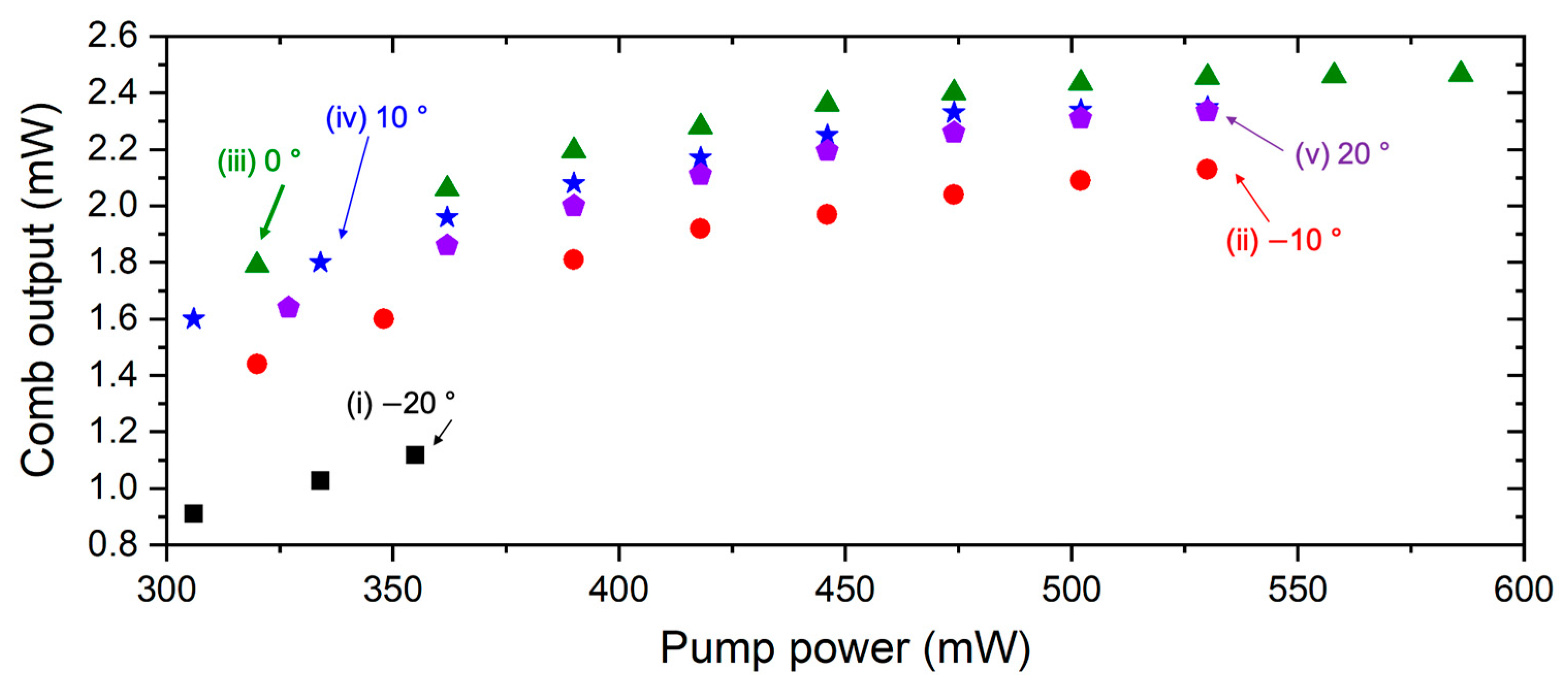
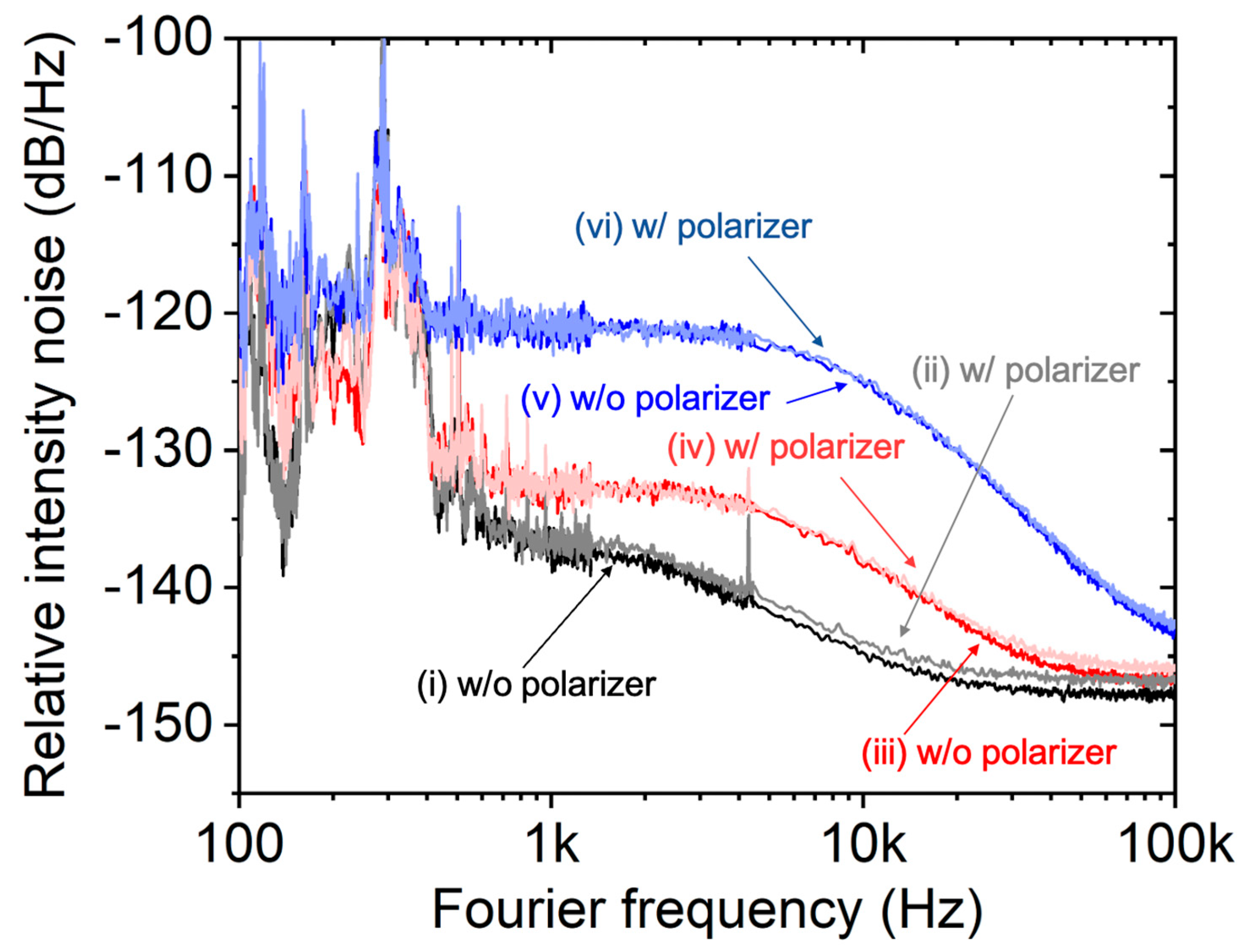
3. Results and Discussion
4. Conclusions
Funding
Institutional Review Board Statement
Informed Consent Statement
Data Availability Statement
Conflicts of Interest
References
- Hollberg, L.; Diddams, S.; Bartels, A.; Fortier, T.; Kim, K. The measurement of optical frequencies. Metrologia 2005, 42, 105–124. [Google Scholar] [CrossRef]
- Boulder Atomic Clock Optical Network (BACON) Collaboration. Frequency ratio meausrements at 18-digit accuracy using an optical clock network. Nature 2021, 591, 564–569. [Google Scholar] [CrossRef] [PubMed]
- Kim, J.; Cox, J.A.; Chen, J.; Kärtner, F.X. Drift-free femtosecond timing synchronization of remote optical and microwave sources. Nat. Photonics 2008, 2, 733–736. [Google Scholar] [CrossRef]
- Schulz, S.; Grguraš, I.; Behrens, C.; Bromberger, H.; Costello, J.T.; Czwalinna, M.K.; Felber, M.; Hoffmann, M.C.; Ilchen, M.; Liu, H.Y.; et al. Femtosecond all-optical synchronization of an X-ray free-electron laser. Nat. Commun. 2015, 6, 5938. [Google Scholar] [CrossRef] [PubMed]
- Xie, X.; Bouchand, R.; Nicolodi, D.; Guinta, M.; Hänsel, W.; Lezius, M.; Joshi, A.; Datta, S.; Alexandre, C.; Lours, M.; et al. Photonic microwave signals with zeptosecond-level absolute timing noise. Nat. Photonics 2017, 11, 44–47. [Google Scholar] [CrossRef]
- Ghelfi, P.; Laghezza, F.; Scotti, F.; Serafino, G.; Capria, A.; Pinna, S.; Onori, D.; Porzi, C.; Scaffardi, M.; Malacarne, A.; et al. A fully photonics-based coherent radar system. Nature 2014, 507, 341–345. [Google Scholar] [CrossRef] [PubMed]
- Lee, J.; Kim, Y.; Lee, K.; Lee, S.; Kim, S. Time-of-flight measurement with femtosecond light pulses. Nat. Photonics 2010, 4, 716–720. [Google Scholar] [CrossRef]
- Shi, H.; Song, Y.; Liang, F.; Xu, L.; Hu, M.; Wang, C. Effect of timing jitter on time-of-flight distance measurements using dual femtosecond lasers. Opt. Express 2015, 23, 14057–14069. [Google Scholar] [CrossRef] [PubMed]
- Ahn, C.; Na, Y.; Kim, J. Dynamic absolute distance measurement with nanometer-precision and MHz acquisition rate using a frequency comb-based combined method. Opt. Lasers Eng. 2023, 162, 107414. [Google Scholar] [CrossRef]
- Na, Y.; Kwak, H.; Ahn, C.; Lee, S.; Lee, W.; Kang, C.-S.; Lee, J.; Suh, J.; Yoo, H.; Kim, J. Massively parallel electro-optic sampling of space-encoded optical pulses for ultrafast mul-ti-dimensional imaging. Light: Sci. Appl. 2023, 12, 44. [Google Scholar] [CrossRef] [PubMed]
- Obrzud, E.; Rainer, M.; Harutyunyan, A.; Anderson, M.H.; Geiselmann, M.; Chazelas, B.; Kundermann, S.; Lecomte, S.; Cecconi, M.; Ghedina, A.; et al. A microphotonic astrocomb. Nat. Photonics 2019, 13, 31–35. [Google Scholar] [CrossRef]
- Probst, R.A.; Milaković, D.; Toledo-Padrón, B.; Lo Curto, G.; Avila, G.; Brucalassi, A.; Holzwarth, R.; Martins, B.L.C.; Esposito, M.; Grupp, F.; et al. A crucial test for astronomical spectro-graph calibration with frequency combs. Nat. Astron. 2020, 4, 603–608. [Google Scholar] [CrossRef]
- Clivati, C.; Aiello, R.; Bianco, G.; Bortolotti, C.; Natale, P.D.; Di Sarno, V.; Maddaloni, P.; Maccaferri, G.; Mura, A.; Negusini, M.; et al. Common-clock very long baseline interferometry using a coherent optical fiber link. Optica 2020, 7, 1031–1037. [Google Scholar] [CrossRef]
- Coddington, I.; Newbury, N.; Swann, W. Dual-comb spectroscopy. Optica 2016, 3, 414–426. [Google Scholar] [CrossRef] [PubMed]
- Bernhardt, B.; Ozawa, A.; Jacquet, P.; Jacquey, M.; Kobayashi, Y.; Udem, T.; Holzwarth, R.; Guelachvili, G.; Hänsch, T.W.; Picqué, N. Cavity-enhanced dual-comb spectroscopy. Nat. Photonics 2010, 4, 55–57. [Google Scholar] [CrossRef]
- Adler, F.; Thorpe, M.J.; Cossel, K.C.; Ye, J. Cavity-enhanced direct frequency comb spectroscopy: Technology and applications. Ann. Rev. Anal. Chem. 2010, 3, 175–205. [Google Scholar] [CrossRef] [PubMed]
- Lesko, D.M.; Timmers, H.; Xing, S.; Kowligy, A.; Lind, A.J.; Diddams, S.A. A six-octave optical frequency comb from a scala-ble few-cycle erbium fibre laser. Nat. Photonics 2021, 15, 281–286. [Google Scholar] [CrossRef]
- Hoghooghi, N.; Xing, S.; Chang, P.; Lesko, D.; Lind, A.; Rieker, G.; Diddams, S. Broadband 1-GHz mid-infrared frequency comb. Light Sci. Appl. 2022, 11, 264. [Google Scholar] [CrossRef] [PubMed]
- Chang, P.; Ishrak, R.; Hoghooghi, N.; Egbert, S.; Lesko, D.; Swartz, S.; Biegert, J.; Rieker, G.B.; Reddy, R.; Diddams, S.A. Mid-Infrared Hyperspectral Microscopy with Broadband 1-GHz Dual Frequency Combs. APL Photonics 2024, 9, 106111. [Google Scholar] [CrossRef]
- Kwon, D.; Kim, D. Ultralow Intensity Noise Pulse Train from an All-fiber Nonlinear Amplifying Loop Mirror-based Femtosecond Laser. Curr. Opt. Photonics 2023, 7, 708–713. [Google Scholar] [CrossRef]
Disclaimer/Publisher’s Note: The statements, opinions and data contained in all publications are solely those of the individual author(s) and contributor(s) and not of MDPI and/or the editor(s). MDPI and/or the editor(s) disclaim responsibility for any injury to people or property resulting from any ideas, methods, instructions or products referred to in the content. |
© 2024 by the author. Licensee MDPI, Basel, Switzerland. This article is an open access article distributed under the terms and conditions of the Creative Commons Attribution (CC BY) license (https://creativecommons.org/licenses/by/4.0/).
Share and Cite
Kwon, D. Excess Intensity Noise in a Nonlinear Amplifying Loop-Mirror-Based Mode-Locked Laser from a Non-Reciprocal Phase Bias. Photonics 2024, 11, 1186. https://doi.org/10.3390/photonics11121186
Kwon D. Excess Intensity Noise in a Nonlinear Amplifying Loop-Mirror-Based Mode-Locked Laser from a Non-Reciprocal Phase Bias. Photonics. 2024; 11(12):1186. https://doi.org/10.3390/photonics11121186
Chicago/Turabian StyleKwon, Dohyeon. 2024. "Excess Intensity Noise in a Nonlinear Amplifying Loop-Mirror-Based Mode-Locked Laser from a Non-Reciprocal Phase Bias" Photonics 11, no. 12: 1186. https://doi.org/10.3390/photonics11121186
APA StyleKwon, D. (2024). Excess Intensity Noise in a Nonlinear Amplifying Loop-Mirror-Based Mode-Locked Laser from a Non-Reciprocal Phase Bias. Photonics, 11(12), 1186. https://doi.org/10.3390/photonics11121186