Abstract
Nonlinear optical microscopic imaging techniques have advanced for chemically sensitive imaging of solid and liquid samples but lack advancements for gaseous samples. In this work, wide-field three-color ultrafast coherent anti-Stokes Raman scattering microscopy is implemented for selectively imaging the ambient nitrogen gas. Our technique operates by capturing a series of spectrally selected images with a rate of 5–10 frames per second. The recorded data are analyzed both qualitatively and quantitatively. This technique has been demonstrated to be sensitive to a variation of approximately 1011 nitrogen molecules in ambient air confined within a microscopic volume of 10 μm by 50 μm by 50 μm. We believe that our approach can potentially be extended toward real-time, in situ chemical imaging of the microscopic dynamics of gases, for example, in ammonia for nitrogen cycle, greenhouse gases for environmental pollution, plant fertilization regulation for precision agriculture, or byproducts produced from lower-temperature plasmas.
1. Introduction
Nitrogen is one of the amplest substances available in the atmosphere, making up 78% of the volume in ambient air in the form of N2 molecules, in addition to other nitrogen species such as nitrogen dioxide and ammonia. Nitrogen species are important because of their role in the nitrogen cycle. Microbes produce nitrogen species during the initial fixation step where ambient nitrogen molecules are converted, and later they are released into ambient air to be accessible by other organisms []. From growing crops [,,,] to optimizing fuel systems [], the sensing of nitrogen in ambient air has an incredible number of applications and can find utility virtually anywhere ambient air is located [,].
Extracting information about nitrogen species’ concentrations in ambient air has been possible, but current methods have their unique limitations. As for nitrogen species detection methods for environment pollution and precision agriculture [], there are two types of methods for checking nitrogen levels in the air: electrochemical and optical. Electrochemical sensors, such as metal-oxide semiconductors, identify gases by detecting the change in electrical signal caused by the presence of a particular gas. Typical materials required for these sensors are n-type and p-type semiconductors with electrical conductivity that changes in response to the atmospheric composition near them. Through various characterization approaches for the different types of semiconductors, information about atmospheric chemical composition can be extracted. While electrochemical sensors are valued for being inexpensive, they have limitations on gas sensing due to the semiconductor mechanisms affected in the sensors from the chemical composition of the metal oxide, humidity, high operating temperatures, and the requirement for contact sensing of the gases [,]. To date, nitrogen gas has been detected at concentrations as low as 0.01 ppm [].
Optical sensors bypass the need for semiconductor mechanism evaluation by using spectral information to extract chemical composition in gases. Optical sensing methods such as non-dispersive infrared (NDIR) sensors and satellite remote sensing can measure chemical information at the local scale and at the atmospheric scale, respectively []. NDIR sensors can sense nitrogen species by using the spectral information of compounds like ammonia, nitrous oxide, and other nitrogen oxides, which are incredibly important for various biological processes, and because they are IR active. Satellite remote sensing methods work by employing satellites equipped with imaging spectrometers that recognize solar emissions from tropospheric nitrogen dioxide, and these concentrations are then associated with nitrogen oxide concentrations on the ground level at the nearby geospatial regions []. In either case, a significant limitation of these optical techniques is that the volume of the gas being measured is very large compared to molecular scales. Another limitation of NDIR sensors is that N2 is not IR active, even though it is by far the most abundant molecule in the earth’s atmosphere.
Raman spectroscopy [] (and references therein) has been a valuable tool in chemical detection and imaging, and the modern tools derived from Raman spectroscopy have been found to be of great use in material sciences and biology. However, ordinary (spontaneous) Raman spectroscopy in its simplest design has significant limitations due to the presence of other effects such as sample fluorescence and faint Raman scattering. Coherent anti-Stokes Raman scattering (CARS) spectroscopy [,] is an important modification of ordinary Raman spectroscopy that bypasses limitations such as autofluorescence by accessing exclusively the anti-Stokes (blue-shifted) side of the laser excitation wavelength and signal power by enhancement via a coherent nonlinear optical four-wave mixing (FWM) process [,]. Pyridine gas at room temperature has been detected at concentrations as low as 30 ppm [] by using the CARS spectroscopic technique. For this reason, we chose this technique and upgraded it for chemical micro-imaging of gaseous samples.
In general, for imaging microscopy, confocal and wide-field detection configurations are typically adopted [,]. In confocal CARS microscopy [,,,], chemical micro-imaging is constructed by point-to-point scanning by the tightly focused excitation beams across the sample, which grants high spatial resolution throughout the entire area of the laser excitations’ focal spot. However, point-to-point scanning is extremely sensitive to an excitation plane to plane across the depth of the laser focal volume, and it is often time-consuming to obtain a species-specific spectral image, especially for a large sample area. Whereas wide-field imaging bypasses this by illuminating the entire focal area to excite the sample all at once instead of point-to-point scanning; however, the focal plane-to-plane sensitivity is relaxed in this case. Recently, wide-field CARS microscopy has been extensively demonstrated [,,,,,,,,]. Although current nonlinear optical microscopies have advanced for chemically sensitive imaging of solids and liquids, they have not for ambient gases.
In this work, wide-field three-color ultrafast coherent anti-Stokes Raman scattering microscopy is implemented for ambient nitrogen gas for the first time. Even with the relaxed phase-matching condition, wide-field CARS microscopy still allows for rapid imaging compared to confocal setups, especially for monitoring gases. We successfully image nitrogen gas in ambient air in real time. This work is organized as follows: The experimental setup designed for the nitrogen vibrational mode detection is explained in the next Section. Following that, the calibration and feasibility tests of the current technique are presented. The experimental results and data interpretations with detailed discussions are given in the following Section. The final Section is the conclusion.
2. Materials and Methods
To demonstrate rapid chemical microscopy imaging of nitrogen gas, we developed a unique three-color, ultrafast CARS technique. The lab environmental conditions were as follows: Considering the lab dimensions, three dehumidifiers were used to maintain the lab humidity at about 40%, and the lab temperature was maintained at the stable temperature of 70 ± 2 F. These lab conditions are necessary for the laser stabilization; however, it has a negligible impact on the sample conditions—as the study sample size is <50 μm by 50 μm. We also note that, in this technique, if measurement is impeded by dust particles, then that is to be considered as an invalid data set and the experiment can be repeated in a quick time of 0.1 s. However, in our lab conditions, no dust particles were encountered during these measurements. The power intensity–intensity correlations and fluctuations for our laser system were studied in Ref. []. As seen in Figure 1, our technique uses a broadband pump, broadband Stokes, and narrowband, slightly delayed probe beams in an all-collinear configuration, as in Ref. []. The pump and Stokes beams are purposely tuned to be resonant to the vibrational mode of nitrogen molecules. Thus, the vibrational modes for the other gases in the ambient air are off-resonant to the tuned beams and their responses are negligible as compared to the nitrogen CARS signal. In Ref. [], we studied how to distinguish resonant from non-resonant nonlinear optical processes. The pump and Stokes beams prepare the nitrogen molecules to vibrate in phase. At a certain delay [,], the narrowband probe beam arrives and is scattered off from these synchronized molecules to produce a coherently brightened anti-Stokes Raman signal with a narrow spectral peak as close as possible to that of the probe. An ytterbium-doped amplified megahertz (MHz) femtosecond (fs) laser system (MXR-Clark) with 10 μJ energy per pulse is used in our setup. The details are given elsewhere [,]. The laser output 1035 nm beam (ca. 200 fs) is passed through a non-collinear optical parametric amplifier (NOPA) to produce a tunable NOPA beam in the region of 650 nm to 950 nm in addition to the second harmonics at 520 nm. The residual 1035 nm stands for the Stokes beam and the tunable NOPA beam stands for the pump beam. The pump beam is tuned to ca. 830 nm. Thus, the pump (ca. 30 fs, 50 nm broad at center 830 nm) and Stokes (at 1035 nm) beams are on-resonance to the vibrational mode of nitrogen molecules at ca. 2330 cm−1 []. The pump beam is then directed through a computer-controlled delay stage for temporal control. The 520 nm beam is passed through the homemade pulse shaper to become a narrowband probe beam of about 10 cm−1 []. The arrival time of the probe pulse is controlled by the second delay stage, see the top part in Figure 1. The three beams are recombined with special dichromatic mirrors and then focused with a 100 mm (focal length) achromatic lens in the ambient air at room temperature. The laser focal region after is about 45 μm in diameter. It is estimated that approximately 1011 nitrogen molecules in ambient air are within the beam focus as a microscopic volume of approximately 10 μm by 50 μm by 50 μm. The calculation is performed by using the density of nitrogen in ambient air at 70 F and 40% humidity, integrating it over the given volume, and determining the approximate number of molecules from the number of moles of N2 molecules in that region. This measurement was performed at an approximate nitrogen gas concentration of 78% or 780,000 ppm. For comparison, pyridine molecules in gas phase at a concentration of 30 ppm and room temperature were observed by using the CARS spectroscopy technique without microscopic imaging capability in our earlier work []. The powers of the probe, pump, and Stokes beams were 7, 33, and 135 mW, respectively. The pump and Stokes pulses arrived simultaneously, and the probe was delayed by ca. 1.3 ps to avoid an FWM background [,].
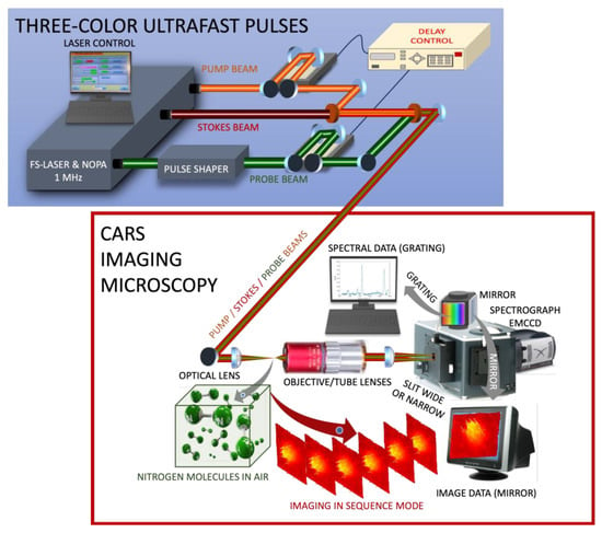
Figure 1.
(Color online) A schematic of the wide-field three-color ultrafast imaging CARS microscopy. (Top) Three beams are produced by the fs laser combined with the NOPA. Timing of the probe at 520 nm (green) and pump at 830 nm (orange) is adjusted by two delay stages. The Stokes beam (maroon) is a residual of 1035 nm laser beam. (Bottom) All three beams are combined by using the two dichromatic mirrors and focused by the optical lens in the air. The CARS signal is collected by the long working distance objective lens by using shortpass and bandpass filters. Combined with its compatible tube lens, they form an image that is magnified 100 times. Data are recorded using a spectrograph with imaging EMCCD. When a grating is used, and the entrance slit is closed, the spectral data are recorded. While the slit is wide open and the mirror is in place, image data are captured. Images are saved either in a single file in accumulation mode, that is, accumulated (added) up all the images, or are saved in separate files in kinetic mode.
In the bottom part of Figure 1, the layout of the CARS imaging microscope is shown. For microscopic imaging, a 50×, infinity corrected, long working distance (4 mm) objective lens (Mitutoyo, NA = 0.65) was used. The resolution power of this objective lens is about 0.7 μm. Together with the compatible tube lens of 200 mm focal length, the present system forms 100× magnified images at the sensor of the imaging electron-multiplying charge-coupled device (EMCCD, iXon, Andor, Abingdon, UK) through the spectrograph (Kymera, Andor, Abingdon, UK). Specific shortpass and bandpass filters (Semrock, Thorlabs, New Jersey, United States) are used to isolate the CARS signal in the UV region. The spectrograph was allowed to switch its grating to a flat mirror to capture images. The slit of the spectrograph can be wide open to 15 mm. Using a USAF-1951 resolution test chart (Edmund Optics, Barrington, IL, USA), our imaging microscope system was calibrated [].
It demonstrates that a linear size per pixel corresponds to 0.75 μm. For example, the length of the imaged wide-open slit at the entrance is about 200 pixels, which is consistently converted to 15 mm. Therefore, for illustrating images, if the numbers of pixels were used, then the actual dimensions were converted using a scaling parameter of 0.75 μm per pixel. While images were captured by using the mirror, spectral data were recorded by using the grating (600 grooves per mm) inside the spectrograph and simply pushing a button in the software provided by Andor. Furthermore, the system was capable of taking images in two modes. In the accumulation mode, multiple data were recorded with a short exposure time and were added up to a single data file. While in kinetic mode, multiple image data were captured and saved separately. Figure 2 demonstrates that nitrogen gas is indeed selectively monitored among other species present in the air. First, raw spectral data are recorded as a result of 100 accumulations of 0.2 s exposure time per frame when all three beams are present (peaked curve in black) and again when the pump and Stokes beams are blocked (flat background in red) in Figure 2A. All measurements except for spectral data shown in Figure 2A are taken at the open slit. A single, strong peak stands out, which corresponds to an anti-Stokes Raman (blue shifted) signal at −2330 cm−1 for the Raman active vibrational mode for N2. The background subtracted spectrum (blue) is given in (Figure 2B). Wide-field microscopic image data as a result of 100 accumulations of 0.2 s exposure time per frame in three cases: when (Figure 2C) all beams are blocked except for the probe beam; (Figure 2D) only the probe beam is blocked; and, finally, (Figure 2E) all beams are present. The images are cropped down to 150 μm by 150 μm. Unless all beams are present, images are featureless and flat. In this case, we observed a wide-field CARS signal that forms an image in the center with a full width at half maxima (FWHM) of ca 45 μm. This is about the focal size of all three beams after the achromatic lens with a 100 mm focal length. In this region, the third-order nonlinear optical processes occur giving a selective chemical signature of nitrogen gas among other substances in the ambient air. The CARS image in Figure 2E is captured after accumulating over 100 frames.

Figure 2.
(Color online) (A) The raw spectral data. The peak corresponds to an anti-Stokes Raman shift at −2330 cm−1 for the N2 Raman active vibrational mode. (B) The background subtracted the spectrum. (C) The image resulting from 100 accumulations of 0.2 s exposure time per frame when the pump and Stokes beams are blocked and only the probe beam is present, and (D) when the probe beam is blocked and the other two are present. (E) All three beams are present. Image size is 150 μm by 150 μm.
The present technique used a 10 cm optical lens. In principle, it can be extended to a stand-off configuration that uses a lens of greater than 1 m focal length; however, the laser must be focused tightly to initiate the nonlinear optical processes. This is one of the significant limitations of the technique to be scaled to a larger volume. This microscopic imaging technique is best applied for chemical sensing at the microscopic scale; however, the small volume is under ambient conditions, and it does not necessarily need to be under controlled conditions.
3. Feasibility Test of the Current Technique
Data accumulation is time-consuming; therefore, the question arises whether it is feasible to perform rapid monitoring of nitrogen gas in real time. We performed calibration tests for the device’s dark current as varying EM (electron multiplication) gain and exposure time. The data for background versus EM gain exhibit a linear monotonic relationship with a slope of 0.8. Furthermore, for calibration of the CARS signal, the liquid benzene sample is used. The CARS signal at the benzene ring breathing mode is linearly increased as a function of EM gain with a slope of 143. For this reason, all data presented in this work are recorded with an EM gain of 200. In this case, the background increases from 480 to 650, while the CARS signal increases from 500 up to 30,000. In our current technique, the signal-to-noise ratio is improved by approximately 45 times. This makes real-time monitoring with as low as 0.1 s exposure feasible. The data for background versus exposure exhibit a constant plateau, whereas the CARS signal increases linearly for short interaction times. This suggests that the scan with 0.2 s exposure is better than that with 0.1 s exposure. Finally, we calibrated the CARS signal (for liquid benzene) recorded in kinetic mode with 0.2 s exposure time. Without EM gain and with 200 EM gain, the standard deviations are approximately 13% and below 10%, respectively. Based on these calibration tests, image frames recorded with as low as 0.1 s exposure time can, indeed, form a distinct CARS image. In Figure 3, single frames (again 150 μm by 150 μm in size) for a duration of 0.1 s exposure are captured: when (Figure 3A) all beams are blocked; (Figure 3B) the pump and Stokes beams are blocked; (Figure 3C) pump is blocked; (Figure 3D) the probe is blocked; (Figure 3E) all beams are present creating an image due to CARS signal; and finally (Figure 3F) the CARS image is denoised with the help of the standard MATLAB code that uses a Bayesian method. Thus, when any one of the three beams is blocked, the CARS signal disappears leaving behind a featureless and flat background. Only if all three beams are present will the CARS signal form a distinctly structured image standing alone within the focal area of the input beams. These individual CARS images are recorded in kinetic mode and each image data will be analyzed frame by frame in the next Section.

Figure 3.
(Color online) Individual images are captured with an exposure time of 0.1 s without any accumulation: (A) All beams are blocked. (B) The pump and Stokes are blocked, but the probe is present. (C) The pump beam is blocked and the other two are present. (D) The probe is blocked, but the other two are present. (E) All three beams are present. (F) The image in (E) is denoised using an empirical Bayesian method. Image size is 150 μm by 150 μm.
4. Results and Discussion
The main objective of this work is to demonstrate the rapid monitoring of nitrogen gas in ambient air on a microscopic scale. To achieve this objective, we need both qualitative (i.e., by a color-coded visual inspection) and quantitative data analyses to distinguish the nitrogen signal over the fluctuating background. Overall, we performed six complete scans each, including 99 separate images (the first frame from the original 100 frames in each scan is discarded) in kinetic mode with an exposure time of either 0.1 s or 0.2 s and with or without missing input beams. Figure 4, Figure 5 and Figure 6 illustrate the mosaics montaged from 99 frames (tiles). The frames are separated by white lines. The raw recorded data are converted to grayscale images by using MATLAB (mat2gray). The color scale is shown in each mosaic image. Each frame in the mosaic is numbered accordingly. For example, the first row shows a total of 11 frames from the first frame numbered 1 to frame 11. The next row starts from frame 12 to frame 22, and so on. The last (ninth) row contains frames from 89 to 99. In Figure 4 and Figure 5 (see, left), the mosaics for scans 1, 2, and 3 are displayed, where 0.2 s exposure time is used, and all three beams are present. In Figure 5 (see, right) and Figure 6, the mosaics for scans 4, 5, and 6 are displayed, where 0.1 s exposure time is used, and all three beams are present except for the last figure for scan 6. In scan 6, again, we test the background when the pump and Stokes beams are blocked, but the probe beam is present.
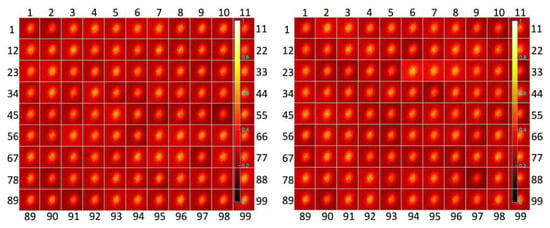
Figure 4.
(Color online) Mosaics montaged with 99 frames (Grayscale images converted from raw data): (Left) Scan 1. All three beams are present with 0.2 s exposure. (Right) Scan 2. All three beams are present with 0.2 s exposure. Image size of each frame is 113 μm by 113 μm. Frames are separated by white lines. The color scale is the same for all scans in each sequence of 99 frames.
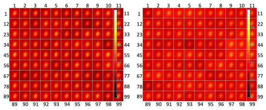
Figure 5.
(Color online) Mosaics montaged with 99 frames (Grayscale images converted from raw data): (Left) Scan 3. All three beams are present with 0.2 s exposure. (Right) Scan 4. All three beams are present with 0.1 s exposure. Image size of each frame is 113 μm by 113 μm. Frames are separated by white lines. The color scale is the same for all scans in each sequence of 99 frames.
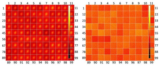
Figure 6.
(Color online) Mosaics montaged with 99 frames (Grayscale images converted from raw data): (Left) Scan 5. All three beams are present with 0.1 s exposure. (Right) Scan 6. Only the probe beam is present with 0.1 s exposure. Image size of each frame is 113 μm by 113 μm. Frames are separated by white lines.
Next, the recorded raw image data are analyzed and compared quantitatively. In Figure 7A–F, the mean image for each scan is displayed after averaging over 99 raw data frames recorded in kinetic mode. The CARS signals form an image with an FWHM of ca. 45 μm in Figure 7A–E. This width is consistent with the data for 100 accumulations in Figure 2E. Again, the flat background is shown after averaging over 99 frames, for only the probe beam is present in Figure 7F.

Figure 7.
(Color online) Mean images after averaging overall 99 raw data frames: Images (A), (B), (C), (D), (E), and (F) correspond to scans 1, 2, 3, 4, 5, and 6, respectively. (G) A histogram of average counts for these six scans. Image size is 150 μm by 150 μm.
Average counts and the standard deviations for each scan over 150 μm by 150 μm area are obtained in Figure 7G. A histogram illustrates the average count per scan (colored bars) with the standard deviations (error bars). The first three data (blue bars) correspond to scans 1, 2, and 3 where the exposure time is 0.2 s, the next data (red bars) represent scans 4 and 5 with the exposure time of 0.1 s, and the last data (the black bar) are scan 6 for the background with the two beams being blocked. They are 249 ± 5.1 (scan 1), 246 ± 7.6 (scan 2), 235 ± 5.7 (scan 3), 120 ± 3.6 (scan 4), 116 ± 3.2 (scan 5), and 0 ± 2.1 (scan 6), where an average count for scan 6, i.e., the background of 494, is subtracted from all others. As we expected, the average counts for the scans with 0.1 s exposure time are approximately doubled for those scans with 0.2 s exposure time. The standard deviations are also classified into three different groups as expected.
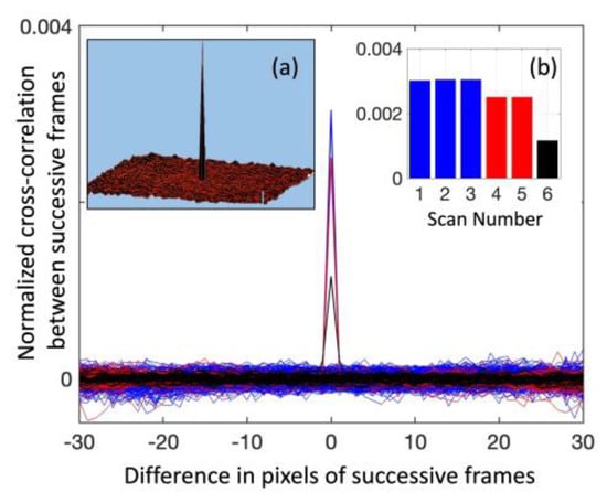
For the background, even though the probe beam is present, the standard deviations are the lowest. Data are stored on a standard personal computer with regular operating speed. Timestamps for saved files indicate that in less than 160 s, all 99 separate data are saved on the hard disc at a rate as fast as 1.6 s, regardless of the interaction times being 0.1 s or 0.2 s. The total duration of each scan is thus 160 s, e.g., the 2nd and 20th frames correspond to 3.2 s and 32 s, respectively. In Figure 8, the noise fluctuations are displayed as functions of the number of frames. These numbers are converted into timestamps. The noise fluctuations are calculated as the standard deviations in a percentage with respect to the above-mentioned average counts with an offset of 494. As is seen, the changes in the concentration of nitrogen gas greater than the noise limit of 10% can be monitored unambiguously by the current technique for both 0.1 s and 0.2 s integration times. This noise limit of 10% is consistent with our calibration in the previous Section. Furthermore, we adopt the q-score test as the heterogeneity measure for mosaic images [,,] and the normalized two-dimensional cross-correlation calculations between the successive frames as the image similarity measure using the standard MATLAB codes (see Figure 9a,b). These additional measures quantitatively distinguish CARS signals from the background. For example, q-scores for the patterns formed by CARS signals are 0.003, 0.007, 0.004, 0.004, and 0.003 for scans 1, 2, 3, 4, and 5, respectively, and are, on average, four times greater than the q-score for the background, which is 0.0008 for scan 6. The image similarity measures are greater for scans with a 0.2 s exposure than those for scans with a 0.1 s exposure, but they measure lowest for the background, as seen in Figure 9b.
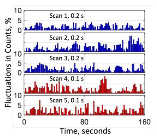
Figure 8.
(Color online) The noise fluctuations in counts as percentages for the average counts from Figure 7G.
5. Conclusions
A wide-field microscopy imaging technique is presented here for the first time for ambient gases. Current nonlinear optical (including CARS) microscopies are not feasible for gas samples, in particular ambient gases. The presented wide-field CARS microscopic configuration in this work is an important improvement for rapid micro-imaging for gaseous samples. The technique is capable of monitoring an average of 1011 nitrogen molecules with <10% standard deviations in the brief duration of the laser exposure as fast as 0.1 s, within a microscopic volume of 10 μm by 50 μm by 50 μm. It operates by capturing a series of spectrally selected images of nitrogen gas in ambient air with a rate of 5–10 frames per second at up to 1024 by 1024 pixels. Our fs laser source is not powerful enough to initiate nonlinear optical processes within extended volume. This is one of the limitations of this technique when scaling to a larger volume. This microscopic imaging technique is best applied for chemical imaging at the microscopic scale; however, the small volume is under ambient conditions, and it does not necessarily need to be under controlled conditions. We believe that our approach has the potential to be extended to high-resolution spatiotemporal species-specific imaging of the dynamical changes within a microscopic volume, e.g., in ammonia for nitrogen cycle, greenhouse gases for environmental pollution, plant fertilization regulation for precision agriculture, or byproducts produced from lower-temperature plasmas in situ.
Author Contributions
Conceptualization, G.O.A.; methodology, G.O.A.; validation, G.O.A. and B.S.; formal analysis, G.O.A. and L.C.; investigation, G.O.A., B.S. and L.C.; data curation, G.O.A.; writing—original draft preparation, G.O.A., B.S., T.N.B. and L.C.; writing—review and editing, G.O.A., B.S., T.N.B. and L.C.; visualization, G.O.A.; supervision, G.O.A.; project administration, G.O.A. and T.N.B. All authors have read and agreed to the published version of the manuscript.
Funding
G.O.A. would like to acknowledge the support from the USCRP (Award No: W912HZ-22-2-0017). T.N.B. and B.S. would like to acknowledge the gracious support of funding from the College of Arts and Sciences, University of Alabama, as T.N.B.’s startup grant, and B.S.’s postdoctoral fellowship from the College of A&S.
Data Availability Statement
Partial data are available upon request.
Acknowledgments
G.O.A. thanks to Chuji Wang for the stimulating discussions.
Conflicts of Interest
The authors declare no conflicts of interest.
References
- Robertson, G.P.; Groffman, P.M. Nitrogen transformations. In Soil Microbiology, Ecology and Biochemistry, 5th ed.; Paul, E.A., Frey, S.D., Eds.; Elsevier: Amsterdam, The Netherlands, 2024; Volume 14, pp. 407–438. [Google Scholar]
- Fowler, D.; Coyle, M.; Skiba, U.; Sutton, M.A.; Cape, J.N.; Reis, S.; Sheppard, L.J.; Jenkins, A.; Grizzetti, B.; Galloway, J.N.; et al. The Global Nitrogen Cycle in the Twenty-First Century. Philos. Trans. R. Soc. B Biol. Sci. 2013, 368, 20130164. [Google Scholar]
- Takai, K. The Nitrogen Cycle: A Large, Fast, and Mystifying Cycle. Microbes Environ. 2019, 34, 223–225. [Google Scholar] [CrossRef] [PubMed]
- Robertson, G.P.; Vitousek, P.M. Nitrogen in Agriculture: Balancing the Cost of an Essential Resource. Annu. Rev. Environ. Resour. 2009, 34, 97–125. [Google Scholar] [CrossRef]
- Udvardi, M.; Below, F.E.; Castellano, M.J.; Eagle, A.J.; Giller, K.E.; Ladha, K.J.; Liu, X.; Maaz, T.M.; Nova-Franco, B.; Raghuram, N.; et al. A Research Road Map for Responsible Use of Agricultural Nitrogen. Fron. Sustain. Food Syst. 2021, 5, 660155. [Google Scholar] [CrossRef]
- Burns, M.; Cavage, W.M. Inerting of a Vented Aircraft Fuel Tank Test Article with Nitrogen-Enriched Air; National Technical Information Service (NTIS): Springfield, VA, USA, 2001. [Google Scholar]
- Yousuf, M.F.; Mahmud, M.S. Review on Detection Methods of Nitrogen Species in Air, Soil and Water. Nitrogen 2022, 3, 101–117. [Google Scholar]
- Zhang, X.; Davidson, E.; Mauzerall, D.; Searchinger, T.D.; Dumas, P.; Shen, Y. Managing Nitrogen for Sustainable Development. Nature 2015, 528, 51–59. [Google Scholar] [CrossRef]
- Wang, C.; Yin, L.; Zhang, L.; Xiang, D.; Gao, R. Metal oxide gas sensors: Sensitivity and influencing factors. Sensors 2010, 10, 2088–2106. [Google Scholar]
- Ali, M.; Ali, S.; Mallick, S.; Bhandari, S.; Ali, M.; Hazra, S.; Roy, B.; Chattopadhyay, S.; Karmakar, S.; Chattopadhyay, D. Dual parameter smart sensor for nitrogen and temperature sensing based on defect-engineered 1T-MoS2. Sci. Rep. 2024, 14, 21469. [Google Scholar] [CrossRef]
- McDonagh, C.; Burke, C.S.; MacCraith, B.D. Optical Chemical Sensors. Chem. Rev. 2008, 108, 400–422. [Google Scholar] [CrossRef]
- Kiefer, J.; Seeger, T.; Steuer, S.; Schorsch, S.; Weikl, M.C.; Leipertz, A. Design and characterization of a Raman scattering- based sensor system for temporally resolved gas analysis and its application in a gas turbine power plant. Meas. Sci. Technol. 2008, 19, 085408. [Google Scholar] [CrossRef]
- Maker, P.D.; Terhune, R.W. Study of Optical Effects Due to an Induced Polarization Third Order in the Electric Field Strength. Phys. Rev. 1965, 137, 801–818. [Google Scholar] [CrossRef]
- Pestov, D.; Murawski, R.K.; Ariunbold, G.O.; Wang, X.; Zhi, M.; Sokolov, A.V.; Sautenkov, V.A.; Rostovtsev, Y.V.; Dogariu, A.; Huang, Y.; et al. Optimizing the laser-pulse configuration for coherent Raman spectroscopy. Science 2007, 316, 265–268. [Google Scholar] [CrossRef] [PubMed]
- Pestov, D.; Ariunbold, G.O.; Wang, X.; Murawski, R.K.; Sautenkov, V.A.; Sokolov, A.V.; Scully, M.O. Coherent versus incoherent Raman scattering: Molecular coherence excitation and measurement. Opt. Lett. 2007, 32, 1725–1727. [Google Scholar] [CrossRef] [PubMed]
- Altangerel, N.; Ariunbold, G.O.; Yi, Z.; Begzjav, T.; Ocola, E.; Laane, J.; Scully, M.O. Coherent stokes Raman spectroscopy of pyridine in gas-phase at low temperature. Proceedings of Conference on Lasers and Electro-Optics, San Jose, CA, USA, 5–10 June 2016. [Google Scholar]
- Dieing, T.; Hollricher, O.; Toporski, J. Confocal Raman Microscopy; Springer: New York, NY, USA, 2011. [Google Scholar]
- Richardson, J.H. Handbook for the Light Microscope; Noyes Publications: Park Ridge, NJ, USA, 1991. [Google Scholar]
- Duncan, M.D.; Reintjes, J.; Manuccia, T.J. Scanning coherent anti-Stokes Raman microscopy. Opt. Lett. 1982, 7, 350–352. [Google Scholar] [CrossRef]
- Cheng, J.X.; Xie, X.S. Coherent Raman Scattering Microscopy; CRC Press: Boca Raton, FL, USA, 2012. [Google Scholar]
- Camp, C.H., Jr.; Lee, Y.J.; Heddleston, J.M.; Hartshorn, C.M.; Walker, A.R.H.; Rich, J.N.; Lathia, J.D.; Cicerone, M.T. High-speed coherent Raman fingerprint imaging of biological tissues. Nat. Photonics 2014, 8, 627–634. [Google Scholar] [CrossRef]
- Saar, B.G.; Freudiger, C.W.; Reichman, J.; Stanley, C.M.; Holtom, G.R.; Xie, X.S. Video-Rate Molecular Imaging in Vivo with Stimulated Raman Scattering. Science 2010, 330, 1368–1370. [Google Scholar] [CrossRef] [PubMed]
- Duarte, A.S.; Schnedermann, C.; Kukura, P. Wide-Field Detected Fourier Transform CARS Microscopy. Sci. Rep. 2016, 6, 37516. [Google Scholar] [CrossRef]
- Silve, A.; Dorval, N.; Schmid, T.; Mir, L.M.; Attal-Tretout, B. A Wide-Field Arrangement for Single-Shot CARS Imaging of Living Cells. J. Raman Spectrosc. 2012, 43, 644–650. [Google Scholar] [CrossRef]
- Lei, M.; Winterhalder, M.; Selm, R.; Zumbusch, A. Video-Rate Wide-Field Coherent Anti-Stokes Raman Scattering Microscopy with Collinear Nonphase-Matching Illumination. J. Biomed. Opt. 2011, 16, 021102. [Google Scholar] [CrossRef][Green Version]
- Shen, Y.; Wang, J.; Wang, K.; Sokolov, A.V.; Scully, M.O. Wide-Field Coherent Anti-Stokes Raman Scattering Microscopy based on Picosecond Supercontinuum Source. APL Photonics 2018, 3, 116104. [Google Scholar] [CrossRef]
- Heinrich, C.; Bernet, S.; Ritsch-Marte, M. Wide-field coherent anti-Stokes Raman scattering microscopy. Appl. Phys. Lett. 2004, 84, 816–818. [Google Scholar] [CrossRef]
- Heinrich, C.; Hofer, A.; Ritsch, A.; Ciardi, C.; Bernet, S.; Ritsch-Marte, M. Selective imaging of saturated and unsaturated lipids by wide-field CARS microscopy. Opt. Express 2016, 16, 2699–2708. [Google Scholar] [CrossRef] [PubMed]
- Toytman, I.; Cohn, K.; Smith, T.; Simanovskii, D.; Palanker, D. Wide-field coherent anti-Stokes Raman scattering microscopy with non-phase-matching illumination. Opt. Lett. 2007, 32, 1941–1943. [Google Scholar]
- Toytman, I.; Simanovskii, D.; Palanker, D. On illumination schemes for wide-field CARS microscopy. Opt. Express 2009, 17, 7339–7347. [Google Scholar] [CrossRef] [PubMed]
- Evans, C.L.; Potma, E.O.; Puoris’haag, M.; Cote, D.; Lin, C.P.; Xie, X.S. Chemical imaging of tissue in vivo with video-rate coherent anti-Stokes Raman scattering microscopy. Proc. Natl. Acad. Sci. USA 2005, 102, 16807–16812. [Google Scholar] [CrossRef]
- Nagpal, S.; Semon, B.; Ariunbold, G.O. Distinguishing Resonant from Non-Resonant Nonlinear Optical Processes Using Intensity–Intensity Correlation Analyses. Appl. Spectrosc. 2021, 75, 1382–1390. [Google Scholar] [CrossRef]
- Ariunbold, G.O.; Nagpal, S.; Semon, B. Quantitative time-resolved buildup in three-color coherent anti-Stokes Raman scattering. Spectrosc. Lett. 2020, 53, 383–390. [Google Scholar] [CrossRef]
- Semon, B.; Jaffe, M.; Wang, H.; Priddy, L.B.; Ariunbold, G.O. Analysis of osteoporotic tissue using combination nonlinear optical imaging. Opt. Commun. 2024, 554, 130160. [Google Scholar] [CrossRef]
- Wang, J.-F.; Zhang, T.-L.; Fu, B.-J. A measure of spatial stratified heterogeneity. Ecol. Indic. 2016, 67, 250–256. [Google Scholar] [CrossRef]
- Tchapga, C.T.; Mih, T.A.; Kouanou, A.T.; Fonzin, T.F.; Fogang, P.K.; Mezatio, B.A.; Tchiotsop, D. Biomedical Image Classification in a Big Data Architecture Using Machine Learning Algorithms. J. Healthc. Eng. 2021, 2021, 9998819. [Google Scholar] [CrossRef]
Disclaimer/Publisher’s Note: The statements, opinions and data contained in all publications are solely those of the individual author(s) and contributor(s) and not of MDPI and/or the editor(s). MDPI and/or the editor(s) disclaim responsibility for any injury to people or property resulting from any ideas, methods, instructions or products referred to in the content. |
© 2024 by the authors. Licensee MDPI, Basel, Switzerland. This article is an open access article distributed under the terms and conditions of the Creative Commons Attribution (CC BY) license (https://creativecommons.org/licenses/by/4.0/).
