Abstract
Optical phased arrays (OPAs) have great potential in the fields of integrated solid-state light detection and ranging. The ranging distance of an OPA can be further enlarged by improving the directionality of the grating antenna. A high-directionality silicon nitride grating antenna with a distributed Bragg reflector (DBR) is proposed. The DBR consists of a stack of silicon nitride and silicon dioxide layers, which are utilized as the bottom reflectors to further reduce downward radiation. In a simulation, the directionality of the antenna exceeded 71.6% within the wavelength range of 1420–1740 nm. Additionally, the directionality of the antenna can achieve 97.6% at 1550 nm. Compared to a grating antenna without a DBR, the directionality is improved by 1.52 dB. Moreover, the proposed silicon nitride grating antenna has a large fabrication tolerance and is compatible with CMOS fabrication techniques, showing great potential for enhancing the performance of the integrated optical phased array.
1. Introduction
The integrated optical phased array (OPA) which uses silicon photonic technology has attracted tremendous attention as a non-mechanical beam steering device due to its high level of integration and compatibility with CMOS technology [1,2,3]. It has been widely used in various applications that require precise beam steering and high directionality, including light detection and ranging (LiDAR) [4,5], optical communication [6], imaging [7,8], and biosensors [9]. The grating antenna is one of the key components of the integrated OPA which can convert the light in the waveguide to free-propagating optical radiation and vice versa [10]. Normally, the maximum ranging distance of an OPA is directly determined by the output power of the grating antenna [11,12,13]. However, the silicon-based grating antenna cannot sustain a very high input optical power due to its nature of two-photon absorption and free carrier absorption [14], which limits its capability in handling high-power signals. In contrast, silicon nitride exhibits high-power-handling capabilities with low nonlinear absorption and low-loss-propagating properties in a broad wavelength range [15,16], making it a promising alternative material to enhance the performance of the grating antenna.
Moreover, the output power can be further enhanced by fully using the input optical power, i.e., by improving the directionality of the grating antenna. The directionality is defined as the ratio of upward light power to the total out optical power; however, there is an unavoidable downward radiation of power to the substrate, resulting in poor directionality. To solve this problem, various approaches have been proposed. The maximum upward directionality of the antenna can reach over 90% through the use of a dual-level or three-layer grating antenna to suppress the bidirectional radiation, but the fabrication complexity is significantly increased [13,17]. The other approach is to use bottom reflectors such as metal mirrors or bottom gratings to block the downward radiation [18,19]. However, these traditional reflectors are fragile at high temperatures, and the fabrication process is relatively complex and incompatible with CMOS fabrication.
In this paper, a high-directionality silicon nitride grating antenna is proposed which consists of a silicon nitride grating with a low nonlinear effect and large damage threshold and a bottom reflector. The DBR is composed of a stack of silicon nitride, and silicon dioxide is used as the bottom reflector to reduce the downward radiation. The upward directionality can be improved to 97.6% at a wavelength of 1550 nm, offering a promising means of increasing the output power of the integrated optical antenna, with great potential for the integrated OPA.
2. Structure and Principle
A three-dimensional (3D) schematic of the silicon nitride antenna is shown in Figure 1a. It consists of the total thickness of the silicon nitride Htotal = 400 nm and a distributed Bragg reflector (DBR). A cross-section of the silicon nitride antenna is illustrated in Figure 1b, where a DBR consisting of a multilayer stack is deposited on the silicon substrate, and a shallow etched silicon nitride grating is placed on the buried oxide (BOX) layer (HBOX). Additionally, a silicon dioxide cladding layer is deposited to protect the device.
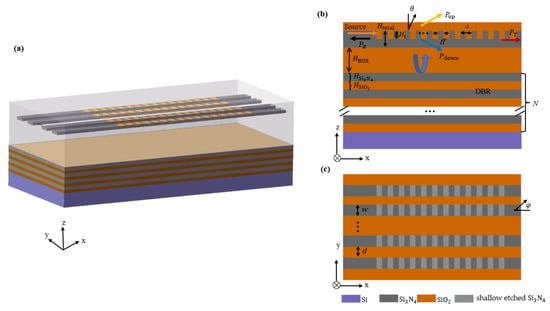
Figure 1.
(a) Three-dimensional schematic of the Si3N4 antenna with a multiple-layer DBR; (b) cross-sectional view of 400 nm thick Si3N4 antenna with a DBR and the distribution of power when light is coupled to the grating; (c) xy-view schematic of the Si3N4 antenna.
Beam steering on the -axis can be achieved by changing the wavelength of the input light, and the corresponding relationship can be expressed by the first-order Bragg condition [20]:
where nc is the refractive index of the cladding layer, is the wavelength of the input light, is the period of grating, neff = ff∙neff1 + (1−ff)∙neff2 is the effective index of the waveguide grating, ff is the filling factor, which is defined as the ratio of grating teeth to the period, neff1 is the refractive index of the grating teeth (Si3N4), and neff2 is the refractive index of the etched region.
Beam steering on the -axis can be achieved by changing the phase difference () of the adjacent waveguides. If the phase difference between the adjacent waveguides is equal, the beam steering at -axis can be calculated as [21]:
where is the uniform phase difference between adjacent channels, and d is the spacing width between the waveguides.
The beam width of a 2D array can be estimated by [21,22]:
where and are the full widths at half-maximum (FWHM) of the main lobes along the -axis and -axis, respectively, N is the number of the antennas, and L is the length of the antenna. Equation (3) shows that the beam width is determined by the aperture (Nd) of the optical antenna array. A narrow beam can be realized by increasing the number of optical antennas and the spacing width; however, the beam steering range is inversely proportional with the spacing width. Therefore, a trade-off is needed.
Figure 1b illustrates the various power distribution channels that occur when light is coupled to a silicon nitride antenna. Pup and Pdown represent the upward and downward power, respectively, while PT and PR denote the transmitted and reflected power. In order to reduce Pdown, a bottom reflector incorporating a multilayer DBR is employed.
3. Simulation and Optimizing
3.1. High Directionality Design
The three-dimensional (3D) finite-difference time-domain (FDTD) method is used to optimize antenna structures to achieve a high level of directionality. In a simulation, the fundamental transverse electric (TE) mode was used. Monitors were added in various directions to express the upward, downward, transmitted, and reflected power radiating from the grating antenna.
In order to obtain an optimal etching depth, the transmission power was calculated by varying Ht from 0 nm to 400 nm, as shown in Figure 2a, and Ht = 280 nm was chosen within the sweep range. Figure 2b illustrates the power distribution across various transmission directions as a function of filling factor variations. The filling factor affects the performance of the grating antenna by altering its effective index. The results indicate that an optimal filling factor is ff = 0.45.
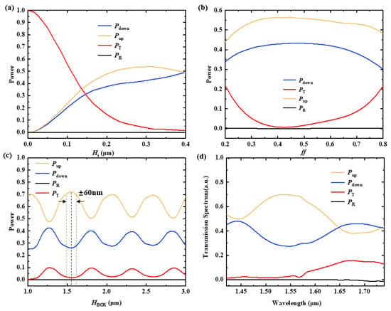
Figure 2.
(a) The power with variations in the etch depth (Ht) at a wavelength of 1550 nm; (b) the power with variations in the filling factor at a wavelength of 1550 nm; (c) after normalization, the power with variations in the HBOX at a wavelength of 1550 nm; (d) the optimized power distribution of various transmission spectrum directions with an etch depth of 0.28μm and a fill factor of 0.45.
A BOX layer between the grating antenna and the reflector was employed to prevent power leakage. The constructive interference between the reflected light and the upward radiated light can be achieved by changing the BOX thickness and therefore further reducing the loss. As shown in Figure 2c, the transmission power is highly dependent on the BOX thickness (Hbox). According to the simulation, the most optimal BOX thickness is 1.53m. However, Pup varies slightly in the range of 1.53 m ± 60 nm. As shown in Figure 2d, although parameters such as the filling factor and etch depth were optimized, the downward radiation (Pdown) still occupied quite a large portion of the total scattered power loss without a DBR. Then, a DBR consisting of a high-index material, Si3N4, and a low-index material, SiO2, was added to further reduce the downward radiation. The maximum reflectivity can be achieved when the constructive interference occurs, and the thicknesses of the Si3N4 and SiO2 layers are determined based on λ/4n [22], where λ represents the center wavelength of the source and n denotes the refractive index of materials. The thicknesses for Si3N4 and SiO2 were calculated to be 194 nm and 268 nm at λ = 1550 nm, respectively.
As Figure 3a shows, the center wavelength was fixed at 1550 nm, the reflectivity increased proportionally with the number of layers N, and the curve tended to be smooth when N ≥ 6, which attained 98% at N = 8. In order to avoid the of vertically incident effect of light on the grating antenna, an angle = 9° was chosen, and the corresponding period was 1.2 according to Equation (1). The transmission spectrum is depicted in Figure 3b as wavelength sweeps, and the DBR structure exhibits a strong reflection effect in a quite large bandwidth.
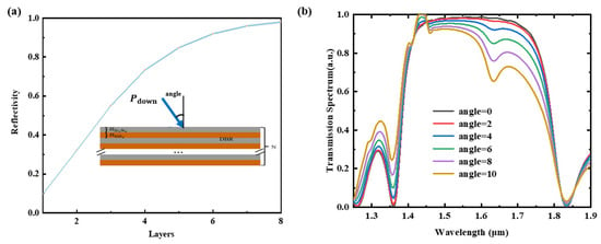
Figure 3.
(a) Reflectivity as a function of the layers when the wavelength is 1550 nm; (b) transmission spectrum depicted as a wavelength sweep by changing the angle from 0 to 10.
The variations in the reflectivity and the thicknesses of the Si3N4 film and the SiO2 film were calculated and are shown in Figure 4a,b. It can be seen that our proposed structure has quite a large fabrication tolerance.
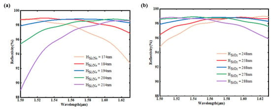
Figure 4.
(a) Shows the relationship between the reflectivity spectra and the Si3N4 film thickness variation when the SiO2 film is 268 nm; (b) shows the relationship between the reflectivity spectra and the SiO2 film thickness variation when the Si3N4 film is 194 nm while the thickness variation scanning step is 10 nm.
Figure 5 illustrates the upward directionality of the antenna corresponding to the different wavelengths. It shows that the antenna exhibits an upward directionality exceeding 71.6% within the wavelength range of 1420–1740 nm. Moreover, the upward directionality value is 97.6% at a wavelength of 1550 nm. Compared to the grating antenna without a DBR, the directionality is improved by 1.52 dB. From the comparison, Table 1, our proposed high-directionality silicon nitride grating antenna with a DBR demonstrates quite great performance.
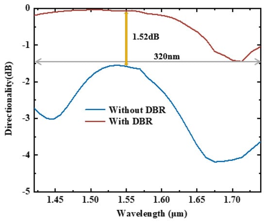
Figure 5.
Upward directionality of the antenna.

Table 1.
Comparison of the performances of the different antennas.
3.2. Array Sweep Characteristics
The characteristics of the antenna array were simulated and demonstrated. Due to a server performance limitation, a four-channel OPA antenna with a spacing width (d) of 1 μm between the waveguides was adopted. Consequently, the FWHM of the main lobe along the -axis () of antenna appeared to be large. But by increasing the antenna aperture, the could be significantly reduced, as indicated by Equation (3).
The far field of the antenna at a wavelength of 1550 nm is simulated in Figure 6a, and a narrower beam in the = -axis can be achieved by enlarging the spacing width. Figure 6b demonstrates that the proposed integrated Si3N4 grating antenna with a DBR can effectively control the emission angle along the -axis by adjusting the wavelength from 1500 nm to 1600 nm. Figure 6c shows that beam steering on -axis can be achieved by changing the phase difference of the adjacent waveguides.
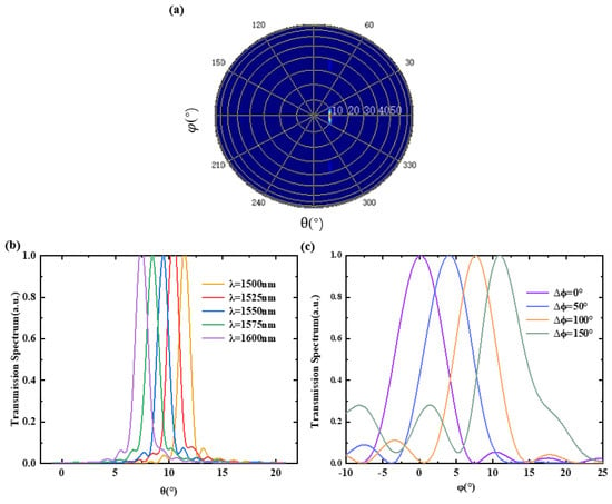
Figure 6.
(a) Far-field spot; (b) beam profiles depicted as wavelength sweeps in the -axis by changing the wavelength from 1500 nm to 1600 nm; (c) beam profiles as phase difference changes in the -axis by changing the phase difference from 0° to 150°.
4. Conclusions
In conclusion, a high-directivity Si3N4 grating antenna with a DBR is demonstrated. The directionality of the antenna is optimized by employing a DBR composed of a stack of silicon nitride and silicon dioxide as the bottom reflector. The results indicate that the directionality reaches 97.6% at a wavelength of 1550 nm and exceeds 71.6% within the wavelength range of 1420–1740 nm. The two-dimensional beam steering of our proposed antenna array is 4.09° × 6.4° (θ × φ) and can be further enlarged by utilizing a larger wavelength range and phase difference. Moreover, the optical antenna array with both a narrow beam and large steering range can be realized by using a nonuniform spacing width of the antenna array. This work provides a promising candidate for realizing high-directionality grating antennas in the integrated OPA.
Author Contributions
Conceptualization, J.W. and Y.L.; methodology, Y.Z.; software, T.D.; formal analysis, X.Z.; investigation, X.L.; writing—original draft preparation, J.W.; writing—review and editing, Y.L.; visualization, T.D.; supervision, Y.Z.; project administration, X.L.; Resources, Y.W.; funding acquisition, X.Z. All authors have read and agreed to the published version of the manuscript.
Funding
This research was funded by the National Natural Science Foundation of China (62205164, 62005242, 62134002, 61974078), Natural Science Foundation of Zhejiang (LQ20F050001), National Key Research and Development Program of China (2021YFB2800201), Natural Science Foundation of Ningbo (2021S066), the Graduate Education Practice Project of Ningbo University, No. YJD202305, and the Science and Technology Innovation 2025 Major Project of Ningbo City (2022Z203).
Data Availability Statement
Not applicable.
Conflicts of Interest
The authors declare no conflict of interest.
References
- Miller, S.A.; Chang, Y.C.; Phare, C.T.; Shin, M.C.; Zadka, M.; Roberts, S.P.; Stern, B.; Ji, X.; Mohanty, A.; Gordillo, O.A.J.; et al. Large-scale optical phased array using a low-power multi-pass silicon photonic platform. Optica 2020, 7, 3–6. [Google Scholar] [CrossRef]
- Chung, S.W.; Abediasl, H.; Hashemi, H. Monolithically integrated large-scale optical phased array in silicon-on-insulator CMOS. IEEE J. Solid-State Circuits 2018, 53, 275–296. [Google Scholar] [CrossRef]
- Hulme, J.C.; Doylend, J.K.; Heck, M.J.R.; Peters, J.D.; Davenport, M.L.; Bovington, J.T.; Coldren, L.A.; Bowers, J.E. Fully integrated hybrid silicon two dimensional beam scanner. Opt. Express 2015, 23, 5861–5874. [Google Scholar] [CrossRef]
- Xie, W.; Komljenovic, T.; Huang, J.; Tran, M.; Davenport, M.; Torres, A.; Pintus, P.; Bowers, J. Heterogeneous silicon photonics sensing for autonomous cars. Opt. Express 2019, 27, 3642–3663. [Google Scholar] [CrossRef] [PubMed]
- Hsu, C.P.; Li, B.; Solano Rivas, B.; Gohil, A.R.; Chan, P.H.; Moore, A.D.; Donzella, V. A review and perspective on optical phased array for automotive LiDAR. IEEE J. Sel. Top. Quantum Electron. 2021, 27, 8300416. [Google Scholar] [CrossRef]
- Poulton, C.V.; Byrd, M.J.; Russo, P.; Timurdogan, E.; Khandaker, M.; Vermeulen, D.; Watts, M.R. Long-range LiDAR and free-space data communication with high-performance optical phased arrays. IEEE J. Sel. Top. Quantum Electron. 2019, 25, 7700108. [Google Scholar] [CrossRef]
- Kohno, Y.; Komatsu, K.; Tang, R.; Ozeki, Y.; Nakano, Y.; Tanemura, T. Ghost imaging using a large-scale silicon photonic phased array chip. Opt. Express 2019, 27, 3817–3823. [Google Scholar] [CrossRef]
- Clevenson, H.A.; Spector, S.J.; Benney, L.; Moebius, M.G.; Brown, J.; Hare, A.; Huang, A.; Mlynarczyk, J.; Poulton, C.V.; Hosseini, E.; et al. Incoherent light imaging using an optical phased array. Appl. Phys. Lett. 2020, 116, 031105. [Google Scholar] [CrossRef]
- Sacher, W.D.; Chen, F.D.; Moradi-Chameh, H.; Liu, X.; Almog, I.F.; Lordello, T.; Chang, M.; Naderian, A.; Fowler, T.M.; Segev, E.; et al. Optical phased array neural probes for beam-steering in brain tissue. Opt. Lett. 2022, 47, 1073–1076. [Google Scholar] [CrossRef]
- Bharadwaj, P.; Deutsch, B.; Novotny, L. Optical antennas. Adv. Opt. Photonics 2009, 1, 438–483. [Google Scholar] [CrossRef]
- Guo, Y.; Guo, Y.; Li, C.; Zhang, H.; Zhou, X.; Zhang, L. Integrated optical phased arrays for beam forming and steering. Appl. Sci. 2021, 11, 4017–4058. [Google Scholar] [CrossRef]
- Kutila, M.; Pyykönen, P.; Holzhüter, H.; Colomb, M.; Duthon, P. Automotive LiDAR performance verification in fog and rain. In Proceedings of the 2018 IEEE International Conference on Intelligent Transportation Systems (ITSC), Maui, HI, USA, 4–7 November 2018; pp. 1695–1701. [Google Scholar]
- Marchetti, R.; Lacava, C.; Carroll, L.; Gradkowski, K.; Minzioni, P. Coupling strategies for silicon photonics integrated chips. Photonics Res. 2019, 7, 201–239. [Google Scholar] [CrossRef]
- Zhang, L.; Li, Y.; Hou, Y.; Wang, Y.; Tao, M.; Chen, B.; Na, Q.; Li, Y.; Zhi, Z.; Liu, X.; et al. Investigation and demonstration of a high-power handling and large-range steering optical phased array chip. Opt. Express. 2021, 29, 29755–29765. [Google Scholar] [CrossRef] [PubMed]
- Poulton, C.V.; Byrd, M.J.; Raval, M.; Su, Z.; Li, N.; Timurdogan, E.; Coolbaugh, D.; Vermeulen, D.; Watts, M.R. Large-scale silicon nitride nanophotonic phased arrays at infrared and visible wavelengths. Opt. Lett. 2017, 42, 21–24. [Google Scholar] [CrossRef] [PubMed]
- Im, C.S.; Bhandari, B.; Lee, K.P.; Kim, S.M.; Oh, M.C.; Lee, S.S. Silicon nitride optical phased array based on a grating antenna enabling wavelength-tuned beam steering. Opt. Express 2020, 28, 3270–3279. [Google Scholar] [CrossRef]
- Yu, L.; Liao, W.; Wang, P.; Ma, P.; Luo, G.; Cui, L.; Lv, C.; Zhang, Y.; Pan, J. Highly directional Si antenna based on dual-layer gratings for optical phased array. In Nanophotonics, Micro/Nano Optics, and Plasmonics VIII.; SPIE: Washington, DC, USA, 2023; pp. 1–6. [Google Scholar]
- Zaoui, W.S.; Rosa, M.F.; Vogel, W.; Berroth, M.; Butschke, J.; Letzkus, F. Cost-effective CMOS-compatible grating couplers with backside metal mirror and 69% coupling efficiency. Opt. Express 2012, 20, B238–B243. [Google Scholar] [CrossRef] [PubMed]
- Zou, J.; Yu, Y.; Ye, M.; Liu, L.; Deng, S.; Zhang, X. Ultra efficient silicon nitride grating coupler with bottom grating reflector. Opt. Express 2015, 23, 26305–26312. [Google Scholar] [CrossRef]
- Zhu, L.; Yang, W.; Chang-Hasnain, C. Very high efficiency optical coupler for silicon nanophotonic waveguide and single mode optical fiber. Opt. Express 2017, 25, 18462–18473. [Google Scholar] [CrossRef]
- Acoleyen, K.V.; Bogaerts, W.; Jana, J.; Thomas, N.L.; Romuald, H.; Baets, R. Off-chip beam steering with a one-dimensional optical phased array on silicon-on-insulator. Opt. Lett. 2009, 34, 1477–1479. [Google Scholar] [CrossRef]
- Hong, J.; Spring, A.M.; Qiu, F.; Yokoyama, S. A high efficiency silicon nitride waveguide grating coupler with a multilayer bottom reflector. Sci. Rep. 2019, 9, 12988. [Google Scholar] [CrossRef]
- Ma, P.; Luo, G.; Wang, P.; Ma, J.; Wang, R.; Yang, Z.; Zhou, X.; Zhang, Y.; Pan, J. Unidirectional SiN antenna based on dual-layer gratings for LiDAR with optical phased array. Opt. Commun. 2021, 501, 127361. [Google Scholar] [CrossRef]
- Wang, Q.; Wang, S.; Zeng, Y.; Wang, W.; Gai, Y.; Tu, Z.; Yue, W.; Wang, X.; Fang, Q.; Yu, M. Dual-layer waveguide grating antenna with high directionality for optical phased arrays. Appl. Opt. 2019, 58, 5807–5811. [Google Scholar] [CrossRef] [PubMed]
- Manan, R.; Poulton, C.V.; Watts, M.R. Unidirectional waveguide grating antennas with uniform emission for optical phased arrays. Opt. Lett. 2017, 42, 2563–2567. [Google Scholar]
Disclaimer/Publisher’s Note: The statements, opinions and data contained in all publications are solely those of the individual author(s) and contributor(s) and not of MDPI and/or the editor(s). MDPI and/or the editor(s) disclaim responsibility for any injury to people or property resulting from any ideas, methods, instructions or products referred to in the content. |
© 2023 by the authors. Licensee MDPI, Basel, Switzerland. This article is an open access article distributed under the terms and conditions of the Creative Commons Attribution (CC BY) license (https://creativecommons.org/licenses/by/4.0/).