Article

Long-Cavity M-Plane GaN-Based Vertical-Cavity Surface-Emitting Lasers with a Topside Monolithic Curved Mirror †

1
Materials Department, University of California, Santa Barbara, CA 93106, USA
2
Electrical and Computer Engineering Department, University of California, Santa Barbara, CA 93106, USA
*
Author to whom correspondence should be addressed.
This paper is an extended version of our paper published in Proceedings of the Gallium Nitride Materials and Devices XVIII; SPIE, 15 March 2023; Volume 12421, p. 127–135.
Photonics 2023, 10(6), 646; https://doi.org/10.3390/photonics10060646
Submission received: 10 May 2023 / Revised: 1 June 2023 / Accepted: 1 June 2023 / Published: 3 June 2023

Abstract

:
We report long-cavity (60.5 λ) GaN-based vertical-cavity surface-emitting lasers with a topside monolithic GaN concave mirror, a buried tunnel junction current aperture, and a bottomside nanoporous GaN distributed Bragg reflector. Under pulsed operation, a VCSEL with a 9 µm aperture had a threshold current density of 6.6 kA/cm2, a differential efficiency of 0.7%, and a maximum output power of 290 µW for a lasing mode at 411 nm and a divergence angle of 8.4°. Under CW operation, the threshold current density increased to 7.3 kA/cm2, the differential efficiency decreased to 0.4%, and a peak output power of 130 µW was reached at a current density of 23 kA/cm2.

1. Introduction

GaN-based vertical-cavity surface-emitting lasers (GaN-VCSELs) are attracting broad interest due to their low threshold currents, circular beam profiles, 2D arraying capabilities, and capability for high-frequency operation, thus promoting their applications in lighting and displays, communications, and sensing, among others [1]. While a majority of prior GaN-VCSEL demonstrations have utilized short to medium cavities (effective cavity length Leff < 3 µm) [2,3,4,5,6,7,8,9], recent long-cavity demonstrations (Leff > 10 µm) from Sony have been shown to provide high thermal stability, low threshold currents, and high output powers [10]. Until recently, this design held performance records for output power (15.4 mW) [11], threshold current (0.25 mA) [12], and wall-plug efficiency (WPE, 13.4%) [13], while reporting device yields above 90%. This design accomplishes this impressive performance by extending the cavity length and decreasing the longitudinal mode spacing such that there is always a resonant mode near the center of the gain peak, even as the gain peak has shifted due to self-heating. Lasers based on this design achieve lateral mode confinement within the long cavity by incorporating a curved III-nitride lens that is etched onto the bottom side of a polished substrate [14]. The curved lens minimizes the diffraction loss that would otherwise occur in long cavities [15]. As the cavity length increases for planar cavities with fixed mirror diameters, so does the diffraction loss; the typical gain of GaN QWs is approximately 1% per pass, so diffraction loss can quickly deteriorate device performance for cavities larger than 10 µm. However, converting one of the planar distributed Bragg reflectors (DBRs) into a curved DBR mirror is known to provide a stable resonator that forms a beam waist on the planar side, thereby minimizing diffraction loss. By confining the lateral mode in this way, the beam waist and propagation throughout the cavity are primarily determined by the cavity length (L) and the radius of curvature (ROC) of the mirror.
The design demonstrated by Hamaguchi et al. prioritized low-threshold conditions by placing the active region at the beam waist (100 nm from the planar mirror) and minimizing the aperture size. However, to form their lens, they had to polish the substrate down to a thickness of approximately 20 µm, thus increasing processing complexity. Additionally, placing the mirror on the bottom of the substrate requires backside alignment. It is beneficial to place the lens on top of the VCSEL cavity without needing to lap or polish the substrate down to the desired cavity thickness. For the bottomside mirror, an epitaxial option would remove the necessity for substrate thinning or flip-chip bonding.
Here, we present a long-cavity (Leff~60.5λ) m-plane GaN-VCSEL with a topside monolithic GaN concave mirror, a buried tunnel junction (BTJ), and a buried planar nanoporous GaN distributed Bragg reflector (NP DBR) that lases under CW operation. The GaN mirror has a diameter of 26 µm and an ROC of 31 µm. The active region is placed approximately 6.5 µm from the planar mirror.

2. Materials and Methods

The epitaxial device structure, shown in Figure 1 and summarized in Table 1, was grown using atmospheric metalorganic chemical vapor deposition (MOCVD) on free-standing single-side polished (SSP) m-plane (10 1 ¯ 0) substrates with an intentional 1° miscut in the [000 1 ¯ ] direction. The epitaxial structure consisted of a 1 µm n-GaN ([Si]~2 × 1018 cm−3) buffer layer grown at 1000 °C (18 nm/min); 24 pairs of alternating unintentionally doped (UID) GaN ([Si]~1 × 1016 cm−3) and n+–GaN ([Si]~4 × 1019 cm−3) grown at 1180 °C (50 nm/min) to form the bottomside DBR; 3860 nm of UID GaN grown at 1000 °C (45 nm/min); 2500 nm of n-GaN ([Si]~8 × 1018 cm−3 grown at 1000 °C (43 nm/min); 2 × 8 nm InGaN quantum wells (MQWs) designed to emit at 410 nm with 3 nm GaN barriers grown at 857 °C (6 nm/min); 5 nm UID GaN grown at 857 °C (6 nm/min); 10 nm graded p-AlGaN ([Mg] ~1 × 1019 cm−3) electron blocking layer (EBL) graded along the growth direction from 30% to 0% and grown at 1000 °C (6 nm/min); 80 nm p-GaN ([Mg]~1 × 1019 cm−3) grown at 1000 °C (8 nm/min); and 10.5nm p++–GaN ([Mg]~3 × 1020 cm−3) grown at 1000 °C (8 nm/min). After the first growth, the samples were treated with concentrated HF and ozone before regrowing the 8 nm n++–GaN ([Si]~1.5 × 1020 cm−3) TJ layer at 825 °C (2 nm/min) via MOCVD [16]. The buried tunnel junction (BTJ) current apertures were defined by etching 30 nm through the n++/p++–GaN layers using reactive-ion etching (RIE). Then, all samples were annealed at 730 °C in a 4:1 N2/O2 environment for 30 min to activate the p/p++–GaN [17]. Finally, 1810 nm n-GaN ([Si]~4 × 1018 cm−3) and 1700 nm UID GaN were grown at 900 °C (45 nm/min) via MOCVD.
The photoresist lenses were formed via photoresist reflow and then transferred into the upper UID/n-GaN layers using RIE [19]. Next, SiO2 was deposited on the curved GaN lenses using plasma-enhanced chemical vapor deposition (PECVD) to act as a hard mask for subsequent processing steps. Following this, mesas were defined using RIE to allow for the p-GaN to be activated through the mesa sidewalls [20]. Next, 7 µm deep and 15 µm wide trenches were defined using RIE to etch the NP DBR. Then, all samples were annealed again at 730 C in a N2/O2 environment for 30 min to re-activate the BTJ through the mesa sidewalls. Next, 25 nm SiO2 was deposited on both the top and sidewall surfaces of the mesa using atomic layer deposition (ALD) to protect the devices from the NP DBR acid etch and to provide electrical isolation [21] and sidewall passivation [22]. Next, the backside of the substrate was coated with 40 nm/450 nm Ti/Au using electron-beam evaporation, and then the samples were taped to a conductive steel holder and submerged in 0.3 M oxalic acid. A Pt wire was submerged alongside the substrate, and a bias of 2.4 V was applied for 30 h to etch the NP DBRs. Under these conditions, the n+–GaN layers of the DBR chemically reacted with the oxalic acid and formed a porous structure with pores ranging from 20 to 40 nm in diameter [23]. After the etch was completed, the bottom metal was removed with adhesive tape, and metal contacts comprised of Ti/Au (40 nm/450 nm) were deposited using electron-beam evaporation on top of the n-type GaN on the topside of the mesa and slightly overlapping the edge of the lens. Finally, a 16-period SiO2/Ta2O5 dielectric DBR was deposited on the topside of the lenses using ion beam deposition (IBD).
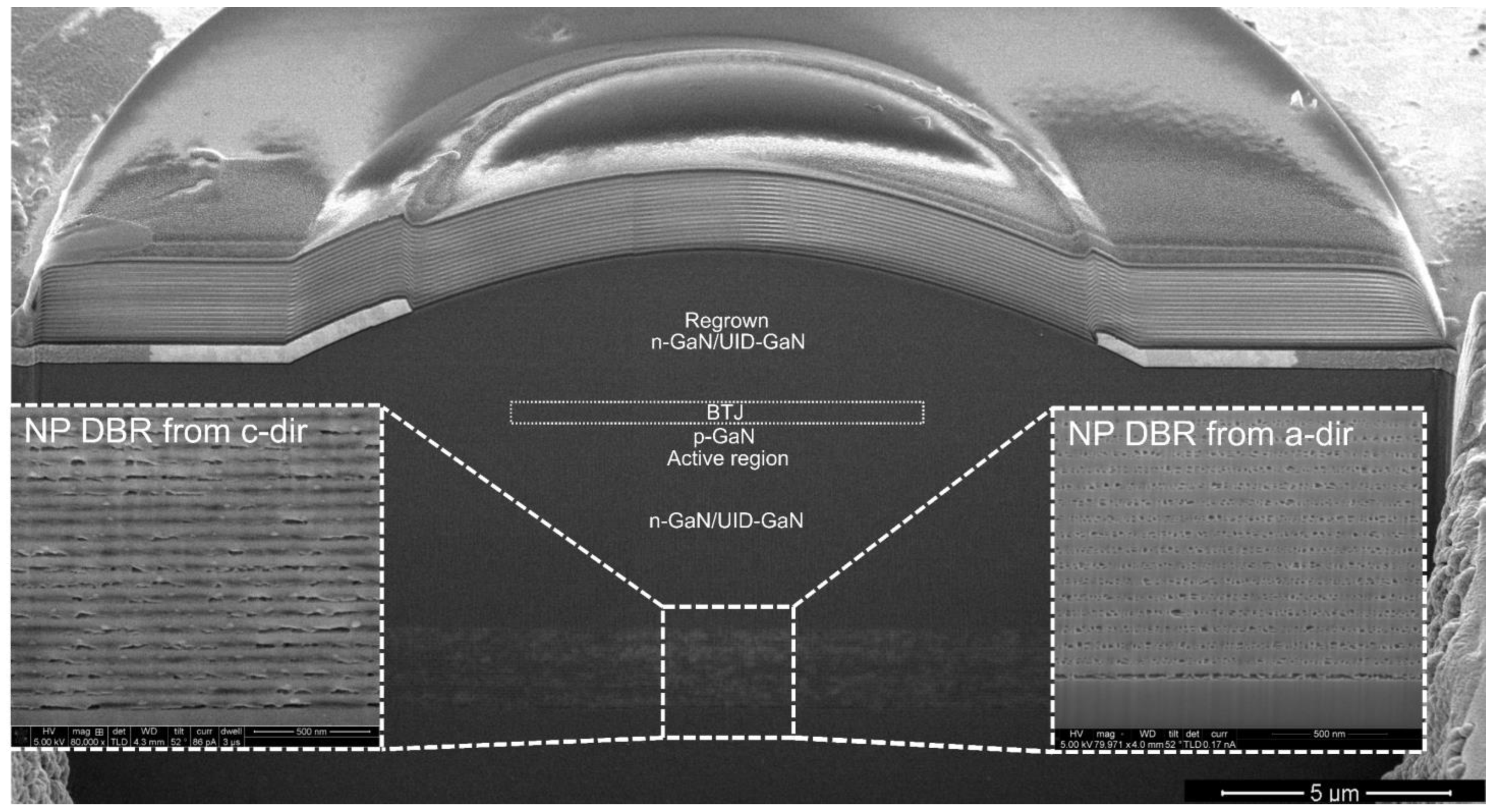
A cross section of a completed device, taken using a focused ion beam (FIB) and imaged using scanning electron microscopy (SEM), is shown in Figure 2. Electrical characteristics were analyzed under pulsed operation with a 1000 ns pulse width and a 1% duty cycle, and under continuous-wave (CW) operation, both at room temperature (20 °C). Optical power measurements were taken by placing the sample directly on top of a Thorlabs bandpass filter centered at 410 nm with a peak transmittance of 91%; the sample and filter were placed onto a 3 mm diameter silicon photodetector (model DET36A) reverse-biased at 10 V for pulsed measurements, and placed onto a wide-area 12 mm diameter unbiased silicon photodetector (PD) for CW measurements. The bandpass filter was employed because of excess spontaneous emission present in the unfiltered LIV measurement due to the close proximity of the device to the PD, which washed out the expected LI kink. The spectrum data were acquired using an Ocean Insight spectrometer with a spectral resolution of 2 nm. The topside nearfield patterns (NFP) were taken using an optical microscope with a 20x objective lens, and the bottomside farfield patterns (FFP) were taken by placing a piece of fluorescent paper 16.5 mm below the device, which was mounted to a double-side polished (DSP) sapphire substrate. The 16.5 mm thickness included the thickness of the DSP sapphire. The resulting mode was imaged with a camera mounted at 35°.

3. Results and Discussion

The root-mean-square (RMS) roughness for the final regrowth surface was approximately 0.7 nm, as measured using atomic force microscopy (AFM). The fabricated devices had an effective cavity length of approximately 60.5 λ (10.7 μm) for a target emission wavelength of 410 nm. The cross-sectional SEM images of the NP DBR are shown in the insets of Figure 2, with pictures taken of the pores in the c- and a-directions. The porosity of the NP DBR was extracted by binarizing the SEM image in the a-direction and calculating the porous fraction from the known thicknesses of the individual layers. Using this method, a porosity of 29% was calculated. From there, the index of refraction of the porous layer, npor, can be determined based on the volume average theory (VAT) as follows:
n p o r = [ ( 1 φ ) n G a N 2 + φ n a i r 2 ] 1 / 2
where φ describes the porosity fraction [24]. At 410 nm, the nGaN was ~2.5, leading to a calculated npor of ~2.18 and creating an index contrast of 0.32. Using 1D transmission matrix method (1D TMM) simulations, the peak reflectivity of the 24-period NP DBR was 99.617%. There is inhomogeneity of the pore size observed throughout the NP DBR layers, which may lead to scattering [25]. Future studies will be conducted to further characterize the magnitude of this effect within NP DBRs for III-nitride VCSELs. Additional 1D TMM simulations were carried out to calculate the internal loss <αi>, mirror loss αm, confinement factor ΓxyΓzΓenh, and dielectric DBR reflectivity, which were determined to be 2.52 cm−1, 1.8 cm−1, 0.00117, and 99.995%, respectively [26]. The absorption coefficients listed in Table 1 are rough estimates used to guide insights into the internal loss of the structure [18].
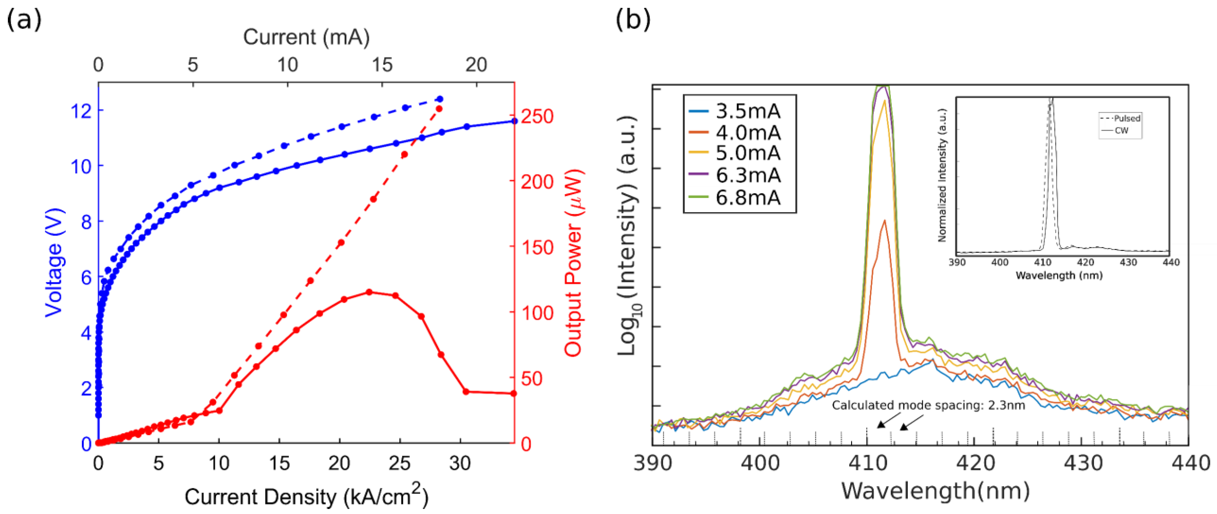
Figure 3a shows the light-current-voltage (LIV) characteristics of a VCSEL with a 9 µm current aperture analyzed under pulsed and CW operations. Under pulsed operation, the peak total output power was 260 μW and the threshold current (Jth) and voltage (Vth) were 6.6 kA/cm2 and 8.9 V, respectively, as determined using the linear line fitting method. Correcting for the filter transmittance gave a peak output power of 290 µW. The slope efficiency (SE) was 0.02 W/A, leading to a differential efficiency (ηd) of 0.7%. Under CW operation, Jth and Vth were 7.3 kA/cm2 and 8.8 V, respectively, with rollover occurring at approximately 23 kA/cm2 at a peak total power of 120 μW, or 130 µW with filter correction. The SE reduced to 0.013 W/A, resulting in a reduced ηd of 0.4%.
The diameter of a Gaussian beam, 2ω(z), at the location of the active region can be expressed using the following equation [27]:
2 ω ( z ) = 2 ω 0 1 + ( λ z n π ω 0 2 ) 2
where λ is the lasing wavelength and n is the index refraction. ω0 is the beam waist radius formed at the planar mirror and can be calculated as follows:
ω 0 = λ n π L e f f R L e f f 2
where Leff is the effective cavity length and R is the ROC of the concave lens. At the active region, which is placed approximately 6.5 µm from the planar mirror, 99.7% of the Gaussian profile is contained in a 5.8 µm diameter. This was calculated by calculating the beam diameter using Equations (2) and (3), and then multiplying the result by three to account for 99.7% of the light. The result suggests that only 41% of the 9 µm current aperture is coupled to the resonant mode, and the remaining light becomes excess spontaneous emission. Additionally, there is current crowding observed around the edge of the 9 μm aperture. This non-uniformity in current distribution could lead to increased recombination at the edge of the aperture and outside of the mode, which is approximately centered over the aperture. Figure 3b shows the unfiltered spectra as a function of the injected current under pulsed operation, showing the selection of a mode centered at 411 nm that grows with the injected current. The inset of Figure 3b shows the lasing behavior at a bias of 8 mA under pulsed and CW operations, showing a minimal shift of the mode at the injected current. It should be noted that the resolution of the spectrometer (2 nm) is similar to the longitudinal-mode spacing calculated using 1D TMM modeling (2.3 nm). The arrows designate adjacent longitudinal peak positions, which are almost at the same position of the observed peak emission wavelength. Additional equipment is needed to accurately resolve the longitudinal-mode behavior.
Prior NP-DBR VCSEL demonstrations with cavity lengths of 8.9λ [28], 6λ [6], 6λ [7], and 1.5λ [29] exhibited threshold currents of 20 kA/cm2 (pulsed), 42 kA/cm2 (pulsed), 59 kA/cm2 (pulsed), and 0.7 kA/cm2 (CW), respectively. Previous curved mirror VCSEL demonstrations exhibited threshold current densities that ranged from 3.5 to 141 kA/cm2 [10,11,14,30,31]. Our device performs favorably compared to prior NP-DBR VCSEL demonstrations, and the results are in line with prior curved mirror VCSEL demonstrations. However, we note that the threshold current density calculated from the threshold current divided by the current aperture area is not always an accurate metric, given that the injected current density is seldom uniform over the aperture and that the optical mode diameter is usually smaller than the current aperture diameter [9].
CW performance is limited by thermal rollover, which is caused by a higher than anticipated voltage. A high voltage is believed to be caused by incomplete activation of the TJ interface in the BTJ [5,32], which is a problem exacerbated by the thick n-GaN regrowth immediately following the BTJ etch. Additionally, the Mg doping within the p++-GaN of the BTJ is approximately [Mg] = 3 × 1020 cm−3 as measured using secondary ion mass spectrometry (SIMS), potentially leading to passivating Mg-H complexes at or near the TJ interface [33].
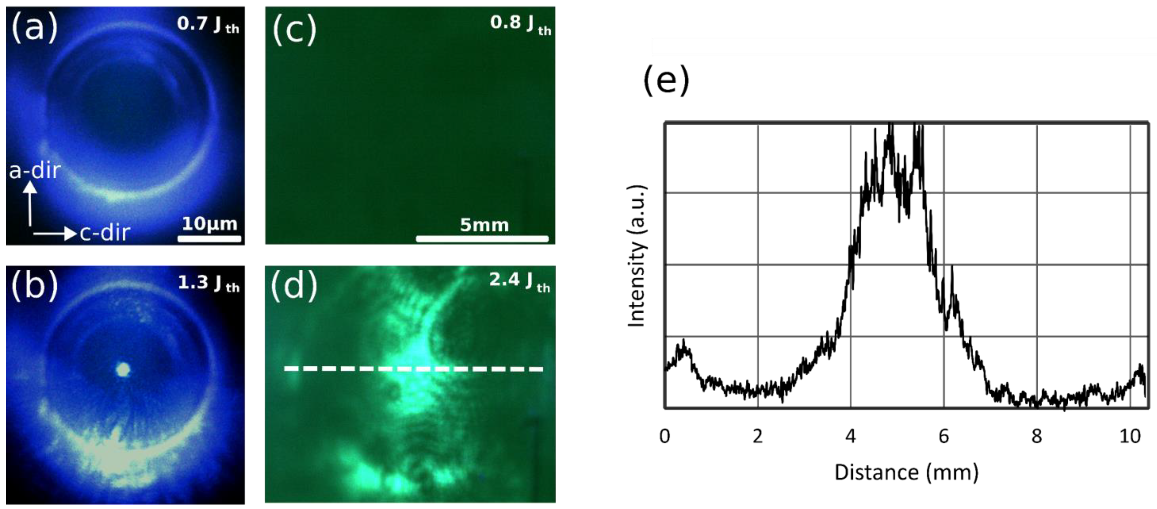
Figure 4a,b show the topside NFP images taken of the device below and above Jth. Above the threshold, a bright spot appears above the BTJ at the center of the lens that is approximately 2 µm wide. The spot diameter for a fundamental Gaussian beam at the concave mirror is calculated using the following equation [34]:
2 ω c o n c a v e = 2 λ n π L e f f 2 R 2 L e f f R L e f f 2
For this design, the beam diameter was calculated to be 2.15 µm, which is in agreement with the observed experimental value.
Figure 4c,d show the fluorescent paper when illuminated through the bottomside of the VCSEL below Jth and above Jth at a bias of 10 mA. The rough SSP GaN substrate contributes to the significant scattering of the mode. However, a rough central lateral mode shape appears above the threshold and grows with the injected current. Figure 4e shows a 2D line scan of the mode, with a full width at half maximum (FWHM) of approximately 2.9 mm. The fluorescent paper was placed 16.5 mm away from the bottom of the 250 µm thick GaN substrate, leading to an extracted divergence half-angle, θFWHM, of 8.4°. This value is comparable to the theoretical θFWHM ≈ 10° calculated using the following equation [27]:
θ F W H M = 2 l n 2 λ π ω 0
Taking the radius of the spot observed in the topside NFP in Figure 4b and applying it to Equation (5) gives an expected topside θFWHM of 8.8°, which is in reasonable agreement with the bottomside value. The experimental top and bottom θFWHM values are in line with recent curved mirror cavity demonstrations, which reported divergence half-angles of 8.5° and 3.9° [11,35], but higher than recent planar cavity demonstrations, which reported divergence half-angles of 5.1° and 2.8° [3,36].

4. Conclusions

In summary, 60.5 λ cavity GaN-VCSELs utilizing a topside curved mirror, BTJ, and NP DBR were successfully fabricated. The peak output power for a 9 µm aperture under pulsed operation was 290 µW, with a Jth of 6.6 kA/cm2 and ηd of 0.7%. Under CW operation, Jth increased to 7.3 kA/cm2, ηd decreased to 0.4%, and the peak output power at rollover was 130 µW. The bottomside FFP images show that the divergence half-angle was approximately 8.4°.

Author Contributions

Conceptualization, N.C.P., R.A. and J.A.K.; data curation, N.C.P.; formal analysis, E.T.; funding acquisition, S.P.D. and S.N.; investigation, N.C.P., J.A.K. and J.B.; software, R.A. and S.G. All authors have read and agreed to the published version of the manuscript.

Funding

This work was funded by the Solid-State Lighting and Energy Electronics Center (SSLEEC) at UCSB.

Data Availability Statement

The results presented in this paper are not available publicly at this time but may be obtained from the authors upon reasonable request.

Acknowledgments

A portion of this work was carried out at the UCSB nanofabrication facility, the UCSB Materials Research Laboratory (NSF DMR 1720256), the NRI-MCDB Microscopy Facility (NSF DBR-1625770), and the California Nano System Institute (CNSI).

Conflicts of Interest

The authors declare no conflict of interest.

References

  1. Michalzik, R. VCSELs: Fundamentals, Technology and Applications of Vertical-Cavity Surface-Emitting Lasers; Springer Series in Optical Sciences; Springer: Berlin/Heidelberg, Germany, 2013; ISBN 978-3-642-24985-3. [Google Scholar]
  2. Hayashi, N.; Ogimoto, J.; Matsui, K.; Furuta, T.; Akagi, T.; Iwayama, S.; Takeuchi, T.; Kamiyama, S.; Iwaya, M.; Akasaki, I. A GaN-Based VCSEL with a Convex Structure for Optical Guiding. Phys. Status Solidi A 2018, 215, 1700648. [Google Scholar] [CrossRef] [Green Version]
  3. Kuramoto, M.; Kobayashi, S.; Akagi, T.; Tazawa, K.; Tanaka, K.; Saito, T.; Takeuchi, T. High-Power GaN-Based Vertical-Cavity Surface-Emitting Lasers with AlInN/GaN Distributed Bragg Reflectors. Appl. Sci. 2019, 9, 416. [Google Scholar] [CrossRef] [Green Version]
  4. Leonard, J.T.; Cohen, D.A.; Yonkee, B.P.; Farrell, R.M.; Margalith, T.; Lee, S.; DenBaars, S.P.; Speck, J.S.; Nakamura, S. Nonpolar III-Nitride Vertical-Cavity Surface-Emitting Lasers Incorporating an Ion Implanted Aperture. Appl. Phys. Lett. 2015, 107, 011102. [Google Scholar] [CrossRef]
  5. Kearns, J.A.; Back, J.; Cohen, D.A.; DenBaars, S.P.; Nakamura, S. Demonstration of Blue Semipolar (2021) GaN-Based Vertical-Cavity Surface-Emitting Lasers. Opt. Express 2019, 27, 23707. [Google Scholar] [CrossRef]
  6. ElAfandy, R.T.; Kang, J.-H.; Li, B.; Kim, T.K.; Kwak, J.S.; Han, J. Room-Temperature Operation of c-Plane GaN Vertical Cavity Surface Emitting Laser on Conductive Nanoporous Distributed Bragg Reflector. Appl. Phys. Lett. 2020, 117, 011101. [Google Scholar] [CrossRef]
  7. Elafandy, R.T.; Kang, J.-H.; Mi, C.; Kim, T.K.; Kwak, J.S.; Han, J. Study and Application of Birefringent Nanoporous GaN in the Polarization Control of Blue Vertical-Cavity Surface-Emitting Lasers. ACS Photonics 2021, 8, 1041–1047. [Google Scholar] [CrossRef]
  8. Kiyohara, K.; Odawara, M.; Takeuchi, T.; Kamiyama, S.; Iwaya, M.; Akasaki, I.; Saito, T. Room-Temperature Continuous-Wave Operations of GaN-Based Vertical-Cavity Surface-Emitting Lasers with Buried GaInN Tunnel Junctions. Appl. Phys. Express 2020, 13, 111003. [Google Scholar] [CrossRef]
  9. Kearns, J.A.; Back, J.; Palmquist, N.C.; Cohen, D.A.; DenBaars, S.P.; Nakamura, S. Inhomogeneous Current Injection and Filamentary Lasing of Semipolar (2021¯) Blue GaN-Based Vertical-Cavity Surface-Emitting Lasers with Buried Tunnel Junctions. Phys. Status Solidi (A) 2019, 217, 1900718. [Google Scholar] [CrossRef]
  10. Hamaguchi, T.; Tanaka, M.; Nakajima, H. A Review on the Latest Progress of Visible GaN-Based VCSELs with Lateral Confinement by Curved Dielectric DBR Reflector and Boron Ion Implantation. Jpn. J. Appl. Phys. 2019, 58, SC0806. [Google Scholar] [CrossRef]
  11. Nakajima, H.; Hamaguchi, T.; Tanaka, M.; Ito, M.; Jyokawa, T.; Matou, T.; Hayashi, K.; Ohara, M.; Kobayashi, N.; Watanabe, H.; et al. Single Transverse Mode Operation of GaN-Based Vertical-Cavity Surface-Emitting Laser with Monolithically Incorporated Curved Mirror. Appl. Phys. Express 2019, 12, 084003. [Google Scholar] [CrossRef] [Green Version]
  12. Hamaguchi, T.; Nakajima, H.; Tanaka, M.; Ito, M.; Ohara, M.; Jyoukawa, T.; Kobayashi, N.; Matou, T.; Hayashi, K.; Watanabe, H.; et al. Sub-Milliampere-Threshold Continuous Wave Operation of GaN-Based Vertical-Cavity Surface-Emitting Laser with Lateral Optical Confinement by Curved Mirror. Appl. Phys. Express 2019, 12, 044004. [Google Scholar] [CrossRef]
  13. Ito, M.; Hamaguchi, T.; Makino, T.; Hayashi, K.; Kearns, J.; Ohara, M.; Kobayashi, N.; Nagane, S.; Sato, K.; Nakamura, Y.; et al. Highly Efficient Operation and Uniform Characteristics of Curved Mirror Vertical-Cavity Surface-Emitting Lasers. Appl. Phys. Express 2022, 16, 012006. [Google Scholar] [CrossRef]
  14. Hamaguchi, T.; Tanaka, M.; Mitomo, J.; Nakajima, H.; Ito, M.; Ohara, M.; Kobayashi, N.; Fujii, K.; Watanabe, H.; Satou, S.; et al. Lateral Optical Confinement of GaN-Based VCSEL Using an Atomically Smooth Monolithic Curved Mirror. Sci. Rep. 2018, 8, 10350. [Google Scholar] [CrossRef] [Green Version]
  15. Kogelnik, H.; Li, T. Laser Beams and Resonators. Appl. Opt. AO 1966, 5, 1550–1567. [Google Scholar] [CrossRef]
  16. Hwang, D.; Mughal, A.; Wong, M.; Alhassan, A.; Nakamura, S.; Denbaars, S. Micro-Light-Emitting Diodes with III–Nitride Tunnel Junction Contacts Grown by Metalorganic Chemical Vapor Deposition. Appl. Phys. Express 2018, 11, 012102. [Google Scholar] [CrossRef]
  17. Wong, M.S.; Palmquist, N.C.; Jiang, J.; Chan, P.; Lee, C.; Li, P.; Kang, J.H.; Baek, Y.H.; Kim, C.H.; Cohen, D.A.; et al. Effects of Activation Method and Temperature to III-Nitride Micro-Light-Emitting Diodes with Tunnel Junction Contacts Grown by Metalorganic Chemical Vapor Deposition. Appl. Phys. Lett. 2021, 119, 202102. [Google Scholar] [CrossRef]
  18. Kioupakis, E.; Rinke, P.; Van de Walle, C.G. Determination of Internal Loss in Nitride Lasers from First Principles. Appl. Phys. Express 2010, 3, 082101. [Google Scholar] [CrossRef]
  19. Nussbaum, P.; Völkel, R.; Herzig, H.P.; Eisner, M.; Haselbeck, S. Design, Fabrication and Testing of Microlens Arrays for Sensors and Microsystems. Pure Appl. Opt. 1997, 6, 617–636. [Google Scholar] [CrossRef] [Green Version]
  20. Kuwano, Y.; Kaga, M.; Morita, T.; Yamashita, K.; Yagi, K.; Iwaya, M.; Takeuchi, T.; Kamiyama, S.; Akasaki, I. Lateral Hydrogen Diffusion at P-GaN Layers in Nitride-Based Light Emitting Diodes with Tunnel Junctions. Jpn. J. Appl. Phys. 2013, 52, 08JK12. [Google Scholar] [CrossRef]
  21. Palmquist, N.C.; Anderson, R.; Kearns, J.A.; Back, J.; Trageser, E.; Gee, S.; Denbaars, S.P.; Nakamura, S. Continuous-Wave Operation of Long-Cavity m-Plane GaN-Based Vertical-Cavity Surface-Emitting Lasers with a Topside Curved Mirror and Nanoporous GaN DBR. In Proceedings of the Gallium Nitride Materials and Devices XVIII, San Francisco, CA, USA, 15 March 2023; Volume 12421, pp. 127–135. [Google Scholar]
  22. Wong, M.S.; Hwang, D.; Alhassan, A.I.; Lee, C.; Ley, R.; Nakamura, S.; DenBaars, S.P. High Efficiency of III-Nitride Micro-Light-Emitting Diodes by Sidewall Passivation Using Atomic Layer Deposition. Opt. Express OE 2018, 26, 21324–21331. [Google Scholar] [CrossRef]
  23. Zhang, C.; Park, S.H.; Chen, D.; Lin, D.-W.; Xiong, W.; Kuo, H.-C.; Lin, C.-F.; Cao, H.; Han, J. Mesoporous GaN for Photonic Engineering—Highly Reflective GaN Mirrors as an Example. ACS Photonics 2015, 2, 980–986. [Google Scholar] [CrossRef]
  24. Braun, M.M.; Pilon, L. Effective Optical Properties of Non-Absorbing Nanoporous Thin Films. Thin Solid Films 2006, 496, 505–514. [Google Scholar] [CrossRef]
  25. Anderson, R.; Cohen, D.; Zhang, H.; Trageser, E.; Palmquist, N.; Nakamura, S.; DenBaars, S. Nano-Porous GaN Cladding and Scattering Loss in Edge Emitting Laser Diodes. Opt. Express OE 2022, 30, 2759–2767. [Google Scholar] [CrossRef]
  26. Leonard, J.T.; Young, E.C.; Yonkee, B.P.; Cohen, D.A.; Margalith, T.; DenBaars, S.P.; Speck, J.S.; Nakamura, S. Demonstration of a III-Nitride Vertical-Cavity Surface-Emitting Laser with a III-Nitride Tunnel Junction Intracavity Contact. Appl. Phys. Lett. 2015, 107, 091105. [Google Scholar] [CrossRef]
  27. Yariv, A. Optical Electronics, 3rd ed.; Saunders College Publishing: Philadelphia, PA, USA, 1991; ISBN 978-1-60049-013-2. [Google Scholar]
  28. Mishkat-Ul-Masabih, S.M.; Aragon, A.A.; Monavarian, M.; Luk, T.S.; Feezell, D.F. Electrically Injected Nonpolar GaN-Based VCSELs with Lattice-Matched Nanoporous Distributed Bragg Reflector Mirrors. Appl. Phys. Express 2019, 12, 036504. [Google Scholar] [CrossRef]
  29. Ke, Y.; Wang, C.-J.; Shiu, G.-Y.; Chen, Y.-Y.; Lin, Y.-S.; Chen, H.; Han, J.; Lin, C.-F. Polarization Properties of InGaN Vertical-Cavity Surface-Emitting Laser with Pipe Distributed Bragg Reflector. IEEE Trans. Electron. Devices 2022, 69, 201–204. [Google Scholar] [CrossRef]
  30. Hamaguchi, T.; Hoshina, Y.; Hayashi, K.; Tanaka, M.; Ito, M.; Ohara, M.; Jyoukawa, T.; Kobayashi, N.; Watanabe, H.; Yokozeki, M.; et al. Room-Temperature Continuous-Wave Operation of Green Vertical-Cavity Surface-Emitting Lasers with a Curved Mirror Fabricated on (2021) Semi-Polar GaN. Appl. Phys. Express 2020, 13, 041002. [Google Scholar] [CrossRef]
  31. Kearns, J.; Hamaguchi, T.; Hayashi, K.; Ohara, M.; Makino, T.; Ito, M.; Kobayashi, N.; Jyoukawa, T.; Nakayama, E.; Nagane, S.; et al. Longitudinal Mode Control in Long Cavity VCSELs with a Curved Mirror. Appl. Phys. Express 2022, 15, 072009. [Google Scholar] [CrossRef]
  32. Leonard, J.T.; Yonkee, B.P.; Cohen, D.A.; Megalini, L.; Lee, S.; Speck, J.S.; DenBaars, S.P.; Nakamura, S. Nonpolar III-Nitride Vertical-Cavity Surface-Emitting Laser with a Photoelectrochemically Etched Air-Gap Aperture. Appl. Phys. Lett. 2016, 108, 031111. [Google Scholar] [CrossRef]
  33. Castiglia, A.; Carlin, J.-F.; Grandjean, N. Role of Stable and Metastable Mg–H Complexes in p-Type GaN for Cw Blue Laser Diodes. Appl. Phys. Lett. 2011, 98, 213505. [Google Scholar] [CrossRef]
  34. Aldaz, R.I.; Wiemer, M.W.; Miller, D.A.B.; Harris, J.S. Monolithically-Integrated Long Vertical Cavity Surface Emitting Laser Incorporating a Concave Micromirror on a Glass Substrate. Opt. Express OE 2004, 12, 3967–3971. [Google Scholar] [CrossRef] [PubMed] [Green Version]
  35. Hayashi, K.; Hamaguchi, T.; Kearns, J.A.; Kobayashi, N.; Ohara, M.; Makino, T.; Nagane, S.; Sato, K.; Nakamura, Y.; Hoshina, Y.; et al. Narrow Emission of Blue GaN-Based Vertical-Cavity Surface-Emitting Lasers With a Curved Mirror. IEEE Photonics J. 2022, 14, 1–5. [Google Scholar] [CrossRef]
  36. Kuramoto, M.; Kobayashi, S.; Tazawa, K.; Tanaka, K.; Akagi, T.; Saito, T. In-Phase Supermode Operation in GaN-Based Vertical-Cavity Surface-Emitting Laser. Appl. Phys. Lett. 2019, 115, 041101. [Google Scholar] [CrossRef]
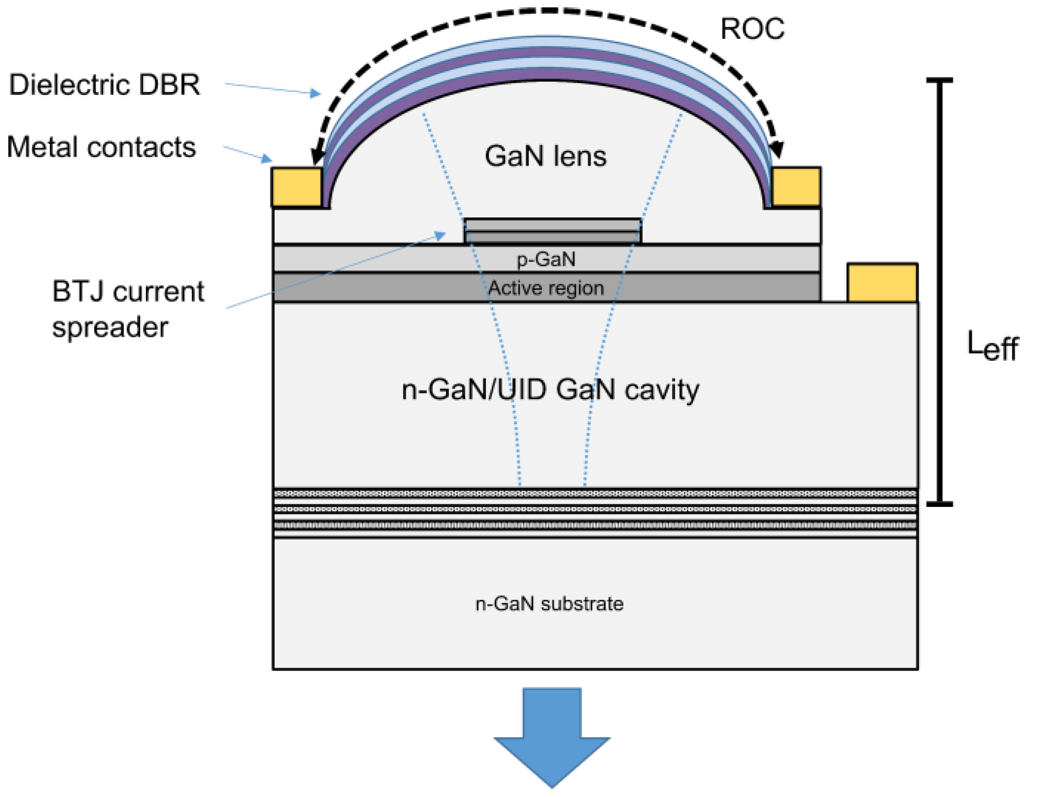
Figure 1. Schematic of the VCSEL structure with a topside curved GaN mirror.
Photonics 10 00646 g001
Figure 2. Cross-sectional scanning electron microscopic (SEM) image of the fabricated device structure, with the insets showing the cross sections of the NP DBR from the c- and a-directions.
Photonics 10 00646 g002
Figure 3. (a) LIV for pulsed (solid) and CW (dashed) operations of a VCSEL with a 9 µm current aperture. The inset features LI for pulsed (solid) and CW (dashed) operations through a Thorlabs bandpass filter. (b) Pulsed emission spectrum as a function of injected current. The inset shows the comparison between the pulsed and CW spectra taken at 8 mA (12.5 kA/cm2). The arrows designate adjacent longitudinal peak positions.
Photonics 10 00646 g003
Figure 4. (a,b) Optical microscopic images of a 9 µm diameter aperture VCSEL below and above Jth (pulsed), respectively. (c,d) Captured images of the bottomside FFP of the same VCSEL below and above Jth, respectively. (e) Cross-sectional profile of the bottomside FFP above Jth taken along the c-direction.
Photonics 10 00646 g004
Table 1. Epitaxial structure, doping concentrations, and absorption coefficients [18].
Growth StepLayerThickness (nm)Doping Conc. (cm−3)Abs. Coeff. (cm−1)
SiO2/Ta2O5 DBR
(16–periods)
67.5/45.5NA 0
GaN1700UID 2
3rd n-GaN18108 × 1018 2
2nd n++–GaN81.5 × 1020 235
1st p++–GaN10.52.5 × 1020 180
p-GaN801 × 1019 80
p-AlGaN EBL101 × 1019 27
GaN barrier5UID 2
GaN/InGaN QW (2x)3/8UID 0
n-GaN25008 × 1018 2
GaN3860UID 2
n+–GaN/GaN DBR (24–periods)48.4/40.45 × 1019/UID 0/0
Disclaimer/Publisher’s Note: The statements, opinions and data contained in all publications are solely those of the individual author(s) and contributor(s) and not of MDPI and/or the editor(s). MDPI and/or the editor(s) disclaim responsibility for any injury to people or property resulting from any ideas, methods, instructions or products referred to in the content.