Fabrication of Selective Thermal Emitter with Multilayer Films for Mid-/Low-Temperature Infrared Stealth with Radiative Cooling

 and
and 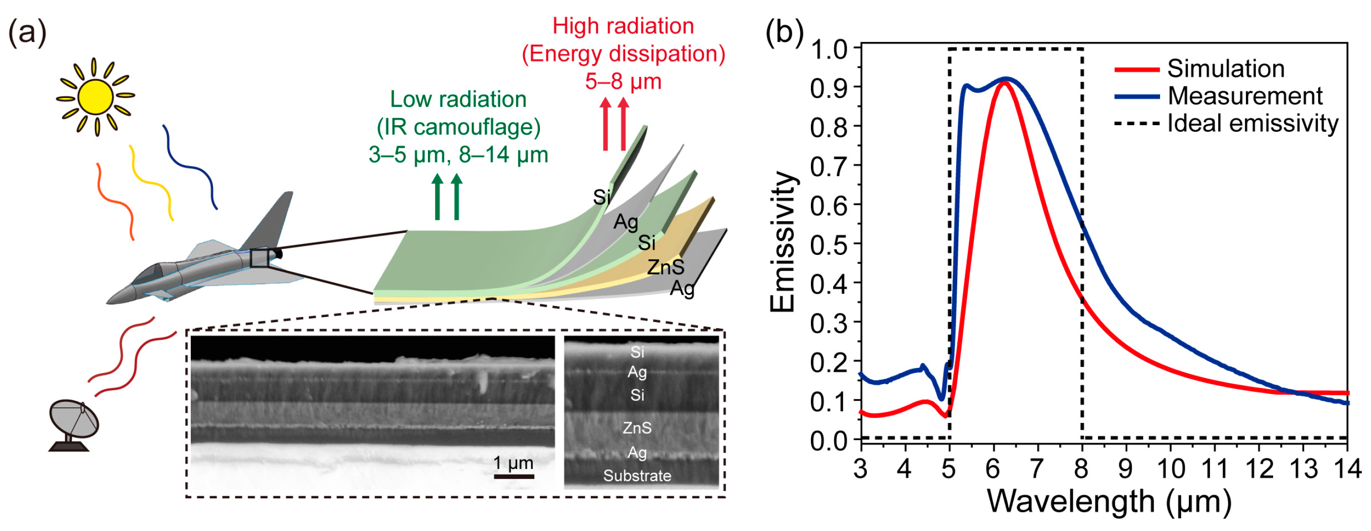
Abstract
1. Introduction
2. Materials and Methods
3. Results and Discussion
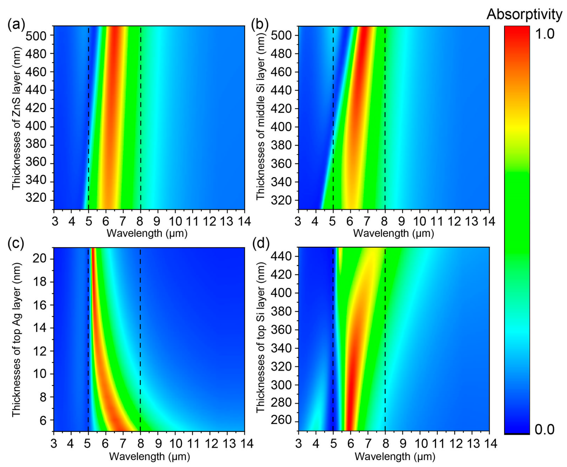
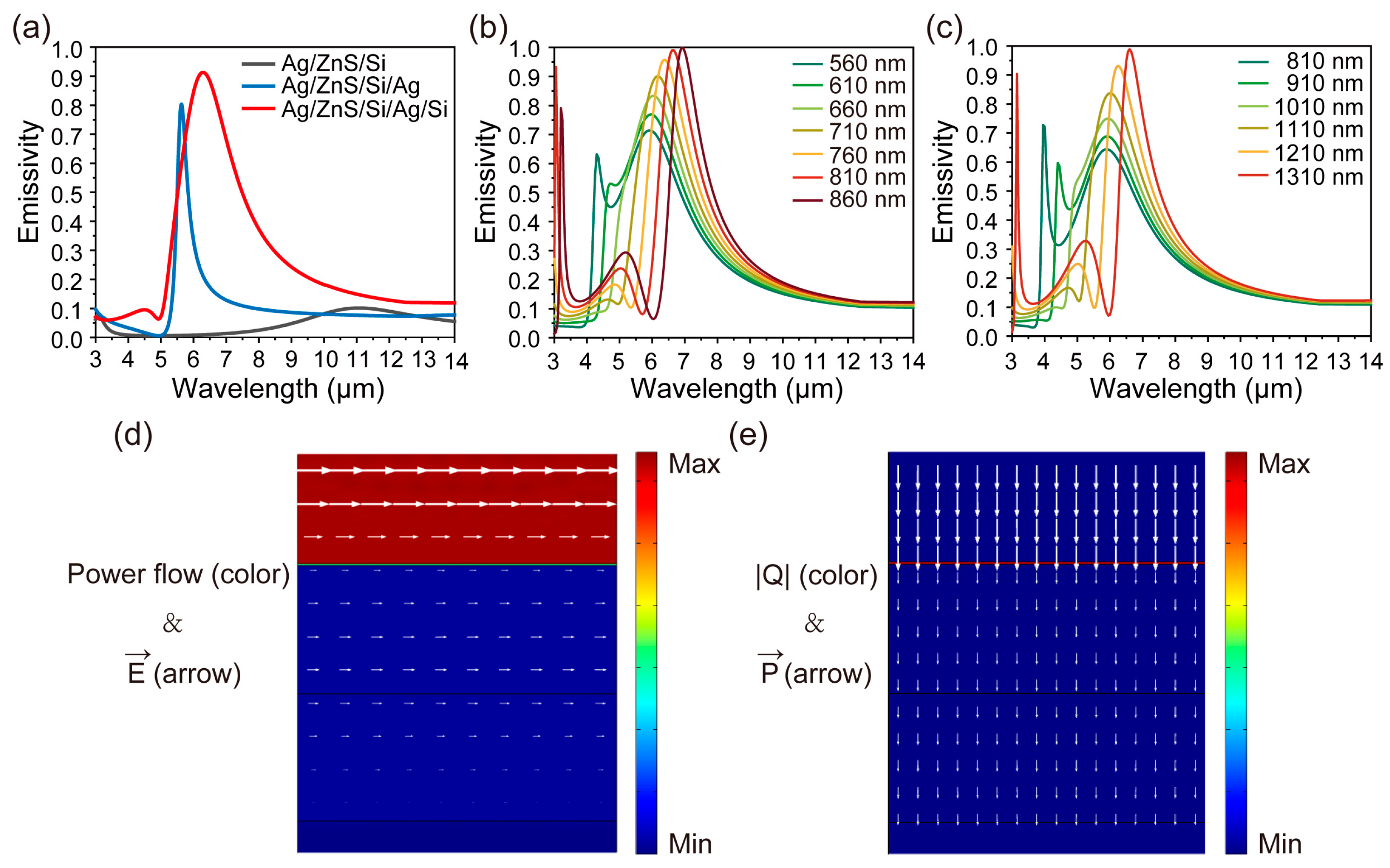
3.1. Structural Design and Mechanism
3.2. Experimental Demonstration and Radiative Cooling Performance
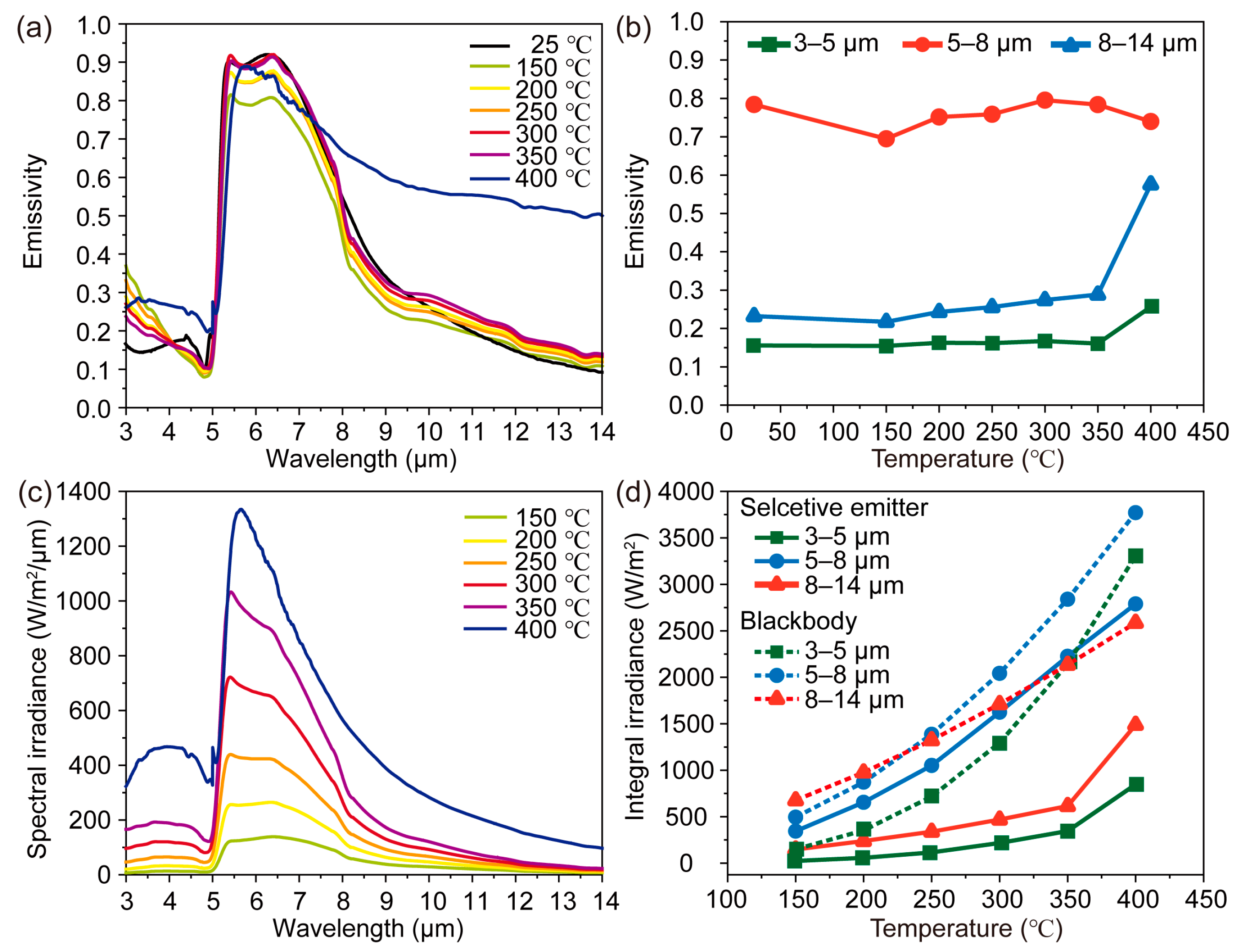
3.2.1. The Infrared Emissivity and Radiation Intensity of Selective Thermal Emitter
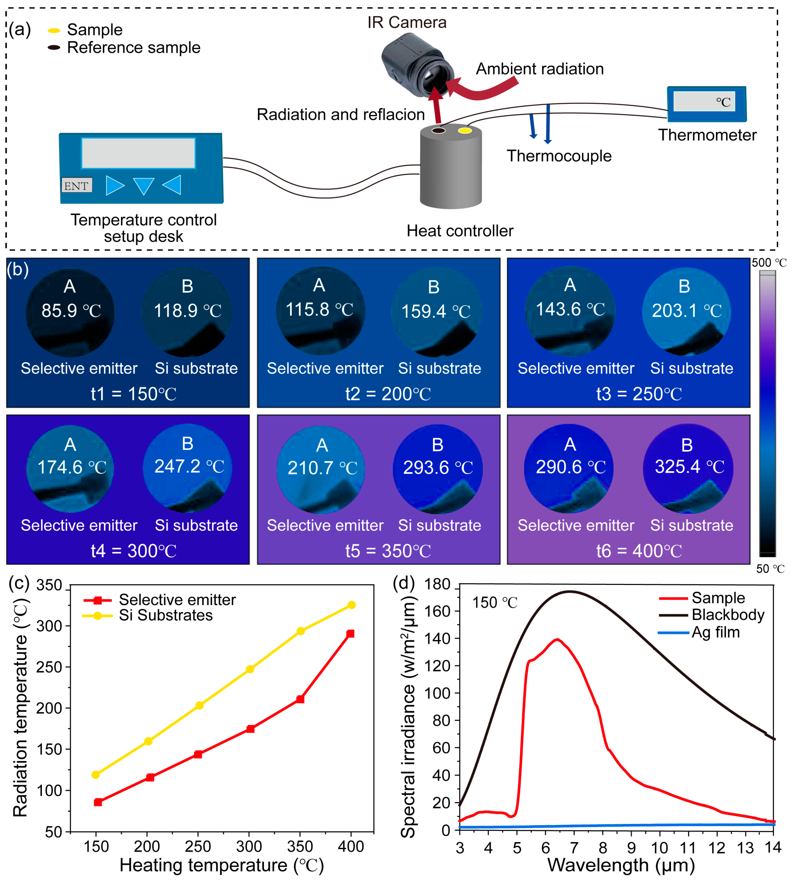
3.2.2. Infrared Camouflage Demonstration of the Selective Thermal Emitter
4. Conclusions
Supplementary Materials
Author Contributions
Funding
Institutional Review Board Statement
Informed Consent Statement
Data Availability Statement
Conflicts of Interest
References
- Li, Z.; Chen, Q.; Song, Y.; Zhu, B.; Zhu, J. Fundamentals, Materials, and Applications for Daytime Radiative Cooling. Adv. Mater. Technol. 2020, 5, 1901007. [Google Scholar] [CrossRef]
- Basu, S.; Zhang, Z.M.; Fu, C.J. Review of near-field thermal radiation and its application to energy conversion. Int. J. Energy Res. 2009, 33, 1203–1232. [Google Scholar] [CrossRef]
- Gui, B.; Wang, J.; Lu, X.; Zhu, Y.; Zhang, L.; Feng, M.; Huang, W.; Wang, J.; Ma, H.; Qu, S. Spectrally-switchable infrared selective emitters for adaptive camouflage. Infrared Phys. Technol. 2022, 126, 104363. [Google Scholar] [CrossRef]
- Li, T.; Zhai, Y.; He, S.; Gan, W.; Wei, Z.; Heidarinejad, M.; Dalgo, D.; Mi, R.; Zhao, X.; Song, J.; et al. A radiative cooling structural material. Science 2019, 364, 760–763. [Google Scholar] [CrossRef] [PubMed]
- Li, Y.; Lin, C.; Zhou, D.; An, Y.; Li, D.; Chi, C.; Huang, H.; Yang, S.; Tso, C.Y.; Chao, C.Y.J.N.E. Scalable all-ceramic nanofilms as highly efficient and thermally stable selective solar absorbers. Nano Energy 2019, 64, 103947. [Google Scholar] [CrossRef]
- Ding, D.; He, X.; Liang, S.; Wei, W.; Ding, S. Porous Nanostructured Composite Film for Visible-to-Infrared Camouflage with Thermal Management. ACS Appl. Mater. Interfaces 2022, 14, 24690–24696. [Google Scholar] [CrossRef]
- Zhu, H.; Li, Q.; Tao, C.; Hong, Y.; Xu, Z.; Shen, W.; Kaur, S.; Ghosh, P.; Qiu, M. Multispectral camouflage for infrared, visible, lasers and microwave with radiative cooling. Nat. Commun. 2021, 12, 1805. [Google Scholar] [CrossRef] [PubMed]
- Huang, J.; Wang, Y.; Yuan, L.; Huang, C.; Liao, J.; Ji, C.; Luo, X. Large-Area and Flexible Plasmonic Metasurface for Laser–Infrared Compatible Camouflage. Laser Photonics Rev. 2022, 17, 2200616. [Google Scholar] [CrossRef]
- Chandra, S.; Franklin, D.; Cozart, J.; Safaei, A.; Chanda, D. Adaptive Multispectral Infrared Camouflage. ACS Photonics 2018, 5, 4513–4519. [Google Scholar] [CrossRef]
- Kang, D.; Kim, Y.; Kim, C.; Lee, M. Highly Flexible Infrared Emitter with Spatially Controlled Emissivity for Optical Security. Adv. Mater. Technol. 2023, 8, 2200808. [Google Scholar] [CrossRef]
- Fu, C.; Zhang, Z.M. Thermal radiative properties of metamaterials and other nanostructured materials: A review. Front. Energy Power Eng. China 2009, 3, 11–26. [Google Scholar] [CrossRef]
- Kim, J.; Park, C.; Hahn, J.W. Metal–Semiconductor–Metal Metasurface for Multiband Infrared Stealth Technology Using Camouflage Color Pattern in Visible Range. Adv. Opt. Mater. 2022, 10, 2101930. [Google Scholar] [CrossRef]
- Lee, N.; Lim, J.S.; Chang, I.; Bae, H.M.; Nam, J.; Cho, H.H. Flexible Assembled Metamaterials for Infrared and Microwave Camouflage. Adv. Opt. Mater. 2022, 10, 2200448. [Google Scholar] [CrossRef]
- Shim, H.B.; Han, K.; Song, J.; Hahn, J.W. A Multispectral Single-Layer Frequency Selective Surface Absorber for Infrared and Millimeter Wave Selective Bi-Stealth. Adv. Opt. Mater. 2022, 10, 2102107. [Google Scholar] [CrossRef]
- Lee, N.; Yoon, B.; Kim, T.; Bae, J.Y.; Lim, J.S.; Chang, I.; Cho, H.H. Multiple Resonance Metamaterial Emitter for Deception of Infrared Emission with Enhanced Energy Dissipation. ACS Appl. Mater. Interfaces 2020, 12, 8862–8869. [Google Scholar] [CrossRef] [PubMed]
- Wang, L.; Yang, Y.; Tang, X.; Li, B.; Hu, Y.; Zhu, Y.; Yang, H. Combined multi-band infrared camouflage and thermal management via a simple multilayer structure design. Opt. Lett. 2021, 46, 5224–5227. [Google Scholar] [CrossRef] [PubMed]
- Zhang, L.; Wang, J.; Lou, J.; Zhu, Y.; Gui, B.; Feng, M.; Wang, J.; Qu, S. A thermally robust and optically transparent infrared selective emitter for compatible camouflage. J. Mater. Chem. C 2021, 9, 15018–15025. [Google Scholar] [CrossRef]
- Yu, K.; Zhang, W.; Qian, M.; Shen, P.; Liu, Y. Multiband metamaterial emitters for infrared and laser compatible stealth with thermal management based on dissipative dielectrics. Photonics Res. 2023, 11, 290–298. [Google Scholar] [CrossRef]
- Peng, L.; Liu, D.; Cheng, H.; Zhou, S.; Zu, M. A Multilayer Film Based Selective Thermal Emitter for Infrared Stealth Technology. Adv. Opt. Mater. 2018, 6, 1801006. [Google Scholar] [CrossRef]
- Lee, J.H.; Lee, J.C.W.; Leung, W.; Li, M.; Constant, K.; Chan, C.T.; Ho, K.M.J.A.M. Polarization engineering of thermal radiation using metallic photonic crystals. Adv. Mater. 2008, 20, 3244–3247. [Google Scholar] [CrossRef]
- Arnold, C.; Marquier, F.; Garin, M.; Pardo, F.; Collin, S.; Bardou, N.; Pelouard, J.-L.; Greffet, J.-J. Coherent thermal infrared emission by two-dimensional silicon carbide gratings. Phys. Rev. B 2012, 86, 035316. [Google Scholar] [CrossRef]
- Zhu, H.; Li, Q.; Zheng, C.; Hong, Y.; Xu, Z.; Wang, H.; Shen, W.; Kaur, S.; Ghosh, P.; Qiu, M. High-temperature infrared camouflage with efficient thermal management. Light-Sci. Appl. 2020, 9, 60. [Google Scholar] [CrossRef] [PubMed]
- Lee, N.; Kim, T.; Lim, J.S.; Chang, I.; Cho, H.H. Metamaterial-Selective Emitter for Maximizing Infrared Camouflage Performance with Energy Dissipation. ACS Appl. Mater. Interfaces 2019, 11, 21250–21257. [Google Scholar] [CrossRef] [PubMed]
- Zhao, J.; Wang, Y.; Zhu, Y.; Zhang, W.; Yu, Y. Lithography-free flexible perfect broadband absorber in visible light based on an all-dielectric multilayer structure. Opt. Lett. 2020, 45, 5464–5467. [Google Scholar] [CrossRef]
- Zhang, W.; Shan, W.; Qian, M.; Liu, Y.; Yu, K. A Mo/Si multilayer film based selective thermal emitter for high-temperature infrared stealth application. Infrared Phys. Technol. 2023, 131, 104643. [Google Scholar] [CrossRef]
- Glaubitt, W.; Löbmann, P. Antireflective coatings prepared by sol–gel processing: Principles and applications. J. Eur. Ceram. Soc. 2012, 32, 2995–2999. [Google Scholar] [CrossRef]
- Feng, L.; Huo, P.; Liang, Y.; Xu, T. Photonic Metamaterial Absorbers: Morphology Engineering and Interdisciplinary Applications. Adv. Mater. 2020, 32, e1903787. [Google Scholar] [CrossRef]


Disclaimer/Publisher’s Note: The statements, opinions and data contained in all publications are solely those of the individual author(s) and contributor(s) and not of MDPI and/or the editor(s). MDPI and/or the editor(s) disclaim responsibility for any injury to people or property resulting from any ideas, methods, instructions or products referred to in the content. |
© 2023 by the authors. Licensee MDPI, Basel, Switzerland. This article is an open access article distributed under the terms and conditions of the Creative Commons Attribution (CC BY) license (https://creativecommons.org/licenses/by/4.0/).
Share and Cite
Qian, M.; Shi, Q.; Qin, L.; Huang, J.; Guo, C.; Liu, Y.; Yu, K. Fabrication of Selective Thermal Emitter with Multilayer Films for Mid-/Low-Temperature Infrared Stealth with Radiative Cooling. Photonics 2023, 10, 645. https://doi.org/10.3390/photonics10060645
Qian M, Shi Q, Qin L, Huang J, Guo C, Liu Y, Yu K. Fabrication of Selective Thermal Emitter with Multilayer Films for Mid-/Low-Temperature Infrared Stealth with Radiative Cooling. Photonics. 2023; 10(6):645. https://doi.org/10.3390/photonics10060645
Chicago/Turabian StyleQian, Mengdan, Qingqing Shi, Lin Qin, Jinlong Huang, Caixia Guo, Yufang Liu, and Kun Yu. 2023. "Fabrication of Selective Thermal Emitter with Multilayer Films for Mid-/Low-Temperature Infrared Stealth with Radiative Cooling" Photonics 10, no. 6: 645. https://doi.org/10.3390/photonics10060645
APA StyleQian, M., Shi, Q., Qin, L., Huang, J., Guo, C., Liu, Y., & Yu, K. (2023). Fabrication of Selective Thermal Emitter with Multilayer Films for Mid-/Low-Temperature Infrared Stealth with Radiative Cooling. Photonics, 10(6), 645. https://doi.org/10.3390/photonics10060645