Article

Impact of Device Topology on the Performance of High-Speed 1550 nm Wafer-Fused VCSELs

by
Andrey Babichev
1,*,
Sergey Blokhin
2,
Andrey Gladyshev
1,
Leonid Karachinsky
1,
Innokenty Novikov
1,
Alexey Blokhin
2,
Mikhail Bobrov
2,
Yakov Kovach
1,
Alexander Kuzmenkov
2,
Vladimir Nevedomsky
2,
Nikolay Maleev
2,
Evgenii Kolodeznyi
1,
Kirill Voropaev
3,
Alexey Vasilyev
2,
Victor Ustinov
4,
Anton Egorov
5,
Saiyi Han
6,
Si-Cong Tian
6,7 and
Dieter Bimberg
6,7
1
Institute of Advanced Data Transfer Systems, ITMO University, Saint Petersburg 197101, Russia
2
Ioffe Institute, Saint Petersburg 194021, Russia
3
Yaroslav-the-Wise Novgorod State University, Veliky Novgorod 173003, Russia
4
Submicron Heterostructures for Microelectronics Research and Engineering Center, Russian Academy of Sciences (RAS), Saint Petersburg 194021, Russia
5
Alferov University, Saint Petersburg 194021, Russia
6
Bimberg Chinese-German Center for Green Photonics, Changchun Institute of Optics, Fine Mechanics and Physics (CIOMP), Chinese Academy of Sciences (CAS), Changchun 130033, China
7
Center of Nanophotonics, Institute of Solid State Physics, Technische Universität Berlin, Berlin 10623, Germany
*
Author to whom correspondence should be addressed.
Photonics 2023, 10(6), 660; https://doi.org/10.3390/photonics10060660
Submission received: 26 April 2023 / Revised: 29 May 2023 / Accepted: 4 June 2023 / Published: 7 June 2023

Abstract

:
A detailed experimental analysis of the impact of device topology on the performance of 1550 nm VCSELs with an active region based on thin InGaAs/InAlGaAs quantum wells and a composite InAlGaAs buried tunnel junction is presented. The high-speed performance of the lasers with L-type device topology (with the largest double-mesa sizes) is mainly limited by electrical parasitics showing noticeable damping of the relaxation oscillations. For the S-type device topology (with the smallest double-mesa sizes), the decrease in the parasitic capacitance of the reverse-biased p+n-junction region outside the buried tunnel junction region allowed to raise the parasitic cutoff frequency up to 13–14 GHz. The key mechanism limiting the high-speed performance of such devices is thus the damping of the relaxation oscillations. VCSELs with S-type device topology demonstrate more than 13 GHz modulation bandwidth and up to 37 Gbps nonreturn-to-zero data transmission under back-to-back conditions at 20 °C.

1. Introduction

Near-infrared vertical-cavity surface-emitting lasers (VCSELs) are standard sources for short- to medium-range interconnects, starting from single-mode (SM) board-to-board (0.3–1 m distance) to multi-mode intra-datacenter ones (1–500 m) [1]. For distances above 500 m and a bit error rate (BER) of 10−12, the power penalty due to modal and chromatic dispersion and mode partition noise, being typical for multi-mode VCSELs [2], becomes prohibitive [3]. Hyper datacenters are typical examples for using SM fibers for short distances to be supported by Wavelength Division Multiplexing (WDM) [4]. Long-wavelength (LW or short-wavelength infrared, SWIR) VCSELs allow to appreciably increase the distance covered by SM fibers [4] in the next generation of datacenters [5]. C-band VCSELs have the potential for 50 Gbps non-return-to-zero (NRZ) operation and show low latency. The power consumption of both NRZ and four-level Pulse Amplitude Modulation (PAM4) is lower as compared to that of DFB-lasers operating at the same wavelength [5]. C-band VCSELs can support 200 GbE operation [4]. In addition, LW VCSELs are very attractive for Spatial Division Multiplexing (SDM) based on multicore fibers (MCF) or few-mode fibers (FMF) [6,7,8].
The development of LW VCSELs is challenging due to critical limitations inherent to InAlGaAsP/InP and InAlGaAs/GaAs material systems. The main problems of monolithic (grown in a single epitaxial process) GaAs-based VCSELs are the lack of active regions, providing efficient radiative recombination in the targeted spectral range while maintaining a pseudomorphic growth mode, and an abrupt increase in free-carrier absorption as the wavelength increases. At the same time, the small refractive index contrast and low thermal conductivity of ternary and quaternary solid alloys lattice-matched to InP used in the distributed Bragg reflectors (DBRs) as well as the ineffective current confinement (air-gap aperture) are key problems of monolithic InP-based LW VCSELs. This high thermal resistance impairs the heat removal from the active region and leads to a rapid increase in the laser internal temperature. As a result, the poor temperature stability of monolithic 1550 nm InP-based VCSELs limits not only the maximum output power (about 1.6 mW at 20 °C) but also the high-speed performance (about 4 GHz) as well [9].
Today, the creation of high-speed 1550 nm VCSELs is related to two major technologies. The first one is based on InP-based active regions along with specific hybrid (metal-dielectric) DBRs, e.g., developed by the TUM/Vertilas team [10]. The second one is wafer-fused VCSELs. By this technology, pioneered by the ETH team, AlGaAs/GaAs-based DBRs with InP-based active regions are fused. The second approach allows realizing reliable LW VCSELs, satisfying the GR-468-CORE Telcordia qualification test [11]. In addition, high-contrast gratings (HCG) and micro-electro-mechanical system (MEMS) technologies to create 1550 nm VCSELs were developed [12,13,14,15].
Using the first technology, by replacing only one semiconductor InP-based DBR by a dielectric mirror integrated with a Au-heatsink, a −3 dB modulation bandwidth as large as 12 GHz at 25 °C and 10 GHz at 85 °C [16] was achieved. Open eyes of 25 Gbps at 20 °C and error-free data transmission up to 85 °C at 12.5 Gbps using NRZ signal modulation were demonstrated [17]. This type of VCSEL [18] presents an interesting alternative for creating large monolithic VCSELs arrays with high power (in the watt regime). In fact, recently, Vertilas announced SWIR VCSEL arrays (800 emitters) that emit 8 W of quasi-continuous power [19,20] suitable for eye-safe 3D sensing applications, such as face recognition in mobile phones or illumination.
Using short-cavity concepts (vertical microcavity design with two dielectric mirrors) made it possible to increase the modulation frequency of a 5 μm device to 17 GHz with a maximum output power of 3.5 mW [21]. Minimizing the volume of the mode to increase the D-factor (by reducing the optical cavity length and BTJ size) and reducing the parasitic capacitance of the reverse-biased p-n junction to increase the parasitic frequency cutoff (by applying the double-mesa structure and reducing the size of the mesa-containing BTJ) made it possible to demonstrate a 23 GHz [4,22,23,24,25,26,27] small-signal modulation bandwidth and 50 Gbps data transmission speed in a back-to-back (BTB) configuration without equalization or forward error correction [24]. The maximum SM output power (with a side mode suppression ratio of 40–45 dB) is about 1.6–3.0 mW for VCSELs with 3–4 BTJs [24,26,27,28]. The minimum DC power consumption is below 10 mW [24,29] due to the low differential resistance (~60 Ohm) and ultra-low threshold current (~1 mA for 4 μm buried tunnel junction devices). The 40 Gbps monolithic Coarse Wavelength Division Multiplexing (CWDM) C-band VCSEL arrays enable multicore, multi-level WDM for terabit board-to-board and rack-to-rack parallel optics (terabit-capacity active optical cable) [30]. To date, the total data throughput of 700 Gbps across a 7-core fiber is demonstrated for 20 GHz modulation bandwidth short-cavity VCSELs [31]. It should also be noted that a record SM output power of up to 8 mW has been demonstrated for larger (7 μm) BTJ diameters by insertion of mode-selective mirror losses and inhibition of spatial hole burning [32]. However, this approach is associated with strong deterioration of the modulation bandwidth due to the increase in the mode volume.
Wafer-fused VCSELs demonstrate large single-mode output power (≥6 mW at 20 °C) [33,34,35]. The modest high-speed performance of 1550 nm range WF VCSELs [34,35,36] is noticeably inferior to short-cavity VCSELs fabricated by the TUM/Vertilas team. It is related to the long cavity (~3λ) as well as the device topology inherent to short-cavity VCSELs with minimized mode volume. The change from a semiconductor DBR design to a dielectric/metal mirror allows the TUM/Vertilas team to reduce the active volume by a factor of 5 [21,37]. The differential gain is increased by enhancing the strain-induced mismatch.
In this paper, we provide a study of continuous-wave (CW) and dynamic characteristics of 1550 nm SM VCSELs, fabricated by wafer fusion of molecular-beam epitaxy (MBE)-grown structures. The same static and modulation performances as compared to previous records for WF metalorganic vapor-phase epitaxy (MOVPE)-grown VCSELs are demonstrated for large-type device topology. Optimization of device topology as well as structure design allows us to reach modulation bandwidths of 13 GHz and 37 Gbps data transmission rate (in BTB configuration for NRZ modulation) at room temperature.

2. VCSEL Structure and Fabrication

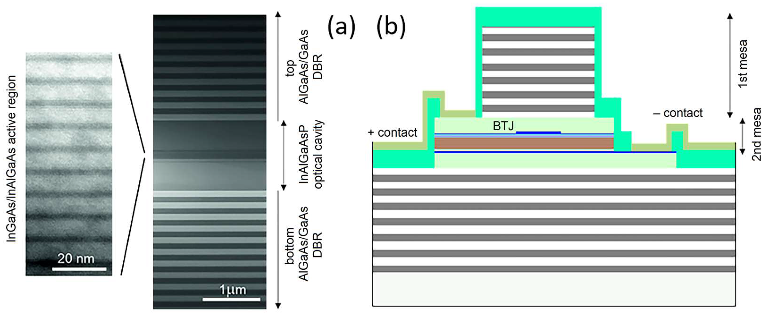
Undoped DBRs consisting of 22.5 and 35.5 pairs of Al0.9Ga0.1As/GaAs layers are used to confine an InAlGaAs/InP optical cavity with the length of 2.5λ. The optical cavity and DBR structures were grown by MBE on a Riber 49 mass production 4-inch system at Connector Optics LLC. We excluded using an n-InGaAsP layer due to possible problems with the reliable formation of ohmic contacts and the resulting additional potential barriers for carriers, which might lead to higher operating voltages and an increased temperature dependence of the current–voltage characteristics [38]. The longitudinal distribution of electromagnetic field intensity as well as the schematic cross-section of the microcavity region are presented in Figure 1. We used 10 of the 2.4 nm thick compressively strained In0.74Ga0.26As QWs grown with 1.44% lattice mismatch, ε, separated by 7 nm thick In0.53Al0.16Ga0.31As barrier layers lattice-matched (ε = 0.02%) to InP as the active region. It should be noted that for the MOVPE-grown 1550 nm WF VCSEL, tensile-strained barriers (ε = −0.8%) were previously used together with compressively strained thick InAlGaAs QWs (ε = 1.0%) [34] to compensate the total stress of the active region. The optical cavity and DBR thicknesses were chosen such that the cavity resonance was shifted to a longer wavelength by ~20–30 nm relative to the active region gain peak (so-called gain-to-cavity detuning, GCD). Previously, it was shown that small GCD allows one to increase the D-factor by better matching the differential gain peak in respect to the gain peak [28].
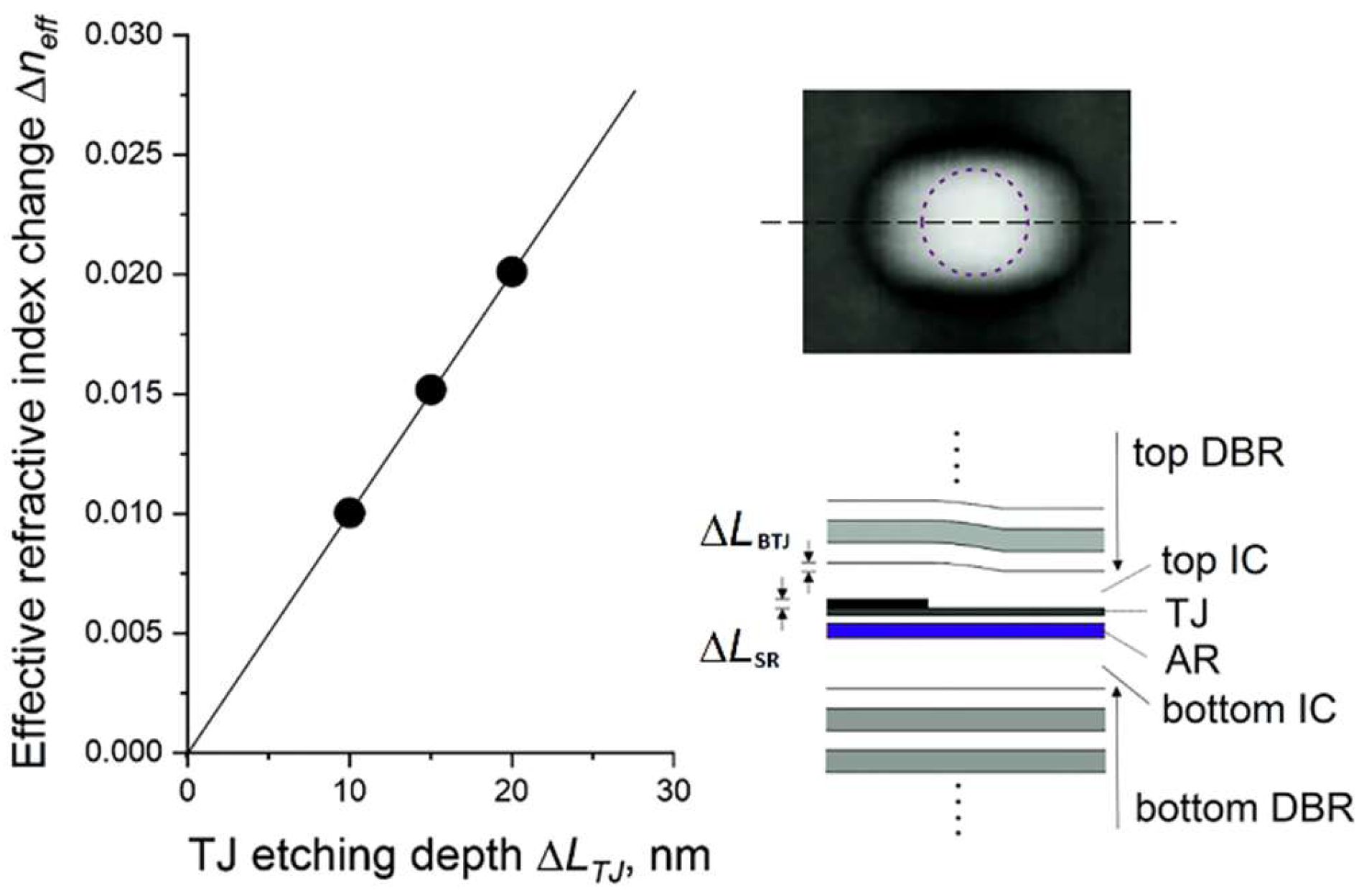
Buried tunnel junctions (BTJs) are used for transverse current/optical confinement. Usually, both for MOVPE- and MBE-grown 1550 nm VCSELs, n+/p+ AlGaInAs TJs are used to minimize internal optical losses [34,35]. For the MBE regrowth of TJs, a problem related to the oxidation of InAlGaAs surfaces during TJ mesa etching occurs. In general, hydrogen cleaning procedures [40,41] can resolve this problem if an RF plasma source is installed into an MBE system providing atomic hydrogen. Here, we used our original composite (multi-component) In(Al)GaAs TJ (n++/p++/p++ 37 nm thick In0.53Ga0.47As/In0.53Ga0.47As/In0.53Al0.16Ga0.31As) aimed to eliminate the hydrogen cleaning process during the MBE regrowth of TJs. The success of n+GaInAs/p+AlGaInAs TJs for 1550 nm VCSELs was previously attributed to the Burstein–Moss effect in n+-InGaAs [31]. Using photolithography and wet etching of a surface relief the composite TJ is formed, which is a set of circular mesas with a well-controlled diameter and etching depth ΔLTJ. The surface relief of the TJ layer was overgrown by MBE with a top n-type IC layer with a modulated doping profile. The surface relief parameters provide a compromise between the small mode volume required to increase the VCSEL high-speed performance and a large single-mode output power. In contrast to MOVPE growth [42], there is no planarization of the surface relief of the TJ during the MBE overgrowth process; thus, the height difference of the overgrown surface persists ΔLSR and coincides with the initial etching depths of the TJ layers ΔLTJ. Calculations within the effective refractive index model [43], presented in Figure 2, indicate that even at relatively small etching depths ΔLTJ of the composite TJ, a stronger lateral waveguide effect (effective refractive index contrast Δneff) is realized than for the case of near-IR oxide-confined (In)AlGaAs/GaAs VCSELs [44]. This fact significantly limits the size of the BTJ mesa, at which stable SM lasing can be realized for LW VCSELs. However, an atomic force microscopy (AFM) analysis (cf. Figure 2) shows an increase in the lateral sizes of the surface relief (about 1.5–2.0 times), accompanied by a lateral smoothing of the interface with the height difference after the TJ regrowth. As a result, an efficient waveguide with a gradient refractive index profile is formed, which makes it possible to significantly reduce the optical confinement factor (Γ-factor) for high-order modes. This reduction contributes to SM lasing at larger BTJ sizes due to an increase in the difference in the modal gain between the fundamental mode and high-order modes [45]. However, for small diameters of the BTJ, it is also necessary to consider the drop in the Γ-factor for the fundamental mode, which is accompanied by an increase in the level of optical losses in the non-pumped peripheral part of the active region. As a compromise, we formed circular mesas with a diameter of 6 μm and an etching depth of ~20 nm. The choice of the doping level of the n-InP overgrowth layer is associated with the search for a compromise between low electrical resistance to reduce the effect of self-heating, an increase in the VCSEL energy efficiency, and a low parasitic capacitance Cp of the reverse-biased p+n-junction region outside the BTJ mesa to improve the parasitic cutoff frequency and thus laser dynamics. The series resistance Rs describing the longitudinal current flow through the BTJ region is predominantly determined by the highly resistive p-InAlAs emitter. At the same time, the spreading resistance Rsp, which considers the lateral current flow through IC-layers, depends on the electrical resistance of the n-InP layers. The capacitance Cp is the space-charge capacitance arising between the p++-InGaAs and the heavily doped n-InP contact layer and depends on the donor concentration of the overgrown InP and the bias voltage [46]. For an average doping level of 1 × 1018 cm−3 of the n-InP overgrown layer (excluding the area for a highly doped contact layer), the spreading resistance Rsp is about 30 Ohm, and the operating voltage does not exceed 2.5 V. However, the huge capacitance Cp (up to 1.5 pF) limits the parasitic cutoff frequency to several GHz. Reducing the n-InP layer doping down to 1 × 1017 cm−3 of the overgrowth contributes to an expansion of the space-charge region and consequently reduces the capacitance Cp [17]. This allows a significant boost of the modulation bandwidth for the short-cavity VCSEL design [24]. However, WF VCSELs are characterized by a more extended device topology, which, together with the need for precision etching, leads to a dramatic increase in spreading resistance Rsp. As a compromise, we reduced the doping level of the n-InP overgrown layer to 5 × 1017 cm−3 and exploited a different device topology.
The number of InGaAs QWs was increased from 7 to 10 to increase the modal gain. The total mechanical strain of the active region was increased by minimizing the barrier thickness (from 12 nm to 7 nm) and no strain compensating barriers were used. Although MBE allows one to reach a record pseudomorphic strain in QWs (up to 3.5% [47]), it is supported by tensile-strained barriers [48]. As a result, partial stress compensation in the active region is realized [49]. Such a large compressive strain in QWs is related to an increase in the Al mole fraction [50] and nonradiative Shockley–Read–Hall (SRH) recombination [51,52]. The latter authors decreased the QWs strain to 1.2–1.7% [28] and aimed to decrease the Al mole fraction and changed to use weakly (ε = −0.02%) tensile-strained (Al0.274Ga0.203In0.523As) barriers. Here, we decreased the compressive strain in relation to InAlGaAs QWs, and at the same time, we eliminated the SRH loss using quaternary InAlGaAs QWs.
The serial resistance as well as the selectivity in the wet etching of the mesa were increased by using the bottom n-InGaAs and top n-InP layers instead of the bottom n-InGaAsP and top n-InGaAsP contact layers.
Finally, we implemented a composite BTJ (n++/p++/p++ In0.53Ga0.47As/In0.53Ga0.47As/In0.53Al0.16Ga0.31As TJ) as compared to the previous n++/p++ In0.53Al0.20Ga0.27As TJ. The doping level of the n-InP overgrown layer was reduced, aiming to increase the modulation performance [48,53,54].
To summarize, the design of the WF VCSELs presented here shows some fundamental changes compared to previous MBE-grown 1550 nm WF VCSELs [35].
Scanning transmission electron microscopy (STEM) images of a WF VCSEL structure and a transmission electron microscopy (TEM) image of the active region are presented in Figure 3a. The TEM studies were carried out using a JEM-2100F transmission electron microscope with an accelerating voltage of 200 keV. The samples in the cross-sectional geometry were prepared using a standard method by cleaving the structure along (110) planes, the “face to face” gluing of 2 pieces (by epoxy resin), and the subsequent grinding of both (110) sides. At the final stage, the samples were thinned by Ar+ ions at energies of 3–4 keV at an incidence angle of 7 degrees (by Nanomill 1050). These structural studies were performed using equipment of the Joint Research Center “Materials science and characterization in advanced technology” (registration No.: 3317) of the Ioffe Institute. According to the TEM data, after double wafer fusion, no noticeable smearing of the heterointerfaces of the strained quantum wells in the active region was observed. In addition, no formation of dislocations and other extended defects, as well as air voids associated with fused interfaces, were detected. One can find the details about the VCSELs fabrication process in previous publications [35,42]. Figure 3b shows a schematic view of the device with the double-mesa structure.
The 1st mesa was formed by dry etching (inductively coupled plasma, ICP) the top DBR. The second one by two-step wet etching of the InAlGaAsP/InP cavity. Silicon nitride was used for insulation and as a protection/phase-matching layer deposited on the top DBR.
The ohmic contacts (Ti/Pt/Au) were formed by a standard lift-off process. A GSG contact configuration was used. Two types of devices with unequal mesa sizes (marked as L-type and S-type topologies) were fabricated and studied.
The sizes for L-type topology were similar to those used for our previous MBE-grown 1550 nm WF VCSEL design [35,39]: the diameter of the 1st mesa was chosen to be 20 μm, while the sizes of the 2nd mesa were chosen to be ~35 μm × 25 μm. In the case of the S-type topology, the mesa sizes were significantly smaller to provide less parasitic capacitance of the VCSELs, and the capacitance Cp increases with the mesa size. The diameter of the 1st mesa was 12 μm. The sizes of the 2nd mesa were lowered to ~22 μm × 17 μm. As a result, the parasitic capacitance Cp was decreased as compared to L-type topology. It should be noted that it is very difficult to separate the reverse-biased junction capacitance Cp from the forward-biased junction capacitance Cj, because they are connected in parallel. Thus, only the capacitance Cm, which includes both components (Cj and Cp), was estimated. Evaluating the capacitance Cm, we reconstructed the equivalent circuit (solution of the inverse problem from S11 data) in the frequency range up to 20 GHz. As a result, the substitution of L-type to S-type device topology revealed a drop in the Cm value from 1 pF to about 0.5 pF.
To summarize, the device topology as well as the structure design were modified compared to previously MBE-grown 1550 nm WF VCSELs [35] to improve the modulation performance and to keep the large output power.

3. Results and Discussion

3.1. Static Characteristics

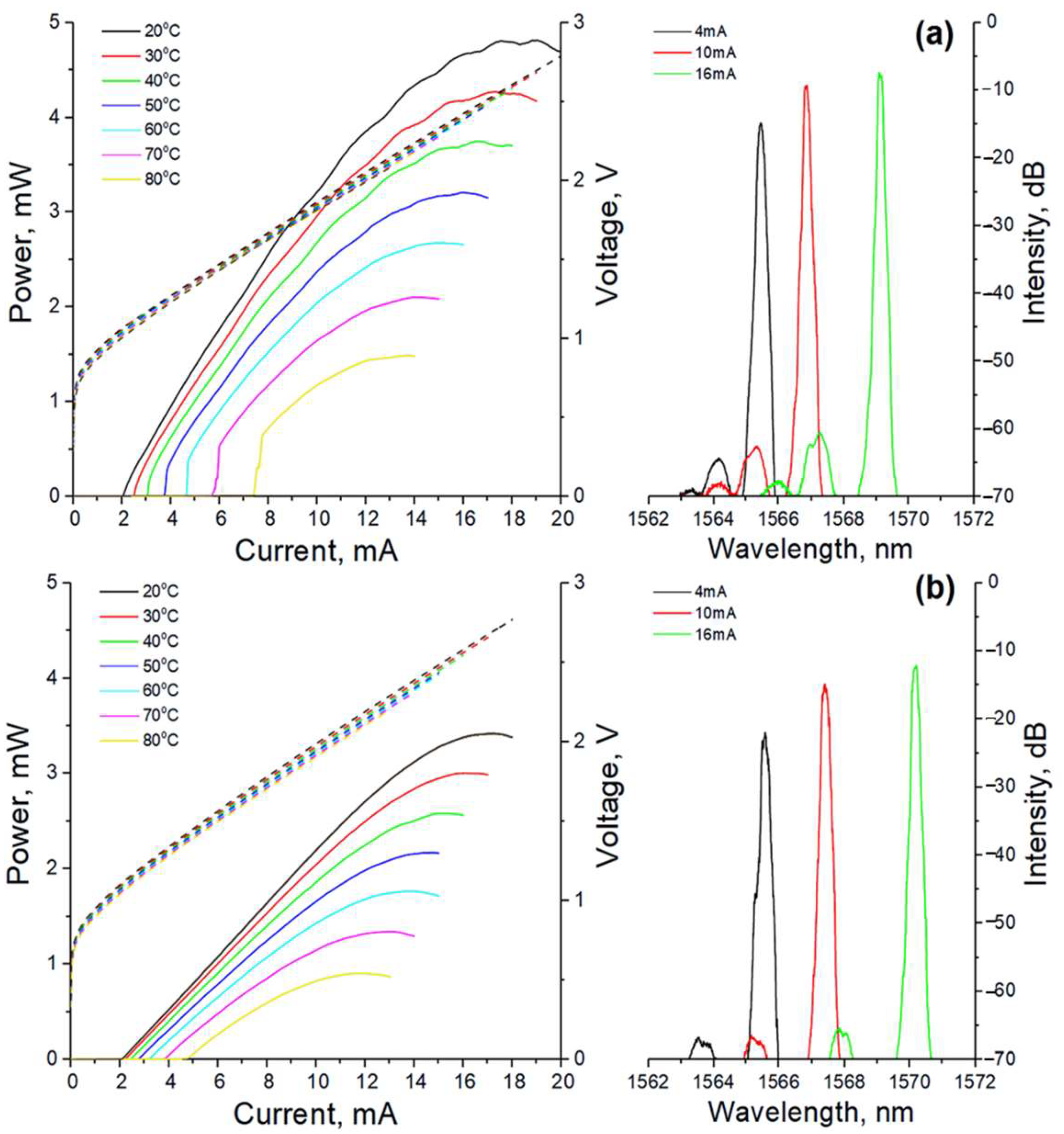
The CW light output power–current–voltage (LIV) characteristics were measured using a low-voltage Keithley 2400-LV sourcemeter and a calibrated photodiode Thorlabs SC122C. Figure 4a depicts the CW LIV characteristics for 1550 nm WF VCSELs with L-type device topology measured at various heatsink temperatures. At 20 °C, the lasers show a threshold current Ith less than 2 mA, with a slope efficiency (SE) of more than 0.45 W/A (equivalent to ~36%). The threshold voltage is 1.07 V. The maximum wall plug efficiency (WPE) is ~20%. The thermal rollover current Iroll is ~19 mA, which limits the maximum output power of ~4.8 mW. Increasing the BTJ size allows to increase the saturation current and the maximum output power, but at the same time the mode volume rises, which deteriorates the VCSELs modulation performance. In addition, the BTJ size is affected by the etching depth ΔLSR of the TJ: an increase in the ΔLSR value limits the maximal BTJ diameter for maintaining single-mode lasing. Thus, an increase in the BTJ size (up to 7–8 μm) in combination with the planarization effect during MOVPE overgrowth (to reduce the index guiding for higher-order transversal modes) made it possible to increase the SM output power of WF VCSELs to more than 6 mW [33,35]. An additional increase in the Iroll value can be achieved by increasing the thermal conductivity of the device. This depends not only on the size of the BTJ in our VSCELs but also the thermal conductivity of the bottom DBR and the bottom IC layer. The thermal heat management and planarization in the MOVPE overgrowth enabled the demonstration of 1550 nm range short-cavity VCSELs with an output power of 6.7 mW at a BTJ size of 5.5 µm [55]. An increase in the bottom AlGaAs/GaAs DBR thermal conductivity can be realized by increasing the Al content in the bottom DBR. Influences of AlGaAs heterointerface roughness on the VCSEL performance should be studied additionally. It should be noted that a further increase in output power requires the use of special methods for the creation of mode-selective mirror losses in order to provide SM emission for even larger BTJ diameters [32]. However, an increase in the BTJ size leads to an abrupt increase in the mode volume and a decrease in the modulation bandwidth.
The threshold current of L-type devices is comparable to that for MBE-grown wafer-fused 1550 nm VCSELs based on thin InGaAs QWs and n+/p+-In(Al)GaAs BTJs with a similar optical cavity design (Ith = 1.4 mA, SE = 0.51 W/A for an 8 μm BTJ diameter [35]), indicating a relatively low level of excess optical losses caused by optical absorption in the composite In(Al)GaAs BTJ. Note that WF VCSELs based on thick InAlGaAs QWs and an n+/p+-In(Al)GaAs BTJ fabricated by fusing MOVPE-grown wafers are noticeably inferior in terms of the threshold current for comparable mirror losses (Ith = 4.3 mA, SE = 0.44 W/A for 1490 nm WF VCSELs with a 7 μm BTJ diameter [34]; Ith = 4.1 mA, SE = 0.52 W/A for 1560 nm WF VCSELs with a 7 μm BTJ diameter; and Ith = 4.7 mA, SE = 0.46 W/A for 1580 nm WF VCSELs with a 7 μm BTJ diameter [33]).
It should be noted that short-cavity VCSELs with a single mesa and 3λ-long cavity (2.1 μm effective cavity length) demonstrate the threshold current and voltage are about 1 mA and 1 V. The rollover current is about 14 mA, which limits the maximum output power to ~3 mW for a 5 μm BTJ diameter [21]. The maximum WPE is about 20%. The change to a double-mesa design allows one to increase the output power (to about 4.5 mW) and WPE (to 28%) for the 5 μm BTJ diameter [28,56] by optimization mesa capacitance, thermal management, and output mirror losses (change from CaF2/ZnS to AlF3/ZnS pairs). The Iroll is ~17 mA.
Figure 4a, right, shows the lasing spectra at 20 °C. A Yokogawa AQ6370C-10 optical spectrum analyzer was used to measure the VCSELs emission spectra. The side mode suppression ratio (SMSR) exceeds 45 dB across the whole range of drive currents.
As the temperature rises to 70 °C, the maximum output power decreases to 2.1 mW, the threshold current increases to 6 mA, and the WPE is 9%. The maximum temperature where lasing occurred is 95 °C. Above 50 °C, an abrupt increase in the output power (so called LI kinks) appears as the drive current increases close to the lasing threshold. This effect is apparently associated with a saturable absorber effect in the unpumped parts of the active region (depending on the TJ etching depth), which previously was observed for 1550 nm WF VCSELs based on thin InGaAs QWs and an In(Al)GaAs TJ [39] and studied in detail for 1300 nm WF VCSELs based on an InAlGaAs superlattice and a composite In(Al)GaAs TJ [57].
The CW LIV characteristics for 1550 nm WF VCSELs with S-type device topology measured at various heatsink temperatures are shown in Figure 4b. The differential efficiency exceeds 0.27 W/A. The threshold current and voltage are 2.1 mA and 1.1 V. The largest WPE is about 11%. This decrease in differential efficiency restricts the maximum output power to 3.4 mW. The rollover current is 17 mA. The lower output power as compared to the L-type device topology can be explained by an increase in thermal resistance caused by the decrease in the second mesa size (increased self-heating). The reduction in the differential efficiency might be caused by an increase in light scattering in the top DBR, caused by the decrease in the first mesa size (excess in-plane optical losses). The lasing spectra measured at 20 °C demonstrate again single-mode lasing with an SMSR better than 45 dB for drive currents of 4–16 mA (cf. Figure 4b, right panel).
At 70 °C, the threshold current increases to 3.9 mA. As a result, the maximum output power and WPE values are limited to 1 mW and 6%, respectively. The maximum operating temperature of these devices is about 95 °C, in contrast to the L-type device topology.
One can see some wiggles in the LI curves for both device types (cf. Figure 4, left panel). Previously, a similar LI behavior was reported for 1300 nm WF VCSELs [58] as well as for 1570 nm WF VCSELs [59], but the reasons for this behavior were not discussed. It looks like mode hopping, but as was mentioned before, devices demonstrate an SM lasing in the current range studied. Moreover, polarization switching was also not observed. We suppose that this effect is related to the contribution of emission that has gone toward the substrate and is back-reflected at the lower semiconductor–air interface (in the case of using bilaterally polished GaAs substrates and/or after thinning the substrate), which is partially returned to the microcavity. A change in the external temperature or internal temperature (with increasing current) leads to a variation in the emission wavelength and the optical length of the external cavity that appears between the lower DBR and the substrate–air interface and, as a consequence, to a change in the output power.

3.2. Small-Signal Modulation

To analyze the electrical reflection (S11 parameter) and small-signal modulation response (S21 parameter), a Rohde & Schwarz ZVA 40 network analyzer and a 25 GHz New Focus 1434 photodetector were used. The VCSELs emission was coupled to a single-mode fiber (SMF) and detected by a Newport 1414–50 photodetector with a 25 GHz bandwidth. A 65 GHz Anritsu V255 bias tee and 40 GHz Picoprobe 40A-GSG-125-P RF probe were used to modulate the VCSELs current. A three-pole transfer function characterizing the laser response to sinusoidal modulation of the drive current at a given frequency f: H(f) ∝ fR2/(fR2f2 + jγ(f/2π))(1 + j(f/fp)), where fR is the relaxation resonance frequency, γ is the intrinsic damping factor, and fp is the parasitic cutoff frequency, was used to extract the key intrinsic parameters of the VCSEL.
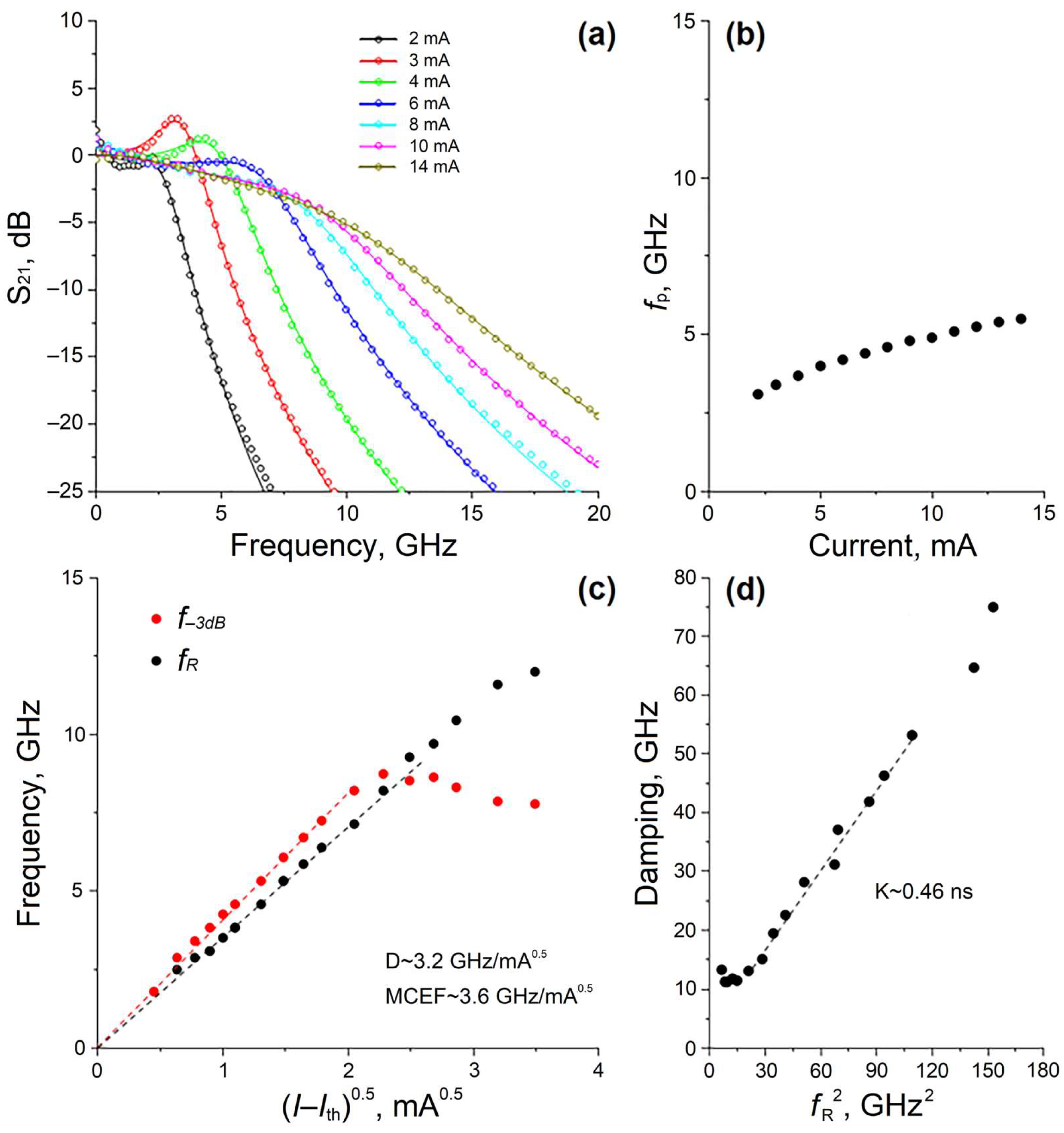
To minimize the error in recovering the laser intrinsic parameters from the S21 data, the cutoff frequency was independently determined from the VCSEL equivalent electrical circuit, and the parameters were extracted from the S11 data. Carrier injection through intracavity contacts forces to use an equivalent circuit with distributed parameters, which in turn makes the inverse problem nontrivial (convergence to different local minima). A slight increase in the number of lumped elements in the VCSEL equivalent circuit can potentially improve the quality of the experimental data fit [17]. Figure 5 depicts the results of the small-signal frequency analysis and the intrinsic modulation parameters determined from the measured S21(f) for lasers of L-type topology at 20 °C.
The −3 dB modulation bandwidth f−3dB is 6 GHz at a drive current of 4.5 mA and saturates at ~8 GHz (see Figure 5c). The modulation current efficiency, calculated by MCEF = f−3dB/(IIth)0.5, is 3.6 GHz/mA0.5. These results compare well with data for 1550 nm WF VCSELs based on thick InAlGaAs QWs and an In(Al)GaAs TJ [34]. If one increases the drive current above 6 mA, the fR value then exceeds the modulation bandwidth and yields around 12 GHz. The D-factor, determined as D = fR/(IIth)0.5, is 3.2 GHz/(mA)0.5.
Figure 5d shows the dependence of the intrinsic damping factor γ on the square of the relaxation resonance frequency fR2. Because the contribution of spontaneous emission to the lasing mode beyond the laser threshold and the effects of self-heating and gain saturation at large drive currents can be neglected at moderate photon densities, one can characterize the γ(fR2) dependences by linear fit: γ = K fR2 + γ0, where γ0 is the damping offset. As a result, the K-factor is determined to be 0.46 ns, which exceeds the K value for 1550 nm VCSELs based on thick InAlGaAs QWs and an InAlGaAs TJ [34] and 1550 nm WF VCSELs based on InGaAs QWs and an InAlGaAs TJ [36], showing similar differential efficiencies. The extracted large damping can be related to a combination of lower mirror loss and higher internal optical loss (to obtain comparable differential efficiency) and/or to higher gain compression in the thin InGaAs QW-based active region as compared to that for the thick InAlGaAs QW-based active region. The simulation of S11(f) shows that the main contribution to the parasitic cutoff frequency stems from the parasitic capacitance of the reverse-biased p+-n junction region (outside the BTJ region). As the forward voltage increases, the space-charge capacitance decreases, leading to an increase in the parasitic cutoff frequency and saturation at ~5 GHz at voltages above 1.6 V (see Figure 5b). In the case of the dominance of only electrical parasitics, the maximum achievable modulation bandwidth is more than 18 GHz (according to the expression f−3dB,parasitics = (2 + √3) fp), which significantly exceeds our experimental values of f−3dB. In the case of the dominance of thermal effects, the maximum achievable modulation bandwidth depends on the maximum attainable relaxation resonance frequency at drive currents near the thermal rollover, and should lie in the range 15–18 GHz (according to the expression f−3dB,thermal = √(1 + √2) fR). In the case of the dominance of only damping, the maximum achievable modulation bandwidth is determined by the K-factor, and also exceeds 18 GHz (according to the expression f−3dB,damping = 2π√2/K). Thus, we assume that the high-speed performance of the lasers in the L-type topology is limited by a combination of the first and third mechanism, which leads to a strong decrease in the resonance peak amplitude and overestimation of the intrinsic damping factor.
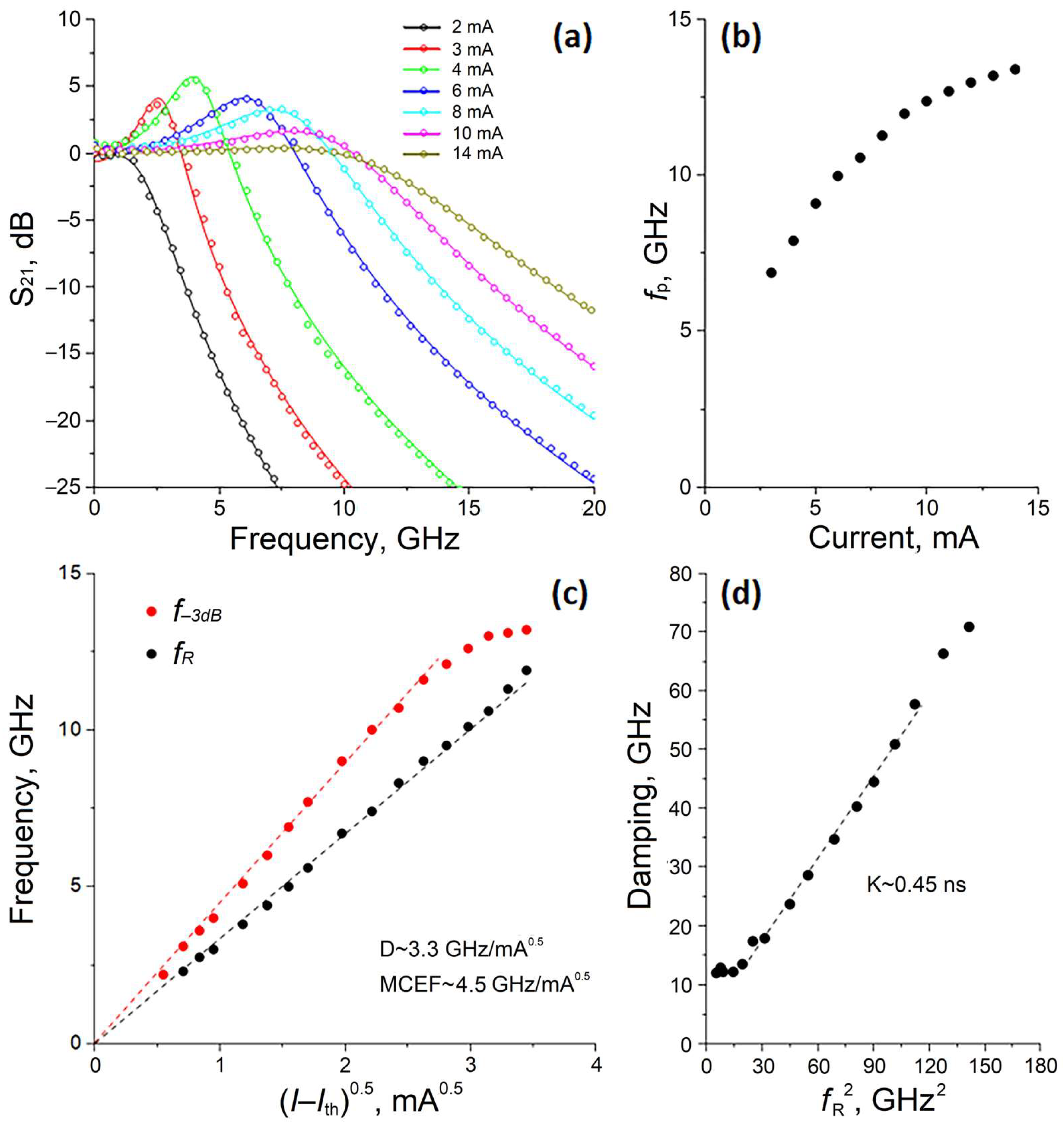
Lasers of S-type device topology are significantly different in their dynamic characteristics (see Figure 6a,b). Although the dependence of the relaxation resonance frequency fR on the square root of the drive current above the threshold shows a behavior similar to the lasers of L-type topology, an increase in the MCEF-factor up to 4.5 GHz/mA0.5 is observed (see Figure 6c). The D-factor is still about 3.3 GHz/mA0.5, which indicates the same differential gain for both device topologies for a fixed BTJ size. The K-factor is estimated to be 0.45 ns (see Figure 6d). The estimated f−3dB,damping and f−3dB,thermal values are 20 GHz and 18 GHz, respectively.
Modeling the S11(f) dependence revealed a strong drop in the parasitic capacitance of the reverse-biased p+n-junction region induced by a notable decrease in the second mesa size. As a result, the rise in the f−3dB,parasitics up to 13–15 GHz becomes possible which coincides to results for double-mesa short-cavity VCSELs [28]. As a result, the −3 dB modulation bandwidth f−3dB reaches 13 GHz at drive currents larger than 12 mA (see Figure 6c). This value of the modulation bandwidth is a record for 1550 nm VCSELs fabricated by the WF technology independent of the growth technique, type of active region, and TJ [34,35,36]. Our modulation bandwidth differs from the record value of the modulation bandwidth (22–23 GHz) for 1550 nm hybrid short-cavity VCSELs [4,22,23,27] mainly due to a smaller mode volume, higher parasitic frequency, and/or larger differential gain of the highly strained InAlGaAs QW-based active region in Refs. [4,23]. By carefully optimizing the doping profile of the n-InP overgrowth layer, we managed to find a variant of the intermediate device topology, leading to a parasitic frequency of more than 15 GHz, in which the first mesa does not significantly affect the device static characteristics. It should be noted that the mode volume minimization is associated with a decrease in the output power, so it is necessary to find a balance between high-speed performance and SM output power. A further increase in the modulation bandwidth seems to be associated with an increase in the resonant frequency and a decrease in damping.

3.3. Large-Signal Modulation

The modulation signal was generated by an SHF 12105A bit-pattern generator (BPG), amplified by an 11 dB amplifier (SHF 827 B) followed by a tunable 3 dB attenuator. A pseudorandom binary sequence with a word length of 27−1 was chosen. The emission of the VCSEL was coupled to the cleaved end of a 3 m SMF. An isolator was used to suppress the optical back reflections. A 33 GHz Tektronix DPO7OE1 optical probe (used for a VCSEL with L-type device topology) and a 42 GHz Thorlabs RXM42AF optical probe (used for a VCSEL with S-type device topology) were used to convert the optical signal to an electrical signal. The electrical signal was measured by a Tektronix 59 GHz real-time oscilloscope (DPO75902SX).
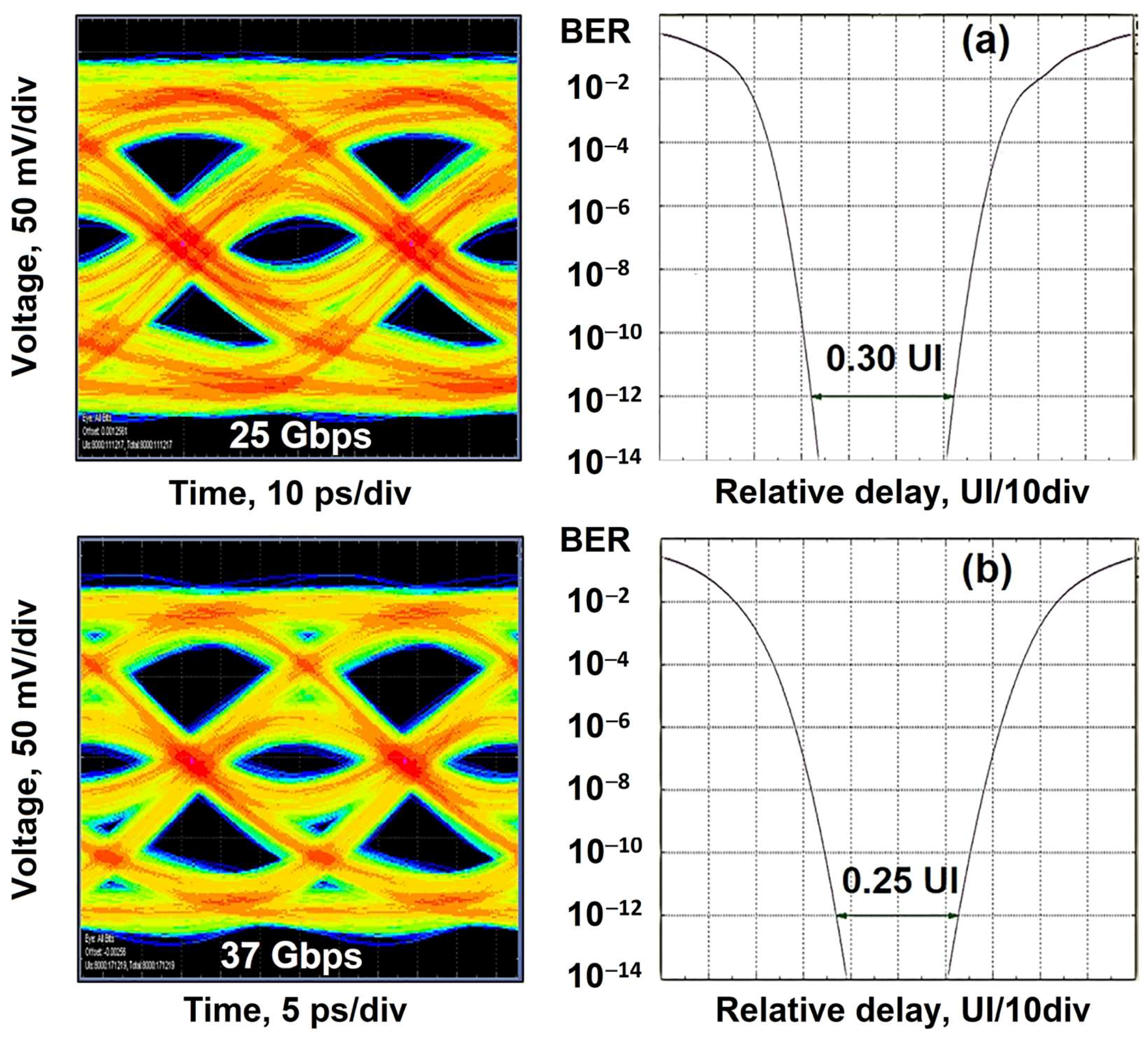
Clear open eye diagrams (Figure 7, left panel) were obtained for the 1550 nm WF VCSELs with L-type and S-type device topologies. The bit error ratio (BER) characteristics for crosstalk (bathtub curves) are shown on the right-hand side of Figure 7 and can be used to extract the jitter. By applying a 14 mA bias current and 300 mV modulation voltage, an NRZ data rate of 25 Gbps for an L-type VCSEL under BTB condition at 20 °C was achieved (left-hand side in Figure 7a). There is 0.3UI (12 ps) of eye opening and 70% total jitter (28 ps) at BER = 10−12 (right-hand side in Figure 7a). By applying a 16 mA bias current and 300 mV modulation voltage, an NRZ data rate of 37 Gbps for the S-type VCSEL under BTB condition at 20 °C was observed (left-hand side in Figure 7b), which is the largest data rate for 1550 nm WF VCSELs until now, to the best of our knowledge [34,35]. We observed a 0.25 UI (6.75 ps) of eye opening and 75% total jitter (20.3 ps) at BER = 10−12 (Figure 7b, right panel). The maximum bit rates shown here are expected to increase, once some changes to the measurement equipment have been made.

4. Conclusions

A detailed experimental analysis of the impact of device topology on the performance of 1550 nm VCSELs with an active region based on thin InGaAs/InAlGaAs quantum wells and a composite InAlGaAs BTJ was performed. The VCSELs structures were fabricated by wafer fusion of InP-based optical cavity structures with two AlGaAs/GaAs DBRs grown by MBE. Optimization of the composite InAlGaAs BTJ allowed us to find a balance between the mode volume and the single-mode output power. Moreover, doping adjustments of the overgrown n-InP layers help to find a compromise between low electrical resistance and high parasitic cutoff frequency. The high-speed performance of the lasers of L-type device topology (with the largest mesa sizes) is mainly limited by electrical parasitics and shows a noticeable damping of the relaxation oscillations. An analysis of S11(f) in the S-type device topology (with the smallest mesa sizes) leads to the conclusion that the key mechanism limiting our high-speed performance is the damping of the relaxation oscillations. The record values of the modulation bandwidth (13 GHz) and data transmission (37 Gbps in BTB configuration for NRZ direct modulation) are achieved at 20 °C for our 1550 nm WF VCSELs. The high output power and dynamic performance demonstrate the potential of our 1550 nm InGaAs QW-based WF VCSELs for large distance transmission systems (i.e., beyond ~1 km), where a high bit rate SM emission is required. Such lasers provide the basis for narrow WDM systems (with 5 nm channel spacing). Our monolithic VCSEL allows to realize high-capacity and compact short-reach optical interconnects for datacenters and arrays for 3D sensing and illumination applications. Another possible market of single-mode LWIR VCSELs is gas sensing tunable diode laser spectroscopy (TDLS).

Author Contributions

Conceptualization, S.B.; data curation, A.B. (Alexey Blokhin), A.K., A.G., A.V., K.V., M.B., S.H. and Y.K.; investigation, V.N., S.B. and S.-C.T.; writing—original draft, A.B. (Andrey Babichev), E.K., L.K., N.M. and S.B.; writing—review and editing, I.N., V.U. and D.B.; supervision, A.E. and D.B.; project administration, L.K.; funding acquisition, A.E. and D.B. All authors have read and agreed to the published version of the manuscript.

Funding

The authors from CAS acknowledge support by the National Key R&D Program of China (2021YFB2801000) for the large-signal modulation measurements of 1550 nm WF VCSELs. The authors from ITMO University acknowledge support in part by the Ministry of Science and Higher Education of the Russian Federation, project no. 2019-1442 (project reference number FSER-2020-0013) for the static characteristics measurements of 1550 nm WF VCSELs and in part by the Advanced Engineering Schools Federal Project for the small-signal modulation characteristics measurements of 1550 nm WF VCSELs. L. Karachinsky and S. Blokhin acknowledge the support of the CAS President’s international fellowship initiative grants No. 2023VTA0007 and No. 2023VTB0002 for the analysis of the static characteristics and small-signal modulation characteristics of 1550 nm WF VCSELs, respectively.

Data Availability Statement

Not applicable.

Conflicts of Interest

The authors declare no conflict of interest.

References

  1. Thraskias, C.A.; Lallas, E.N.; Neumann, N.; Schares, L.; Offrein, B.J.; Henker, R.; Plettemeier, D.; Ellinger, F.; Leuthold, J.; Tomkos, I. Survey of photonic and plasmonic interconnect technologies for intra-datacenter and high-performance computing communications. IEEE Commun. Surv. Tutor. 2018, 20, 2758–2783. [Google Scholar] [CrossRef] [Green Version]
  2. Ahmed, A.H.; Sharkia, A.; Casper, B.; Mirabbasi, S.; Shekhar, S. Silicon-photonics microring links for datacenters—Challenges and opportunities. IEEE J. Sel. Top. Quantum Electron. 2016, 22, 194–203. [Google Scholar] [CrossRef]
  3. Datacenters to Get a High Fiber Bandwidth Diet. Available online: https://www.nextplatform.com/2016/03/18/datacenters-get-high-fiber-bandwidth-diet/ (accessed on 14 April 2023).
  4. Kanakis, G.; Iliadis, N.; Soenen, W.; Moeneclaey, B.; Argyris, N.; Kalavrouziotis, D.; Spiga, S.; Bakopoulos, P.; Avramopoulos, H. High-speed VCSEL-based transceiver for 200 GbE short-reach intra-datacenter optical interconnects. Appl. Sci. 2019, 9, 2488. [Google Scholar] [CrossRef] [Green Version]
  5. Kuchta, D.M.; Huynh, T.N.; Doany, F.E.; Schares, L.; Baks, C.W.; Neumeyr, C.; Daly, A.; Kogel, B.; Rosskopf, J.; Ortsiefer, M. Error-free 56 Gb/s NRZ modulation of a 1530-nm VCSEL link. J. Lightwave Technol. 2016, 34, 3275–3282. [Google Scholar] [CrossRef]
  6. Zhang, L.; Chen, J.; Agrell, E.; Lin, R.; Wosinska, L. Enabling technologies for optical data center networks: Spatial division multiplexing. J. Lightwave Technol. 2020, 38, 18–30. [Google Scholar] [CrossRef]
  7. Liu, A.; Wolf, P.; Lott, J.A.; Bimberg, D. Vertical-cavity surface-emitting lasers for data communication and sensing. Photonics Res. 2019, 7, 121–136. [Google Scholar] [CrossRef]
  8. Charlier, J.C.; Krüger, S. Long-wavelength VCSELs ready to benefit 40/100-GbE modules. Lightwave 2023, 28, 2–7. Available online: https://www.lightwaveonline.com/optical-tech/article/16649511/longwavelengthvcsels-ready-to-benefit-40100gbe-module (accessed on 14 April 2023).
  9. Park, M.-R.; Kwon, O.-K.; Han, W.-S.; Lee, K.-H.; Park, S.-J.; Yoo, B.-S. All-epitaxial InAlGaAs-InP VCSELs in the 1.3–1.6-μm wavelength range for CWDM band applications. IEEE Photonics Technol. Lett. 2006, 18, 1717–1719. [Google Scholar] [CrossRef]
  10. Babichev, A.; Blokhin, S.; Kolodeznyi, E.; Karachinsky, L.; Novikov, I.; Egorov, A.; Tian, S.-C.; Bimberg, D. Long-wavelength VCSELs: Status and prospects. Photonics 2023, 10, 268. [Google Scholar] [CrossRef]
  11. Sirbu, A.; Suruceanu, G.; Iakovlev, V.; Mereuta, A.; Mickovic, Z.; Caliman, A.; Kapon, E. Reliability of 1310 nm wafer fused VCSELs. IEEE Photonics Technol. Lett. 2013, 25, 1555–1558. [Google Scholar] [CrossRef]
  12. Rao, Y.; Yang, W.; Chase, C.; Huang, M.C.; Worland, D.P.; Khaleghi, S.; Chitgarha, M.R.; Ziyadi, M.; Willner, A.E.; Chang-Hasnain, C.J. Long-wavelength VCSEL using high-contrast grating. IEEE J. Sel. Top. Quantum Electron. 2013, 19, 1701311. [Google Scholar] [CrossRef]
  13. Rao, Y.; Chase, C.; Huang, M.C.Y.; Khaleghi, S.; Chitgarha, M.R.; Ziyadi, M.; Worland, D.P.; Willner, A.E.; Chang-Hasnain, C.J. Tunable 1550-nm VCSEL using high contrast gratings. In Proceedings of the IEEE Photonics Conference 2012, Burlingame, CA, USA, 23–27 September 2012; pp. 864–865. [Google Scholar] [CrossRef]
  14. Paul, S.; Haidar, M.T.; Cesar, J.; Malekizandi, M.; Kögel, B.; Neumeyr, C.; Ortsiefer, M.; Küppers, F. Far-field, linewidth and thermal characteristics of a high-speed 1550-nm MEMS tunable VCSEL. Opt. Express 2016, 24, 13142–13156. [Google Scholar] [CrossRef] [PubMed]
  15. Zogal, K.H. MEMS weit abstimmbare VCSEL bei 1.55 μm und 1.95 μm. Ph.D. Thesis, Technische Universität, Darmstadt, Germany, 9 February 2017. Available online: https://tuprints.ulb.tu-darmstadt.de/6026/1/Dissertation_Zogal.pdf (accessed on 21 April 2023).
  16. Hofmann, W.; Müller, M.; Nadtochiy, A.; Meltzer, C.; Mutig, A.; Böhm, G.; Rosskopf, J.; Bimberg, D.; Amann, M.-C.; Chang-Hasnain, C. 22-Gb/s long wavelength VCSELs. Opt. Express 2009, 17, 17547–17554. [Google Scholar] [CrossRef] [PubMed] [Green Version]
  17. Hofmann, W. High-speed buried tunnel junction vertical-cavity surface-emitting lasers. IEEE Photonics J. 2010, 2, 802–815. [Google Scholar] [CrossRef]
  18. Dohle, R.; Henning, G.; Wallrodt, M.; Gréus, C.; Neumeyr, C. Advanced packaging technology for novel 1-dimensional and 2-dimensional VCSEL Arrays. IMAPSource Proceedings 2021, 1, 000265–000270. [Google Scholar] [CrossRef]
  19. VCSEL advancements power 3d sensing. Available online: https://www.photonics.com/Articles/VCSELs_Increase_Power_and_Wavelength_for_3D/a68069 (accessed on 29 May 2023).
  20. Vertilas GmbH InP long wavelength VCSELs. Available online: https://epic-assoc.com/wp-content/uploads/2021/12/Christian-Neumeyr-Vertilas.pdf (accessed on 29 May 2023).
  21. Muller, M.; Hofmann, W.; Grundl, T.; Horn, M.; Wolf, P.; Nagel, R.D.; Ronneberg, E.; Bohm, G.; Bimberg, D.; Amann, M.C. 1550-nm High-speed short-cavity VCSELs. IEEE J. Sel. Top. Quantum Electron. 2011, 17, 1158–1166. [Google Scholar] [CrossRef]
  22. Pang, X.; Van Kerrebrouck, J.; Ozolins, O.; Lin, R.; Udalcovs, A.; Zhang, L.; Spiga, S.; Amann, M.C.; Van Steenberge, G.; Gan, L.; et al. 7× 100 Gbps PAM-4 transmission over 1-km and 10-km single mode 7-core fiber using 1.5-μm SM-VCSEL. In Proceedings of the 2018 Optical Fiber Communications Conference and Exposition (OFC), San Diego, CA, USA, 11–15 March 2018; pp. 1–3. [Google Scholar] [CrossRef] [Green Version]
  23. Spiga, S.; Schoke, D.; Andrejew, A.; Müller, M.; Boehm, G.; Amann, M.-C. Single-mode 1.5-µm VCSELs with 22-GHz small-signal bandwidth. In OSA Technical Digest, Proceedings of the Optical Fiber Communication Conference 2016, Anaheim, CA, USA, 20–22 March 2016; Paper Tu3D.4; Optica Publishing Group: Washington, DC, USA, 2016. [Google Scholar] [CrossRef]
  24. Spiga, S.; Soenen, W.; Andrejew, A.; Schoke, D.M.; Yin, X.; Bauwelinck, J.; Boehm, G.; Amann, M.-C. Single-mode high-speed 1.5-μm VCSELs. J. Lightwave Technol. 2017, 35, 727–733. [Google Scholar] [CrossRef]
  25. Zhang, L.; Van Kerrebrouck, J.; Lin, R.; Pang, X.; Udalcovs, A.; Ozolins, O.; Spiga, S.; Amann, M.-C.; Van Steenberge, G.; Gan, L.; et al. Nonlinearity tolerant high-speed DMT transmission with 1.5-μm single-mode VCSEL and multi-core fibers for optical interconnects. J. Lightwave Technol. 2019, 37, 380–388. [Google Scholar] [CrossRef] [Green Version]
  26. Zhang, L.; Van Kerrebrouck, J.; Ozolins, O.; Lin, R.; Pang, X.; Udalcovs, A.; Spiga, S.; Amann, M.C.; Gan, L.; Tang, M.; et al. Experimental demonstration of 503.61-Gbit/s DMT over 10-km 7-core fiber with 1.5-μm SM-VCSEL for optical interconnects. In Proceedings of the 2018 European Conference on Optical Communication (ECOC), Rome, Italy, 23–27 September 2018. [Google Scholar] [CrossRef]
  27. Pang, X.; Van Kerrebrouck, J.; Ozolins, O.; Lin, R.; Udalcovs, A.; Zhang, L.; Spiga, S.; Amann, M.C.; Van Steenberge, G.; Gan, L.; et al. High-speed SDM interconnects with directly-modulated 1.5-μm VCSEL enabled by low-complexity signal processing techniques. In OSA Technical Digest, Proceedings of the Advanced Photonics 2018 (BGPP, IPR, NP, NOMA, Sensors, Networks, SPPCom, SOF), Signal Processing in Photonic Communications 2018, Zurich, Switzerland, 2–5 July 2018; Paper SpTh2G.4; Optica Publishing Group: Washington, DC, USA, 2018. [Google Scholar] [CrossRef] [Green Version]
  28. Spiga, S.; Schoke, D.; Andrejew, A.; Boehm, G.; Amann, M.C. Effect of cavity length, strain, and mesa capacitance on 1.5-μm VCSELs performance. J. Lightwave Technol. 2017, 35, 3130–3141. [Google Scholar] [CrossRef]
  29. Fabrega, J.M.; Vílchez, F.J.; Svaluto Moreolo, M.; Martínez, R.; Quispe, A.; Nadal, L.; Casellas, R.; Vilalta, R.; Muñoz, R.; Neumeyr, C.; et al. Experimental demonstration of a metro area network with terabit-capable sliceable bit-rate-variable transceivers using directly modulated VCSELs and coherent detection. J. Opt. Commun. Netw. 2023, 15, A103–A113. [Google Scholar] [CrossRef]
  30. Multi-Core, Multi-Level, DWM-Enabled Embedded Optical Engine for Terabit Board-to-Board and Rack-to-Rack Parallel Optics. Available online: https://cordis.europa.eu/docs/projects/cnect/8/318228/080/deliverables/002-MIRAGEshortpresentation.pdf (accessed on 29 May 2023).
  31. Van Kerrebrouck, J.; Pang, X.; Ozolins, O.; Lin, R.; Udalcovs, A.; Zhang, L.; Li, H.; Spiga, S.; Amann, M.-C.; Gan, L.; et al. High-speed PAM4-based optical SDM interconnects with directly modulated long-wavelength VCSEL. J. Lightwave Technol. 2019, 37, 356–362. [Google Scholar] [CrossRef] [Green Version]
  32. Grundl, T.; Debernardi, P.; Muller, M.; Grasse, C.; Ebert, P.; Geiger, K.; Ortsiefer, M.; Bohm, G.; Meyer, R.; Amann, M.-C. Record Single-mode, high-power VCSELs by inhibition of spatial hole burning. IEEE J. Sel. Top. Quantum Electron. 2013, 19, 1700913. [Google Scholar] [CrossRef]
  33. Caliman, A.; Mereuta, A.; Suruceanu, G.; Iakovlev, V.; Sirbu, A.; Kapon, E. 8 mW fundamental mode output of wafer-fused VCSELs emitting in the 1550-nm band. Opt. Express 2011, 19, 16996. [Google Scholar] [CrossRef] [PubMed]
  34. Ellafi, D.; Iakovlev, V.; Sirbu, A.; Suruceanu, G.; Mickovic, Z.; Caliman, A.; Mereuta, A.; Kapon, E. Control of cavity lifetime of 1.5 µm wafer-fused VCSELs by digital mirror trimming. Opt. Express 2014, 22, 32180–32187. [Google Scholar] [CrossRef]
  35. Babichev, A.V.; Karachinsky, L.Y.; Novikov, I.I.; Gladyshev, A.G.; Blokhin, S.A.; Mikhailov, S.; Iakovlev, V.; Sirbu, A.; Stepniak, G.; Chorchos, L.; et al. 6-mW single-mode high-speed 1550-nm wafer-fused VCSELs for DWDM application. IEEE J. Quantum Electron. 2017, 53, 1–8. [Google Scholar] [CrossRef]
  36. Blokhin, S.A.; Bobrov, M.A.; Blokhin, A.A.; Kuzmenkov, A.G.; Maleev, N.A.; Ustinov, V.M.; Kolodeznyi, E.S.; Rochas, S.S.; Babichev, A.V.; Novikov, I.I.; et al. Influence of output optical losses on the dynamic characteristics of 1.55-μm wafer-fused vertical-cavity surface-emitting lasers. Semiconductors 2019, 53, 1104–1109. [Google Scholar] [CrossRef]
  37. Gruendl, T.; Mueller, M.; Amann, M.-C. New standards in high-speed and tunable long wavelength VCSELs. In Proceedings of the SPIE Photonics Europe, Brussels, Belgium, 16–19 April 2012; Volume 8432, p. 843203. [Google Scholar] [CrossRef]
  38. Blokhin, S.A.; Bobrov, M.A.; Maleev, N.A.; Blokhin, A.A.; Kuz’menkov, A.G.; Vasil’ev, A.P.; Rochas, S.S.; Gladyshev, A.G.; Babichev, A.V.; Novikov, I.I.; et al. A vertical-cavity surface-emitting laser for the 1.55-μm spectral range with tunnel junction based on n++-InGaAs/p++-InGaAs/p++-InAlGaAs layers. Tech. Phys. Lett. 2020, 46, 854–858. [Google Scholar] [CrossRef]
  39. Babichev, A.; Blokhin, S.; Gladyshev, A.; Karachinsky, L.; Novikov, I.; Blokhin, A.; Bobrov, M.; Maleev, N.; Andryushkin, V.; Kolodeznyi, E.; et al. Single-mode high-speed 1550 nm wafer fused VCSELs for narrow WDM systems. IEEE Photonics Technol. Lett. 2023, 35, 297–300. [Google Scholar] [CrossRef]
  40. Bell, G.R.; Kaijaks, N.S.; Dixon, R.J.; McConville, C.F. Atomic hydrogen cleaning of polar III–V semiconductor surfaces. Surf. Sci. 1998, 401, 125–137. [Google Scholar] [CrossRef]
  41. Seidel, U.; Schimper, H.-J.; Kollonitsch, Z.; Möller, K.; Schwarzburg, K.; Hannappel, T. Growth of an InGaAs/GaAsSb tunnel junction for an InP-based low band gap tandem solar cell. J. Cryst. Growth 2007, 298, 777–781. [Google Scholar] [CrossRef]
  42. Sirbu, A.; Iakovelv, V.; Mereuta, A.; Caliman, A.; Suruceanu, G.; Kapon, E. Wafer-fused heterostructures: Application to vertical cavity surface-emitting lasers emitting in the 1310 nm band. Semicond. Sci. Technol. 2010, 26, 014016. [Google Scholar] [CrossRef]
  43. Hadley, G.R. Effective index model for vertical-cavity surface-emitting lasers. Opt. Lett. 1995, 20, 1483–1485. [Google Scholar] [CrossRef] [PubMed]
  44. Michalzik, R. VCSELs: Fundamentals, Technology and Applications of Vertical-Cavity Surface-Emitting Lasers; Springer Series in Optical Sciences; Springer: Berlin, Germany, 2013; p. 560. [Google Scholar] [CrossRef]
  45. Blokhin, S.A.; Bobrov, M.A.; Blokhin, A.A.; Vasil’ev, A.P.; Kuz’menkov, A.G.; Maleev, N.A.; Rochas, S.S.; Gladyshev, A.G.; Babichev, A.V.; Novikov, I.I.; et al. The effect of a saturable absorber in long-wavelength vertical-cavity surface-emitting lasers fabricated by wafer fusion technology. Tech. Phys. Lett. 2020, 46, 1257–1262. [Google Scholar] [CrossRef]
  46. Sze, S.M.; Ng, K.K. Physics of Semiconductor Devices, 2nd ed.; John Wiley & Sons: Hoboken, NJ, USA, 2006; p. 832. [Google Scholar] [CrossRef] [Green Version]
  47. Spiga, S.; Schoke, D.; Andrejew, A.; Boehm, G.; Amann, M.-C. Enhancing the small-signal bandwidth of single-mode 1.5-μm VCSELs. In Proceedings of the 2016 IEEE Optical Interconnects Conference (OI), San Diego, CA, USA, 9–11 May 2016. [Google Scholar] [CrossRef]
  48. Amann, M.C.; Hofmann, W. InP-based long-wavelength VCSELs and VCSEL arrays. IEEE J. Sel. Top. Quantum Electron. 2009, 15, 861–868. [Google Scholar] [CrossRef]
  49. Maute, M.; Amann, M.C. Long-wavelength VCSELs. In Proceedings of the 16th IPRM. 2004 International Conference on Indium Phosphide and Related Materials, 2004, Kagoshima, Japan, 31 May–4 June 2004; pp. 695–699. [Google Scholar] [CrossRef]
  50. Spiga, S.; Amann, M.C. High-speed InP-based long-wavelength VCSELs. In Green Photonics and Electronics; Eisenstein, G., Bimberg, D., Eds.; Springer: Cham, Switzerland, 2017; Volume 3, pp. 17–35. [Google Scholar] [CrossRef]
  51. Grasse, C.; Mueller, M.; Gruendl, T.; Boehm, G.; Roenneberg, E.; Wiecha, P.; Rosskopf, J.; Ortsiefer, M.; Meyer, R.; Amann, M.C. AlGaInAsPSb-based high-speed short-cavity VCSEL with single-mode emission at 1.3 μm grown by MOVPE on InP substrate. J. Cryst. Growth 2013, 370, 217–220. [Google Scholar] [CrossRef]
  52. Müller, M.; Grasse, C.; Saller, K.; Gründl, T.; Böhm, G.; Ortsiefer, M.; Amann, M.C. 1.3 μm high-power short-cavity VCSELs for high-speed applications. In Proceedings of the Conference on Lasers and Electro-Optics 2012, San Jose, CA, USA, 6–11 May 2012; p. CW3N-2. [Google Scholar] [CrossRef]
  53. Hofmann, W. InP-Based Long-Wavelength VCSELs and VCSEL Arrays for High-Speed Optical Communication. Doktor-Ingenieurs Thesis, Technische Universität München, München, Germany, 26 January 2009. Available online: https://d-nb.info/999941925/34 (accessed on 14 April 2023).
  54. Muller, M.; Hofmann, W.; Bohm, G.; Amann, M.C. Short-cavity long-wavelength VCSELs with modulation bandwidths in excess of 15 GHz. IEEE Photonics Technol. Lett. 2009, 21, 1615–1617. [Google Scholar] [CrossRef]
  55. Meyer, R.; Meissner, P.; Amann, M.-C.; Zogal, K.; Nagel, R.D.; Gruendl, T.; Geiger, K.; Grasse, C.; Ortsiefer, M.; Mueller, M.; et al. High-Speed and high-power vertical-cavity surface-emitting lasers based on InP suitable for telecommunication and gas sensing. In Proceedings of SPIE, Proceedings of the SPIE Remote Sensing, Toulouse, France, 20–23 September 2010; Society of Photo-Optical Instrumentation Engineers (SPIE): Bellingham, WA, USA, 2010; Volume 7828, p. 782807. [Google Scholar] [CrossRef]
  56. Spiga, S.; Andrejew, A.; Boehm, G.; Amann, M.-C. Single-mode 1.5-µm VCSELs with small-signal bandwidth beyond 20 GHz. In Proceedings of the 2016 18th International Conference on Transparent Optical Networks (ICTON), Trento, Italy, 10–14 July 2016. [Google Scholar] [CrossRef]
  57. Blokhin, S.A.; Babichev, A.V.; Gladyshev, A.G.; Karachinsky, L.Y.; Novikov, I.I.; Blokhin, A.A.; Bobrov, M.A.; Maleev, N.A.; Andryushkin, V.V.; Denisov, D.V.; et al. High power single mode 1300-nm superlattice based VCSEL: Impact of the buried tunnel junction diameter on performance. IEEE J. Quantum Electron. 2022, 58, 2400115. [Google Scholar] [CrossRef]
  58. Lamothe, E. Analysis and Control of Optical Modes in VCSELs and VCSEL-Arrays. Ph.D. Thesis, EPFL, Lausanne, Switzerland, 1 November 2013. [Google Scholar] [CrossRef]
  59. Volet, N. Optical Mode Control in Long-Wavelength Vertical-Cavity Surface-Emitting Lasers. Ph.D. Thesis, EPFL, Lausanne, Switzerland, 4 April 2014. [Google Scholar] [CrossRef]
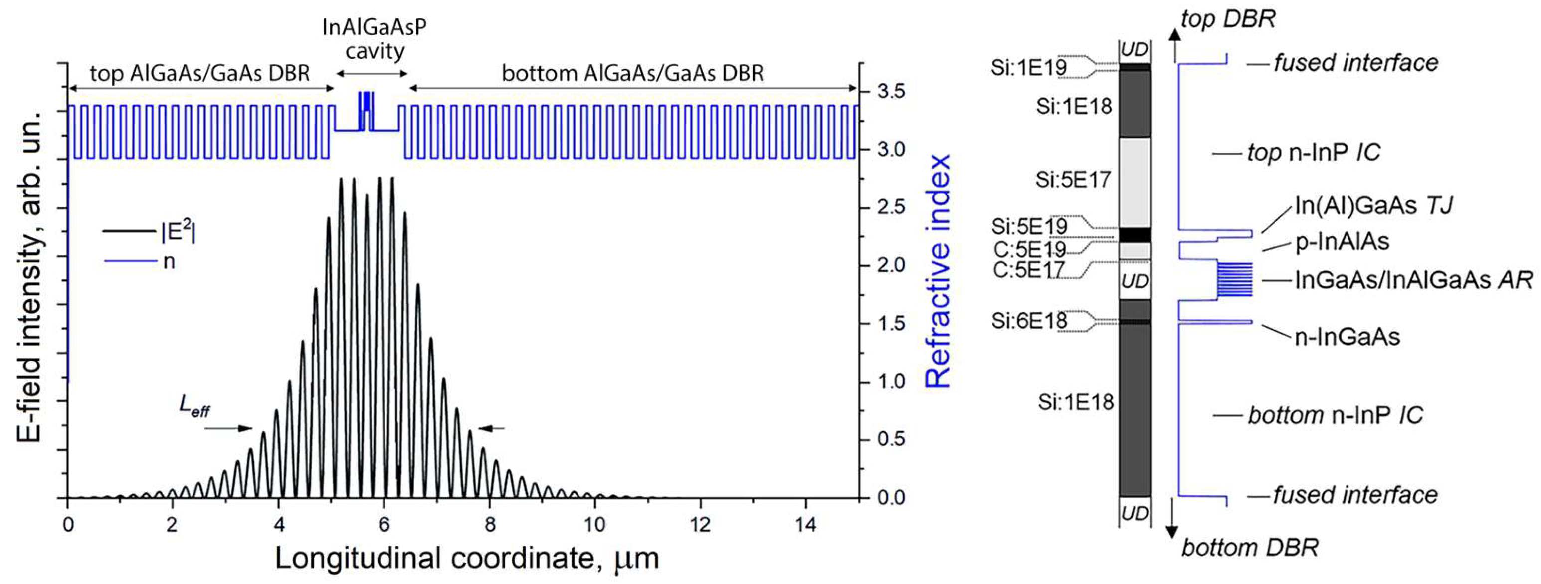
Figure 1. The 1550 nm InGaAs QW-based WF VCSEL: longitudinal distribution of electromagnetic field intensity of the fundamental mode and refractive index (left panel) and zoom of the refractive index and doping profile of the optical cavity (right panel). The schematic cross-section of the microcavity region shows the distributed Bragg reflector, intracavity contact layer, active region, tunnel junction. The n-InGaAs layer close to the QWs is used to obtain an ohmic contact to the lower n-doped IC layer, to reduce free-carrier absorption and to control the etching process to stop at high doping level (selective wet etching). Dependence of the effective refractive index contrast Δneff on the etching depth ΔLTJ of the composite TJ. Figure 1 is adapted, with permission, from Ref. [39]. 2023, IEEE.
Photonics 10 00660 g001
Figure 2. The 1550 nm InGaAs QW-based WF VCSEL: Dependence of the effective refractive index contrast Δneff on the etching depth ΔLTJ of the composite TJ (left panel); an atomic force microscopy image of the overgrown surface and schematic cross-section of the WF VCSEL heterostructure in the microcavity region (right panel).
Photonics 10 00660 g002
Figure 3. The 1550 nm InGaAs QW-based WF VCSEL: (a) STEM/TEM cross-sectional images; (b) schematic cross-section of device. Figure 3b is adapted, with permission, from Ref. [39]. 2023, IEEE.
Photonics 10 00660 g003
Figure 4. CW LIV characteristics of 1550 nm InGaAs QW-based WF VCSELs with 6 μm BTJ diameter measured in CW regime at 20–80 °C: (a) L-type device topology; (b) S-type device topology. The right-hand side shows lasing spectra at 20 °C and at various drive currents. Figure 4b is reprinted, with permission, from Ref. [39]. 2023, IEEE.
Photonics 10 00660 g004
Figure 5. The 1550 nm InGaAs QW-based WF VCSEL with 6 μm BTJ diameter and L-type device topology: (a) measured (points) and fitted (solid lines) S21 versus frequency dependencies for different drive currents; (b) parasitic cutoff frequency as function of drive currents extracted from microwave reflection S11; (c) fR and modulation bandwidth as function of the square root of the drive current above threshold; (d) damping versus fR2 value. The temperature is fixed at 20 °C.
Photonics 10 00660 g005
Figure 6. The 1550 nm InGaAs QW-based WF VCSEL with 6 μm BTJ diameter and S-type device topology: (a) measured (points) and fitted (solid lines) S21 versus frequency dependencies for different drive currents; (b) parasitic cutoff frequency as function of drive currents extracted from microwave reflection S11; (c) fR and modulation bandwidth as a function of the square root of the drive current above threshold; (d) damping versus fR2 value. The temperature was fixed at 20 °C. Figure 6a,c are reprinted, with permission, from Ref. [39]. 2023, IEEE.
Photonics 10 00660 g006
Figure 7. (a) Eye diagram (left) and bit error ratio (right) bathtub curve for a data rate of 25 Gbps for a 1550 nm InGaAs QW-based WF VCSEL with 6 μm BTJ diameter and L-type device topology across a 3 m SMF; (b) the eye diagram (left) and bit error ratio (right) bathtub curve for a data rate of 37 Gbps for a 1550 nm InGaAs QW-based WF VCSEL with 6 μm BTJ diameter and S-type device topology across a 3 m SMF. The temperature of measurements was 20 °C. Figure 7b is reprinted, with permission, from Ref. [39]. 2023, IEEE.
Photonics 10 00660 g007
Disclaimer/Publisher’s Note: The statements, opinions and data contained in all publications are solely those of the individual author(s) and contributor(s) and not of MDPI and/or the editor(s). MDPI and/or the editor(s) disclaim responsibility for any injury to people or property resulting from any ideas, methods, instructions or products referred to in the content.