Abstract
In order to reduce the pumping threshold and achieve a short-cavity single-mode transmission with a narrow-linewidth random fiber laser, we propose a tunable random fiber laser based on the combination of random grating and highly reflective fiber Bragg grating (FBG). Theoretical modeling of a random refractive index-modulated fiber grating was carried out. Random grating is regarded as a linear combination of uniform fiber gratings with different periods. Simulation calculations were performed using the transfer matrix method to determine the preparation parameters. Under the premise of satisfying light localization, a point-by-point method was used to write a random grating in a single-mode fiber using a femtosecond laser according to the simulated parameters. We constructed a random fiber laser with a linewidth of 1.68 kHz and a threshold of 29.2 mW using a random grating and a highly reflective FBG combined with an erbium-doped fiber. Due to the broad scattered wavelength range of the random grating, by changing the central wavelength of the high-reflection FBG, the tunable wavelength of the output laser was realized, and the tunable range was 0.847 nm (1549.110–1549.957 nm). Moreover, the laser’s central wavelength and output power are stable for a long time. Compared with other lasers, the proposed laser has the advantages of a lower threshold, shorter cavity length, narrower linewidth, and a relatively simple structure.
1. Introduction
Since the first realization of the laser output in a random structure by R. V. Ambartsumyan et al. in 1966 [1], the advantage that random lasers can generate laser light by relying only on a disordered medium has led to extensive research and development of random lasers. During this research, various random media have been used to achieve random lasers [2,3,4,5,6,7,8,9,10], including nanoparticle laser dyes, metal nanoparticle polymer films, semiconductor powders, rare earth powders, crystalline powder materials, and even dye-treated human tissues. With the development of the fiber manufacturing process and in-depth research on fiber structure, De Matos, Christiano J. S. et al. [11] built a random fiber laser system for the first time in 2007. The fiber’s unique one-dimensional structure confines the fiber’s light and provides effective one-dimensional random feedback, enabling the laser to achieve higher conversion efficiency. With its simple structure, low coherence, and high cost performance, the random fiber laser has excellent prospects for applications in remote sensing [12], optical imaging [13], medical diagnosis [14], and optical sensing [15].
Random fiber lasers can be broadly classified into three categories based how gain is obtained, which are the stimulated Raman scattering (SRS) effect [16], the stimulated Brillouin scattering (SBS) effect [17,18,19], and the active fiber gain effect [20]. Rayleigh scattering with the disordered refractive index at the center of the fiber provides distributed random feedback to the random fiber laser system. It is, therefore, also known as a random distributed feedback fiber laser (RDFB-FL) [21]. Sergei K. Turitsyn et al. [16] designed mirrorless open cavities to generate laser output by coupling two 1455 nm pump waves of the same power in opposite directions into a conventional fiber of 83 km and using the intrinsic Rayleigh backscattering effect in the fiber to guide the photons to achieve excited Raman amplification. Liang Zhang et al. [22] used a method to enhance the Rayleigh scattering intensity in optical fibers by inscribing random refractive index-modulated points on the fibers and combining them with 25 km single-mode fibers as a Brillouin gain medium to achieve random laser output. However, the cavity length of the laser was still long. Haiyang Wang et al. [23] enhanced the Rayleigh scattering intensity in the fiber by writing a random grating array on the polarization-maintaining fiber to improve the random distribution feedback for the laser system. They used a ring cavity structure to build a laser system. The system uses an NKT laser with a linewidth of 100 Hz as the pump light and a 2 km panda-shaped polarization-maintaining fiber as the Brillouin gain medium, combined with a random grating array to achieve stable laser output. Liang Zhang et al. [24] developed an erbium gain random fiber laser based on a strong random grating, which reduces the cavity length greatly but has a high threshold of about 90 mW. Because random fiber lasers based on Raman gain and Brillouin gain have higher fiber length and pump laser requirements, the structure of random fiber lasers combining active fiber and Rayleigh scattering is simpler.
In order to realize a short-cavity narrow-linewidth random laser output, we propose a short-cavity, narrow-linewidth, tunable random fiber laser based on the combination of random grating and highly reflective FBG. The definition of a random grating is that a large number of refractive index-modulated points are written randomly on the optical fiber in the method of direct inscription. The random spacing points provide a high degree of randomness of the fiber grating. The fabrication parameters of the random grating were obtained by simulation design. The random grating was fabricated by the femtosecond laser point-by-point method, and finally, a narrow-linewidth random fiber laser was constructed with the ultra-narrow reflection peak of the random grating. The laser can generate a stable narrow-linewidth random laser output of 1.68 kHz, the pump threshold is approximately 29.2 mW, and the slope efficiency is approximately 2.3%. Furthermore, the tunability of the output laser wavelength was achieved by changing the central wavelength of the FBG using the water bath temperature.
2. Simulation and Fabrication
The stochastic grating modulates the refractive index of the optical fiber point by point with multiple random periods, so when describing it mathematically, the transfer matrix method, which mainly solves complex grating structures, is used for simulation analysis [25]. The relevant parameters of the random grating applicable to resonance generation in fiber lasers are obtained from the simulation analysis. For a grating with a uniformly varying refractive index, we can represent it as a 2 × 2 matrix, according to which we can find the reflectivity of the grating. For a grating with a nonuniform change in refractive index, we can divide it into multiple segments and consider it as a cascade superposition of multiple uniform gratings. In this way, the whole nonuniform grating can be expressed as a series of two-dimensional matrices in the form of concatenated multiplication. Then, the reflectance can be calculated from this matrix. The random grating is analyzed, as shown in Figure 1. is the length of the fiber between neighbor FBGs, which provides the randomness of the fiber. The random periods of the grating allow for the narrow peaks and broad wavelength range of the reflection spectrum. The narrow reflection peaks act as narrow filters, which select one mode and reduce the mode competition. The random grating is analyzed as a superposition of m-segments of uniform gratings with different random periods, with random intervals between gratings. The refractive index equation for each grating segment can be expressed as , where is the effective refractive index of the grating, is the effective refractive index of the fiber, is the refractive index modulation, and is the refractive index change period of the grating. When the incident beam with a wavelength of has a positive incidence, the mutual coupling coefficient can be expressed as . Then, the amplitudes of the forward and backward propagation modes before and after the ith uniform section are expressed as a matrix of the form [25].
where and are the amplitudes of the forward and backward waves at the cross section, is the length of the uniform cross section, , is the normalized frequency detuning of the grating, indicating the magnitude of the optical frequency deviation from the Bragg frequency, which is independent of the direction of propagation along the grating for all gratings, and . In addition, is the transfer matrix of single-mode fiber [25], and can be expressed by Equation (3):
where , is the distance between two neighbor FBGs. Therefore, the transmission characteristic matrix of the whole grating can be expressed as
where and denote the amplitudes of the forward and backward waves input to the whole grating, and and indicate the amplitudes of the forward and backward waves passing through the entire grating, respectively. According to the transfer matrix , the reflection and transmission coefficients of the grating can be obtained, then the light intensity reflectance and light intensity transmittance can be obtained. In this paper, the periods of gratings and the spacings of refractive index-modulated points are changed randomly, and the rest of the parameters are kept the same.

Figure 1.
Random gratings are represented as a linear combination of periodic gratings of different periods.
We defined the whole length and random spacing of the random grating and used the boundary conditions and to calculate the transmission and reflection spectra of the random grating. In the simulation program, the whole grating length was set to 3.5 cm, the effective refractive index of the fiber was 1.4475, the refractive index modulation depth was [26], and the randomly generated modulation point spacing range was 1–5 m. The calculated reflectance spectra are shown in Figure 2a and the calculated transmission spectra are shown in Figure 2b. Figure 2c shows the reflectance spectrum of the random grating after converting the reflectance units for comparison with the test results after fabrication. Figure 2d shows that the average feedback intensity of the random grating increases with the number of grids.
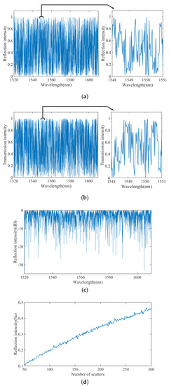
Figure 2.
Simulation results of transfer matrix method. (a) Random grating reflection spectrum; (b) random grating transmission spectrum; (c) random grating reflection spectrum after conversion of units; (d) random grating average reflectance changes with the number of grids.
According to the condition of realizing random laser, the relationship between the random medium length and the localization length is as follows:
where L is the length of random grating, is the light localization length, and is the overall transmissivity of the random grating. After calculation according to Figure 2b, the average transmittance of the whole grating is 0.4189. The localization length is calculated to be 20.11 mm, which is smaller than the grating length and satisfies the photon localization condition. With the increase in pump light, a random laser can be obtained. Therefore, the grating can be prepared according to the parameters obtained from the simulation.
A femtosecond laser was used to achieve random grating fabrication [27], as is shown in Figure 3. Based on the simulation parameters, we used a point-by-point method to inscribe a grating with 11,700 refractive index-modulated points in a 3.5 cm single-mode fiber using a femtosecond laser. The random spacing ranges of the random grating are from 1–5 m, and the software generates the random numbers. The operating parameters of the femtosecond laser are a pulse peak power of 0.2 W, a minimum pulse width of fewer than 290 fs, and a second harmonic wavelength of 515 nm. After the laser passes through an attenuator and a diaphragm, the laser beam is focused into the fiber core by a 63× high-numerical-aperture oil immersion objective, which moves linearly along the Z axis by being fixed to the air-floating platform. The fiber to be fabricated is clamped on a precision air-bearing table with a position accuracy of nm. We used the CCD to observe the fiber in real time. By adjusting the attenuation of the laser energy to 7% and reducing the diameter of the spot, the grating width written by the point-by-point method was less than 1 m, and a random grating was obtained.
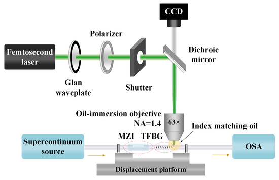
Figure 3.
Diagram of femtosecond laser structure.
After the successful fabrication, the random grating was measured using an optical frequency domain reflectometer (OBR4600, LUNA, Roanoke, VA, USA), and the measurement results are shown in Figure 4. The OBR4600 backlight reflectometer has a spatial resolution of up to 10 m and can test the loss and distribution of the entire optical path of the fiber under test. Figure 4a shows the distance domain measurement of the grating. Figure 4b shows the wavelength domain measurement of the grating. The backscattering signals in the distance domain clearly show that the random grating is roughly written at 1.640–1.675 m of the fiber. The backscattering signals in the wavelength domain clearly show that the reflection spectrum in the random grating shows a large number of peaks with narrow linewidths. After several fabrication experiments, the optimal laser power parameters for preparing the random grating were obtained. The laser power and position focused on the core during the preparation process affect the refractive index modulation depth, so the intensity of the actual prepared random grating reflection spectra is lower than the simulated results compared with the simulated random grating reflection spectra. Multiple interference peaks are formed between the random grating’s different refractive index-modulated points in the measured random grating reflection spectrum. The narrow peaks act as narrow filters, suppressing random modes and achieving single-mode operation with narrow linewidth.
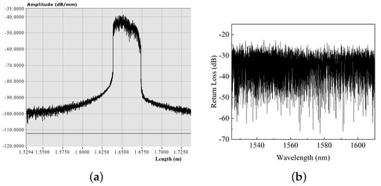
Figure 4.
The backscattering signals of the random grating. (a) The backscattering signals in distance domain; (b) the backscattering signals in wavelength domain.
3. Laser Structure and Principle
Random lasers based on random gratings mostly use linear cavity structures. In the linear cavity structure, the beams transmitted in opposite directions are prone to form standing waves, which not only form a spatial hole-burning effect in the gain medium but also may form a mode competition. In addition, the conventional random laser based on random grating inscribes the grating on the erbium-doped fiber, resulting in a laser susceptible to temperature effects and unstable laser output. The proposed laser uses a ring resonator, and the resonant cavity structure is inscribed in a single-mode fiber, which alleviates the temperature effect in the cavity on the laser system. The erbium-doped fiber random laser structure is shown in Figure 5a. The pump laser is a 974 nm semiconductor laser (Pump LD, MCSPL-980-300-H1-1-FA-T1, MC Fiber Optics, Shenzhen, China); the pump light is injected into a 0.5 m long section of erbium-doped fiber (EDF, Er110-4/125, nLIGHT, Vancouver, WA, USA) with a peak core absorption of 110 dB/m at 1530 nm through a 1550 nm/974 nm wavelength division multiplexer (WDM, MCWDM-9855-P-00-10-L-FA, MC Fiber Optics, Shenzhen, China), and the pump light entering the gain medium achieves particle number inversion to produce excited radiation. The amplified light passes through the fiber circulator into the random grating and is propagated through the cavity by the scattering provided by it. The isolator allows only one-way light transmission in the annular cavity; when the light propagates to the output coupler, 90% of the light is sent back to the annular cavity, and 10% is used as the laser output. Combined with the device pigtail length, the overall cavity length of the laser is approximately 8.18 m. The selected highly doped active fiber effectively improves the gain effect on the pump light source and reduces the length of the ring cavity. Due to the broad gain bandwidth of EDF and the broad scattered wavelength range of random grating, we can achieve a wide tunable range.
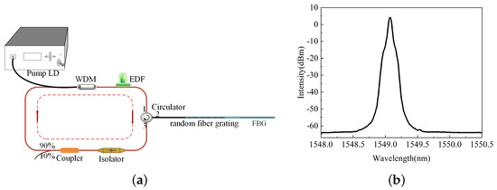
Figure 5.
Random fiber laser. (a) Diagram of structure; (b) optical spectrum of laser output.
The output of the erbium-doped fiber laser based on the random grating is detected and analyzed by a optical spectrum analyzer with a resolution of 0.05 nm (AQ6374, YOKOGAWA, Tokyo, Japan). Figure 5b shows the output spectrum of the laser, which is pure. The laser runs in a single wavelength state with a central wavelength of 1549.11 nm and an optical signal to noise ratio of 68 dB. The peak of the spectrum is narrow, with a 3 dB bandwidth of about 0.05 nm. Since the wavelength limit resolution of the spectrometer is 0.05 nm, the measured bandwidth of the spectrum cannot represent the true bandwidth of the laser, and further measurements are required. When the laser works, multiple interferences are formed in the random grating. The interference spectra overlap to produce sharp reflection peaks, which provide random feedback for the laser in the cavity. The photon localization effect of strongly reflective random grating and the high reflectivity of FBG provide conditions for the stable single-wavelength output of lasers.
4. Output Characteristics of Lasers
The laser output characteristics of this random fiber laser vary with the pump laser power, as shown in Figure 6. Figure 6a shows the measured laser spectrum as the pump laser increases when the central wavelength of the frequency-selective FBG is fixed at 1549.11 nm. It can be seen from the figure that when the threshold power is below 29.2 mW, the erbium-doped fiber laser generates a weak broadband spontaneous emission (ASE) spectrum. When the power of the pump light source reaches 29.2 mW, the laser is generated, and only one laser peak appears on the spectrometer. The relationship between the laser output power and the pump power is measured by an optical power meter (S144C, Thorlabs, Newtown, CT, USA). The output of the laser is directly connected to the optical power meter, and the power change of the optical power meter is observed while adjusting the power of the pump source to obtain the relationship graph shown in Figure 6b. The graph shows that the output power tends to increase linearly with a slope efficiency of about 2.3% when the pump power exceeds the threshold value.
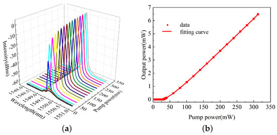
Figure 6.
(a) The change in laser output spectrum with the pumped laser; (b) the change in laser output power with the pumped laser.
To further investigate the output characteristics of this random laser, we conducted experiments at 17 °C in a laboratory environment. We turned on the pump source and set the pump power to 300 mW. In the first 6 min, the wavelength and output power of the spectral peak were measured every minute, and then the laser output spectrum was measured every 10 min, for a total of 12 measurements. We obtained 12 sets of data. The measurement results are shown in Figure 7, and it can be concluded that the wavelength and output power fluctuations are 0.05 nm and 0.94 dB, respectively. The filtering effect of the narrow broadband of the fiber Bragg grating can be seen, making the central wavelength of the output laser more stable. On the other hand, the mode competition in the laser cavity is relatively strong at this pump power. The power fluctuations are more obvious in the first 5 min and 5–10 min, and the fluctuations tend to slow down after 10 min. The experimental results show that the stability of the output laser can be guaranteed for a short time after startup.
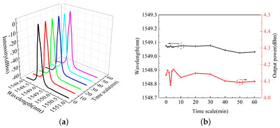
Figure 7.
(a) Random laser output spectrum obtained from multiple measurements; (b) random laser wavelength and output power change with time.
We chose the delayed self-heterodyne method to test the output linewidth of the laser, and the test structure is shown in Figure 8a. The random laser enters the test system and is first divided into two paths by a 50/50 coupler, one into a delayed standard single-mode fiber with a length of 22.2 km, and the other into an acousto-optic modulator (AOM; SFO5519-T-M080-0.4C2J-3-F2S-01, Gooch and Housego, Ilminster Somerset, Britain), which is frequency-shifted by 80 MHz. The two signals enter the coupler and are received by the photodetector (PD; PDB450C-AC, Thorlabs, Newtown, CT, USA). Finally, the spectrum analyzer (ESA; 4051-E-S, Ceyear, Qingdao, China) analyzes the beat frequency signal, and the detected beat frequency signal is shown in Figure 8b. From the figure, we can know that the beat frequency signal shows a good Lorentzian line pattern, and the spectral line width is about 1.68 kHz according to the Lorentzian approximation. The output linewidth is also tested when the resonant cavity structure of the laser is just an ordinary FBG. We obtain the beat frequency signal, as shown in Figure 8c, and the spectral linewidth is about 2.79 kHz. When the resonant cavity is a random grating combined with a highly reflective Bragg grating, the Lorentz line pattern is better, and has the effect of compressing the linewidth, which results in a narrow-linewidth random fiber laser.
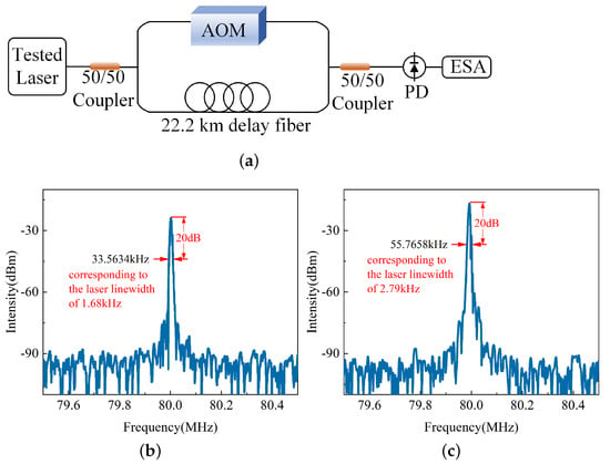
Figure 8.
Laser linewidth test. (a) Diagram of the delayed self-heterodyne method; (b) resonant cavity for random with FBG, beat frequency signal spectrum; (c) resonant cavity for FBG, beat frequency signal spectrum.
Using the frequency-selective filtering characteristics of the highly reflective FBG, the wavelength tunability of the output laser can be achieved by changing the center wavelength of the FBG. The random grating and Bragg grating were placed in a water bath without any stress, and the pump power was maintained at 300 mW. After we added water to cover the random grating and Bragg grating in a laboratory environment at a temperature of 17 °C, we heated the water to boiling, and then stopped heating. The water temperature at boiling was 95 °C, and when the water temperature decreased to 90 °C, the laser spectrum at that temperature was recorded. Thereafter, the output spectrum of the laser was recorded once for every 10 °C decrease in the water temperature. The temperature ranged from 20 °C to 95 °C for a total of nine random laser output spectra recorded. The measurement results are shown in Figure 9, and it can be concluded that the wavelength drift is 0.847 nm (1549.110–1549.957 nm).
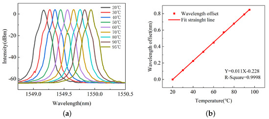
Figure 9.
(a) The relation between the output spectrum of random laser and the temperature; (b) the wavelength changes during the cooling processes.
5. Conclusions
The proposed laser uses a random grating written point-by-point by a femtosecond laser as a random feedback medium, uses erbium-doped fiber for gain amplification, combines isolators and couplers to form a ring cavity structure, and uses a highly reflective Bragg grating to select the laser output at a wavelength of 1549.11 nm. Experimental results show that the linewidth is 1.68 kHz, the threshold of the laser is 29.2 mW, and the slope efficiency is 2.3%. The tunable output laser wavelength is achieved with the FBG tuning device with a tuning range of 0.847 nm (1549.110–1549.957 nm). Compared with the existing random fiber lasers, the proposed laser has the advantages of a relatively shorter laser cavity length, narrower linewidth, and simpler structure. During the experiment, the parameters in the laser structure were not strictly controlled to obtain the optimal threshold and slope. The next step is to optimize the cavity length of the resonator structure, reduce the loss, improve the slope efficiency, and realize the tunable design of tens of nm. On the premise of ensuring the stability of the laser, the parameters affecting the composing of gratings are further studied.
Author Contributions
Conceptualization, Y.N.; methodology, P.J.; software, Y.N.; validation, Y.N., J.S. and J.W.; writing—original draft preparation, Y.N.; writing—review and editing, Q.R. and G.A.; supervision, J.X.; project administration, J.X. All authors have read and agreed to the published version of the manuscript.
Funding
This research was supported by the National Natural Science Foundation of China under Grant 51935011 and 52075505; the Innovative Research Group Project of National Science Foundation of China under Grant 51821003; the special fund for Science and Technology Innovation Teams of Shanxi Province under Grant 202204051001016; Key research and development program of Shanxi Province under Grant 202102150101006.
Institutional Review Board Statement
Not applicable.
Informed Consent Statement
Not applicable.
Data Availability Statement
Data will be made available on request.
Conflicts of Interest
The authors declare no conflict of interest.
References
- Ambartsumyan, R.; Basov, N.; Kryukov, P.; Letokhov, V. A laser with a nonresonant feedback. IEEE J. Quantum Electron 1966, 2, 442–446. [Google Scholar] [CrossRef]
- Gottardo, S.; Cavalieri, S.; Yaroshchuk, O.; Wiersma, D.S. Quasi-two-dimensional diffusive random laser action. Phys. Rev. Lett. 2004, 93, 263901. [Google Scholar] [CrossRef] [PubMed]
- Zhu, J.L.; Li, W.H.; Sun, Y.; Lu, J.G.; Song, X.L.; Chen, C.Y.; Zhang, Z.; Su, Y. Random laser emission in a sphere-phase liquid crystal. Appl. Phys. Lett. 2015, 106, 191903. [Google Scholar] [CrossRef]
- Lawandy, N.M.; Balachandran, R.; Gomes, A.; Sauvain, E. Laser action in strongly scattering media. Nature 1994, 368, 436–438. [Google Scholar] [CrossRef]
- Williams, G.; Bayram, S.; Rand, S.; Hinklin, T.; Laine, R. Laser action in strongly scattering rare-earth-metal-doped dielectric nanophosphors. Phys. Rev. A 2001, 65, 013807. [Google Scholar] [CrossRef]
- Cao, H.; Zhao, Y.; Ho, S.; Seelig, E.; Wang, Q.; Chang, R. Random laser action in semiconductor powder. Phys. Rev. Lett. 1999, 82, 2278. [Google Scholar] [CrossRef]
- Sakai, M.; Inose, Y.; Ema, K.; Ohtsuki, T.; Sekiguchi, H.; Kikuchi, A.; Kishino, K. Random laser action in GaN nanocolumns. Appl. Phys. Lett. 2010, 97, 151109. [Google Scholar] [CrossRef]
- Yu, S.F.; Yuen, C.; Lau, S.P.; Park, W.; Yi, G.C. Random laser action in ZnO nanorod arrays embedded in ZnO epilayers. Appl. Phys. Lett. 2004, 84, 3241–3243. [Google Scholar] [CrossRef]
- Meng, X.; Fujita, K.; Zong, Y.; Murai, S.; Tanaka, K. Random lasers with coherent feedback from highly transparent polymer films embedded with silver nanoparticles. Appl. Phys. Lett. 2008, 92, 201112. [Google Scholar] [CrossRef]
- Polson, R.C.; Vardeny, Z.V. Random lasing in human tissues. Appl. Phys. Lett. 2004, 85, 1289–1291. [Google Scholar] [CrossRef]
- de Matos, C.J.; Menezes, L.d.S.; Brito-Silva, A.M.; Gámez, M.M.; Gomes, A.S.; de Araújo, C.B. Random fiber laser. Phys. Rev. Lett. 2007, 99, 153903. [Google Scholar] [CrossRef] [PubMed]
- Wiersma, D.S.; Cavalieri, S. A temperature-tunable random laser. Nature 2001, 414, 708–709. [Google Scholar] [CrossRef] [PubMed]
- Redding, B.; Choma, M.A.; Cao, H. Speckle-free laser imaging using random laser illumination. Nat. Photonics 2012, 6, 355–359. [Google Scholar] [CrossRef]
- Rao, Y. Research advances of random fiber lasers and its applications. Acta Photonica Sin. 2019, 48, 1148002. [Google Scholar]
- Xu, Y.; Zhang, L.; Gao, S.; Lu, P.; Mihailov, S.; Bao, X. Highly sensitive fiber random-grating-based random laser sensor for ultrasound detection. Opt. Lett. 2017, 42, 1353–1356. [Google Scholar] [CrossRef]
- Turitsyn, S.K.; Babin, S.A.; El-Taher, A.E.; Harper, P.; Churkin, D.V.; Kablukov, S.I.; Ania-Castañón, J.D.; Karalekas, V.; Podivilov, E.V. Random distributed feedback fibre laser. Nat. Photonics 2010, 4, 231–235. [Google Scholar] [CrossRef]
- Fotiadi, A.A.; Kiyan, R.V. Cooperative stimulated Brillouin and Rayleigh backscattering process in optical fiber. Opt. Lett. 1998, 23, 1805–1807. [Google Scholar] [CrossRef]
- Wang, H.; Zhou, Z.; Chen, L.; Bao, X. Acoustic wave coupling in dual-wavelength orthogonal polarized brillouin random fiber laser using polarization-maintaining fiber. J. Light. Technol. 2022, 40, 2541–2547. [Google Scholar] [CrossRef]
- Wang, H.; Chen, C.; Lu, P.; Mihailov, S.; Chen, L.; Bao, X. Reducing frequency fluctuation in a Brillouin random fiber laser by a random fiber grating ring resonator. Opt. Lett. 2022, 47, 3900–3903. [Google Scholar] [CrossRef]
- Lizárraga, N.; Puente, N.; Chaikina, E.; Leskova, T.; Méndez, E. Single-mode Er-doped fiber random laser with distributed Bragg grating feedback. Opt. Express 2009, 17, 395–404. [Google Scholar] [CrossRef]
- Turitsyn, S.K.; Babin, S.A.; Churkin, D.V.; Vatnik, I.D.; Nikulin, M.; Podivilov, E.V. Random distributed feedback fibre lasers. Phys. Rep. 2014, 542, 133–193. [Google Scholar] [CrossRef]
- Zhang, L.; Xu, Y.; Lu, P.; Mihailov, S.; Chen, L.; Bao, X. Multi-wavelength Brillouin random fiber laser via distributed feedback from a random fiber grating. J. Light. Technol. 2018, 36, 2122–2128. [Google Scholar] [CrossRef]
- Wang, H.; Lu, P.; Chen, C.; Mihailov, S.; Chen, L.; Bao, X. Stabilizing Brillouin random laser with photon localization by feedback of distributed random fiber grating array. Opt. Express 2022, 30, 20712–20724. [Google Scholar] [CrossRef] [PubMed]
- Zhang, L.; Lu, P.; Zhou, Z.; Wang, Y.; Mihailov, S.; Chen, L.; Bao, X. High-efficiency random fiber laser based on strong random fiber grating for MHz ultrasonic sensing. IEEE Sens. J. 2020, 20, 5885–5892. [Google Scholar] [CrossRef]
- Erdogan, T. Fiber grating spectra. J. Light. Technol. 1997, 15, 1277–1294. [Google Scholar] [CrossRef]
- Qin, H.; He, Q.; Xing, Z.; Guo, X.; Yan, Z.; Sun, Q.; Zhou, K.; Wang, H.; Liu, D.; Zhang, L. Numerical and experimental characterization of radiation mode of 45° tilted fiber grating. J. Light. Technol. 2019, 37, 3777–3783. [Google Scholar] [CrossRef]
- Lu, P.; Mihailov, S.J.; Coulas, D.; Ding, H.; Bao, X. Low-loss random fiber gratings made with an fs-IR laser for distributed fiber sensing. J. Light. Technol. 2019, 37, 4697–4702. [Google Scholar] [CrossRef]
Disclaimer/Publisher’s Note: The statements, opinions and data contained in all publications are solely those of the individual author(s) and contributor(s) and not of MDPI and/or the editor(s). MDPI and/or the editor(s) disclaim responsibility for any injury to people or property resulting from any ideas, methods, instructions or products referred to in the content. |
© 2023 by the authors. Licensee MDPI, Basel, Switzerland. This article is an open access article distributed under the terms and conditions of the Creative Commons Attribution (CC BY) license (https://creativecommons.org/licenses/by/4.0/).