Abstract
Source mask optimization (SMO) is an effective method for improving the image quality of high-node lithography. Reasonable algorithm optimization is the critical issue in SMO. A GA-APSO hybrid algorithm, combining genetic algorithm (GA) and adaptive particle swarm optimization (APSO), was proposed to inversely obtain the global optimal distribution of the pixelated source and mask in the lithographic imaging process. The computational efficiency was improved by combining the GA and PSO algorithms. Additionally, the global search and local search were balanced through adaptive strategies, leading to a closer result to the global optimal solution. To verify the performance of GA-APSO, simple symmetric patterns and complex patterns were optimized and compared with GA and APSO, respectively. The results show that the pattern errors (PEs) of the resist image optimized by GA-APSO were reduced by 40.13–52.94% and 10.28–33.31% compared to GA and APSO, respectively. The time cost of GA-APSO was reduced by 75.91–87.00% and 48.43–58.66% compared to GA and APSO, respectively. Moreover, repeated calculation showed that the GA-APSO results were relatively stable. The results demonstrate the superior performance of GA-APSO in efficiency, accuracy, and repeatability for source and mask optimization.
1. Introduction
Lithography is the primary method of manufacturing micromachining. Higher lithography resolution is required according to Moore’s Law. Based on the Rayleigh Criterion, shortening wavelength, increasing numerical aperture (NA), and enhancing technology factor are three methods of improving lithography resolution. However, some unfavorable factors, such as diffraction effect and heat accumulation, can cause image quality reduction during lithography. High-frequency information, such as corners or sharp lines in the mask, cannot be effectively transmitted to wafer. These negative factors become more significant as lithography resolution improves.
Resolution-enhancement technology (RET) [1] is introduced to enhance image quality, eliminate these negative factors, and enhance technology factors. Traditional RET includes off-axis illumination (OAI), phase-shifting mask (PSM), and optical proximity correction (OPC). These examples of traditional RET have a low degree of freedom due to optimizing mask or light source modules individually. Source mask optimization (SMO) is proposed, which increases the optimal degree of freedom by optimizing the source and mask at the same time [2].
The input of SMO includes the parameters of the lithography process, such as numerical aperture (NA) and photoresist [3]. Based on the input data, SMO generates an initial light source and mask. Then, the light source and mask are optimized by an intelligent algorithm on an imaging model until the criterion functions are satisfied. Both imaging quality and machinability can be involved in the criterion functions [4].
An important issue for SMO is to present a high-efficiency, reasonable optimization algorithm to obtain the global optimal solution.
Traditional gradient-based methods of solving optimization problems, such as conjugate gradient (CG) [5,6], steepest descent (SD) [7], and gradient descent (GD) [8,9,10], have been used to solve the SMO problem. These methods are relatively efficient. However, they tend to fall into local optimums for large-scale optimization variables and nonlinear characteristics in SMO.
Recently, metaheuristic algorithms have been widely used in optimization problems in extensive fields for their excellent adaptability to different optimization problems. Metaheuristic algorithms can be classified as population-based algorithms and neighborhood-based algorithms. Genetic algorithms (GAs) and particle swarm optimization algorithm (PSO) are typical population-based algorithms, and have been used to optimize source and mask universally.
GAs obtain the optimal solution by mimicking natural selection [11]. Tim Fühner et al. [12,13,14,15] used a GA for SMO, and discussed the convergence behavior and different weight settings of criteria function. This method does not require any additional a priori knowledge about lithographic processes. Yang Chaoxing et al. [16] studied the method of improving the iterative speed of a genetic algorithm. By changing the fitness function and using a multichromosome genetic algorithm, the number of evolutions is reduced and the iterations speed up.
PSO is the mathematical model of a bird’s behavior when searching for food, escaping from predators, and searching. PSO has been employed in several varieties of problems, from classical mathematical programming problems to scientific optimization problems [17]. Wang Lei et al. [18] compared PSO and GAs using a complex mask pattern with a cross-gate design. The results revealed that PSO can improve the quality of lithography imaging. Zhang Zhinan [19] et al. increased the optimization rate of EUV SMO using SL-PSO (social learning PSO), in which the particles are updated based on historical information. Sun Haifeng [20] et al. combined PSO with the adaptive nonlinear control strategy (ANCS) to break away from the local optimum.
In summary, the single metaheuristic algorithm has its own limitations in the optimization process. GAs balance the depth and breadth of optimal solution search, but also have a strong parameter dependence. PSO has strong adaptability, but can easily fall into the local optimum. This paper proposes a GA-APSO algorithm to inversely obtain the global optimal distribution of the pixelated source and mask in the lithographic imaging process. The computational efficiency is improved by combining the GA and PSO algorithms. Additionally, the global search and local search are balanced through adaptive strategies, leading to a closer result to the global optimal solution.
2. Methodology
2.1. Partially Coherent Imaging Model
In this section, the lithography imaging process of the partially coherent imaging model is explained. Partially coherent illumination is widely used in lithography to improve resolution. A typical immersion lithography system is shown in Figure 1. The ray emitted by the illumination source forms the Kohler illumination through a condenser lens. Then, the ray passes through the mask and produces a diffracted ray carrying pattern information. Finally, the ray through the objective lenses images the feature on the mask onto the resist. Spatial intensity distribution on the resist is formed by superimposing the images of the source at different positions. The images are obtained by moving pupil position. Then, the partial coherence imaging model can be expressed by [21]:
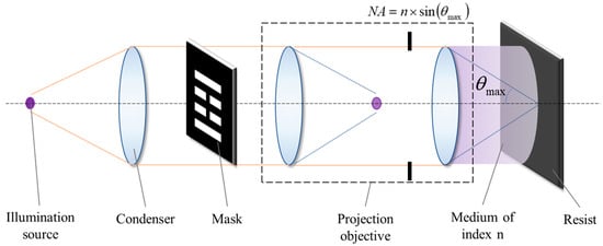
Figure 1.
Immersion lithography system.
In Equation (1), represents the intensity distribution of aerial images in optical lithography. and are the frequency-domain coordinates of the pupil and mask, respectively. is an extended illumination source. is the mask frequency spectrum. represent the pupil function characterizing light propagation from a point on the object plane to an image point. To simulate the imaging model, Equation (1) can be approximately expressed as:
in which represents the efficient pixels of the source, is an inverse Fourier transform operation, and indicates that the pupil is shifted with the position change of the source point . In the simulation, the photoresist effect was approximated using a sigmoid function. The resist image of the aerial image on the wafer surface can be displayed after development [22].
where is the layout distribution of the resist image, represents a threshold function, is the threshold of the sigmoid function, and controls the steepness of intensity transition.
2.2. Source and Mask Optimization Using GA-APSO Algorithm
Figure 2 represents the coding regulations of the source and mask. To reduce computational complexity, half of the symmetrical parts are encoded. In calculation, the complete source and mask are restored symmetrically. For the four-fold symmetrical source and mask shown in the figure, only the first-quadrant variables are encoded.
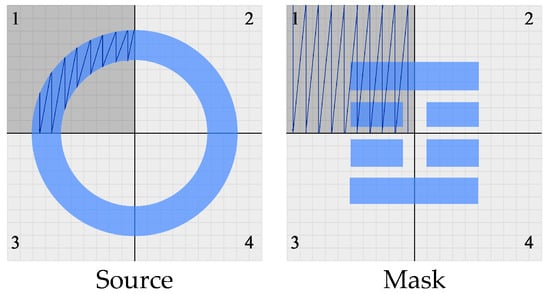
Figure 2.
Coding of source and mask. The source and the pattern are divided into four regions according to the symmetry, represented as 1,2,3,4.
SMO is a multiparameter with single objective optimization. For a certain system, the imaging result can be calculated using the partially coherent imaging model. The distance between the real imaging result and the ideal image can be evaluated by pattern errors (Pes), which are the L1 norm of the subtraction between and . The object of SMO is to minimize the Pes. Every pixel of source and mask is limited between 0 and 1 in simulation. Pes are defined as [20]:
where is the intensity distribution of the ideal image and is the intensity distribution of the real image.
The source and mask are optimized by the GA-APSO algorithm. APSO is a bionic algorithm simulating the bird foraging process. In APSO, each particle updates its swarming speed based on memory and current global optimal position. GA is a method to search for the optimal solution by simulating the natural evolution process. In Gas, populations iterate through genetics and mutation. APSO has ascendency in convergence, but can easily fall into local optimum. However, GA is advanced in global optimization, while it has poor convergence. The optimization method in this paper combined GA and APSO to enhance optimization efficiency and retain global optimal search capability.
The steps of the GA-APSO algorithm are as follows:
- (1)
- Initialization of the population
The parameters are initialized. Additionally, an initial population is randomly generated in the feasible region and the initial fitness is calculated.
- (2)
- Population update by APSO
According to the fitness, the population is updated by APSO. Velocity of each individual is as follows:
where: is the constriction coefficient; is the inertia weight factor; is the velocity of j-th individual in i-th iteration; and are the individual learning factor and social learning factor, respectively; and are random numbers which range from zero to one; and and are the personal best for the j-th individual, and the global best in the population, respectively. Velocity is limited in a certain range.
Individual learning factor and social learning factor reflect the acceleration of individual learning and social learning, respectively. There are different requirements for and at different stages of the iteration. Hence, adaptive strategies of and are introduced during iterations. During the early iteration, the individual cognitive acceleration is increased to enlarge the search zone of individual particles scattered in the whole search space. During the later period of iteration, is decreased and is increased properly to make individual particles jump out of the local optimum and improve convergence performance. The adaptive variation rule is as follows:
where and are the parameters for the i-th step.
Additionally, the constriction coefficient [17] is introduced to speed up the convergence, and the constriction coefficient is computed as:
where .
To balance global optimization ability in the early iteration and strong local optimization ability in the late iteration, inertia weight factor requires a relatively large value in initial iteration and decreases in late iteration. Inertia weight factor is controlled by a hyperbolic tangent function which is shown in Figure 3:
where: and are the maximum and minima inertia weight factor; and is the maximum iteration number.
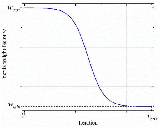
Figure 3.
Inertia weight factor with iteration changing.
- (3)
- Crossover operator
First, the individual crosses are determined according to crossover probability . Two individuals are randomly selected as parents from the mating pool. Then, cross-chromosome position is selected randomly. Genes in two parent positions are exchanged, as shown in Figure 4.
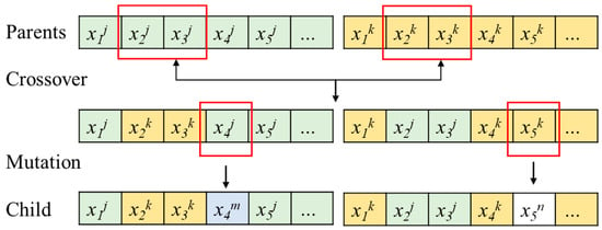
Figure 4.
Crossover and mutation operator. Genes in the red box are selected for crossover or mutation.
- (4)
- Mutation operator
First, whether the individual mutates is determined according to mutation probability . Mutation chromosome position is selected randomly. The selected genes change randomly in the feasible region.
Then, the child population is generated. Additionally, the fitness of the child population is calculated and the personal best for each individual and the global best in the population are updated.
Steps (2)~(4) are repeated until the maximum iteration number occurs or fitness changes between the set number of iterations are less than the tolerance .
The flow chart of source and mask optimization is as shown in Figure 5. Source and mask optimization steps are as follows:
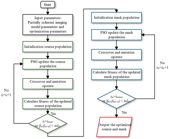
Figure 5.
SMO flow chart.
- (1)
- Initialization
Input all the parameters of the partially coherent imaging model, including wave length , lighting model, mask size, and sampling points of light source and mask. Additionally, input all the parameters which the optimization algorithm needs, including maximum iteration numbers and , convergence tolerance and , population size, maximum and minima inertia weight factor maximum and , maximum and minimal crossover probability and , and maximum and minimal mutation probability and .
- (2)
- Source optimization
Initialize the source population randomly selected in the feasible region. Then, optimize the source using the GA-APSO algorithm. The imaging results with source population are calculated according to the partially coherent imaging model, and fitness is evaluated by pattern errors (Pes). Update the source population until the iteration number is greater than the maximum iteration number or the fitness change between the set number of iterations is less than the tolerance .
- (3)
- Mask optimization
Initialize the mask population randomly selected in the feasible region. Then, optimize the mask using the GA-APSO algorithm. The imaging results with source population are calculated according to the partially coherent imaging model and fitness is evaluated by pattern errors (Pes). Update mask population until the iteration number is greater than the maximum iteration number or the fitness change between the set number of iterations is less than the tolerance . Then, the optimization of the mask and source is finished and outputs the best mask and source.
3. Simulations and Discussion
3.1. Simulation Parameters
In this paper, the 193 nm immersion lithography model with a 45 nm node was conducted. NA is 1.35. Source optimization was initialized by annular illumination, as shown in Figure 6. The partial coherence factors and were, respectively, set to 0.65 and 0.95. The source was pixeled to a matrix. Mask 1 was sampled as a matrix. Mask 2 and Mask 3 were sampled as a matrix. Three masks with different pattern complexities, as shown in Figure 7, were simulated in this study. Mask 1 was asymmetric and only encoded the first quadrant of the pattern. Mask 2 and Mask 3 were complex asymmetric patterns and encoded the whole patterns. The photoresist parameters and were 0.28 and 85, respectively.
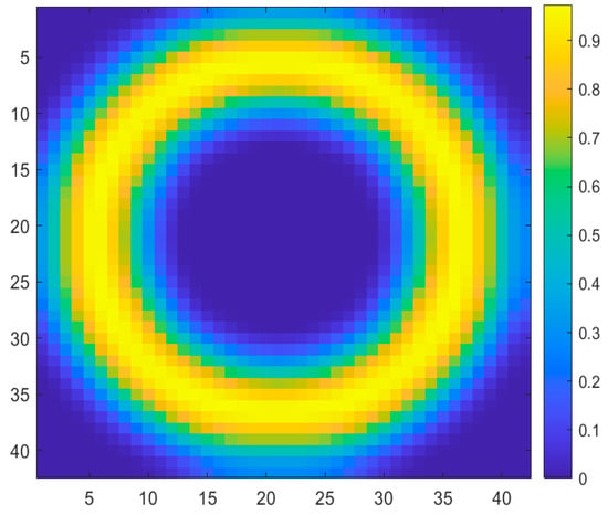
Figure 6.
Initial illumination source.
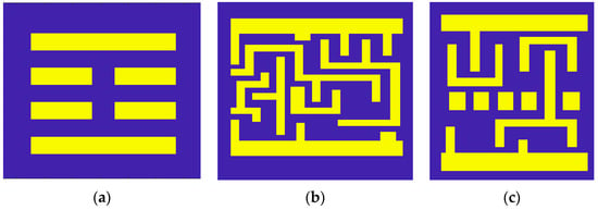
Figure 7.
Three typical target patterns. (a) Pattern 1, (b) Pattern 2, (c) Pattern 3.
Source and mask optimization (SMO) using the GA-APSO algorithm was compared with APSO and GA. In the simulation, the parameters of the algorithm were set as shown in Table 1. The iteration steps were set as 500 for source optimization and 1000 for mask optimization. Additionally, the population size was set as 50 in this simulation.

Table 1.
Algorithm parameters.
3.2. Simulation Results
Initial and optimized resist images are represented in Figure 8. The lines of the initial resist image overlap with each other. After SMO, the quality of resist image improved significantly. For the three masks, the Pes of resist image optimized by GA-APSO improved by 77.18%, 69.82%, and 75.80%, respectively. Among the three algorithms, the Pes of GA-APSO was the lowest. Compared to GA and APSO, the Pes of resist image by GA-APSO reduced by 40.13–52.94% and 10.28–33.31%, respectively. Especially in the optimization of complex patterns (Mask 2 and Mask 3), the GA-APSO performs better. There are some missing lines and partial adhesions in the resist images of Mask 2 and Mask 3 optimized by GA and APSO. This situation has been well-improved by GA-APSO.
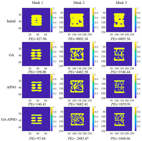
Figure 8.
Resist image after SMO by GA, APSO, and GA-APSO.
Source and mask optimization performance of the GA-APSO algorithm was compared with APSO and GA. Sources after optimization are shown in Figure 9. Masks after optimization are shown in Figure 10. After SMO, the source for Mask 1, which consists of only one direction line, was approximate to dipole illumination. Additionally, for Mask 2 and Mask 3 with irregular patterns, sources after SMO were approximate to quadra illumination. The distribution of horizontal and vertical lines affects the final illumination form. The optimized source for patterns with unidirectional lines such as Mask 1 tend to dipole illumination. The angle of dipole illumination is associated with the direction of the lines. The optimized source for patterns with both horizontal and vertical lines such as Mask 2 and Mask 3 tend quadra illumination. Moreover, affected by the different distribution of horizontal and vertical lines, one direction of the quadra illumination is stronger.
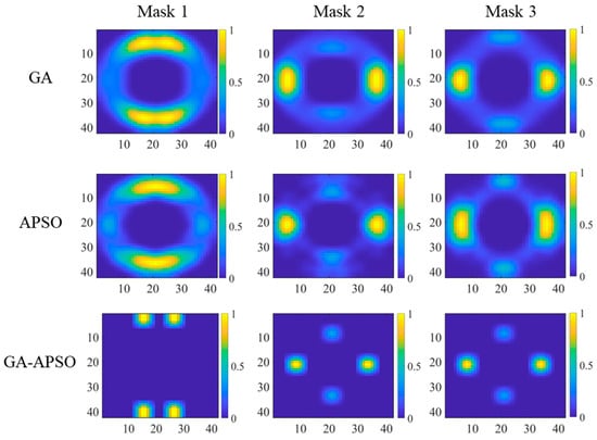
Figure 9.
Sources after SMO by GA, APSO, and GA-APSO.
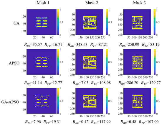
Figure 10.
Masks after SMO by GA, APSO and GA-APSO.
Masks after optimization are presented in Figure 10. The binary error and total variation were introduced to evaluate the manufacturability of the mask and the complexity of the mask pattern, which are defined as follows [23]:
in which is the mask matrix, is the L1 norm operator, and the lower value of binary error and total variation represent the better manufacturability.
Masks after optimization by the presented GA-APSO algorithm have obvious advantages in . by GA-APSO decreased by 77.6–99.9% and 28.5–99.8% compared with GA and APSO, respectively. The of masks obtained using GA were the largest among the three. The total variation of masks by three algorithms had slight difference.
Figure 11 represents the convergence curve of GA, APSO, and GA-APSO. The SO step converged faster than the MO step because of the smaller number of variables. Pes dropped rapidly at the beginning of the iteration. Then, GA and APSO tended to converge to a local optimum fast. GA-APSO achieved better Pes compared to GA and APSO in both the source optimization (SO) step and mask optimization (MO) step. To obtain an equivalent Pes with GA and APSO, GA-APSO costs less iteration. Additionally, the results of GA-APSO are closer to the global optimal solution.

Figure 11.
Convergence curves in the iterative process. (a–c) represent the convergence curves of masks with different patterns: (a) Pattern 1; (b) Pattern 2; (c) Pattern 3.
The time cost of the three algorithms was evaluated under the same calculation conditions (in Figure 12). GA-APSO has obvious advantages in algorithm efficiency. Time cost of GA-APSO reduced by 75.91%, 58.66% for Mask 1, by 87.00%, 50.96% for Mask 2, and by 82.91%, 48.43% for Mask 3. The GA algorithm costed the most time. Especially in complex mask optimization, the time cost for the GA algorithm improved sharply. GA-APSO and PSO costed a slightly higher time for complex mask than for simple mask.
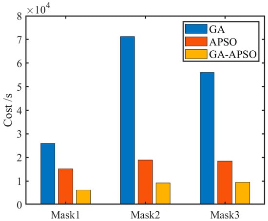
Figure 12.
Efficiencies of three algorithms.
As the initial population is randomly generated near the initial source and mask, this may affect the accuracy and convergence efficiency of the final results. The three masks were optimized three times using the GA-APSO to assess differences in convergence process and results. Figure 13 shows the convergence curve for the three times. For Mask 1, Pes has a certain difference within 200 iteration steps in the SO step, but finally converges to an almost consistent result. For Mask 2, the three iterations differ significantly. For Mask 3, the three iterations show a slight difference. Resist images of the three calculations are presented in Figure 14.

Figure 13.
Convergence curves in the iterative processes of three calculations by GA-APSO. (a–c) represent the convergence curves of masks with different patterns: (a) Pattern 1; (b) Pattern 2; (c) Pattern 3.
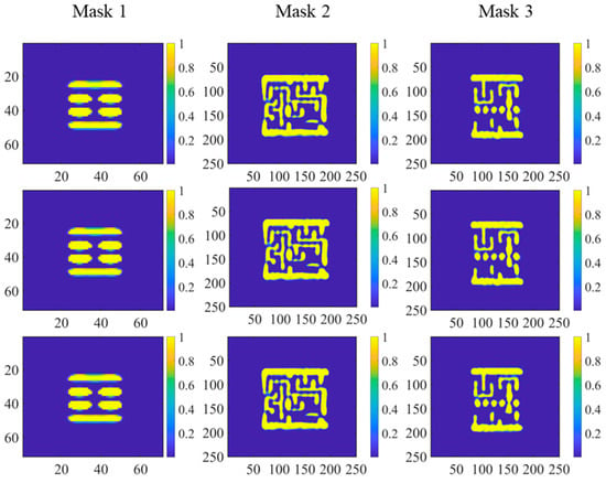
Figure 14.
Resist images of three calculations by GA-APSO.
Figure 14 shows the resist images of the three repeat calculations. Figure 15 and Figure 16 present the source and mask after SMO of the three calculations, respectively. Despite PE differences, the same pattern of source was obtained for Mask 1 and Mask 3 in the three calculations. Table 2 shows the PEs after optimization. Standard Deviation for the three masks were 0.19, 107.08, and 27.52, respectively. The results show that the algorithm has superior repeatability.
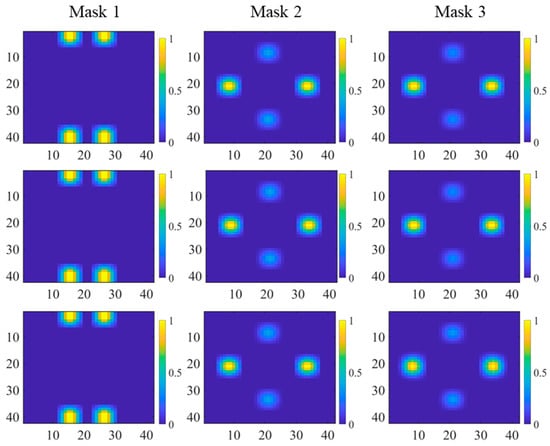
Figure 15.
Sources after SMO of three calculations by GA-APSO.
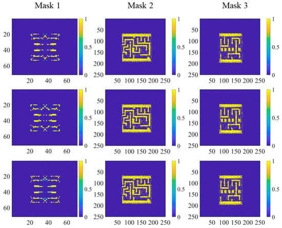
Figure 16.
Mask after SMO of three calculations by GA-APSO.

Table 2.
PEs of three calculations.
3.3. Discussion
Simulation results of SMO by GA, APSO, and GA-APSO show that all the three algorithms can improve the resist image quality. Optimization of source and mask can increase the degree of optimization freedom and achieve better resist image quality than single source optimization. After the SO step, the PEs decreased significantly during the initial iteration stage in the MO step.
The optimization results by GA, APSO, and GA-APSO reached different PEs, in which GA-APSO obtained better results and less cost. Although both GA and APSO are global optimization algorithms, their mechanisms are different. In GA, the whole population evolution by randomly crossover and mutation which has not obvious orientation. This leads to a slow optimization efficiency for GA in the later iteration stage. However, the position and velocity of particles are retained and utilized simultaneously in optimization by APSO. Personal best and global best information are shared for each particle, which has obvious orientation in optimization. This leads to fast optimization efficiency for APSO but may fall into local optima. GA-APSO combined GA and APSO. In the algorithm mechanism of GA-APSO, population is updated by APSO first and then crossover and mutation, which effectively improve the algorithm efficiency and obtain optimization result closer to the global optimal. Moreover, adaptive strategies for APSO particle updates are utilized to further improve the algorithm efficiency and global optimization capability.
4. Conclusions
In this paper, a GA-APSO algorithm was proposed to inversely obtain the global optimal distribution of the pixelated source and mask in the lithographic imaging process. The computational efficiency was improved by combining the GA and APSO algorithms. Additionally, the global search and local search were balanced through adaptive strategies, leading to a result closer to the global optimal solution. To verify the performance of GA-APSO, horizontal lines and two different complex patterns were optimized. Moreover, the simulation results are compared with optimization by GA and APSO. The results show that the PEs of the resist image optimized by GA-APSO were reduced by 40.13–52.94% and 10.28%-33.31% compared to GA and APSO, respectively. The time cost of GA-APSO was reduced by 75.91–87.00% and 48.43–58.66% compared to GA and APSO, respectively. Moreover, repeated calculation showed that the GA-APSO results were relatively stable. The results demonstrate the superior performance of GA-APSO in efficiency, accuracy, source repeatability, and mask optimization.
Author Contributions
Simulation design, J.L. and J.Z.; methodology, J.L. and J.Z.; investigation, J.L., J.Z. and H.S.; data curation, J.L., J.Z. and C.J.; writing—original draft preparation, J.L., J.Z. and J.W.; writing—review and editing, J.L., J.Z. and S.H. All authors have read and agreed to the published version of the manuscript.
Funding
The work is supported by the National Key Research and Development Plan 2021YFB3200204, and the National Natural Science Foundation of China (NSFC) under Grants No. 61604154, No. 61875201, No. 61975211, and No. 62005287, the Youth Innovation Promotion Association of the Chinese Academy of Sciences (2021380), and the project of the Western Light of Chinese Academy of Science.
Institutional Review Board Statement
Not applicable.
Informed Consent Statement
Not applicable.
Data Availability Statement
All data are included in the study.
Conflicts of Interest
The authors declare no conflict of interest.
References
- Liebmann, L.W. Resolution enhancement techniques in optical lithography: It’s not just a mask problem. In Photomask and Next-Generation Lithography Mask Technology VIII; SPIE: St Bellingham, WA, USA, 2001; Volume 4409, pp. 23–32. [Google Scholar] [CrossRef]
- Bukofsky, S. Optimum mask and source patterns to print a given shape. J. Micro/Nanolithography MEMS MOEMS 2002, 1, 13. [Google Scholar] [CrossRef]
- Chen, W.H.; He, J.F.; Dong, L.S.; Wei, Y.Y. Mechanism and Applications of Source Mask Optimization. Semicond. Technol. 2017, 42, 641–649. [Google Scholar] [CrossRef]
- Socha, R. Freeform and SMO. In Optical Microlithography XXIV; SPIE: St Bellingham, WA, USA, 2011; Volume 7973, pp. 19–35. [Google Scholar] [CrossRef]
- Jia, N.; Lam, E.Y. Pixelated source mask optimization for process robustness in optical lithography. Opt. Express 2011, 19, 19384–19398. [Google Scholar] [CrossRef] [PubMed]
- Li, J.; Lam, E.Y. Robust source and mask optimization compensating for mask topography effects in computational lithography. Opt. Express 2014, 22, 9471–9485. [Google Scholar] [CrossRef] [PubMed]
- Ma, X.; Han, C.; Li, Y.; Dong, L.; Arce, G.R. Pixelated source and mask optimization for immersion lithography. J. Opt. Soc. Am. A 2012, 30, 112–123. [Google Scholar] [CrossRef] [PubMed]
- Peng, Y.; Zhang, J.; Wang, Y.; Yu, Z. High performance source optimization using a gradient-based method in optical lithography. In Proceedings of the 2010 11th International Symposium on Quality Electronic Design (ISQED), San Jose, CA, USA, 22–24 March 2010; pp. 108–113. [Google Scholar] [CrossRef]
- Ma, X.; Dong, L.; Han, C.; Gao, J.; Li, Y.; Arce, G.R. Gradient-based joint source polarization mask optimization for optical lithography. J. Micro/Nanolithography MEMS MOEMS 2015, 14, 023504. [Google Scholar] [CrossRef]
- Yu, J.-C.; Yu, P. Gradient-based fast source mask optimization (SMO). In Optical Microlithography XXIV; SPIE: St Bellingham, WA, USA, 2011; Volume 7973, pp. 681–693. [Google Scholar] [CrossRef]
- Sivanandam, S.N. Introduction to Genetic Algorithms; Springer: Berlin/Heidelberg, Germany, 2008. [Google Scholar] [CrossRef]
- Fuhner, T.; Erdmann, A.; Schnattinger, T. Genetic algorithms for geometry optimization in lithographic imaging systems. In Applications of Digital Image Processing XXVII; SPIE: St Bellingham, WA, USA, 2004; pp. 29–40. [Google Scholar] [CrossRef]
- Erdmann, A.; Fuehner, T.; Schnattinger, T.; Tollkuehn, B. Toward automatic mask and source optimization for optical lithography. In Optical Microlithography XVII; SPIE: St Bellingham, WA, USA, 2004; pp. 646–657. [Google Scholar] [CrossRef]
- Fühner, T.; Erdmann, A.; Seifert, S. Direct optimization approach for lithographic process conditions. J. Micro/Nanolithography MEMS MOEMS 2007, 6, 031006. [Google Scholar] [CrossRef]
- Fühner, T.; Erdmann, A.; Evanschitzky, P. Simulation-based EUV source and mask optimization. In Photomask Technology; SPIE: St Bellingham, WA, USA, 2008; Volume 7122, pp. 651–664. [Google Scholar] [CrossRef]
- Yang, C.; Wang, X.; Li, S.; Erdmann, A. Source mask optimization using real-coded genetic algorithms. In Optical Microlithography XXVI; SPIE: St Bellingham, WA, USA, 2013; Volume 8683, pp. 570–583. [Google Scholar] [CrossRef]
- Navid Razmjooy, M.A.; Foroozandeh, Z. (Eds.) Metaheuristics and Optimization in Computer and Electrical Engineering; Springer: Cham, Switzerland, 2021. [Google Scholar] [CrossRef]
- Wang, L.; Li, S.; Wang, X.; Yan, G.; Yang, C. Pixelated source optimization for optical lithography via particle swarm optimization. J. Micro/Nanolithography MEMS MOEMS 2016, 15, 013506. [Google Scholar] [CrossRef]
- Zhang, Z.; Li, S.; Wang, X.; Cheng, W.; Qi, Y. Source mask optimization for extreme-ultraviolet lithography based on thick mask model and social learning particle swarm optimization algorithm. Opt. Express 2021, 29, 5448–5465. [Google Scholar] [CrossRef] [PubMed]
- Sun, H.; Du, J.; Jin, C.; Feng, J.; Wang, J.; Hu, S.; Liu, J. Global Source Optimisation Based on Adaptive Nonlinear Particle Swarm Optimisation Algorithm for Inverse Lithography. IEEE Photon-J. 2021, 13, 1–7. [Google Scholar] [CrossRef]
- Wong, A.K. Optical Imaging in Projection Microlithography; SPIE: St Bellingham, WA, USA, 2005. [Google Scholar] [CrossRef]
- Chen, G.; Li, S.; Wang, X. Source mask optimization using the covariance matrix adaptation evolution strategy. Opt. Express 2020, 28, 33371–33389. [Google Scholar] [CrossRef] [PubMed]
- Poonawala, A.; Milanfar, P. A pixel-based regularization approach to inverse lithography. Microelectron. Eng. 2007, 84, 2837–2852. [Google Scholar] [CrossRef]
Disclaimer/Publisher’s Note: The statements, opinions and data contained in all publications are solely those of the individual author(s) and contributor(s) and not of MDPI and/or the editor(s). MDPI and/or the editor(s) disclaim responsibility for any injury to people or property resulting from any ideas, methods, instructions or products referred to in the content. |
© 2023 by the authors. Licensee MDPI, Basel, Switzerland. This article is an open access article distributed under the terms and conditions of the Creative Commons Attribution (CC BY) license (https://creativecommons.org/licenses/by/4.0/).