Article

Wavelength-Tunable Pulsed Cylindrical Vector Beams in a 1.7-μm Mode-Locking Thulium-Doped All-Fiber Laser

1
China Electronics Technology Group Corporation No. 34 Research Institute, Guilin 541004, China
2
International Collaborative Laboratory of 2D Materials for Optoelectronics Science and Technology, Institute of Microscale Optoelectronics, Shenzhen University, Shenzhen 518060, China
*
Author to whom correspondence should be addressed.
These authors contributed equally to this work.
Photonics 2023, 10(10), 1163; https://doi.org/10.3390/photonics10101163
Submission received: 12 September 2023 / Revised: 11 October 2023 / Accepted: 12 October 2023 / Published: 17 October 2023
(This article belongs to the Special Issue Advances and Application of Structured Light)

Abstract

:
Because of the special absorption peak, pulsed lasers at 1.7 μm have been rapidly developed in medical treatment, biological imaging and so on. Introducing the cylindrical vector beam (CVB) may further promote these special applications due to its unique intensity, phase and polarization characteristics. Herein, we have experimentally demonstrated the generation of wavelength-tunable pulsed CVBs at 1.7 μm based on a thulium-doped all-fiber laser. A bandpass filter with a wide bandwidth combined with nonlinear polarization rotation technology is used to obtain pulsed laser emission at 1.7 μm. By taking advantage of a home-made Lyot filter and mode selective coupler (MSC), pulsed CVBs can be obtained with a wavelength tuning range of 66 nm (1720–1786 nm). The development of wavelength-tunable pulsed CVBs at the 1.7 μm waveband has significant potential applications in deep bioimaging and laser processing.

1. Introduction

In recent years, 1.7 μm lasers have received significant attention due to their unique spectral characteristics and have shown great potential in many applications. A 1.7 μm laser is close to the absorption peak of fat in biological tissues and between two water absorption peaks, leading to a greater absorption of fat compared to water. Consequently, it is extensively used in lipid-targeted skin therapy [1,2]. Furthermore, 1.7 μm ultrafast pulsed lasers exhibit weak scattering and absorption effects in biological tissues [3], making them suitable for deep bioimaging applications such as three-photon microscopy and optical coherence tomography [4,5,6]. Especially for more efficient three-photon excitation, a pulsed laser source is usually crucial. For more fluorescent indicators, a wavelength-tunable pulsed laser is the optimal solution for three-photon microscopy at 1.7 μm [7]. In addition, pulsed lasers at 1.7 μm possess several strong absorption peaks linked to resonances within O-H, C-O, and C-H bonds, rendering them important in laser welding and material processing [8,9]. By tuning the wavelength, it is possible to utilize different absorption peaks to achieve selective heating of a material.
Currently, there are two main methods to generate 1.7 μm laser emission: nonlinear frequency conversion [10,11,12] and rare-earth-doped fibers, such as bismuth-doped fibers (BDFs) [13,14] and thulium-doped fibers (TDFs) [15,16,17]. The method of nonlinear frequency conversion employs the strong nonlinear effect in the fiber to convert pump lights at another wavelength into the 1.7 μm waveband. However, this method typically adopts a high peak power femtosecond pump source, which requires a comprehensive tradeoff among the spectral characteristics, wavelength tunability and power flexibility [11]. As for bismuth-doped fiber lasers, the energy of the output pulse is typically small due to the low gains of bismuth-doped fiber at the 1.7 μm band [14]. A bismuth-doped mode-locked fiber laser with a carbon nanotube saturable absorber has been proposed for generating 1.7 μm ultrashort pulses, but the output pulse energy is only at the pJ level [18]. Additionally, the preparation technology of BDFs is not mature. Recently, the TDF has proven to be an ideal gain medium for generating a 1.7 μm laser emission due to its wide emission spectrum of 1.6–2.1 μm. To achieve laser emissions at 1.7 μm with TDF, researchers have employed short-pass filters or special fibers to suppress amplified spontaneous emission (ASE) at longer wavelengths. By using an acousto-optic tunable filter (AOTF), a thulium-doped mode-locked fiber laser in the range of 1690–1765 nm was realized [19]. But, the introduction of AOTF increases extra loss and cavity complexity. Considering the compactness of the cavity, an all-fiber thulium-doped laser with a tuning range of ~100 nm has been proposed by combining a specially designed photonic crystal fiber [20]. Subsequently, a broadband wavelength-tunable pulsed laser at 1.7 μm with a tuning range of 150 nm was achieved by using a home-made W-type TDF with normal dispersion in the laser cavity [21]. The W-type index profile exhibits the short-pass filtering effect, which allows for operating at 1.7 μm. In addition, the transmission loss of W-type TDF is very sensitive to the bending diameter, which is beneficial to the wavelength tunability in an all-fiber cavity with the fiber bending technology [21]. Nevertheless, these methods require a special design in terms of the fiber, which is costly and increases cavity complexity. Therefore, a simple, compact and economical 1.7 μm wavelength-tunable fiber laser is still an issue to be addressed.
Unlike spatially uniform polarization Gaussian beams, cylindrical vector beams (CVBs) have an axisymmetric polarization distribution with a doughnut-like intensity profile [22]. Furthermore, the CVB also shows a distinctive focusing property. Focused radially polarized CVBs have a strong electric field component along the optical axis direction with a much smaller spot size compared to the focused Gaussian beam. Thanks to these unique properties, CVBs have been widely used in stimulated emission loss microscopy, mode-division multiplexing and optical sensing [23,24,25]. Therefore, pulsed CVBs at 1.7 μm with tunable wavelengths may broaden the application scenarios of a 1.7 μm laser and promote its booming development. So far, there are several methods used to generate CVBs by using spatial elements, including spatial light modulators [26], birefringent components [27], vortex half-wave plates [28] and so on. However, for a fiber-based system, the introduction of extra spatial devices needs meticulous alignment for free-space-to-fiber coupling, which greatly increases the complexity and cost of the system. Considering the simplicity, compactness and economy of all-fiber laser systems, few-mode fiber Bragg grating (FM-FBG) and offset splicing technology have been proposed to generate CVBs [29,30]. However, these approaches frequently suffer from significant insertion loss. To further reduce loss, long-period fiber grating (LPFG) and acoustically induced fiber grating (AIFG) have been adopted for high-order mode (HOM) conversion [31,32,33]. Recently, a high-efficiency CVB fiber laser has been demonstrated by using LPFG with a slope efficiency of up to 35% [33]. Nevertheless, these methods all possess limited operating spectral bandwidths, which is definitely unsuitable for the generation of broadband tunable wavelengths.
Compared with the above methods, a mode-selective coupler (MSC) has the advantages of being low loss, all-fiber-based, having a compact size and having a wide operating bandwidth, which is a suitable solution for generating broadband wavelength-tunable pulsed CVBs in a fiber laser. To date, numerous reports have investigated the generation of CVBs using MSC in the 1 μm and 1.5 μm regions [34,35,36]. Recently, a high-energy CVB fiber laser has been proposed based on the principle of mode superposition, which can generate CVBs with an output power of 3.1 W and a mode purity of over 90% [37]. In the past, we have reported on the generation of 1.65 μm pulsed CVBs in a mode-locked Raman fiber laser by using a home-made MSC [38,39]. Very recently, by carefully optimizing the tapering diameter of fibers in the MSC, a pulsed CVB at 1.7 μm has been achieved in a thulium-doped mode-locking all-fiber laser. The duration of the pulsed CVBs is as short as 186 fs by tightly managing the intracavity dispersion to a near-zero dispersion regime [40]. However, the wavelength tunability of a 1.7 μm pulsed CVBs fiber laser has not yet been investigated.
In this paper, we have reported on a wavelength-tunable pulsed CVB fiber laser at 1.7 μm. The mode-locked operation at 1.7 μm is achieved by using a wideband bandpass filter for suppression ASE at long wavelengths and nonlinear polarization rotation (NPR) technology for mode-locking. To adjust the central wavelength of pulsed CVBs, a fiber-based Lyot filter is selected for its simple structure and low insertion loss. The implementation of a home-made MSC, consisting of single-mode fiber (SMF) and few-mode fiber (FMF), enables broadband HOM conversion. By adjusting the mode superposition of the HOM and internal polarization state, pulsed CVBs ranging from 1720 to 1786 nm can be achieved. It is worth noting that vortex beams (VBs) can also be generated under proper mode superposition. This simple and compact scheme for generating tunable pulsed CVBs at 1.7 μm has important practical applications in the field of deep imaging and material processing.

2. Experimental Setup

Here, we present a home-made MSC with a central wavelength of 1750 nm, which can efficiently convert the LP01 mode to the LP11 mode for CVBs. According to the coupled-mode theory, mode conversion occurs between SMF and FMF when the phase matching condition is met (i.e., when the mode propagation constant β1 of LP01 mode in SMF is equal to β2 of LP11 mode in FMF). The propagation constants of optical fibers are typically different. However, effective mode coupling can often be achieved through the use of pre-tapered fiber to the appropriate diameter ratio of SMF and FMF [41]. Through the finite element method [42], we calculated the mode effective index (proportional to the propagation constant β) versus fiber cladding radius for the LP01 mode in the SMF and LP11 mode in the FMF, as shown in Figure 1a. The dashed line represents the phase matching point we have chosen, indicating that the diameters of SMF and FMF are 6.4 μm and 10.8 μm, respectively. The mode effective indexes of two different modes (LP01 and LP11) are all 1.4332 with a diameter ratio (SMF to FMF) of 0.574. Once the above condition is matched, the LP01 in the SMF can be converted to the LP11 in the FMF almost completely in the coupled region marked in Figure 1b. Based on the above simulation results, we fabricated an MSC experimentally. The schematic of the 1.7 μm MSC is illustrated in Figure 1b, consisting of a SMF (8.2/125 μm, SMF-28e, Corning) and a FMF (19/125 μm, four-mode fiber, OFS).
In the experiment, the diameter of the SMF is pre-tapered to about 71.75 µm. Then, we carefully aligned the FMF and pre-tapered SMF in parallel and fused them together by using the fused biconical taper method [36] along with the power monitor. A self-built 1750 nm laser source was employed as the input port to inject the light into one end of the SMF. Two power meters connected to the other end of SMF and FMF were used to monitor the output power at both ends, ensuring the desired coupling ratio and low insertion loss. The optimal coupling efficiency and target output coupling ratio can be achieved by optimizing the pre-tapering length and the length of the coupling region. Ultimately, the home-made MSC was packaged with a heat-shrinkable tube. To achieve high energy LP11 mode output, we selected a coupling ratio of 50:50. The total insertion loss of the MSC was measured at about 1.1 dB at 1750 nm. In Figure 1d, we have measured the intensity profile of the output of the FMF port at different wavelengths. As can be seen, at a wavelength range of 1720 to 1786 nm, the conversion to LP11 mode can always be maintained, exhibiting broadband characteristics.
The schematic of the laser cavity is illustrated in Figure 1c. The gain medium is 1 m long single-mode Tm-doped fiber (SM-TSF-9/125, Nufern, East Granby, CT, USA), which is pumped by a 1570 nm commercial laser through a 1570/1750 nm wavelength division multiplexer (WDM). It is worth noting that due to the strong reabsorption effect, using Tm-doped fiber to achieve gain at shorter wavelengths (below 1800 nm) will inevitably lead to the presence of ASE at longer wavelengths [21]. Thus, a bandpass filter (BPF) centered at 1735 nm was introduced to suppress ASE at longer wavelengths (above 1800 nm). It is worth noting that the 3-dB bandwidth of the BPF was deliberately selected at 100 nm for the wide wavelength tunability. A 10 m long passive SMF (SMF-28e, Corning) was incorporated into the cavity to enhance the nonlinear effect in the cavity, which makes it easier to achieve mode-locking operation. The total length of the ring cavity was about 22.4 m. The 50% port (FMF) of the MSC was selected as the output. The in-line polarization controllers (PCs) in the cavity (PC1, PC2) were used to finely adjust the polarization state and birefringence. The in-line PC3 added on the FMF output was used to adjust the phase differences between different LP11 modes, enabling their linear superposition to achieve pulsed CVBs. A polarization-dependent isolator (PDI) at 1720 nm was chosen as the key device for mode locking.
In addition, for the wide tunable wavelength, an all-fiber Lyot filter was utilized in the cavity. It consisted of a piece of polarization maintain fiber (PMF), two polarization controllers (PC1 and PC2), and the PDI. The PMF ensures a strong birefringence effect, while the PDI induces polarization-dependent loss. Additionally, two PCs were employed to align the angle between the fast axis of the PMF and the polarization axis of the PDI. There is a linear phase difference Δφ between two orthogonal beams propagating along the fast and slow axes of PMF. The phase difference Δφ can be calculated as:
Δφ = (2π/λ)LΔn
where λ is the center wavelength, L is the length of PMF, and Δn represents the birefringence of PMF at the value of 4.0 × 10⁻⁴. The laser with phase difference is modulated by PDI to obtain a spectral filter with a comb cosine profile. The transmittance curve is given by:
T = cos2(Δφ/2)
Hence, the period of the transmission peak can be approximately written as [43]:
Δλ ≈ λ2/LΔn
Considering that our Lyot filter is equipped with a 5 cm PMF, the corresponding Δλ is around 153 nm. Since the 3-dB bandwidth (100 nm) of the band-pass filter selected above is narrower than the tuning range of our home-made Lyot filter, it is feasible to continuously tune the wavelength within the bandwidth of the band-pass filter. It is important to note that the two polarization controllers introduce a phase difference without affecting the period of the transmission peak Δλ. By adjusting the two polarization controllers, the phase difference can be changed, allowing the transmission curve of the filter to be shifted [44]. Consequently, it is possible to tune the output wavelength of the laser within a specific range.

3. Results and Discussions

In the experiment, stable single-pulse mode-locking operation could be achieved by adjusting PCs (PC1 and PC2) and increasing pump power to 878 mW. At a pump power of 1015 mW, we give out the output characteristics of a single pulse from the FMF in Figure 2. The average output power is 4.6 mW, corresponding to a single pulse energy of 0.5 nJ. Figure 2a shows the output spectrum (measured by an optical spectrum analyzer (OSA, Yokogawa, AQ6375B, Tokyo, Japan)) of mode-locking pulses with an obvious Kelly sideband. The corresponding center wavelength is at 1750.1 nm with a 3-dB bandwidth of 3.3 nm. Of course, we also give out the spectrum after transmitting a long fiber pigtail (2 m), which shows obvious intensity modulation arising from the intermodal interference. The pulse train trace (measured by a 1 GHz digital oscilloscope (Tekrtonix, MDO4104C, Beaverton, OR, USA) together with a 12.5 GHz photoelectric detector (E-O Tech. Inc., ET-5000F, Traverse City, MI, USA)) with a pulse separation of 112.3 ns is illustrated in Figure 2b, matching the fundamental repetition frequency for a ~22.4 m long laser cavity. Meanwhile, a span of 4 μs oscilloscope trace, which exhibits a highly uniform amplitude, is also presented in the inset of Figure 2b. The pulse FWHM duration is measured to be 1.01 ps (Sech2 fitting) through a commercial autocorrelator (APE, PulseCheck 150 USB, Berlin, Germany), as demonstrated in Figure 2c. Figure 2d depicts the radio frequency (RF) spectrum; it shows a high signal-to-noise ratio (SNR) of 60.4 dB at the fundamental frequency of 8.901 MHz. Furthermore, the insert represents a wider RF spectrum span of 1 GHz, in which there are no other redundant frequency components except mode-locking. All these highlight the high stability of the mode-locking state.
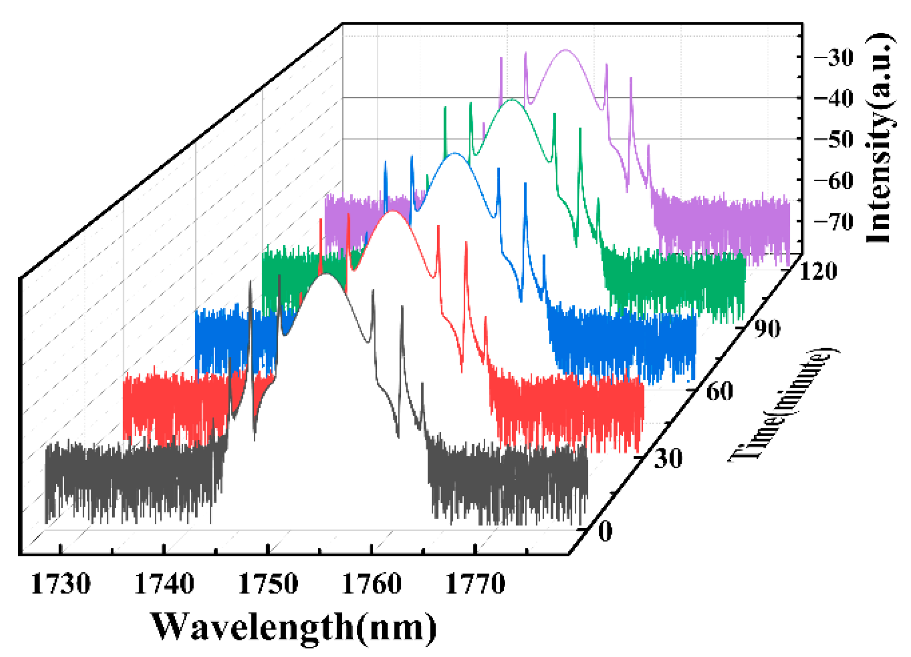
With the increase in pump power, the pulse will become unstable. Specifically, the pulse will split when the pump power reaches 1030 mW. However, reducing pump power can restore the stable single-pulse train. The mode-locking state disappears when the pump power decreases to 856 mW. In the process of changing the pump power, when the pulse is unstable, it can be re-stabilized by slightly tuning the PCs. To further investigate the long-term stability of the output pulse, we kept the pump power unchanged in a stable mode-locked state and measured the optical spectral every 30 min. As shown in Figure 3, the optical spectral in the mode-locked state remains nearly unchanged with the passage of time, showing the excellent long-term stability of our mode-locked fiber laser. Additionally, our fiber laser can easily self-start when the pump power surpasses the mode-locked threshold.
The intensity distribution of the beam output from the laser cavity is recorded using a CCD camera (Spiricon, BGS-USB-SP928-OSI, Logan, UT, USA). Note that the LP11 mode is composed of four vector modes with approximate effective refractive indexes in FMF, including HE 21 even / odd , TM01 and TE01 modes. Among them, the HE 21 even and HE 21 odd modes possess identical mode effective refractive indexes, while the mode effective refractive indexes of the TM01 and TE01 modes are not the same. TM01 and TE01 modes are commonly recognized as radially and azimuthally polarized CVBs, respectively [28]. Consequently, extracting TM01 or TE01 modes from high-order modes proves to be a productive approach to obtaining CVBs in fiber lasers. Here, the TM01 or TE01 mode can be achieved via the linear superposition of two LP11 modes (two orthogonal modes with different intensity directions) [39]:
TM 01 = LP 11 a x + LP 11 b y TE 01 = LP 11 b x + LP 11 a y
where x/y represents the polarization direction and a/b represents the intensity distribution in the horizontal and vertical direction. It is worth noting that the phase difference between the LP11 modes should be 2mπ (m = 0, 1, 2, …) for CVBs. By squeezing and twisting the few-mode fiber, the phase difference between the LP11 modes can be effectively modified [45].
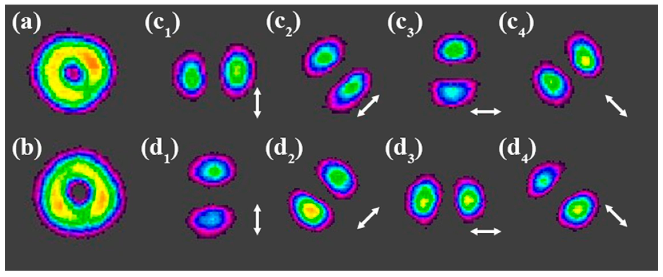
In the experiment, we keep the inter-cavity condition unchanged and slightly adjust the PC3 outside the cavity. When the phase difference between the two linear polarization modes is modified to 2 mπ, the pulsed CVBs are obtained. Figure 4a,b shows the typical intensity distributions of our pulsed CVBs with a doughnut-like shape. In order to manifest the vector characteristics of the CVBs, a Glan polarizing prism is inserted between the FMF output and the CCD camera. The intensity distribution splits to a two-lobe-like profile, which is a typical property of CVBs. In Figure 4(c1–c4), we give out the different intensity distributions along with the rotation of the Glan prism. As seen, the two-lobe-like profiles are always parallel to the polarization axis (the white arrow), which proves that they are azimuthally polarized pulsed CVBs. While in Figure 4(d1–d4), the profiles are always perpendicular to the white arrow, revealing that they are radially polarized pulsed CVBs at this moment. By using the tight bending method, the mode purity of the azimuthally and radially polarized CVBs can be measured to be 90.5% and 92.7%, respectively [46]. To examine the stability of our pulsed CVBs, we adjusted the distance between the CCD and the FMF output port from 10 cm to 1 m. Surprisingly, the intensity distribution of the CVBs basically remains unchanged.
In addition, the pulsed vortex beams (VBs) can also be generated via the superposition of the modes. Typically, circularly polarized VBs can be formed by combining HE 21 even and HE 21 odd modes linearly with a phase difference of ±π/2 due to the same propagation constant. However, this is only applicable for the continuous wave with narrow spectral bandwidth [47]. For picosecond pulses with broad spectral bandwidth, linearly polarized VBs can be generated via the linear superposition of two related LP11 modes (different intensity directions with the same polarization direction) [40]:
V ± 1 x = LP 11 a x ± i LP 11 b x V ± 1 y = LP 11 b y ±   i LP 11 a y
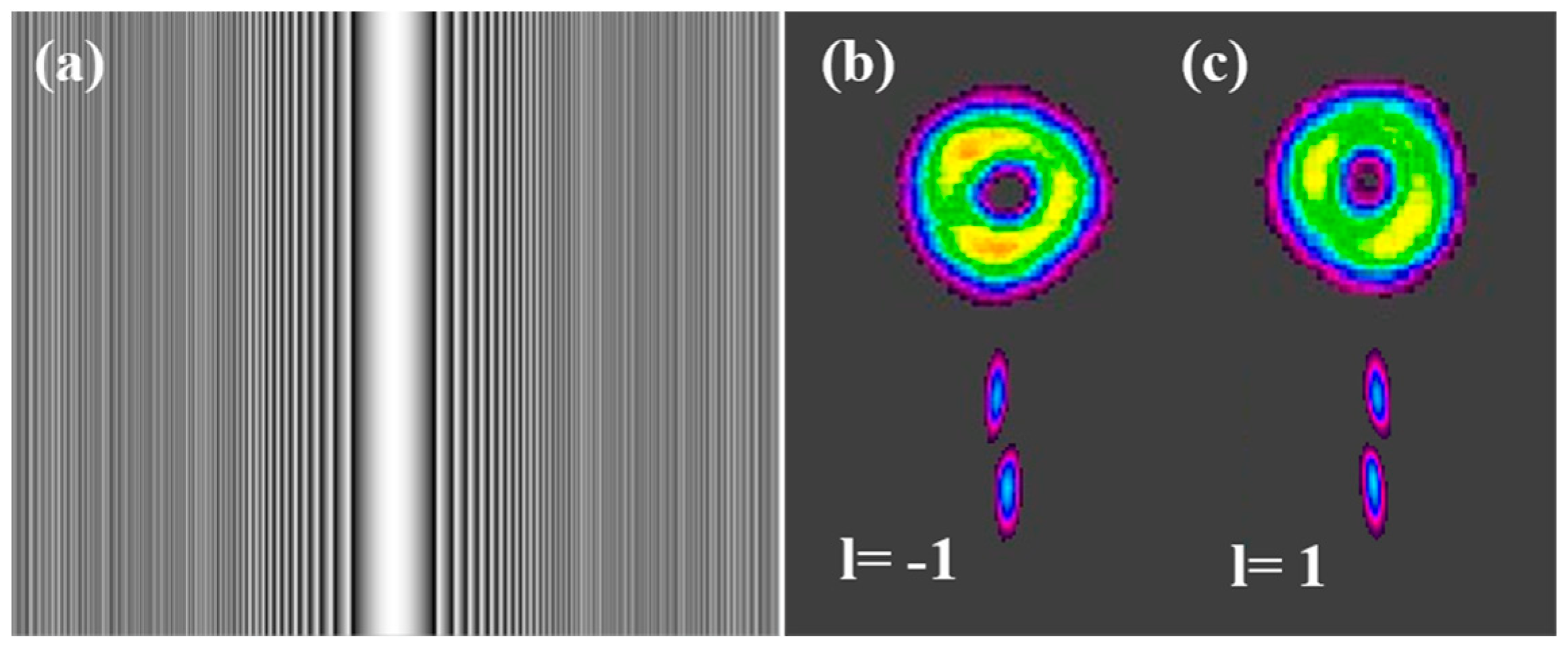
where V ± 1 x and V ± 1 y represent the linearly polarized VBs with a topological charge of ±1 in the x-polarization and y-polarization, respectively. Once the phase difference between the two LP11 modes is ±π/2, linearly polarized VBs can be obtained. So, after appropriately adjusting the PC3, pulsed VBs can also be achieved. Similarly, it also presents with a doughnut-shaped profile, as shown in Figure 5b,c. Then we designed a phase pattern (typical cylindrical lens (Figure 5a) in the SLM (Hamamatsu, X13138-SPL) to identify the topological charge of our pulsed VBs. After diffracting from the SLM, the intensity distribution shows a tilted stripe, as shown in the bottom of Figure 5b,c. When the stripe tilts to the left, the topological charge is 1, while it is −1 when it tilts to the right. Furthermore, we also verified the polarization characteristics of the pulsed VBs by introducing a polarizer after the FMF output. The mode purity of pulsed VBs with −1 and +1 topological charges were measured as being 92.5% and 90.8%, respectively.
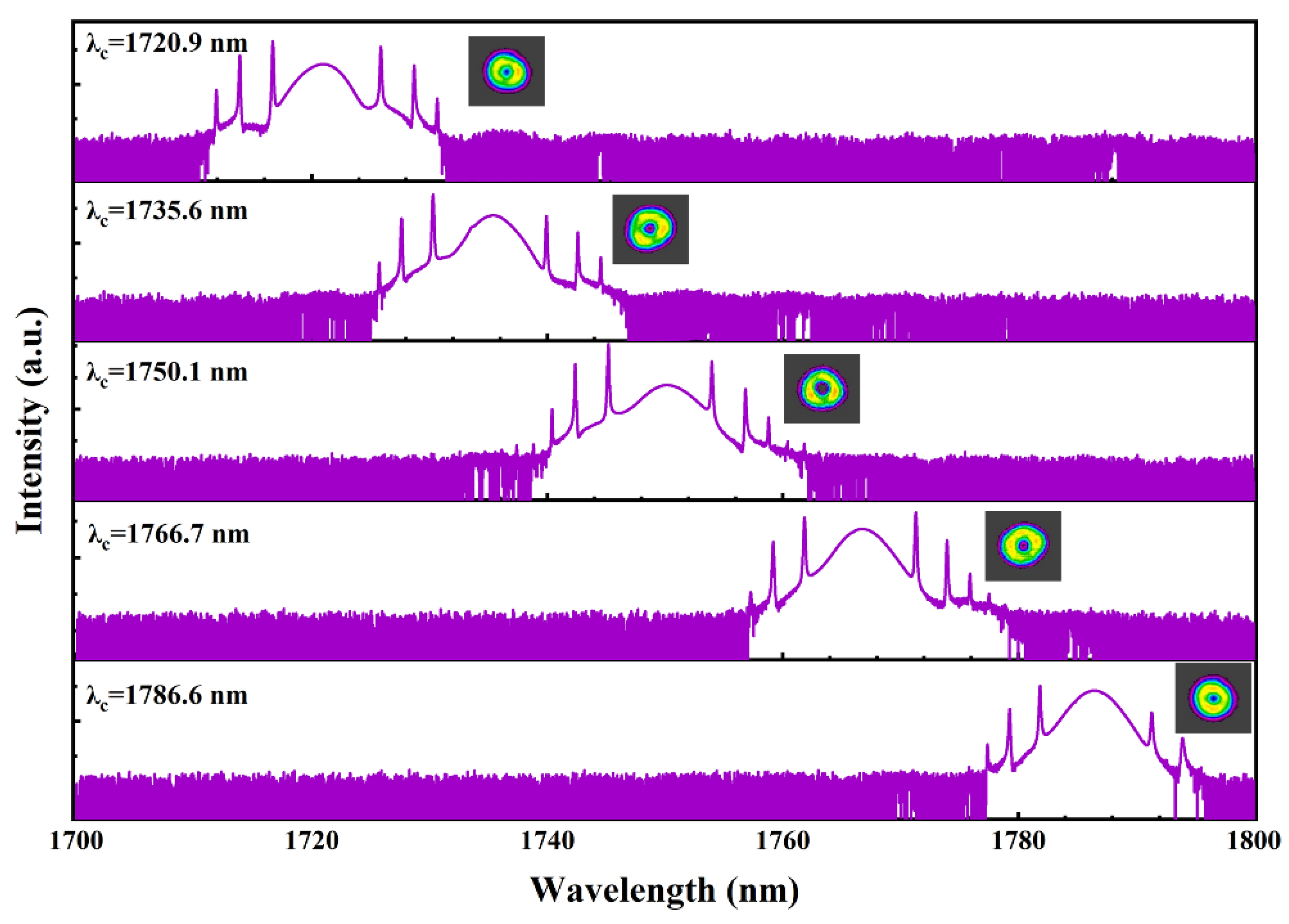
Most importantly, by taking advantage of the tunable characteristics of Lyot filters [44,48], the lasing wavelength of the pulsed CVBs can be widely tuned. By carefully adjusting PC1 and PC2, the wavelength of mode-locking pulsed CVBs can be tuned from 1720.9 nm to 1786.6 nm (range of 65.7 nm), as shown in Figure 6. The mode-locking operation cannot be achieved at longer wavelengths due to the limitations of the bandpass filter (1735 ± 50 nm). Simultaneously, the shorter waveband (below 1700 nm) is at the edge of the TDF gain bandwidth, resulting in a significant loss. Thus, the use of a broader bandwidth bandpass filter and higher-power optical fiber devices may further broaden the wavelength tuning range. During the whole tuning range process, the intensity distributions of the pulsed CVBs only change a little. Even if the change becomes large, the state of CVBs can still be retained by properly adjusting PC3 at the desired wavelength. The pulse durations measured at different wavelengths are all around 1.1 ps. Moreover, it should be noted that the average out power at all generation wavelengths is lower than 5 mW because of the polarization-dependent loss from the Lyot filter.

4. Conclusions

In conclusion, we have demonstrated an all-fiber mode-locked laser working at 1.7 μm for generating tunable pulsed CVBs by utilizing a home-made MSC and a fiber-based Lyot filter. By simply superposing two specific LP11 modes, pulsed CVBs with a wavelength tuning range of 1720–1786 nm are obtained at a repetition rate of 8.9 MHz. At 1750 nm, a stable pulse with a single pulse energy of 0.5 nJ is obtained with a pulse width of 1.01 ps. The output pulse has a signal-to-noise ratio greater than 60 dB and exhibits high stability. In addition, the pulsed VBs with the topological charge of ±1 can also be obtained by appropriately adjusting the phase difference between the related LP11 modes. The insertion loss of the fiber devices and the bandwidth of the bandpass filter can be further optimized to achieve a higher output power and wider tuning range. This work provides guidance for further investigations of wavelength-tunable pulsed CVBs at 1.7 μm waveband, which is useful for deep tissue imaging and laser processing.

Author Contributions

Conceptualization, X.Y. and R.L.; methodology, X.Y., R.L. and Y.C.; software, R.L.; validation, X.Y. and R.L.; investigation, Y.X., H.L. and J.W.; writing, original draft preparation, X.Y. and R.L.; writing, review and editing, R.L., Y.X. and J.W.; supervision, X.Y. and Y.C.; project administration, Y.C. All authors have read and agreed to the published version of the manuscript.

Funding

This work was funded by the National Natural Science Foundation of China (62271332, 62275162, 11604095), Guangdong Basic and Applied Basic Research Foundation (2023A1515030152), Major Special Projects in Guilin 2022 (20220101) and Shenzhen Government’s Plan of Science and Technology (JCYJ20190808150205481).

Data Availability Statement

Data underlying the results presented in this paper are not publicly available at this time but may be obtained from the authors upon reasonable request.

Conflicts of Interest

The authors declare no conflict of interest.

References

  1. Anderson, R.R.; Farinelli, W.; Laubach, H.; Manstein, D.; Yaroslavsky, A.N.; Gubeli, J.; Jordan, K.; Neil, G.R.; Shinn, M.; Chandler, W.; et al. Selective photothermolysis of lipid-rich tissues: A free electron laser study. Lasers Surg. Med. 2006, 38, 913–919. [Google Scholar] [CrossRef] [PubMed]
  2. Alexander, V.V.; Ke, K.; Xu, Z.; Islam, M.N.; Freeman, M.J.; Pitt, B.; Welsh, M.J.; Orringer, J.S. Photothermolysis of sebaceous glands in human skin ex vivo with a 1708 nm Raman fiber laser and contact cooling. Lasers Surg. Med. 2011, 43, 470–480. [Google Scholar] [CrossRef] [PubMed]
  3. Sordillo, L.A.; Pu, Y.; Pratavieira, S.; Budansky, Y.; Alfano, R.R. Deep optical imaging of tissue using the second and third near-infrared spectral windows. J. Biomed. Opt. 2014, 19, 056004. [Google Scholar] [CrossRef] [PubMed]
  4. Horton, N.G.; Wang, K.; Kobat, D.; Clark, C.G.; Wise, F.W.; Schaffer, C.B.; Xu, C. In vivo three-photon microscopy of subcortical structures within an intact mouse brain. Nat. Photonics 2013, 7, 205–209. [Google Scholar] [CrossRef]
  5. Yamanaka, M.; Teranishi, T.; Kawagoe, H.; Nishizawa, N. Optical coherence microscopy in 1700 nm spectral band for high-resolution label-free deep-tissue imaging. Sci. Rep. 2016, 6, 31715. [Google Scholar] [CrossRef]
  6. Chong, S.P.; Merkle, C.W.; Cooke, D.F.; Zhang, T.; Radhakrishnan, H.; Krubitzer, L.; Srinivasan, V.J. Noninvasive, in vivo imaging of subcortical mouse brain regions with 1.7 μm optical coherence tomography. Opt. Lett. 2015, 40, 4911–4914. [Google Scholar] [CrossRef]
  7. Xu, C.; Wise, F.W. Recent Advances in Fiber Lasers for Nonlinear Microscopy. Nat. Photonics 2013, 7, 875–882. [Google Scholar] [CrossRef]
  8. Wang, P.; Wang, H.W.; Sturek, M.; Cheng, J.X. Bond-selective imaging of deep tissue through the optical window between 1600 and 1850 nm. J. Biophotonics 2012, 5, 25–32. [Google Scholar] [CrossRef]
  9. Daniel, J.M.; Simakov, N.; Tokurakawa, M.; Ibsen, M.; Clarkson, W.A. Ultra-short wavelength operation of a thulium fibre laser in the 1660–1750 nm wavelength band. Opt. Express 2015, 23, 18269–18276. [Google Scholar] [CrossRef]
  10. Szewczyk, O.; Pala, P.; Tarnowski, K.; Olszewski, J.; Senna Vieira, F.; Lu, C.; Foltynowicz, A.; Mergo, P.; Sotor, J.; Sobon, G.; et al. Dual-Wavelength Pumped Highly Birefringent Microstructured Silica Fiber for Widely Tunable Soliton Self-Frequency Shift. J. Light. Technol. 2021, 39, 3260–3268. [Google Scholar] [CrossRef]
  11. Fang, X.; Wang, Z.; Zhan, L. Efficient generation of all-fiber femtosecond pulses at 1.7 μm via soliton self-frequency shift. Opt. Eng. 2017, 56, 046107. [Google Scholar] [CrossRef]
  12. Li, J.; Li, H.; Wang, Z. Application of Hollow-Core Photonic Crystal Fibers in Gas Raman Lasers Operating at 1.7 μm. Crystals 2021, 11, 121. [Google Scholar] [CrossRef]
  13. Khegai, A.; Melkumov, M.; Riumkin, K.; Khopin, V.; Firstov, S.; Dianov, E. NALM-based bismuth-doped fiber laser at 1.7 μm. Opt. Lett. 2018, 43, 1127–1130. [Google Scholar] [CrossRef] [PubMed]
  14. Firstov, S.; Alyshev, S.; Melkumov, M.; Riumkin, K.; Shubin, A.; Dianov, E. Bismuth-doped optical fibers and fiber lasers for a spectral region of 1600–1800 nm. Opt. Lett. 2014, 39, 6927–6930. [Google Scholar] [CrossRef]
  15. Zhang, L.; Zhang, J.; Sheng, Q.; Fu, S.; Shi, W.; Yao, J. High-efficiency Thulium-doped fiber laser at 1.7 μm. Opt. Laser Technol. 2022, 152, 108180. [Google Scholar] [CrossRef]
  16. Quan, X.; Ma, R.; Wu, H.; Yong Bai, Z.; Yuan Fan, D.; Liu, J. Low threshold and high spectral purity 1.7 μm random fiber laser based on hybrid gain. Opt. Laser Technol. 2022, 155, 108410. [Google Scholar] [CrossRef]
  17. Xiao, X.; Guo, H.; Yan, Z.; Wang, H.; Xu, Y.; Lu, M.; Wang, Y.; Peng, B. 3 W narrow-linewidth ultra-short wavelength operation near 1707 nm in thulium-doped silica fiber laser with bidirectional pumping. Appl. Phys. B 2017, 123, 135. [Google Scholar] [CrossRef]
  18. Noronen, T.; Firstov, S.; Dianov, E.; Okhotnikov, O.G. 1700 nm dispersion managed mode-locked bismuth fiber laser. Sci. Rep. 2016, 6, 24876. [Google Scholar] [CrossRef]
  19. Li, C.; Shi, J.; Gong, X.; Kong, C.; Luo, Z.; Song, L.; Wong, K.K.Y. 1.7 μm wavelength tunable gain-switched fiber laser and its application to spectroscopic photoacoustic imaging. Opt. Lett. 2018, 43, 5849–5852. [Google Scholar] [CrossRef]
  20. Emami, S.D.; Dashtabi, M.M.; Lee, H.J.; Arabanian, A.S.; Rashid, H.A.A. 1700 nm and 1800 nm band tunable thulium doped mode-locked fiber lasers. Sci. Rep. 2017, 7, 12747. [Google Scholar] [CrossRef]
  21. Chen, S.; Chen, Y.; Liu, K.; Sidharthan, R.; Li, H.; Chang, C.J.; Wang, Q.J.; Tang, D.; Yoo, S. All-fiber short-wavelength tunable mode-locked fiber laser using normal dispersion thulium-doped fiber. Opt. Express 2020, 28, 17570–17580. [Google Scholar] [CrossRef] [PubMed]
  22. Wang, X.; Song, Y.; Pang, F.; Li, Y.; Zhang, Q.; Yang, Y.; Chang, B.; Ju, Y. All-Fiber Cylindrical Vector Beams Multiplexing Through a Mode-Selective Coupler. IEEE J. Quantum Electron. 2019, 55, 1–8. [Google Scholar] [CrossRef]
  23. Yan, L.; Kristensen, P.; Ramachandran, S. Vortex fibers for STED microscopy. APL Photonics 2019, 4, 022903. [Google Scholar] [CrossRef]
  24. Yang, J.; Liu, H.; Wen, J.; Chen, L.; Shang, Y.; Chen, N.; Huang, S.; Wang, T.; Pang, F. Cylindrical vector modes based Mach-Zehnder interferometer with vortex fiber for sensing applications. Appl. Phys. Lett. 2019, 115, 051103. [Google Scholar] [CrossRef]
  25. Xie, Z.; Gao, S.; Lei, T.; Feng, S.; Zhang, Y.; Li, F.; Zhang, J.; Li, Z.; Yuan, X.J.P.R. Integrated (de)multiplexer for orbital angular momentum fiber communication. Photonics Res. 2018, 6, 743. [Google Scholar] [CrossRef]
  26. Forbes, A.; Dudley, A.; McLaren, M. Creation and detection of optical modes with spatial light modulators. Adv. Opt. Photonics 2016, 8, 200–227. [Google Scholar] [CrossRef]
  27. Thirugnanasambandam, M.P.; Senatsky, Y.; Ueda, K.-i. Generation of radially and azimuthally polarized beams in Yb:YAG laser with intra-cavity lens and birefringent crystal. Opt. Express 2011, 19, 1905–1914. [Google Scholar] [CrossRef]
  28. Qi, J.; Wang, W.; Shi, B.; Zhang, H.; Shen, Y.; Deng, H.; Pu, W.; Liu, X.; Shan, H.; Ma, X.; et al. Concise and efficient direct-view generation of arbitrary cylindrical vector beams by a vortex half-wave plate. Photonics Res. 2021, 9, 803. [Google Scholar] [CrossRef]
  29. Liu, T.; Chen, S.-P.; Hou, J. Selective transverse mode operation of an all-fiber laser with a mode-selective fiber Bragg grating pair. Opt. Lett. 2016, 41, 5692–5695. [Google Scholar] [CrossRef]
  30. Li, L.; Wang, M.; Liu, T.; Leng, J.; Zhou, P.; Chen, J. High-power, cladding-pumped all-fiber laser with selective transverse mode generation property. Appl. Opt. 2017, 56, 4967–4970. [Google Scholar] [CrossRef]
  31. Li, Y.; Hao, X.; An, Y.; Zhu, Y.; Yao, T.; Zeng, X.; Zhou, P. Hundred-watt level high-order mode all-fiberized random distributed feedback Raman fiber laser with high mode purity. Chin. Opt. Lett. 2023, 21, 021406. [Google Scholar] [CrossRef]
  32. Wang, S.; Liu, X.; Wang, H.; Hu, G. High-order mode fiber laser based on few-mode fiber gratings. Opt. Laser Technol. 2022, 155, 108416. [Google Scholar] [CrossRef]
  33. Chen, R.; Wang, J.; Zhang, X.; Wang, A.; Ming, H.; Li, F.; Chung, D.; Zhan, Q. High efficiency all-fiber cylindrical vector beam laser using a long-period fiber grating. Opt. Lett. 2018, 43, 755–758. [Google Scholar] [CrossRef]
  34. Wan, H.; Wang, J.; Shen, Z.; Chen, Y.; Zhang, Z.; Wang, P.; Zhang, L. All fiber actively Q-switched Yb-doped laser with radially/azimuthally polarized beam generation. Laser Phys. Lett. 2018, 15, 095102. [Google Scholar] [CrossRef]
  35. Wang, L.; Xu, J.; Lu, J.; Teng, L.; Luo, Z.; Pang, F.; Zeng, X. 3 W average-power high-order mode pulse in dissipative soliton resonance mode-locked fiber laser. Nanophotonics 2021, 10, 3527–3539. [Google Scholar] [CrossRef]
  36. Wan, H.; Wang, J.; Zhang, Z.; Cai, Y.; Sun, B.; Zhang, L. High efficiency mode-locked, cylindrical vector beam fiber laser based on a mode selective coupler. Opt. Express 2017, 25, 11444–11451. [Google Scholar] [CrossRef] [PubMed]
  37. Liu, X.; Zhang, Y.; Dong, Z.; Lv, J.; Dai, C.; Luo, J.; Lu, Y.; Ma, X.; Lin, J.; Yao, P.; et al. High-power cylindrical vector beam fiber laser based on an all-polarization-maintaining structure. Opt. Express 2022, 30, 27123–27131. [Google Scholar] [CrossRef]
  38. Huang, M.; Wu, J.; Hong, J.; Lei, H.; Zhao, C.; Chen, Y.; Fan, D. High energy switchable pulsed High-order Mode beams in a mode-locking Raman all-fiber laser with high efficiency. Opt. Express 2021, 29, 40538–40546. [Google Scholar] [CrossRef]
  39. Wu, J.; Lai, Z.; Zhou, Y.; Xie, Y.; Lei, H.; Liu, D.; Li, N.; Zhao, C.; Fan, D.; Chen, Y. High Energy Singular Beams Generation From a Dissipative Soliton Resonance Raman Fiber Laser. J. Light. Technol. 2023, 41, 5091–5096. [Google Scholar] [CrossRef]
  40. Xie, Y.; Long, R.; Ma, Z.; Shi, Y.; Hong, J.; Wu, J.; Zhao, C.; Fan, D.; Chen, Y. 1.7 μm sub-200 fs vortex beams generation from a thulium-doped all-fiber laser. Opt. Express 2023, 31, 27858–27867. [Google Scholar] [CrossRef]
  41. Huang, Y.; Shi, F.; Wang, T.; Liu, X.; Zeng, X.; Pang, F.; Wang, T.; Zhou, P. High-order mode Yb-doped fiber lasers based on mode-selective couplers. Opt. Express 2018, 26, 19171–19181. [Google Scholar] [CrossRef] [PubMed]
  42. Zhao, A.P.; Cvetkovic, S.R.; Punjani, M. Analysis of stripe multilayer waveguides with effective index and finite element methods. IEEE J. Quantum Electron. 1992, 28, 573–579. [Google Scholar] [CrossRef]
  43. Özgören, K.; Ilday, F.Ö. All-fiber all-normal dispersion laser with a fiber-based Lyot filter. Opt. Lett. 2010, 35, 1296–1298. [Google Scholar] [CrossRef] [PubMed]
  44. Luo, X.; Tuan, T.H.; Saini, T.S.; Nguyen, H.P.T.; Suzuki, T.; Ohishi, Y. Tunable and switchable all-fiber dual-wavelength mode locked laser based on Lyot filtering effect. Opt. Express 2019, 27, 14635–14647. [Google Scholar] [CrossRef]
  45. Dong, Z.; Zhang, Y.; Li, H.; Tao, R.; Gu, C.; Yao, P.; Zhan, Q.; Xu, L. All-fiber cylindrical vector beams laser based on the principle of mode superposition. Opt. Laser Technol. 2021, 139, 106965. [Google Scholar] [CrossRef]
  46. Sun, B.; Wang, A.; Xu, L.; Gu, C.; Lin, Z.; Ming, H.; Zhan, Q. Low-threshold single-wavelength all-fiber laser generating cylindrical vector beams using a few-mode fiber Bragg grating. Opt. Lett. 2012, 37, 464–466. [Google Scholar] [CrossRef] [PubMed]
  47. Mao, D.; Zheng, Y.; Zeng, C.; Lu, H.; Wang, C.; Zhang, H.; Zhang, W.; Mei, T.; Zhao, J.J.A.P. Generation of polarization and phase singular beams in fibers and fiber lasers. Adv. Photonics 2021, 3, 014002. [Google Scholar] [CrossRef]
  48. Liu, S.; Yan, F.; Ting, F.; Zhang, L.; Bai, Z.; Han, W.; Zhou, H. Multi-Wavelength Thulium-Doped Fiber Laser Using a Fiber-Based Lyot Filter. IEEE Photonics Technol. Lett. 2016, 28, 864–867. [Google Scholar] [CrossRef]
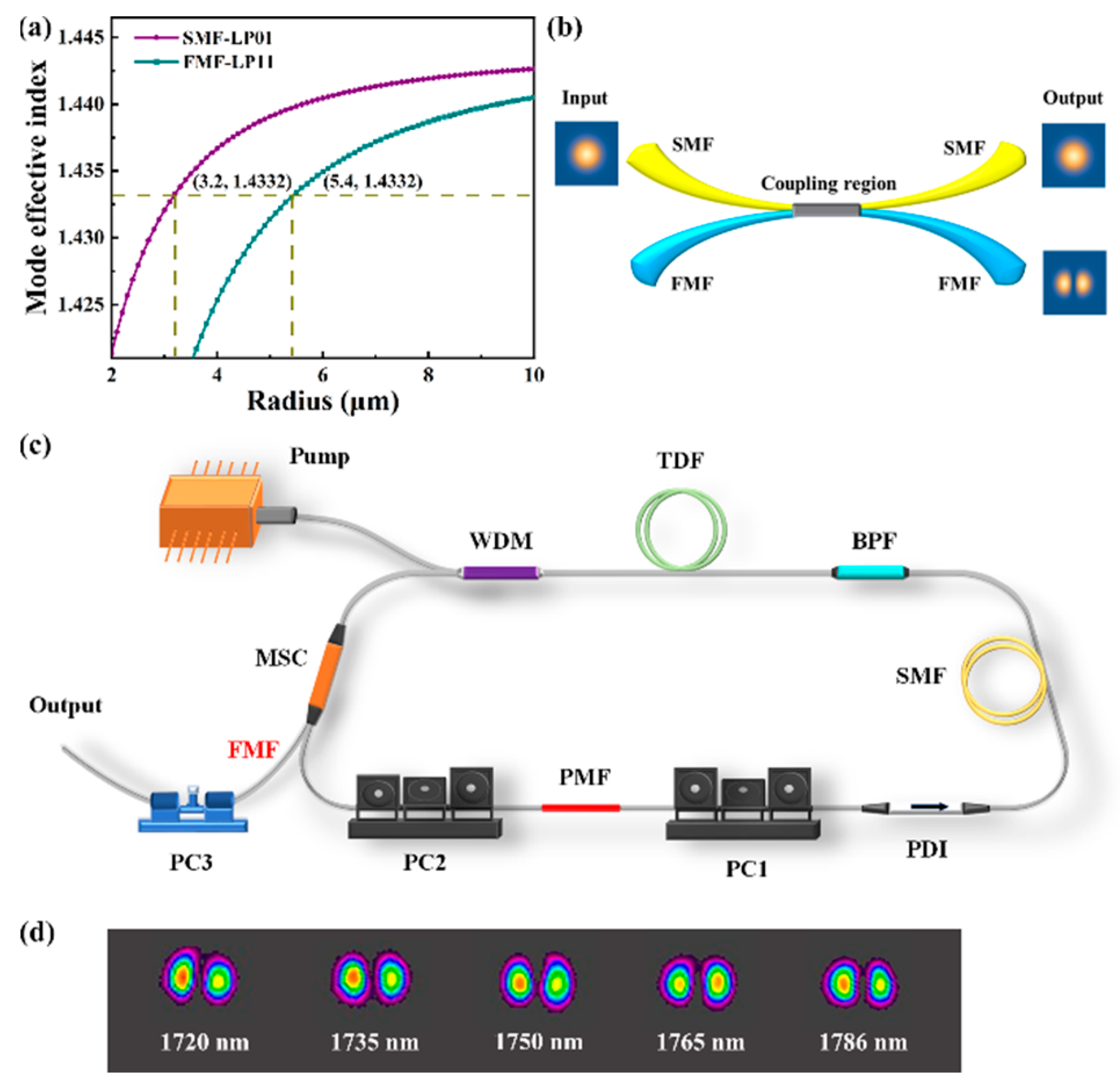
Figure 1. (a) Mode effective index with different fiber cladding radius at 1750 nm for SMF and FMF; (b) schematic of the MSC; (c) schematic of mode-locking all-fiber laser setup. WDM: wavelength division multiplexer; TDF: Tm-doped fiber; BPF: bandpass filter; SMF: single-mode fiber; PDI: polarization-dependent isolator; PC: polarization controller; PMF: polarization maintain fiber; MSC: mode-selective coupler. (d) Intensity profile of LP11 mode at different wavelengths.
Photonics 10 01163 g001
Figure 2. Output characteristics of stable single-pulse mode-locking operation. (a) spectrum; (b) pulse train; (c) pulse duration; (d) RF spectrum, inset: RF spectrum with 1 GHz span.
Photonics 10 01163 g002
Figure 3. Long-term stability of the spectrum in the mode-locking state.
Photonics 10 01163 g003
Figure 4. Near-field intensity distributions of pulsed CVBs in the single-pulse mode-locking operation. (a) azimuthally polarized CVBs; (b) radially polarized CVBs; (c,d) the different intensity distributions along with the rotation of the Glan prism.
Photonics 10 01163 g004
Figure 5. Near-field intensity distributions of pulsed VBs in single-pulse mode-locking operation. (a) A phase image of cylindrical lens; (b,c) VBs with topological charges of ±1.
Photonics 10 01163 g005
Figure 6. Wavelength-tunable pulsed CVBs in single-pulse mode-locking operation.
Photonics 10 01163 g006
Disclaimer/Publisher’s Note: The statements, opinions and data contained in all publications are solely those of the individual author(s) and contributor(s) and not of MDPI and/or the editor(s). MDPI and/or the editor(s) disclaim responsibility for any injury to people or property resulting from any ideas, methods, instructions or products referred to in the content.