Article

Fabrication of High-Performance Nanofiltration Membrane Using Polydopamine and Carbon Nitride as the Interlayer

1
School of Materials Science and Engineering, East China University of Science and Technology, Shanghai 200237, China
2
School of Chemical Engineering, Qinghai University, Xining 810016, China
3
School of Chemical and Environment Engineering, China University of Mining and Technology, Beijing 100083, China
*
Authors to whom correspondence should be addressed.
Separations 2022, 9(7), 180; https://doi.org/10.3390/separations9070180
Submission received: 15 June 2022 / Revised: 10 July 2022 / Accepted: 15 July 2022 / Published: 18 July 2022
(This article belongs to the Section Materials in Separation Science)

Abstract

:
In order to recover lithium from brine with a high Mg2+/Li+ ratio, a positively charged nanofiltration (NF) membrane was prepared by depositing polydopamine (PDA)-coated graphitic carbon nitride (g-C3N4) as the interlayer (PDA-g-C3N4) and the interfacial polymerization (IP) of polyethyleneimine (PEI) and trimesoyl chloride (TMC) was carried out. Under optimal conditions, the water contact angle of the composite membrane is only 55.5° and the isoelectric point (IEP) is 6.01. The final positively charged NF membrane (M5) exhibits high permeance (10.19 L·m−2·h−1·bar−1) and high rejection of Mg2+ (98.20%) but low rejection of Li+ (13.33%). The separation factor (SF) is up to 48.08, and the Mg2+/Li+ ratio of the permeate is 0.036 in the simulated brine. In conclusion, the M5 membrane shows a good separation performance for salt lake brine (SF = 12.79 and Mg2+/Li+ ratio of the permeate = 1.43) and good fouling resistance. Therefore, the positively charged M5 membrane with PDA-g-C3N4 as the interlayer has the potential to be used for the recovery of lithium from brine.

1. Introduction

Lithium is known as “an energy metal in the 21st century” and its demand in the energy field, e.g., as batteries and nuclear energy, has been increasing in recent years [1,2,3]. Statistics reveal that over 60% of lithium reserves are present in continental brine [4], which highlights the importance of developing more efficient technology for the recovery of lithium from brine [5,6,7]. Very often, brine is heavily loaded with Mg2+ in comparison to Li+ because of their similar ionic properties, which undoubtedly makes it more difficult for recovery of lithium from the brine. Membrane separation is considered one of the most competitive separation technologies owing to its simplicity, low cost, high energy efficiency, and eco-friendliness [8,9]. Especially nanofiltration (NF), as a pressure-driven membrane separation process, has been extensively utilized in wastewater treatment and the recovery of highly-valued products [10]. Compared to conventional separation methods, such as precipitation, chromatography, ion exchange, and liquid–liquid extraction, NF is more effective in separating lithium from brine with a high Mg2+/Li+ ratio, due to the special mono-/divalent ion separation [11]. For example, Somrani et al. studied the recovery of lithium from salt lake brine by NF and low-pressure RO membrane [12]. Sun et al. studied the separation of Li+ and Mg2+ from brine using a desalination NF membrane [13]. Their results indicated that the structural and surface properties of NF membrane play a crucial role in the separation performance [14]. There is also evidence that a positively charged NF membrane is more desirable for the removal of multivalent cations [15,16].
Nowadays, thin-film composite (TFC) membranes consisting of a dense thin film layer and a porous support layer are the primary configuration for NF membranes. These TFC membranes are usually prepared via interfacial polymerization (IP) that is highly controllable and practicable [17,18]. A positively charged polyamide (PA) TFC membrane has been successfully prepared from the reaction of polyethyleneimine (PEI), an amine-containing monomer, with trimesoyl chloride (TMC) by IP process [19]. Previous studies suggest that the physical and chemical properties of substrates, which normally are commercial ultrafiltration (UF) membranes, have important effects on the formation of the PA layer and the performance of resultant membranes. Nevertheless, the surfaces of most commercial UF membranes (e.g., polyether sulfone (PES) UF membrane) are hydrophobic with relatively low porosity, which may have an impact on the adsorption and penetration of amine monomers on the substrate and thus reduce the adhesion between the PA layer and the substrate. As a result, the resultant NF membranes may have low water permeance and are susceptible to fouling [20,21,22].
In order to solve these problems, an interlayer is proposed to modify the substrate to form a modified PA TFC membrane with a sandwich structure, which can increase the hydrophilicity, permeance, and the separation performance of membranes. Dopamine (DA) deposition is a new and promising surface modification method because of mild conditions and simple processes, and it can be carried out in weakly alkaline solutions at air atmosphere and room temperature [23]. Notably, this process has universal applicability to substrates and does not affect the functionalization of substrates [24]. Polydopamine (PDA) as the interlayer can enhance the stability and compatibility of the separation layer with the base membrane. Nanocomposite technology has attracted much attention in modulating the structural and physicochemical properties of membranes, such as hydrophilicity, fouling resistance, porosity, charge density, chemical, and thermal and mechanical stability [25]. Graphitic carbon nitride (g-C3N4) is a new type of two-dimensional nanosheets material with a graphene-like layered structure, large specific surface area, and visible light absorption. Due to its special tri-s-triazine structural unit, it also has excellent mechanical, thermal, and chemical stability and photodegradability [26,27]. More importantly, g-C3N4 is easy to prepare and is low-cost. Thus, it is applicable to many fields, such as photocatalysis, gas storage, and membrane separation [28]. The addition of g-C3N4 nanosheets contributes to improving the permeance and antifouling ability of the membranes [29]. In this study, PDA-coated g-C3N4 (PDA-g-C3N4) was used as the interlayer to modify the PES substrate, and then a positively charged PEI/TMC NF membrane was prepared by the IP method.

2. Experiments

2.1. Chemicals

PES UF membranes were provided by Microdyn-Nadir Co., Ltd. (Xiamen, China). PEI (Mw70000, 50%, AR), TMC (99%, AR), lithium chloride (LiCl, AR), magnesium chloride hexahydrate (MgCl2⋅6H2O, AR), dopamine hydrochloride (99%), N, N-dimethylformamide (DMF, AR), and tris (hydroxymethyl) aminomethane (Tris, 99.8%) were purchased from Aladdin Co., Ltd. (Shanghai, China). HCl (AR), KOH (AR), ethanol (AR), polyethylene glycol (PEG, 200, 400, 600, 800, 1000, 1500 Da, AR, Adamas-beta®), n-hexane (98%, AR, Adamas-beta®), bovine serum albumin (BSA, AR, Adamas-beta®), and lysozyme (AR, Adamas-beta®) were provided by Titan Polytron Technologies Inc. (Shanghai, China). Hydrazine monohydrate (AR) was purchased from Siyan Biotech-nology Co., Ltd. (Shanghai, China).

2.2. Membrane Preparation

2.2.1. Preparation of Stripped g-C3N4

The preparation of g-C3N4 was described in the previous work from our lab [30]: g-C3N4 was stripped with hydrazine monohydrate. Briefly, 1.2 g of g-C3N4 was dispersed in 35 mL of hydrazine monohydrate at room temperature and sonicated for 10 min, and then 15 mL of DMF was added and sonicated for another 10 min. Stripped g-C3N4 (g-C3N4-96) was obtained after stirring at 40 °C for 96 h and then washed thoroughly with pure water and freeze-dried for 24 h. Similarly, g-C3N4 with different stripping times (24 h, 48 h, and 192 h) were also prepared.

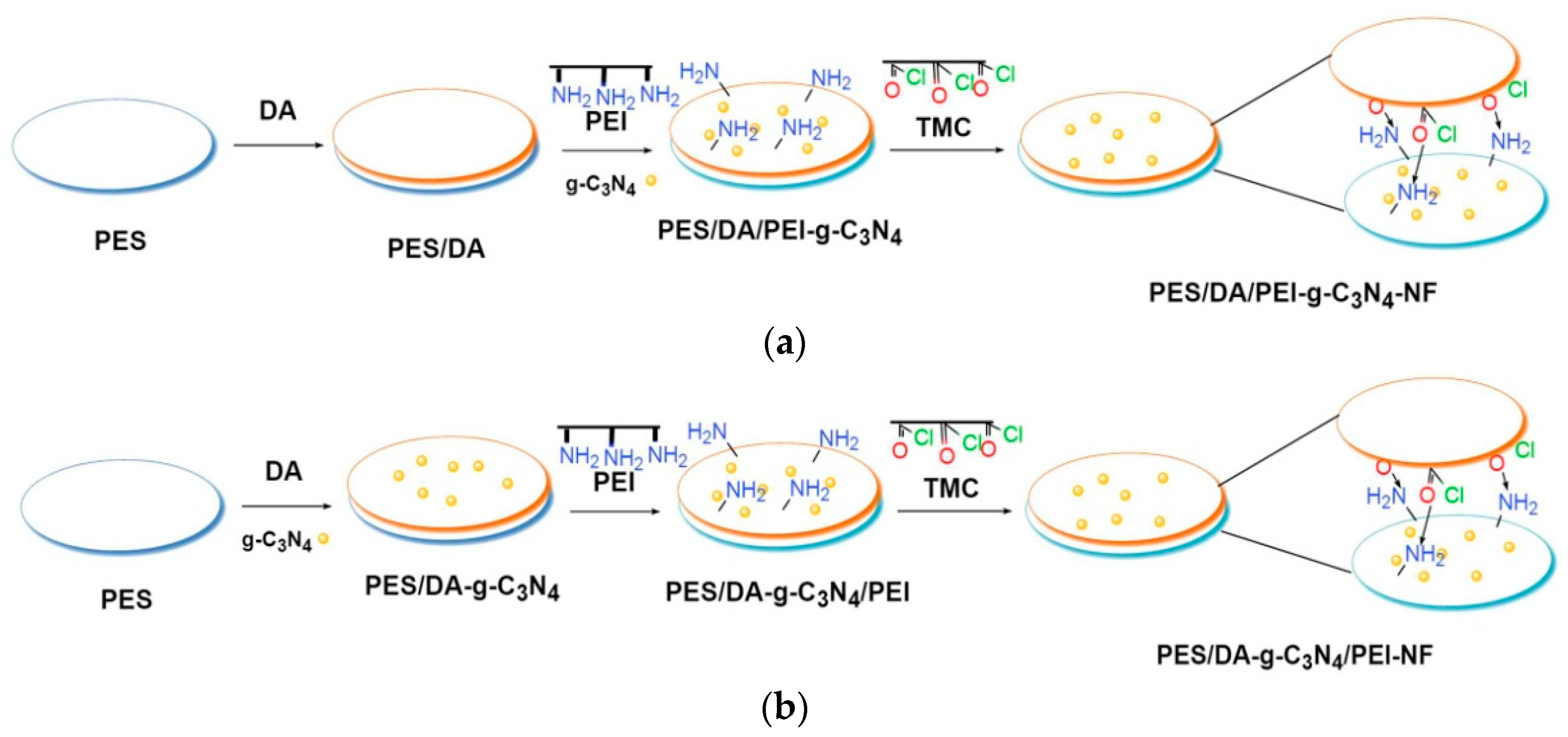
2.2.2. Preparation of NF Membrane

The schematic of the preparation of NF membranes is shown in Figure 1, and the preparation conditions are summarized in Table 1. First, PES UF membranes (M0) that were used as the base membranes for surface modification were soaked in ethanol for 2 h to remove air bubbles and impurities in and on the membranes, and then rinsed with pure water. After that, DA and g-C3N4-modified NF membranes were prepared as follows: (1) in Figure 1a, DA was immersed and then g-C3N4 was added to the PEI aqueous phase to prepare NF membrane (M4); and (2) in Figure 1b, g-C3N4 was dispersed in DA aqueous solution (2.0 g·L−1, pH = 8.5, DA hydrochloride in 50 mM·L−1 Tris buffer solution) using a probe sonicator (Biosafer 650-92, China) for 10 min to prepare DA-g-C3N4 aqueous solutions of different concentrations (0.01 wt%, 0.02 wt%, 0.03 wt%, and 0.04 wt%). PES membranes were immersed in DA-g-C3N4 aqueous solution at 25 °C for 2 h, and subsequently unreacted DA-g-C3N4 aqueous solution or low molecular weight PDA aggregates were removed to obtain PES membranes with PDA-g-C3N4 as the interlayer. Then, PEI aqueous solution (0.6 wt%) was poured on the interlayer for 2 min. Excess aqueous solution was removed, and then the membrane was covered with the TMC organic solution (0.1 wt%) in n-hexane for 2 min to allow the IP process to occur. Excess TMC was removed, and the membrane was cured at 70 °C for 15 min and then stored in pure water before use.

2.3. Characterization and Measurement

The chemical functional groups of g-C3N4 and the membrane surfaces were determined by Fourier transform infrared spectroscopy (FTIR, Thermo Fisher 6700 spectrometer, Waltham, MA, USA). The morphologies of inorganic materials (g-C3N4-96) were measured by transmission electron microscopy (TEM, a JEM-2100F, Tokyo, Japan). The element composition was determined by X-ray photoelectron spectroscopy (XPS, ESCALAB 250Xi, USA). The surface and cross-sectional morphologies of membranes were determined by scanning electron microscopy (SEM, SU8010, S4800, Japan). The surface zeta potential of membranes was characterized with a Sur-PASS electrokinetic analyzer (Anton Paar, Graz, Austria). Specifically, 1 mmol·L−1 KCl aqueous solution was used as the electrolyte, and 0.1 mol·L−1 HCl and 0.1 mol·L−1 KOH aqueous solution was used to control the pH value (3–10). The gap height of the measuring cell was fixed at 100 μm and the membranes were soaked in electrolyte for at least 4 h before the measurement. The water contact angle (WCA) was measured on a contact angle goniometer (JC2000D2, China) at room temperature with 1.5 μL of pure water droplet. The cation concentrations were measured using an atomic absorption spectrometer (A3F-13, China). The total organic carbon (TOC) was determined by a TOC-VCPN analyzer (Japan).

2.4. Permeance and Separation Performance of NF Membranes

The permeance and separation performance for mixed salt solutions (MgCl2·6H2O and LiCl, Mg2+/Li+ = 20, 48, 84, pH = 6.64, 6.59, 6.58) and the salt lake brine obtained from CITIC Guoan were tested using a lab-made cross-flow filtration system. The temperature of the feed tank jacket was kept at 20 ± 0.5 °C. Each membrane was pressurized with pure water at 0.4 MPa and 20 ± 0.5 °C for 0.5 h prior to testing to reach a steady state. The solution was replaced with 2.0 g·L−1 salt solutions or salt lake brine diluted 200 times and continuously fed for 0.5 h at 20 ± 0.5 °C and 0.4 MPa. The salt lake brine was diluted to the concentration of the mixed salt solution in order to compare with the results in the literature and reduce the osmotic pressure during the operation. The salt lake brine was used in this experiment to investigate the separation effect of NF membrane for complex solutions and fresh water was used for dilution. The composition of salt lake brine is very complex, and the pH and composition of the salt lake brine and diluted salt lake brine are shown in Table 2.
The proportion of strong acid–weak base salts or strong base–weak acid salts varies with the decrease or increase of neutral components, such as sodium chloride, sodium sulfate, and water, and the hydrolysis of these salts lowers or raises the pH of the salt lake brine [31]. The rejection rate (R, %), permeance (L·m−2·h−1·bar−1), and selectivity factor (SF) of Mg2+/Li+ were calculated by Equations (1)–(3), respectively. Cp (g·L−1) is the concentration of the permeation, Cf (g·L−1) is the concentration of the feed solution, V (L) is the volume of the permeation, A (m2) is the active surface area of the membrane, Δt (h) is the permeation time, Δp (bar) is the test pressure, CLi (g·L−1) and CMg (g·L−1) are the Li+ concentration and Mg2+ concentration in permeate and feed solutions.
R = ( 1 C p C f ) × 100 %
Permeance = V A × Δ t × Δ p
SF = ( C L i / C M g ) permeate ( C L i / C M g ) feed

2.5. Mean Pore Size and Pore Size Distribution

The molecular weight cut off (MWCO) and effective membrane pore size were determined via different molecular weights of 0.2 g⋅L−1 PEGs (200, 400, 600, 800, 1000, and 1500 Da) under 0.4 MPa and 20 ± 0.5 °C. The stokes diameter (d, nm) of PEG could be calculated according to its average molecular weight (Mw) by Equation (4). The pore size distribution of membranes was calculated by Equation (5) [31,32,33,34,35], where dp (nm) is the pore size in diameter, σp is the ratio of solute diameter at a rejection rate of 84.13%, and 50%, μp (nm) is the geometric mean diameter of the solute at a rejection rate of 50%.
d = 33.46 × 10 3 × M w 0.557
d F ( d p ) d d p = 1 d p l n σ p 2 π e x p [ ( l n d p l n μ p ) 2 2 ( l n σ p ) 2 ]

2.6. Antifouling Property of Membrane

The antifouling property was investigated in the cross-flow filtration module by BSA (IEP = 4.7, 0.1 g⋅L−1, pH = 6.95) and lysozyme (IEP = 10.7, 0.1 g⋅L−1, pH = 6.68) solution respectively. To reach a steady state, the membrane was pressurized with pure water at 0.4 MPa and 20 ± 0.5 °C for 1 h, and the volumetric permeate flux (Jv0) was measured every 20 min. The BSA solution was continuously fed for 2 h and the steady flux (Jv1) was measured every 20 min. After that, the tested membranes were washed with pure water at 0.1 MPa and 20 ± 0.5 °C for 20 min, and the permeate flux of pure water (Jv2) was measured again under the same operating conditions. After repeating the BSA antifouling test twice, the membranes were cleaned again, the BSA solution was replaced with a lysozyme solution and the same procedure was performed as described above. The steady flux (Jv, L·m−2·h−1), relative flux (RF), flux recovery ratio (FRR), total fouling ratio (FRt), reversible fouling ratio (FRr), and irreversible fouling ratio (FRir) were calculated by Equations (6)–(11), respectively:
J V = V A × Δ t
R F = J v 1 J v 0 × 100 %
F R R = J v 2 J v 0 × 100 %
F R t = ( 1 J v 1 J v 0 ) × 100 %
F R r = ( J v 2 J v 1 J v 0 ) × 100 %
F R i r = ( 1 J v 2 J v 0 ) × 100 %

3. Results and Discussion

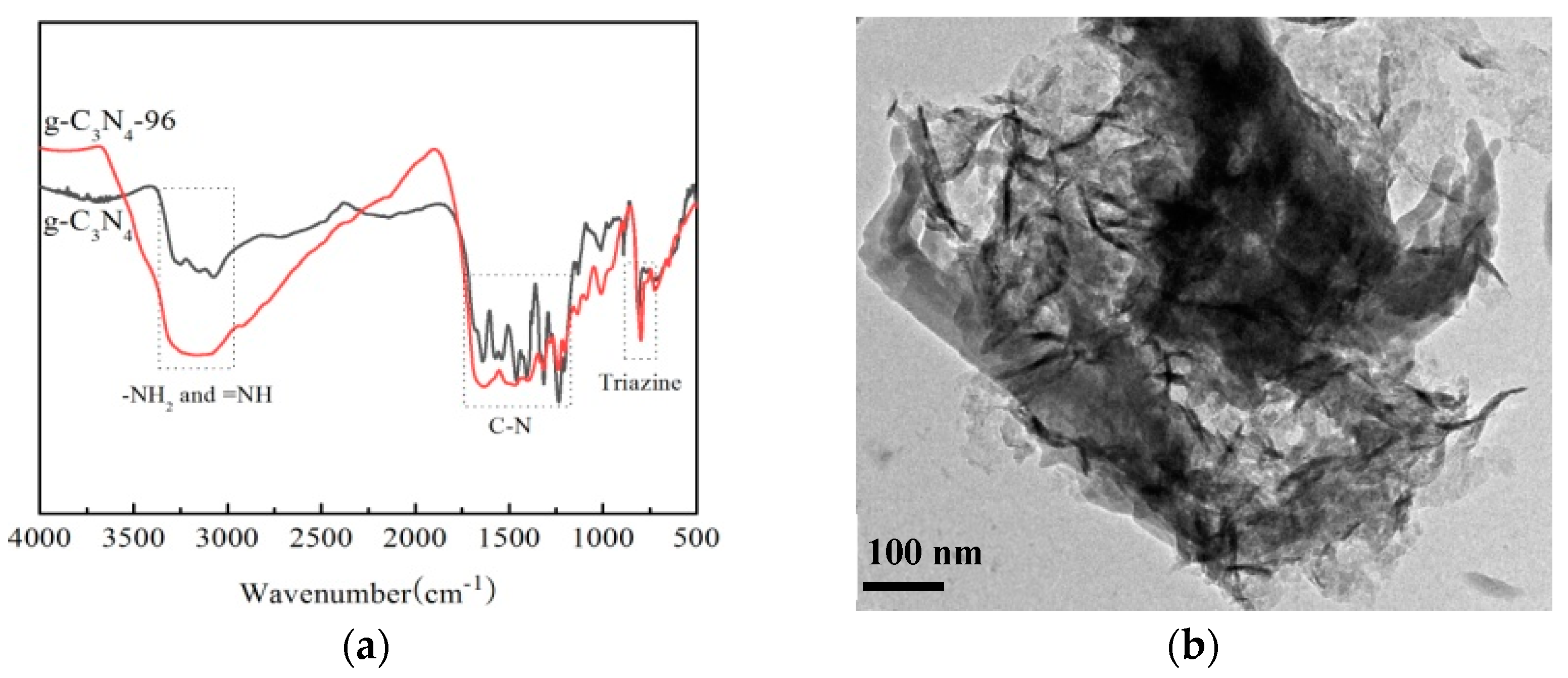
3.1. Characterization of g-C3N4-96

The FTIR spectra of g-C3N4-96 are shown in Figure 2a. In the spectrum of g-C3N4, the absorption peak at 802 cm−1 corresponds to the characteristic breathing mode of triazine units, while those peaks in the range of 1234–1637 cm−1 are assigned to the stretching vibration of C-N and C=N heterocycles, which are similar to those reported in previous studies [36,37]. The broad peak in the range of 3000–3500 cm−1 is owed to the stretching vibrations of N-H or N-H2 originated from uncondensed amino groups [38]. In Figure 2b, a typical ultrathin nanosheets-like architecture with a crinkly structure is observed for g-C3N4-96. This is because urea-inorganic ammonium salts were used as additives, and gas was continuously released during the polymerization of melamine to form g-C3N4 nanosheets.

3.2. Characterization of Membrane

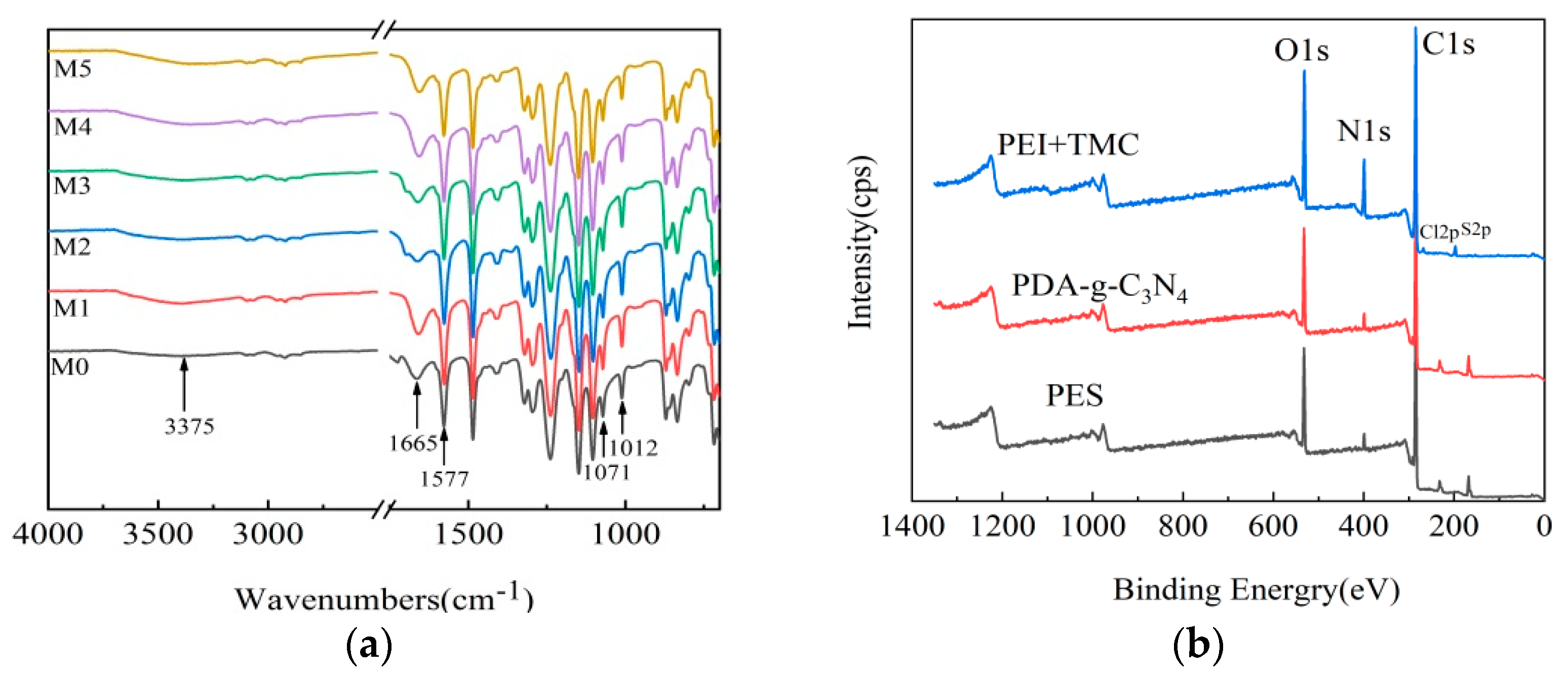
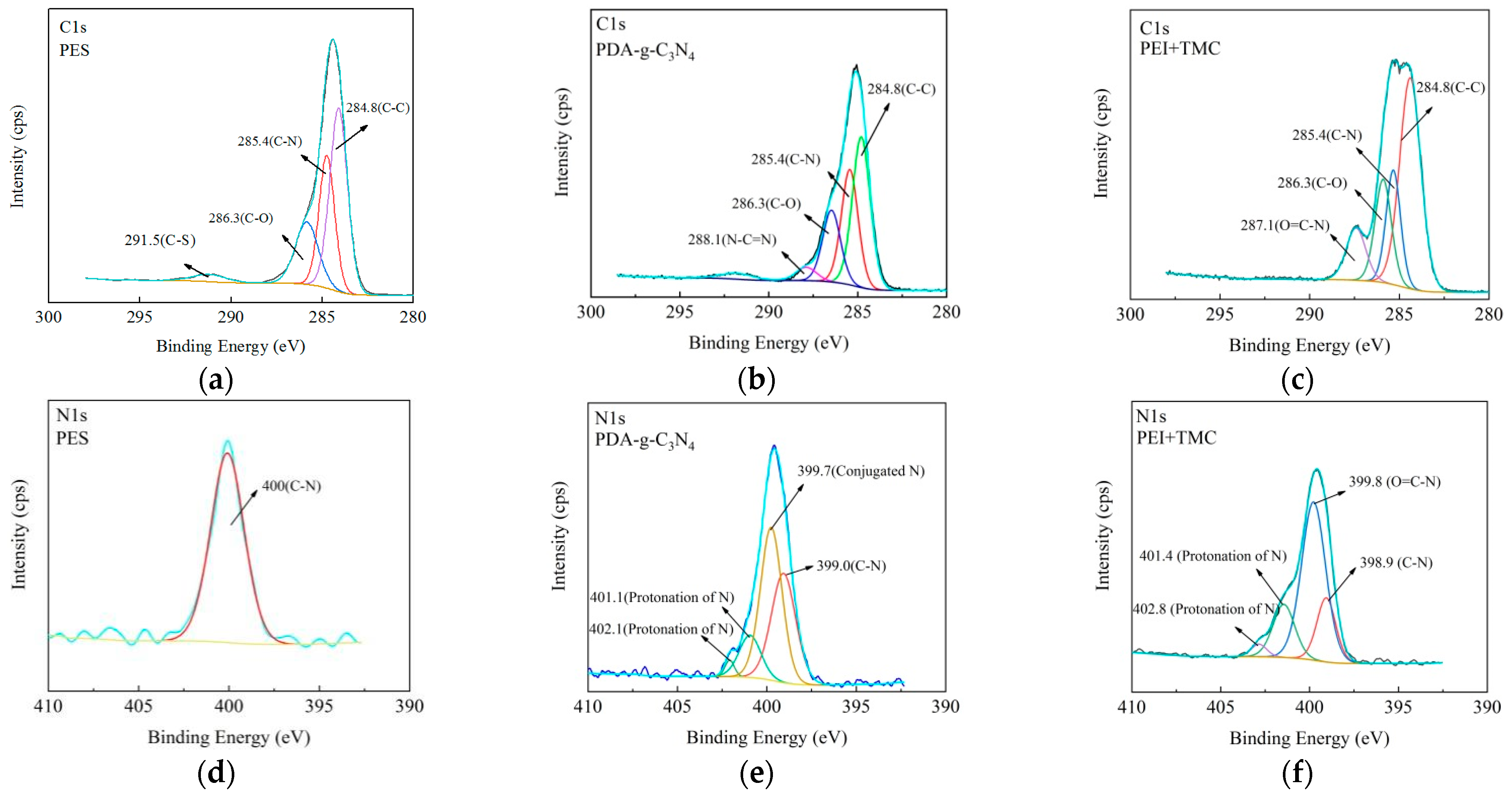
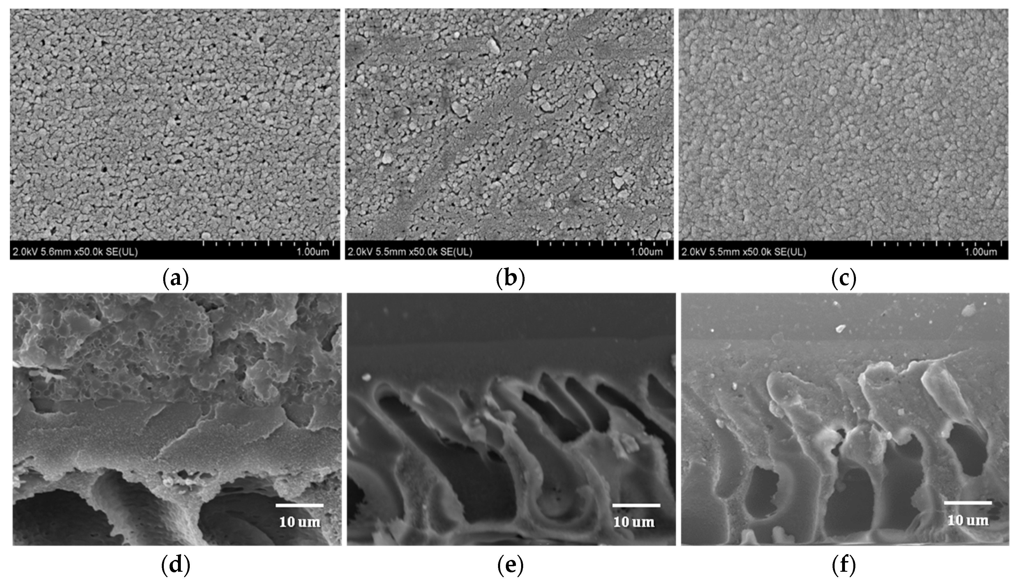
3.2.1. Chemical Structure and Morphology

The chemical structures of the surface of M0, M1, M2, M3, M4, and M5 membranes were determined by FTIR (Figure 3a). There are several peaks in M1, M2, M3, M4, and M5 membranes: O-H and uncondensed terminal amino groups (3375 cm−1), amide I, C=O band (1665 cm−1), amide II and C-N stretching from IP (1577 cm−1), and the stretching vibration of -COO (1071 and 1012cm−1) originated from the hydrolysis of -COCl in TMC [39]. However, the vibration strength of M1, M2, M3, M4, and M5 membranes at 1665 and 1577 cm−1 is higher than that of M0 membrane. These results indicate that IP reaction occurred on the surface of the NF membrane. The element composition and contents in different layers of the M5 membrane were determined by in situ XPS (Figure 3b). Three main emission peaks are observed, which are ascribed to O1s (531 eV), N1s (399 eV) and C1s (285 eV), respectively. There are two small peaks at 232 eV (Cl2p) and168 eV (S2p) in the PES UF membrane (PES layer), and the Cl content is negligible. The C content is higher, but the N content is lower on the PES layer (Table 3). Compared to the PES layer, the contents of N and O elements are higher in the PDA-g-C3N4 interlayer, which is due to the high N content in PDA and g-C3N4 [40], and the N content is increased from 2.96% to 6.95%. The N content in the PEI + TMC layer is increased to 11.08%, which is mainly derived from N-C=O and NH2 (NHR) groups. The amide groups are attributed to the introduction of O=C-N groups by IP of PEI and TMC, and a dense PA layer is formed on the surfaces of membranes. The primary and secondary amines are derived from unreacted PEI. Thus, the cross-linking degree of the NF membrane can be assessed by the percentage of amide groups.
The in situ high resolution C1s and N1s XPS spectra of M5 membrane are deconvoluted and fitted to analyze the surface chemical properties (Figure 4). The C1s XPS spectrum of PES layer is deconvoluted into four peaks (Figure 4a), which are attributed to the C-C bond (284.8 eV), the C-N (285.4 eV) bond derived from the preparation of PES, the C-O bond (286.3 eV), and the C-S bond (291.5 eV) of PES, respectively [41]. The PDA-g-C3N4 layer shows four peaks corresponding to C-C (284.8 eV), C-N (285.8 eV), C-O (286.3 eV), and N-C=N (288.0eV) (Figure 4b). The N-C=N bond is attributed to C sp2 hybridization that represents the unique tri-s-triazine rings of g-C3N4 [20]. For the PEI + TMC layer, four peaks are observed at 287.1 (O=C-N), 286.3 (C-O), 285.8 (C-N), and 284.8 (C-C) eV (Figure 4c). The peak of O=C-N (287.1 eV) indicates that IP reaction has occurred [42]. The high-resolution N1s spectra are shown in Figure 4d–f. There is only one peak at 400 eV (C-N) for the PES layer, which corresponds to C-N introduced during the preparation of PES membrane. Several new peaks are observed in PDA-g-C3N4 and PEI + TMC layers. For the PDA-g-C3N4 layer, the peaks at 402.4, 401.2, 399.7 and 390.0 eV correspond to protonated N, conjugated N and C-N bonds, respectively, while for the PEI + TMC layer, the peaks at 402.8, 401.4, 399.8, and 389.9 eV correspond to the protonated N, conjugated N, O=C-N bond, and C-N bond of amides, respectively [43].
The surface and cross-sectional SEM images of the PES, PES/PDA-g-C3N4 interlayer, and M5 membranes are shown in Figure 5. The porous surface of PES UF membrane (Figure 5a) disappears after the co-deposition of PDA and g-C3N4 and instead a dense layer is formed with PDA aggregation (Figure 5b). The surface of M5 membrane is denser and smoother after the IP of PEI and TMC (Figure 5c). On the other hand, the PES membrane has an asymmetric morphology with micro-porous finger-like and spongy-like structures (Figure 5d). A clearly visible thin selective layer is formed on the surface of PES membrane (Figure 5e,f), which is considered to be the interlayer formed by the co-deposition of PDA-g-C3N4 and the active separation layer formed after IP reaction.

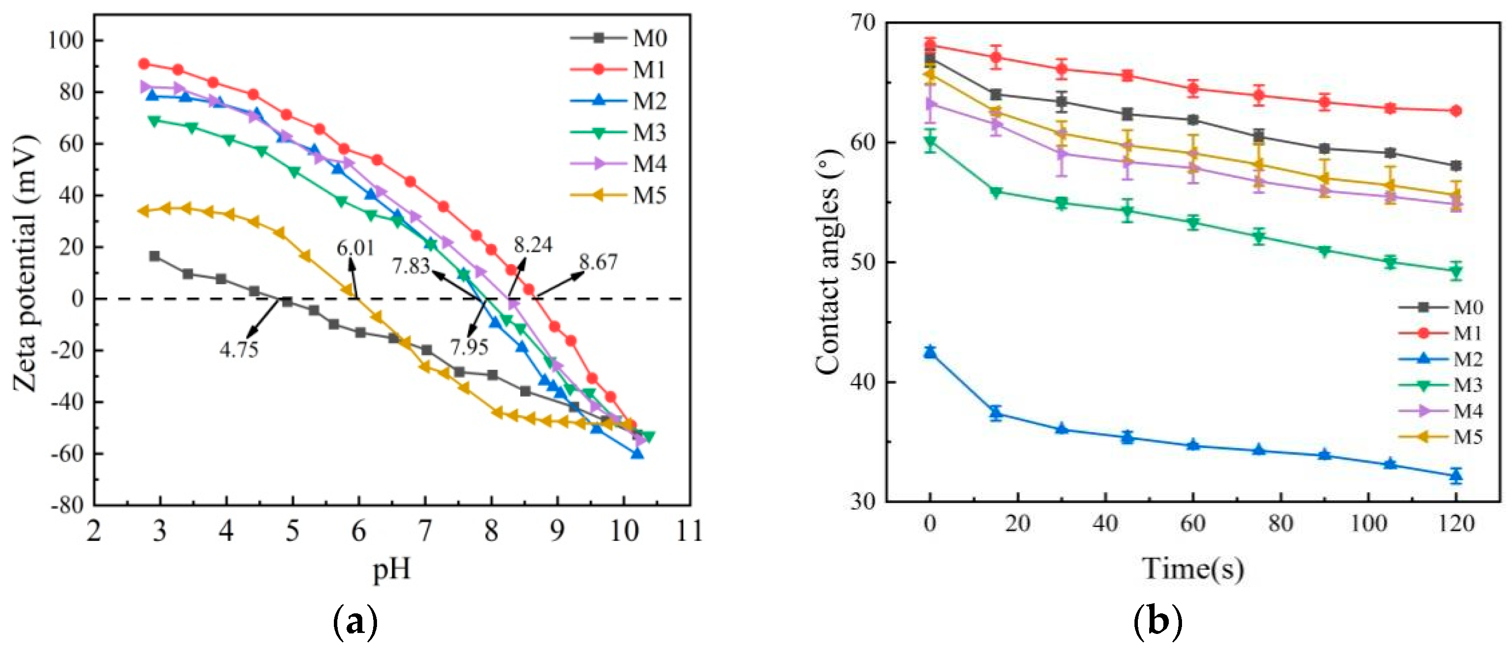
3.2.2. Zeta Potential and Hydrophilicity of Membranes

As shown in Figure 6a, the isoelectric point (IEP) of M0 is 4.75, indicating that the PES membrane is negatively charged at pH > 4.75. The IEPs of M1, M2, M3, M4, and M5 membranes (6.01, 7.83, 7.95, 8.24, and 8.67, respectively) are much higher compared to M0 membrane, owing to a large number of positive unreacted primary and secondary amine groups (-NH3+ and -NH2+) from PEI [44]. M1, M2, M3, M4, and M5 membranes are positively charged at pH < 6.01. The IEPs of M3, M4, and M5 membranes are lower than that of the M1 membrane, which is attributed to the presence of abundant -OH and C-O on the PDA layer. Although the IEP of M5 membrane is only 6.01, its relative SF is the highest because of the effects of hydrophilicity and pore size on separation performance. NF membranes generally operate at a pH of about 6.0 [45], and theM5 membrane is positively charged during NF operation. The WCA was measured to analyze the hydrophilicity of membrane surfaces (Figure 6b). The WCAs follow the order of M1 > M0 > M5 > M4 > M3 > M2. It should be noted that the WCAs of the M1 membrane are always higher than that of other membranes, indicating that the PA NF membrane is less hydrophilic. The g-C3N4 in the PEI aqueous phase forms hydrogen bonds with water molecules, which enhances the affinity of water molecules with the membrane surface and reduces the WCAs of M2 membrane [22]. The hydrophilicity can be improved by adding g-C3N4 or depositing DA on the surface of the base membrane. The WCAs of the M5 membrane decrease because of the formation of the PDA-g-C3N4 interlayer.

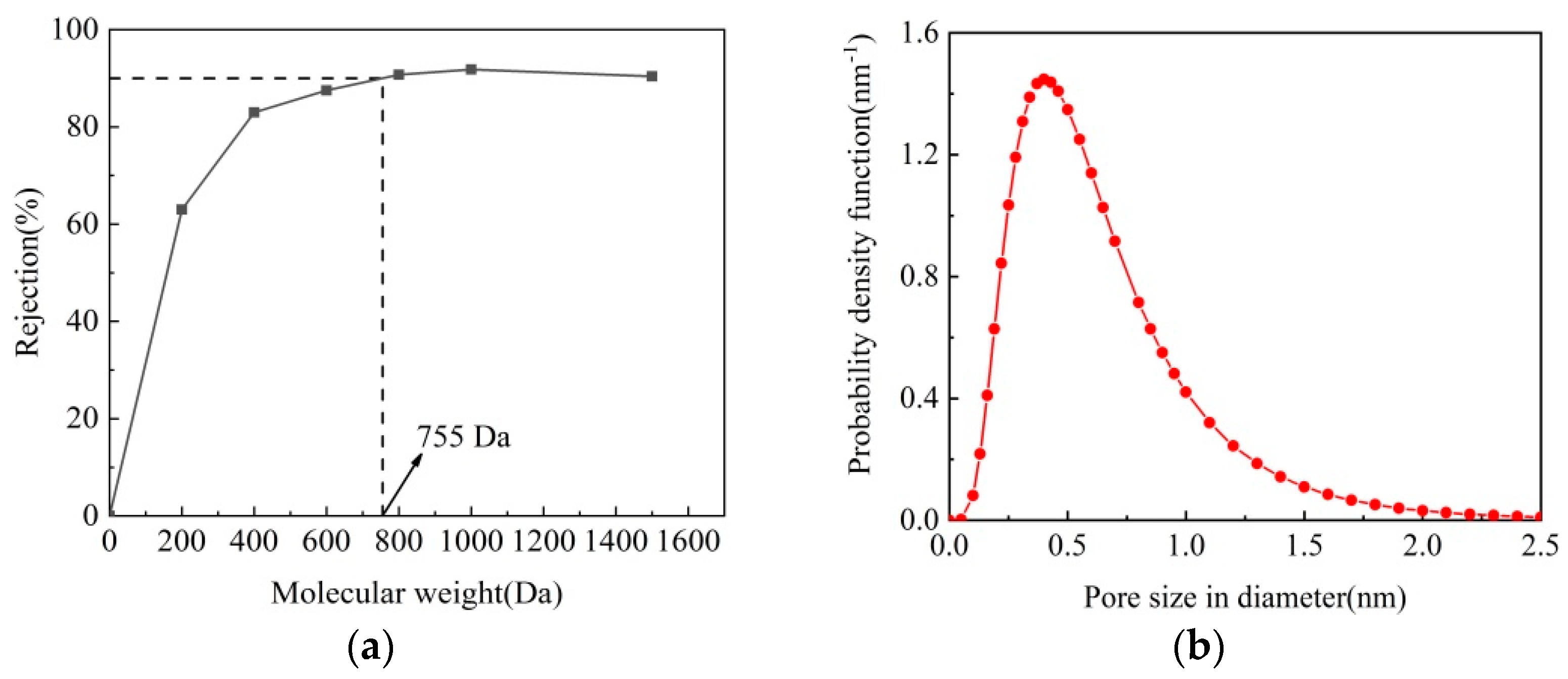
3.2.3. MWCO and Pore Size Distribution of M5 Membrane

The MWCO can be used to evaluate the pore size of the NF membranes, which is obtained by the Mw as the rejection of neutral solutes reaches 90%. Figure 7 shows the rejection of M5 membrane to neutral solutes (PEG 200, 400, 600, 800, 1000, and 1500 Da). The MWCO of M5 membrane is about 755 Da, and the pore radius is about 0.41 nm. It is known that the MWCO value of NF membranes are in the range of 200–1000 Da. It can be concluded that M5 membrane fabricated in this study is a NF membrane, and a dense NF active layer is formed on the surface of M5 membrane.

3.3. Separation Performance and Antifouling Property

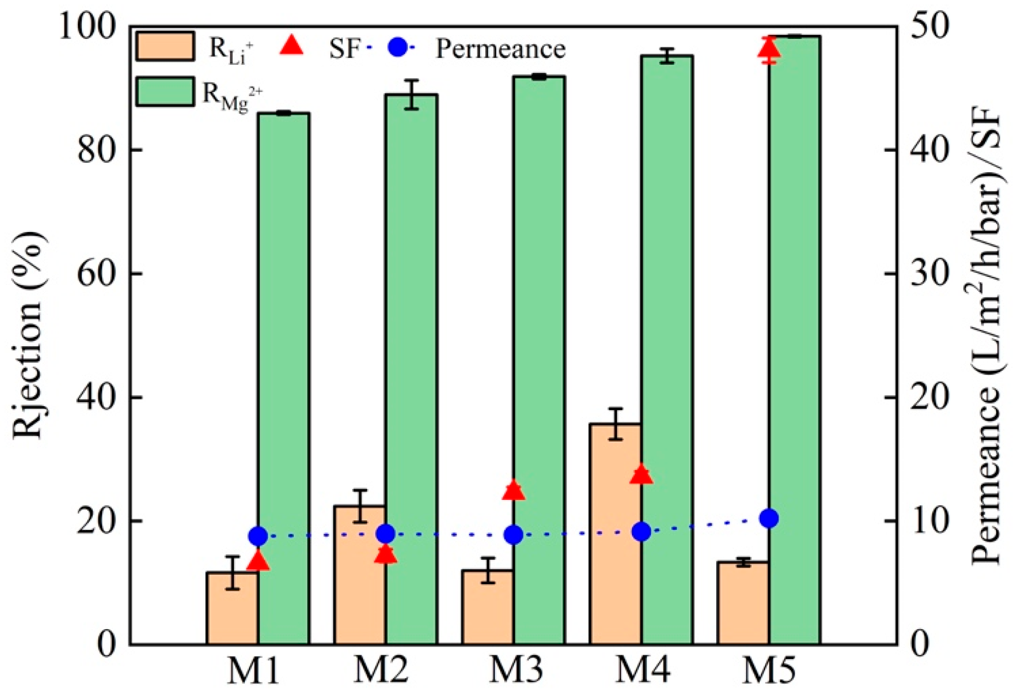
3.3.1. Effects of Preparation Conditions on NF Membrane Performance

Figure 8a,b shows the effects of PEI concentration and immersion time on the SF and permeance of NF membranes. As the PEI concentration increases from 0.2 to 0.8 wt%, the permeance increases, the SF first increases and then decreases. The IP process is slower at lower PEI concentration, leading to a loose PA selective layer with lower selective separation performance. The IP rate increases with increasing PEI concentration, forming a denser PA selective layer. However, the continuous increase of PEI concentration would enhance the permeance and reduce the selective separation performance. This is because at high PEI concentrations, there is a limited supply of TMC and a large number of unreacted amine groups are left in the PA active layer, which would reduce the degree of cross-linking [45]. Thus, the optimal PEI concentration is determined to be 0.6 wt%. Increasing the immersion time leads to no significant improvement of the separation performance but a reduction in the permeance. Thus, the optimal immersion time is determined to be 2 min. As shown in Figure 8c,d, as the concentration of TMC in n-hexane increases from 0.05 to 0.4 wt%, the separation performance first increases and then decreases, while the permeance gradually decreases. This is because there is no sufficient TMC to react with PEI at low TMC concentrations and the IP is weak. However, once the optimum IP is achieved, the increasing of the TMC concentration would actually decrease the separation performance, because the hydrolysis of unreacted acid chloride groups in TMC to carboxyl groups reduces the degree of IP between PEI and TMC. Considering that the IP reaction time is short, increasing the time will not help to increase the permeance. Thus, the TMC concentration of 0.1 wt% and the reaction time of 2 min are considered to be the best choice. The effects of g-C3N4 concentration and the immersion time of DA are shown in Figure 8e,f, respectively. Adding g-C3N4 could increase the permeance of the membrane, but too high g-C3N4 content would reduce the separation performance. Thus, the optimum amount of g-C3N4 is determined to be 0.02 wt%. Once the immersion time exceeds 2 h, increasing the immersion time will not increase the separation performance but will significantly reduce the permeance. Therefore, 2 h is selected as the most appropriate immersion time, which is shorter than that reported in the previous literature [23,24]. Figure 9 shows the effect of stripping time of g-C3N4 (24 h, 48 h, 96 h, and 192 h) on the separation performance and permeance. It an be seen that the membrane fabricated for 96 h has the best separation performance and permeance.
The Mg2+ rejection, Li+ rejection, SF and the permeance of M1, M2, M3, M4, and M5 membranes in 2.0 g·L−1 LiCl and MgCl2 mixed solution (Mg2+/Li+ = 20) are compared (Figure 10). For M4 membrane, the rejection is 94.61% for Mg2+ and 27.82% for Li+, the SF is 13.39, and the permeance is 9.14 L·m−2·h−1·bar−1. M5 membrane exhibits a permeance up to 10.19 L·m−2·h−1·bar−1 and a SF up to 48.08, the rejection is high (98.20%) for Mg2+ but low (13.33%) for Li+, and the Mg2+/Li+ ratio of the permeate is 0.036. As shown in Figure 1, for M4 membrane, g-C3N4 is an additive to the PEI solution and a PA layer is from the the IP reaction with IMC, while for M5 membranes, g-C3N4 is co-deposited with DA as the interlayer. It is seen that the separation performance of M4 membrane is not much improved compared to M3 membrane (deposited PDA, no g-C3N4), which indicates that the presence of g-C3N4 in the IP layer has no significant effect on the membrane properties. The fabrication of a defect-free intermediate layer with an appropriate thickness is an important step for the preparation of multilayer composite membranes with high-permeability [46,47]. The better performance of M5 membrane could be attributed to the use of PDA-g-C3N4 as the interlayer material to avoid pore penetration of the selective layer. The addition of g-C3N4 nanosheets can form a thin and defect-free interlayer with PDA and completely cover the surface of the PES substrate [48]. Thus, the positively charged NF membrane prepared with PDA-g-C3N4 as the interlayer has better separation performance and permeance.

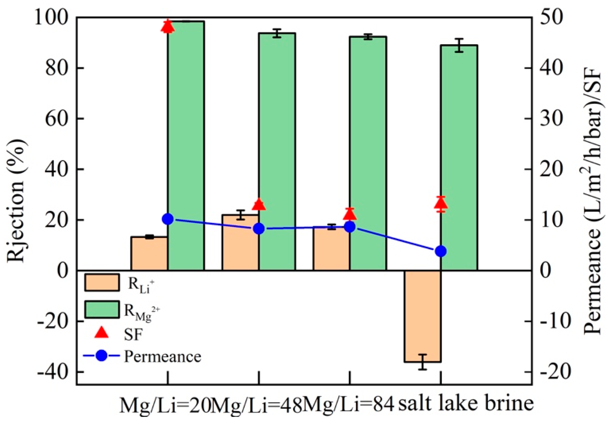
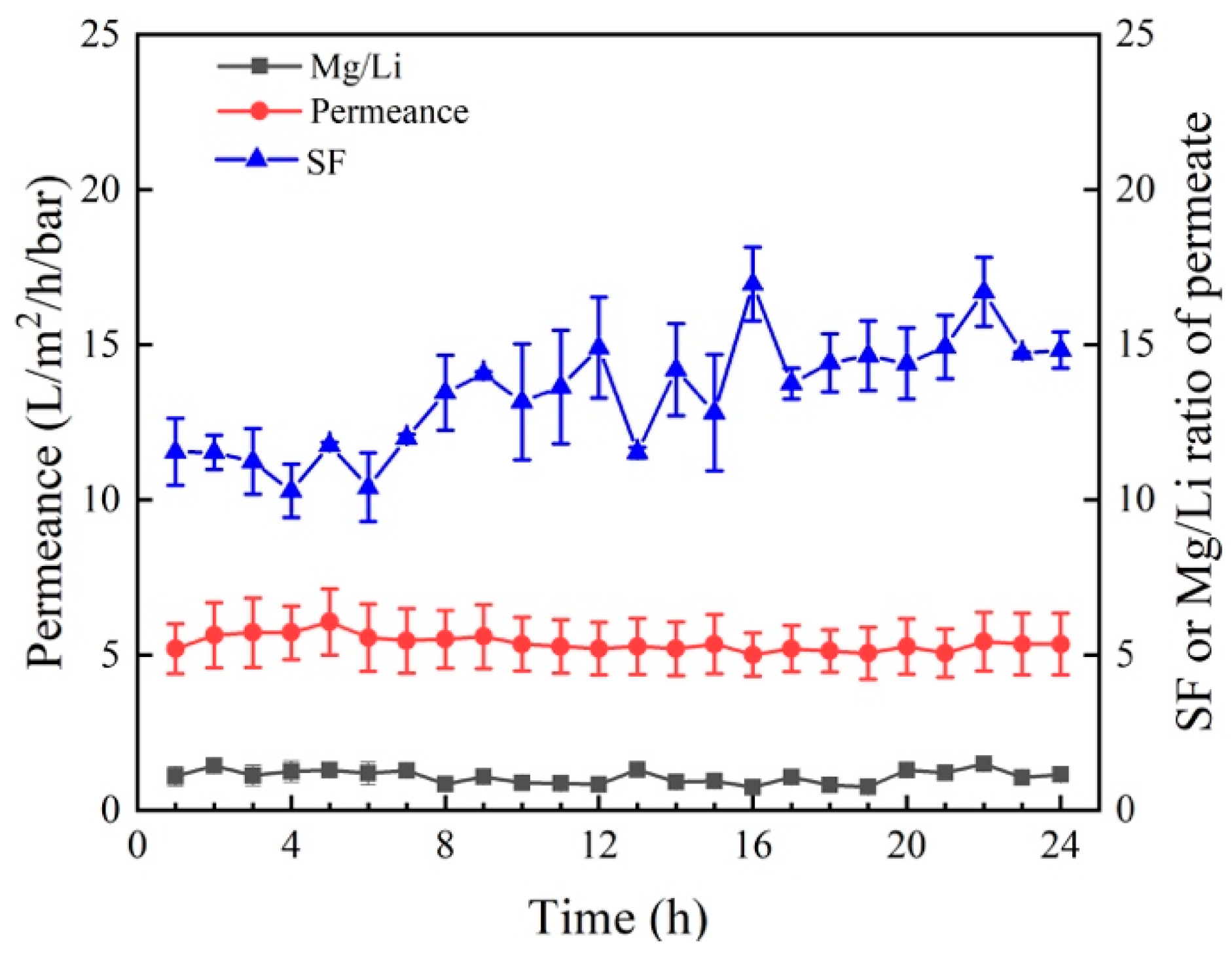
3.3.2. Separation Performance and Permeance of M5 in Different Solutions

Based on the excellent separation ability of Mg2+ and Li+ in the salt solution with a Mg2+/Li+ ratio of 20, the separation performance and permeance of M5 membrane in salt solutions with a Mg2+/Li+ ratio of 48 and 81 are examined. It is found that at a Mg2+/Li+ ratio of 48, the SF of M5 membrane is 15.14 and the permeance is 8.60 L·m−2·h−1·bar−1; while at a Mg2+/Li+ ratio of 84, the SF is 10.77 and the permeance is 7.51 L·m−2·h−1·bar−1 (Figure 11). The SF of the M5 membrane decreases with the increase of the Mg2+/Li+ ratio, but the rejection of Mg2+ is always higher than 92.36%. In order to further investigate the separation performance of M5 membrane for Mg2+ and Li+ in complex solutions, the salt lake brine collected from CITIC Guoan was used in the separation experiments. The rejection of Mg2+ of M5 membrane is dropped to 88.94%, and the Mg2+/Li+ ratio of the permeate is 1.43, which may be related to the complex composition of salt lake brine. There may be other monovalent (e.g., Na+ and K+) and divalent cations, in addition to Mg2+ and Li+. In spite of this, the M5 membrane still exhibits an excellent separation of Mg2+ and Li+ (SF = 12.79).
Table 4 compares the separation performance of several reported NF membranes and M5 membranes prepared in this work. It was found that the rejection of Mg2+ differs substantially among NF membranes. Importantly, the M5 membrane shows higher Mg2+ rejection and permeance than other NF membranes. According to Figure 12, the permeance (5.01–6.06), Mg2+/Li+ ratio of the permeate (0.73–1.43), and SF (10.28–16.69) change little during the longtime filtration test. As a result, the M5 membrane has high stability during the filtration process.

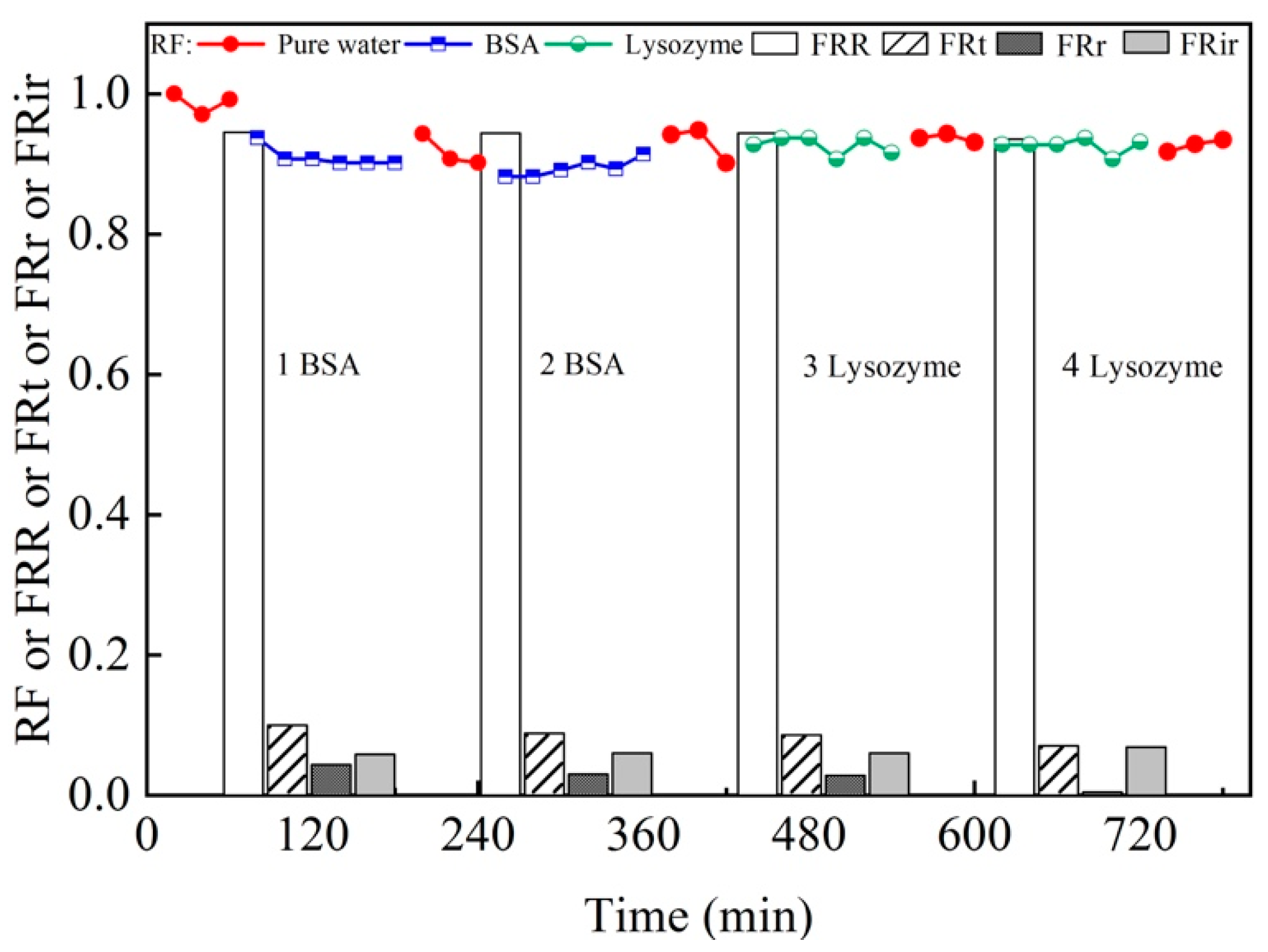
3.3.3. Antifouling Property of the M5 Membrane

The variations of water flux with time and the antifouling property of M5 membrane during the cyclic filtration for BSA and lysozyme solutions are shown in Figure 13. The permeate flux is lower than the water flux and maintained at a steady state in each circle, indicating that the adsorption/deposition and back diffusion of BSA and lysozyme reaches an equilibrium [52]. However, it could not be fully recovered because membrane pores could be blocked by contaminants [53]. In general, the higher the hydrophilicity of the membrane is, the greater the resistance to fouling adsorption will be. This is due to the formation of hydrogen bonds with water molecules on the hydrophilic surface and the formation of a hydrated layer on the membrane surface that can prevent organic contaminants from being absorbed into the membrane matrix [54]. A higher FRR indicates superior antifouling performance of membranes. The values of FRR, FRt, FRr, and FRir change slightly with the increasing filtration cycle, indicating that the M5 membrane has an excellent antifouling property for BSA and lysozyme. As a result, the M5 membrane can efficiently reduce membrane fouling and exhibit good stability during the cyclic BSA and lysozyme filtration.

4. Conclusions

A positively charged NF membrane with a sandwich structure was successfully fabricated by depositing PDA-g-C3N4 as the interlayer on the surface of PES membrane, followed by the IP process of PEI and TMC on the interlayer. The concentrations of PEI (0.6 wt%), TMC (0.1 wt%), g-C3N4 (0.02 wt%, stripping 96 h), and interlayer reaction time (2 h) are optimized. The final NF membrane (M5) has a low WCA (55.5°) and the IEP is 6.01, which is attributed to the hydrophilic, positively charged active separation layer on the NF membrane surface resulting from the IP process of PEI and TMC. Notably, the permeance of the M5 membrane is up to 10.19 L·m−2·h−1·bar−1 and the rejection of Mg2+ is 98.2%. This is because the use of PDA-g-C3N4 as the interlayer is conducive to the penetration and diffusion of water molecules on the membrane surface. The high permeance will not affect the salt rejection rate, which is mainly due to the pore size of the NF membrane and the strong electrostatic repulsion between the abundant positive charges and the polyvalent cations on the membrane surface. The M5 membrane also has good and stable separation performance for complex salt lake brine and antifouling property. To conclude, the as-prepared positively charged NF membrane has the potential to be used for recovering Li+ from brine due to its ready availability, high efficiency, and good adaptability.

Author Contributions

Conceptualization, Q.B.; Data curation, L.M., F.Q., H.Z. and Y.G.; Formal analysis, L.M., F.Q., H.Z. and Y.G.; Funding acquisition, Q.B. and S.X.; Investigation, L.M.; Methodology, L.M., C.Z. and S.X.; Resources, S.X.; Supervision, Y.T., C.Z. and S.X.; Writing—original draft, L.M.; Writing—review & editing, Q.B., Y.T. and S.X. All authors have read and agreed to the published version of the manuscript.

Funding

This research was funded by the National Natural Science Foundation of China (U20A20139), the Foundation from Qinghai Science and Technology Department (2020-HZ-808, 2021-ZJ-939Q), Thousand Talents Program of Qinghai Province, Scientific Research Fund of Young Teachers in Qinghai University (2020-QGY-6, 2022-QGY-7), and the Innovation and Entrepreneurship Program of Qinghai University (2021-QX-23).

Acknowledgments

This research is financially supported by the National Natural Science Foundation of China (U20A20139), the Foundation from Qinghai Science and Technology Department (2020-HZ-808, 2021-ZJ-939Q), Thousand Talents Program of Qinghai Province, Scientific Research Fund of Young Teachers in Qinghai University (2020-QGY-6, 2022-QGY-7), and the Innovation and Entrepreneurship Program of Qinghai University (2021-QX-23).

Conflicts of Interest

The authors declare no conflict of interest.

References

  1. Xu, S.S.; Song, J.F.; Bi, Q.Y.; Chen, Q.; Zhang, W.M.; Qian, Z.X.; Zhang, L.; Xu, S.A.; Tang, N.; He, T. Extraction of lithium from Chinese salt-lake brines by membranes: Design and practice. J. Membr. Sci. 2021, 635, 119441. [Google Scholar] [CrossRef]
  2. Li, N.; Guo, C.S.; Shi, H.T.; Xu, Z.W.; Xu, P.; Teng, K.Y.; Shan, M.J.; Qian, X.M. Analysis of Mg2+/Li+ separation mechanism by charged nanofiltration membranes: Visual simulation. Nanotechnology 2021, 32, 085703. [Google Scholar] [CrossRef]
  3. Zhang, C.Y.; Mu, Y.X.; Zhao, S.; Zhang, W.; Wang, Y.X. Lithium extraction from synthetic brine with high Mg2+/Li+ ratio using the polymer inclusion membrane. Desalination 2020, 496, 114710. [Google Scholar] [CrossRef]
  4. Swain, B. Recovery and recycling of lithium: A review. Sep. Purif. Technol. 2017, 172, 388–403. [Google Scholar] [CrossRef]
  5. Liu, G.; Zhao, Z.W.; He, L.H. Highly selective lithium recovery from high Mg/Li ratio brines. Desalination 2020, 474, 114185. [Google Scholar] [CrossRef]
  6. Sun, Y.; Wang, Q.; Wang, Y.H.; Yun, R.P.; Xu, X. Recent advances in magnesium / lithium separation and lithium extraction technologies from salt lake brine. Sep. Purif. Technol. 2021, 256, 117807. [Google Scholar] [CrossRef]
  7. Tabelin, C.B.; Dallas, J.; Casanova, S.; Pelech, T.; Bournival, G.; Saydam, S.; Canbulat, I. Towards a low-carbon society: A review of lithium resource availability, challenges and innovations in mining, extraction and recycling, and future perspectives. Miner. Eng. 2021, 163, 106743. [Google Scholar] [CrossRef]
  8. Shao, W.Y.; Liu, C.R.; Yu, T.; Xiong, Y.; Hong, Z.; Xie, Q.L. Constructing Positively Charged Thin-Film Nanocomposite Nanofiltration Membranes with Enhanced Performance. Polymers 2020, 12, 2526. [Google Scholar] [CrossRef] [PubMed]
  9. Zhang, Y.; Wang, L.; Sun, W.; Hua, Y.H.; Tang, H.H. Review Membrane technologies for Li+/Mg2+ separation from salt-lake brines and seawater: A comprehensive review. J. Ind. Eng. Chem. 2020, 81, 7–23. [Google Scholar] [CrossRef]
  10. Saif, H.M.; Huertas, R.M.; Pawlowski, S.; Crespo, J.G.; Velizarov, S. Development of highly selective composite polymeric membranes for Li+/Mg2+ separation. J. Membr. Sci. 2021, 620, 118891. [Google Scholar] [CrossRef]
  11. Wu, H.H.; Lin, Y.K.; Feng, W.Y.; Liu, T.Y.; Wang, L.; Yao, H.; Wang, X.L. A novel nanofiltration membrane with [MimAP][Tf2N] ionic liquid for utilization of lithium from brines with high Mg2+/Li+ ratio. J. Membr. Sci. 2020, 603, 117997. [Google Scholar] [CrossRef]
  12. Somrani, A.; Hamzaoui, A.H.; Pontie, M. Study on lithium separation from salt lake brines by nanofiltration (NF) and low pressure reverse osmosis (LPRO). Desalination 2013, 317, 184–192. [Google Scholar] [CrossRef]
  13. Sun, S.Y.; Cai, L.J.; Nie, X.Y.; Song, X.; Yu, J.G. Separation of magnesium and lithium from brine using a Desal nanofiltration membrane. J. Water Process Eng. 2015, 7, 210–217. [Google Scholar] [CrossRef]
  14. Akamatsu, K.; Igarashi, Y.; Marutani, T.; Shintani, T.; Nakao, S. Development of Novel Positively Charged Nanoltration Membranes Using Interfacial Polymerization, Followed by Plasma Graft Polymerization. J. Chem. Eng. Jpn. 2021, 54, 28–34. [Google Scholar] [CrossRef]
  15. Wang, Z.; You, X.D.; Yang, C.; Li, W.W.; Li, Y.F.; Li, Y.; Shen, J.L.; Zhang, R.N.; Su, Y.L.; Jiang, Z.Y. Ultrathin polyamide nanofiltration membranes with tunable chargeability for multivalent cation removal. J. Membr. Sci. 2022, 642, 119971. [Google Scholar] [CrossRef]
  16. Wang, L.; Lin, Y.K.; Tang, Y.H.; Ren, D.; Wang, X.L. Fabrication of oppositely charged thin-film composite polyamide membranes with tunable nanofiltration performance by using a piperazine derivative. J. Membr. Sci. 2021, 634, 119405. [Google Scholar] [CrossRef]
  17. Gohil, J.M.; Ray, P. A review on semi-aromatic polyamide TFC membranes prepared by interfacial polymerization: Potential for water treatment and desalination. Sep. Purif. Technol. 2017, 181, 159–182. [Google Scholar] [CrossRef]
  18. Petersen, R.J. Composite reverse-osmosis and nanofiltration membranes. J. Membr. Sci. 1993, 83, 81–150. [Google Scholar] [CrossRef]
  19. Jiang, Z.B.; Miao, J.; He, Y.T.; Tu, K.; Chen, S.Q.; Zhang, R.; Zhang, L.; Yang, H. A novel positively charged composite nanofiltration membrane based on polyethyleneimine with a tunable active layer structure developed via interfacial polymerization. RSC Adv. 2019, 9, 10796–10806. [Google Scholar] [CrossRef] [Green Version]
  20. Ge, M.N.; Wang, X.Y.; Wu, S.Y.; Long, Y.L.; Yang, Y.; Zhang, J.F. Highly antifouling and chlorine resistance polyamide reverse osmosis membranes with g-C3N4 nanosheets as nanofiller. Sep. Purif. Technol. 2021, 258, 117980. [Google Scholar] [CrossRef]
  21. Lu, Y.; Sun, D.S.; Lu, Y.; Yan, Y.S.; Hu, B. Zwitterion imprinted composite membranes with obvious antifouling character for selective separation of Li ions. Korean J. Chem. Eng. 2020, 37, 707–715. [Google Scholar] [CrossRef]
  22. Shahabi, S.S.; Azizi, N.; Vatanpour, V. Synthesis and characterization of novel g-C3N4 modified thin film nanocomposite reverse osmosis membranes to enhance desalination performance and fouling resistance. Sep. Purif. Technol. 2019, 215, 430–440. [Google Scholar] [CrossRef]
  23. Mi, Z.M.; Liu, Z.X.; Jin, S.Z.; Zhang, D.W.; Wang, D.M. Positively charged nanofiltration membrane prepared by polydopamine deposition followed by crosslinking for high efficiency cation separation. Polym. Test. 2021, 93, 107000. [Google Scholar] [CrossRef]
  24. Li, F.; Yu, Z.X.; Shi, H.; Yang, Q.B.; Chen, Q.; Pan, Y.; Zeng, G.Y.; Yan, L. A Mussel-inspired method to fabricate reduced graphene oxide/g-C3N4 composites membranes for catalytic decomposition and oil-in-water emulsion separation. Chem. Eng. J. 2017, 322, 33–45. [Google Scholar] [CrossRef]
  25. Ghalamchi, L.; Aber, S.; Vatanpour, V.; Kian, M. Comparison of NLDH and g-C3N4 nanoplates and formative Ag3PO4 nanoparticles in PES microfiltration membrane fouling: Applications in MBR. Chem. Eng. Res. Des. 2019, 147, 443–457. [Google Scholar] [CrossRef]
  26. Mulungulungu, G.A.; Mao, T.T.; Han, K. Two-dimensional graphitic carbon nitride-based membranes for filtration process: Progresses and challenges. Chem. Eng. J. 2022, 427, 130955. [Google Scholar] [CrossRef]
  27. Zhang, M.L.; Yang, Y.; An, X.Q.; Hou, L. A critical review of g-C3N4-based photocatalytic membrane for water purification. Chem. Eng. J. 2021, 412, 128663. [Google Scholar] [CrossRef]
  28. Yang, F.; Ding, G.Y.; Wang, J.; Liang, Z.H.; Gao, B.; Dou, M.M.; Xu, C.; Li, S. Self-cleaning, antimicrobial, and antifouling membrane via integrating mesoporous graphitic carbon nitride into polyvinylidene fluoride. J. Membr. Sci. 2020, 606, 118146. [Google Scholar] [CrossRef]
  29. Bi, Q.Y.; Zhang, C.; Liu, J.D.; Cheng, Q.; Xu, S.A. A nanofiltration membrane prepared by PDA-C3N4 for removal of divalent ions. Water. Sci. Technol. 2020, 81, 253–264. [Google Scholar] [CrossRef]
  30. Zhang, C.; Liu, J.D.; Huang, X.Y.; Chen, D.Y.; Xu, S.A. Multistage Polymerization Design for g-C3N4 Nanosheets with Enhanced Photocatalytic Activity by Modifying the Polymerization Process of Melamine. ACS Omega. 2019, 4, 17148–17159. [Google Scholar] [CrossRef] [Green Version]
  31. Wu, Z.M.; Cui, X.M.; Zheng, M.P. pH Value Change Trends in Salt Brine Evaporation. Chin. J. Inorg. Chem. 2012, 28, 297–301. [Google Scholar]
  32. Michaels, A.S. Analysis and prediction of sieving curves for ultrafiltration membranes: A universal correlation. Sep. Sci. Technol. 1980, 15, 1305–1322. [Google Scholar] [CrossRef]
  33. Singh, S.; Khulbe, K.C.; Matsuura, T.; Ramamurthy, P. Membrane characterization by solute transport and atomic force microscopy. J. Membr. Sci. 1998, 142, 111–127. [Google Scholar] [CrossRef]
  34. Shao, L.; Cheng, X.Q.; Liu, Y.; Quan, S.; Ma, J.; Zhao, S.Z.; Wang, K.Y. Newly developed nanofiltration (NF) composite membranes by interfacial polymerization for Safranin O and Aniline blue removal. J. Membr. Sci. 2013, 430, 96–105. [Google Scholar] [CrossRef]
  35. Meireles, M.; Bessieres, A.; Rogissart, I.; Aimar, P.; Sanchez, V. An appropriate molecular-size parameter for porous membranes calibration. J. Membr. Sci. 1995, 103, 105–115. [Google Scholar] [CrossRef]
  36. Bi, Q.Y.; Zhang, C.; Liu, J.D.; Liu, X.L.; Xu, S.A. Positively charged zwitterion-carbon nitride functionalized nanofiltration membranes with excellent separation performance of Mg2+/Li+ and good antifouling properties. Sep. Purif. Technol. 2021, 257, 117959. [Google Scholar] [CrossRef]
  37. Ma, T.Y.; Tang, Y.H.; Dai, S.; Qiao, S.Z. Proton-Functionalized Two-Dimensional Graphitic Carbon Nitride Nanosheet: An Excellent Metal-/Label-Free Biosensing Platform. Small 2014, 10, 2382–2389. [Google Scholar] [CrossRef]
  38. Hao, Q.; Jia, G.H.; Wei, W.; Vinu, A.; Wang, Y.; Arandiyan, H.; Ni, B.J. Graphitic carbon nitride with different dimensionalities for energy and environmental applications. Nano Res. 2020, 13, 18–37. [Google Scholar] [CrossRef] [Green Version]
  39. Xu, P.; Wang, W.; Qian, X.M.; Wang, H.B.; Guo, C.S.; Li, N.; Xu, Z.W.; Teng, K.Y.; Wang, Z. Positive charged PEI-TMC composite nanofiltration membrane for separation of Li+ and Mg2+ from brine with high Mg2+/Li+ ratio. Desalination 2019, 449, 57–68. [Google Scholar] [CrossRef]
  40. Sheng, F.M.; Hou, L.X.; Wang, X.X.; Irfana, M.; Shehzada, M.A.; Wu, B.; Renc, X.; Gea, L.; Xua, T.W. Electro-nanofiltration membranes with positively charged polyamide layer for cations separation. J. Membr. Sci. 2020, 594, 117453. [Google Scholar] [CrossRef]
  41. Wagner, C.D.; Riggs, W.M.; Davis, L.E.; Moulder, J.F.; Muilenberg, G.E. A Reference Book of Standard Data for Use in X-ray Photoelectron Spectroscopy; Perkin-Elmer Corporation: Waltham, MA, USA, 1979. [Google Scholar]
  42. Shen, Q.; Xu, S.J.; Dong, Z.Q.; Zhang, H.Z.; Xu, Z.L.; Tang, C.Y. Polyethyleneimine modified carbohydrate doped thin film composite nanofiltration membrane for purification of drinking water. J. Membr. Sci. 2020, 610, 118220. [Google Scholar] [CrossRef]
  43. Wang, M.; Dong, W.J.; Guo, Y.L.; Zhai, Z.; Feng, Z.X.; Hou, Y.F.; Li, P.; Niu, Q.J. Positively charged nanofiltration membranes mediated by a facile polyethyleneimine- Noria interlayer deposition strategy. Desalination 2021, 513, 114836. [Google Scholar] [CrossRef]
  44. Li, P.F.; Lan, H.L.; Chen, K.; Ma, X.P.; Wei, B.X.; Wang, M.; Li, P.; Hou, Y.F.; Niu, Q.J. Novel high-flux positively charged aliphatic polyamide nanofiltration membrane for selective removal of heavy metals. Sep. Purif. Technol. 2022, 280, 119949. [Google Scholar] [CrossRef]
  45. Chiang, Y.C.; Hsub, Y.Z.; Ruaan, R.C.; Chuang, C.J.; Tung, K.L. Nanofiltration membranes synthesized from hyperbranched polyethyleneimine. J. Membr. Sci. 2009, 326, 19–26. [Google Scholar] [CrossRef]
  46. Fu, Q.; Halim, A.; Kim, J.; Scofield, J.; Gurr, P.A.; Kentish, S.E.; Qiao, G.G. Highly permeable membrane materials for CO2 capture. J. Mater. Chem. A 2013, 1, 13769–13778. [Google Scholar] [CrossRef]
  47. Li, P.Y.; Wang, Z.; Li, W.; Liu, Y.N.; Wang, J.X.; Wang, S.C. High-performance multilayer composite membranes with mussel-inspired polydopamine as a versatile molecular bridge for CO2 separation. ACS Appl. Mater. Interfaces 2015, 28, 15481–15493. [Google Scholar] [CrossRef]
  48. Sheng, M.L.; Dong, S.L.; Qiao, Z.H.; Li, Q.H.; Yuan, Y.; Xing, G.Y.; Zhao, S.; Wang, J.X.; Wang, Z. Large-scale preparation of multilayer composite membranes for post-combustion CO2 capture. J. Membr. Sci. 2021, 636, 119595. [Google Scholar] [CrossRef]
  49. Zhang, H.Z.; Xu, Z.L.; Ding, H.; Tang, Y.J. Positively charged capillary nanofiltration membrane with high rejection for Mg2+ and Ca2+ and good separation for Mg2+ and Li+. Desalination 2017, 420, 158–166. [Google Scholar] [CrossRef]
  50. Guo, C.S.; Li, N.; Qian, X.M.; Shi, J.; Jing, M.L.; Teng, K.Y.; Xu, Z.W. Ultra-thin double Janus nanofiltration membrane for separation of Li+ and Mg2+: “Drag” effect from carboxyl-containing negative interlayer. Sep. Purif. Technol. 2020, 230, 115567. [Google Scholar] [CrossRef]
  51. Xu, P.; Hong, J.; Qian, X.M.; Xu, Z.Z.; Xia, H.; Ni, Q.Q. “Bridge” graphene oxide modified positive charged nanofiltration thin membrane with high efficiency for Mg2+/Li+ separation. Desalination 2020, 488, 114522. [Google Scholar] [CrossRef]
  52. Bi, Q.Y.; Li, Q.; Tian, Y.; Lin, Y.K.; Wang, X.L. Hydrophilic modification of poly (vinylidene fluoride) membrane with poly (vinyl pyrrolidone) via a cross-linking reaction. J. Appl. Polym. Sci. 2013, 127, 394–401. [Google Scholar] [CrossRef]
  53. Xu, Z.; Wu, T.; Shi, J.; Teng, K.; Wang, W.; Ma, M.; Li, J.; Qian, X.; Li, C.; Fan, J. Photocatalytic antifouling PVDF ultrafiltration membranes based on synergy of graphene oxide and TiO2 for water treatment. J. Membr. Sci. 2016, 520, 281–293. [Google Scholar] [CrossRef]
  54. Zinadini, S.; Zinatizadeh, A.A.; Rahimi, M.; Vatanpour, V.; Zangeneh, H. Preparation of a novel antifouling mixed matrix PES membrane by embedding graphene oxide nanoplates. J. Membr. Sci. 2014, 453, 292–301. [Google Scholar] [CrossRef]
Figure 1. The schematic of preparation of M4 (a) and M5 (b) NF membranes.
Separations 09 00180 g001
Figure 2. FTIR spectra (a) and TEM images (b) of g-C3N4-96.
Separations 09 00180 g002
Figure 3. FTIR spectra of M0, M1, M2, M3, M4, and M5 membranes (a) and the in situ XPS spectra of the M5 membrane (b).
Separations 09 00180 g003
Figure 4. In situ high resolution C1s spectra (ac) and N1s spectra (df) of the M5 membrane.
Separations 09 00180 g004
Figure 5. The surface and cross-sectional SEM images of PES (a,d), PES/PDA-g-C3N4 (b,e), and M5 (c,f) membranes.
Separations 09 00180 g005
Figure 6. Zeta potentials (a) and contact angles (b) of M0, M1, M2, M3, M4, and M5 membranes.
Separations 09 00180 g006
Figure 7. MWCO (a) and pore size distribution (b) of M5 membrane.
Separations 09 00180 g007
Figure 8. Effects of fabrication conditions on membrane separation performance and permeance. (a) PEI concentration; (b) immersion time of PEI; (c) TMC concentration; (d) reaction time; (e) g-C3N4 concentration; (f) immersion time of DA.
Separations 09 00180 g008
Figure 9. Effect of the stripping time of g-C3N4 on the separation performance and permeance.
Separations 09 00180 g009
Figure 10. Separation performance and permeance of M1, M2, M3, M4, and M5 membranes in salt solution with a Mg2+/Li+ ratio of 20.
Separations 09 00180 g010
Figure 11. Separation performance and permeance of the M5 membrane in salt solution with different Mg2+/Li+ ratios and salt lake brine solutions.
Separations 09 00180 g011
Figure 12. Long-time separation test (permeance, SF and Mg2+/Li+ ratio of permeate) of M5 membrane for salt lake brine obtained from CITIC Guoan.
Separations 09 00180 g012
Figure 13. RF and antifouling property (FRR, FRt, FRr, and FRir) of the M5 membrane.
Separations 09 00180 g013
Table 1. Preparation conditions of NF membranes.
No.MembraneDeposition of PDA (h)Content of g-C3N4-96 (wt%)
M0PES--
M1PES/PEI/TMC--
M2PES/PEI-g-C3N4-96/TMC-0.02
M3PES/DA/PEI/TMC2 h-
M4PES/DA/PEI-g-C3N4-96/TMC2 h0.02
M5PES/DA-g-C3N4-96/PEI/TMC2 h 0.02
Table 2. The pH and composition of the salt lake brine (1) and diluted salt lake brine (2) (g·L−1).
pHLi+Na+K+Ca2+Mg2+Ba2+Al3+B3+Mg2+/Li+
14.234.8464.9300.38500.2698132.75.4540.74225.55627.38
28.560.02420.02470.00190.00130.66340.02720.00370.277827.38
Table 3. Relative elemental content in different layers of M5 membrane (from XPS).
SampleElemental Relative Content (at %)
CNOClS
PEI+TMC layer70.1911.0817.371.35-
PDA-g-C3N4 layer73.686.9516.030.892.44
PES layer79.882.9614.08-3.08
Table 4. Comparison of separation performance of NF membranes in the literature and this work.
MembraneOperation ConditionsFeed SolutionRejection Rate of Mg2+ and SFPermeance (L·m−2·h−1·bar−1)
M5
This work
0.4 MPa, 20 °C2.0 g⋅L−1 (salt solution), 2098.4%, 48.0710.19 to 2.0 g⋅L−1
MgCl2 + LiCl
2.0 g⋅L−1 (salt solution), 4893.7%, 12.788.27 to 2.0 g⋅L−1
MgCl2 + LiCl
2.0 g⋅L−1 (salt solution), 8492.4%, 10.868.66 to 2.0 g⋅L−1
MgCl2 + LiCl
3.0 g⋅L−1 (salt lake brine), 2788.9%, 12.793.80 to 3.0g⋅L−1 salt lake brine
PES/PEI/TMC
[39]
0.8 MPa, 25 °C2.0 g⋅L−1 (salt solution), 2094.8%, 20.003.7 to 2.0 g⋅L−1
MgCl2
PES/PEI/TMC
[49]
0.4 MPa, 20 °C2.0 g⋅L−1 (salt solution), 21.496.9%, 7.1314 to pure water
PES/PEI/TMC
[50]
0.8 MPa, 25 °C2.0 g⋅L−1 (salt solution), 30no report, 12.154.17 to pure water
2.0 g⋅L−1 (salt solution), 6095.6%, 5.803.40 to pure water
(PES-GO)/PEI/TMC
[51]
0.3 MPa, 25 °C2.0 g⋅L−1 (salt solution), 2095.1%, 16.1311.15 to 2.0 g⋅L−1
MgCl2 + LiCl
Publisher’s Note: MDPI stays neutral with regard to jurisdictional claims in published maps and institutional affiliations.

