Article

Studies on Influence of Cell Temperature in Direct Methanol Fuel Cell Operation

1
Department of Chemical Engineering, Sri Venkateswara College of Engineering, Pennalur, Sriperumbudur Tk-602 117, India
2
Department of Electronics and Communication Engineering, Alagappa Chettiar Government College of Engineering and Technology, Karaikudi-630 003, India
*
Author to whom correspondence should be addressed.
Processes 2020, 8(3), 353; https://doi.org/10.3390/pr8030353
Submission received: 2 January 2020 / Revised: 11 March 2020 / Accepted: 17 March 2020 / Published: 19 March 2020
(This article belongs to the Special Issue Modelling and Process Control of Fuel Cell Systems)

Abstract

:
Directmethanol fuel cells (DMFCs) offer one of the most promising alternatives for the replacement of fossil fuels. A DMFC that had an active Membrane Electrode Assembly (MEA) area of 45 cm2, a squoval-shaped manifold hole design, and a Pt-Ru/C catalyst combination at the anode was taken for analysis in simulation and real-time experimentation. A mathematical model was developed using dynamic equations of a DMFC. Simulation of a DMFC model using MATLAB software was carried out to identify the most influencing process variables, namely cell temperature, methanol flow rate and methanol concentration during a DMFC operation. Simulation results were recorded and analyzed. It was observed from the results that the cell temperature was the most influencing process variable in the DMFC operation, more so than the methanol flow rate and the methanol concentration. In the DMFC, real-time experimentation was carried out at different cell temperatures to find out the optimum temperature at which maximum power density was obtained. The results obtained in simulation and the experiment were compared and it was concluded that the temperature was the most influencing process variable and 333K was the optimum operating temperature required to achieve the most productive performance in power density of the DMFC.

1. Introduction

In the present juncture of the energy crisis, it has become inevitable to find alternatives for the mainly exploited fossil fuels. Recent developments in the field of fuel cells have given encouraging results suggesting their possible use of replacing the conventional highly polluting, less efficient combustible engines [1,2]. In this context, the direct methanol fuel cell (DMFC) appears to be the most promising tool to provide power to portable electronic devices. This is an electrochemical cell that has advantages such as offering a simple and easy method to store fuel, a simple design and green emissions. DMFC is a subcategory of a proton exchange membrane fuel cell (PEMFC) in which methanol is used as fuel. The salient features of DMFCs are the ease of transport of methanol, low or zero emissions, reliability in operation and utilization of methanol directly as a fuel to convert chemical energy into electric power. These DMFCs are designed especially for portable applications, where energy and power density are more important than efficiency [3,4]. A simple DMFC consists of a methanol distributor, gasket, anode, membrane, cathode, and oxygen gas distributor.
Regarding the working principles of the DMFC system, methanol is oxidized to hydrogen ions (H+) and electrons (e-) at the anode. The released electrons are transported from the anode to the cathode through an electrical circuit where power is withdrawn, and at the same time, the hydrogen ions travel to the cathode through the electrolyte membrane. At the cathode, both the electrons and hydrogen ions react with oxygen and produce water and heat [5].
Increasing demand for clean sources of energy and sustainable energy development has led to the exploration of alternative energy. One such activity was to develop a membrane-protected anode in a fuel cell [6]. This was conductedusingan anionic backbone of sulfonated polystyrene block–(ethylene–ran–butylene)–block polystyrene polymer on top of an anode which was used to increase the oxygen evolution. Another method developed to increase the enhancement of oxygen deposition was by selective oxidation using a cation-selective polymer material such as Nafion which improved the electrolysis and enhanced the oxygen evolution. The evolved oxygen can be used in a DMFC wherein electricity is generated [7,8]. In a direct methanol fuel cell, a solution of methanol is internally reformed. This is conducted with the help of a suitable catalyst, which is then oxidized at the anode and liberates electrons and protons. Currently, the Hilbert fractal curve is used to design a DMFC [9]. It is a continuous space-filling curve that can be applied to grids of power. These curves are used to study the current collectors of the direct methanol fuel cell.
Currently, nanostructured catalysts lead to enhanced efficiency, robustness, and reliability in energy conversion and storage systems due to their unique physicochemical and electrochemical properties [10]. Carbon nanofiber webs have beenused as a porous methanol barrier to reduce the effect of methanol crossover in DMFCs. They have enhanced the cell performance at low methanol concentrations due to their balanced effect on reactant and product management, with an increase in peak power density compared to the conventional DMFC [11]. A mathematical model was developed and validated in realtime, to study the transient temperature distribution across a DMFC. The model was used to study temperature distribution across passive and active DMFCs as a function of process parameters and performance parameters [12].
Advanced control strategies based on methanol concentration were designed and implemented to increase the efficiency of a DMFC. This method is more efficient than performing several modifications to system layouts and operating strategies [13]. In addition to the control of an integrated fuel processing system, the fuel cell system in a DMFC provides efficient fuel cell operation and sustainable power source for various utilities [14].
In this study, a small DMFC with a 45 cm2sizedmembrane electrode assembly (MEA) was fabricated, and the effects of cell temperature on the DMFC performance were studied in simulation and in realtime.

2. Materials and Methods

2.1. Model-Based Simulation

Design of fuel cells does not necessarily mean higher efficiency. Improvement of fuel cell efficiency is much dependent on the modelling and control operations [15,16]. A Laplace domain model of a DMFC was developed using six different first-order equations which represented the DMFC operation (Table 1, Table 2). These equations were obtained from the material balances, potential balance against the anode and the cathode, coverage of species on the catalyst surface, and cell current. Aqueous methanol in the feed channel was considered to be in direct contact with the catalytic layer. Using the mathematical modelling equations of a DMFC, the MATLAB program was written with the s-function technique.
This program is used to compute the DMFC output voltage based on the derived anode overpotential, cathode overpotential, and the cell current as given below:
U = U 0 η A +   η C     d M k M   i C e l l
The output voltage U has been influenced by three variables, namely, the flow rate of methanol, the concentration of methanol, and the cell temperature. Among these variables, it was necessary to investigate which variable had a larger influence on the output voltage [17]. The developed model was simulated using MATLAB software (Figure 1). The influence of the above three variables over the DMFC output voltage was recorded and analyzed.

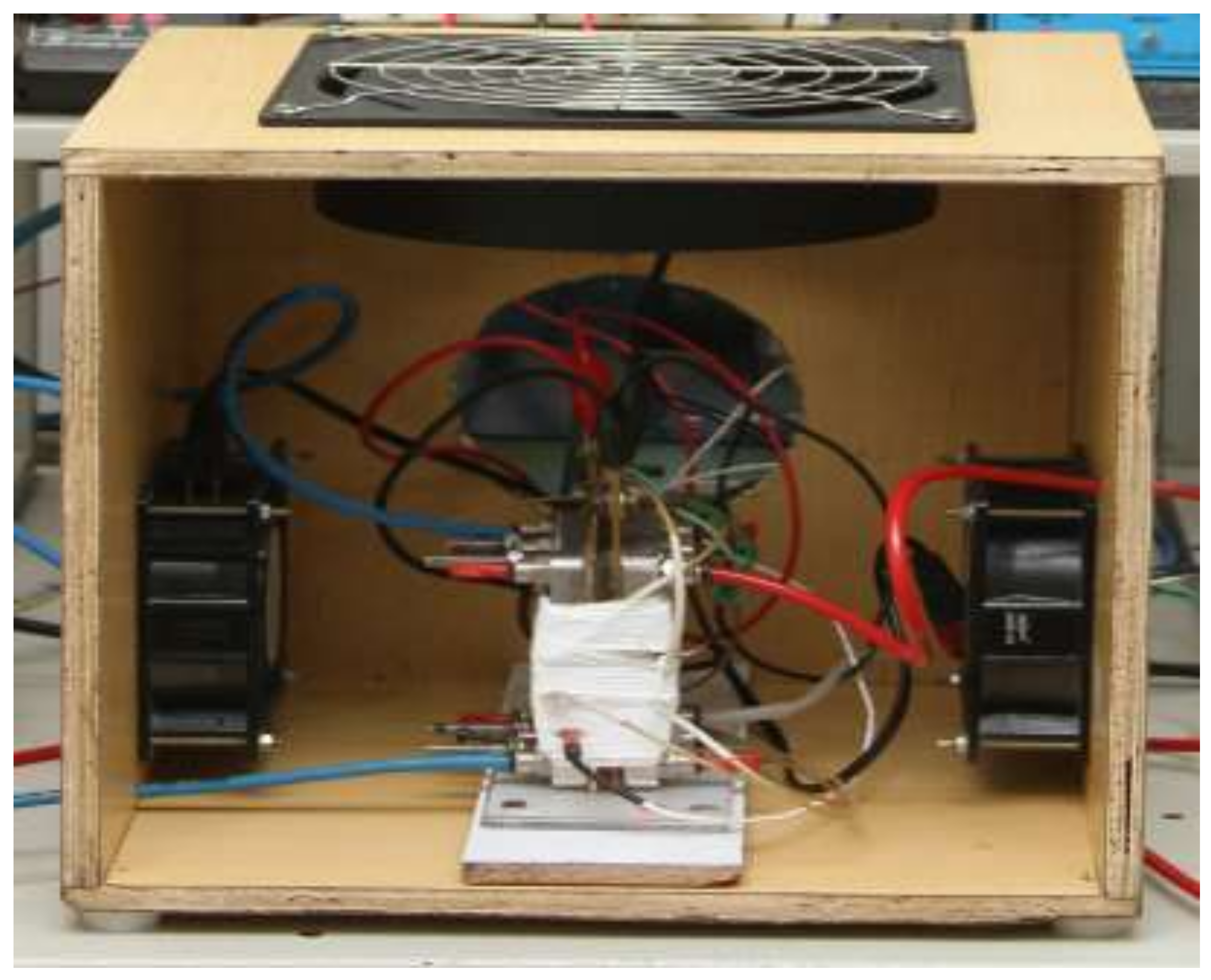
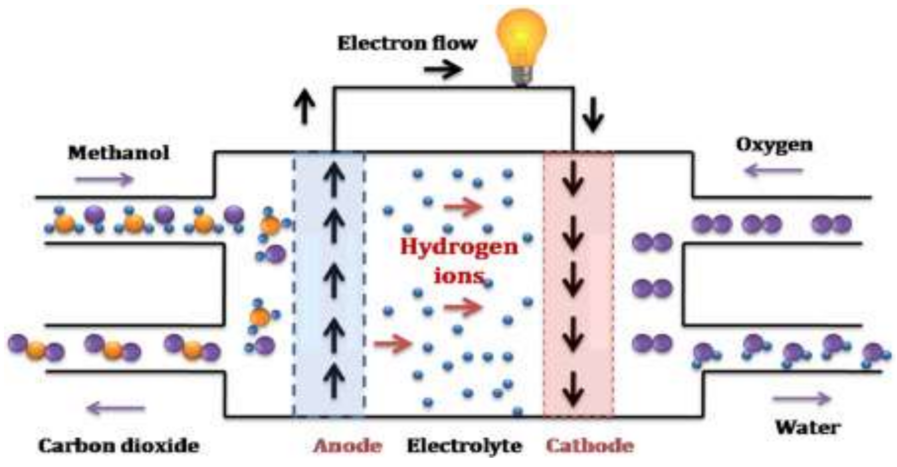
2.2. Real-Time Experimentation

In this research work, a single DMFC system was designed with a 45 cm2 active cross-sectional area (Figure 2). The cell was molded into a frame of a fiber-reinforced Teflon-coated jacket and was kept between two graphite blocks. Flow grooves for methanol and oxygen flow were provided in this system. The flow field comprised a series of 25 parallel channels with a 2 mm depth, a 1 mm wide rib and a 1 mm groove [18]. A provision for the tapping current and voltage measurement was provided. Electrical plate type heaters were placed behind each of the graphite blocks to heat the cell for achieving the desired operating temperature. Methanol solution was circulated with the peristaltic pump. Oxygen was supplied with 2 atm pressure. Catalysts of Pt-Ru/C and Pt/C were loaded at concentrations of 2 mg/cm2 at anode and cathode, respectively. Nafion 117, a polymer electrolyte membrane, was used in MEA preparations. It has a high protonic conductivity, zero electronic conductivity, excellent mechanical stability, and low resistance. This polymer electrolyte membrane also acts as a separator between the anode and the cathode. A graphite plate is commonly used as reactant distributor cum current collector [19,20]. The reactions involved in the DMFC operation were as follows:
A n o d e   r e a c t i o n :   C H 3 O H + H 2 O C O 2 + 6 H + +   6 e Cathode   reaction : 3 / 2 O 2 + 6 H + + 6 e + 3 H 2 O Overall   reaction : C H 3 O H + 3 / 2 O 2 C O 2 + 2 H 2 O

3. Results and Discussion

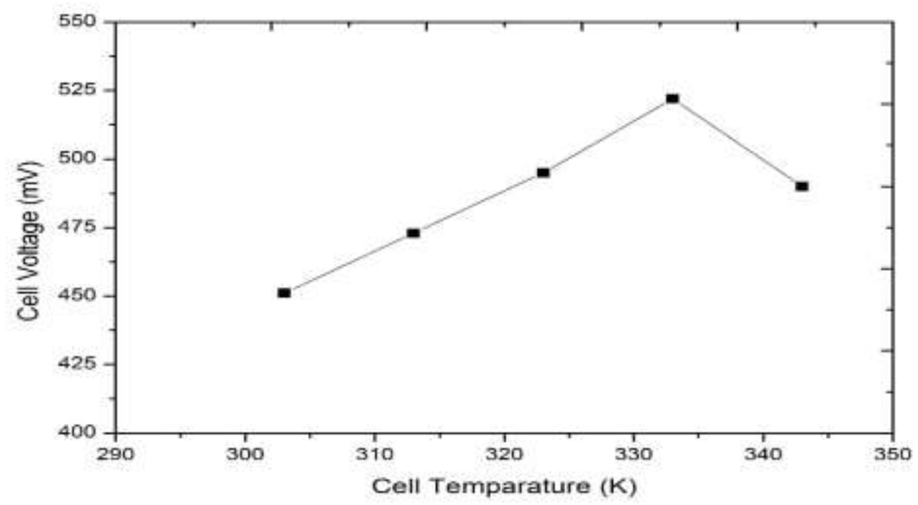
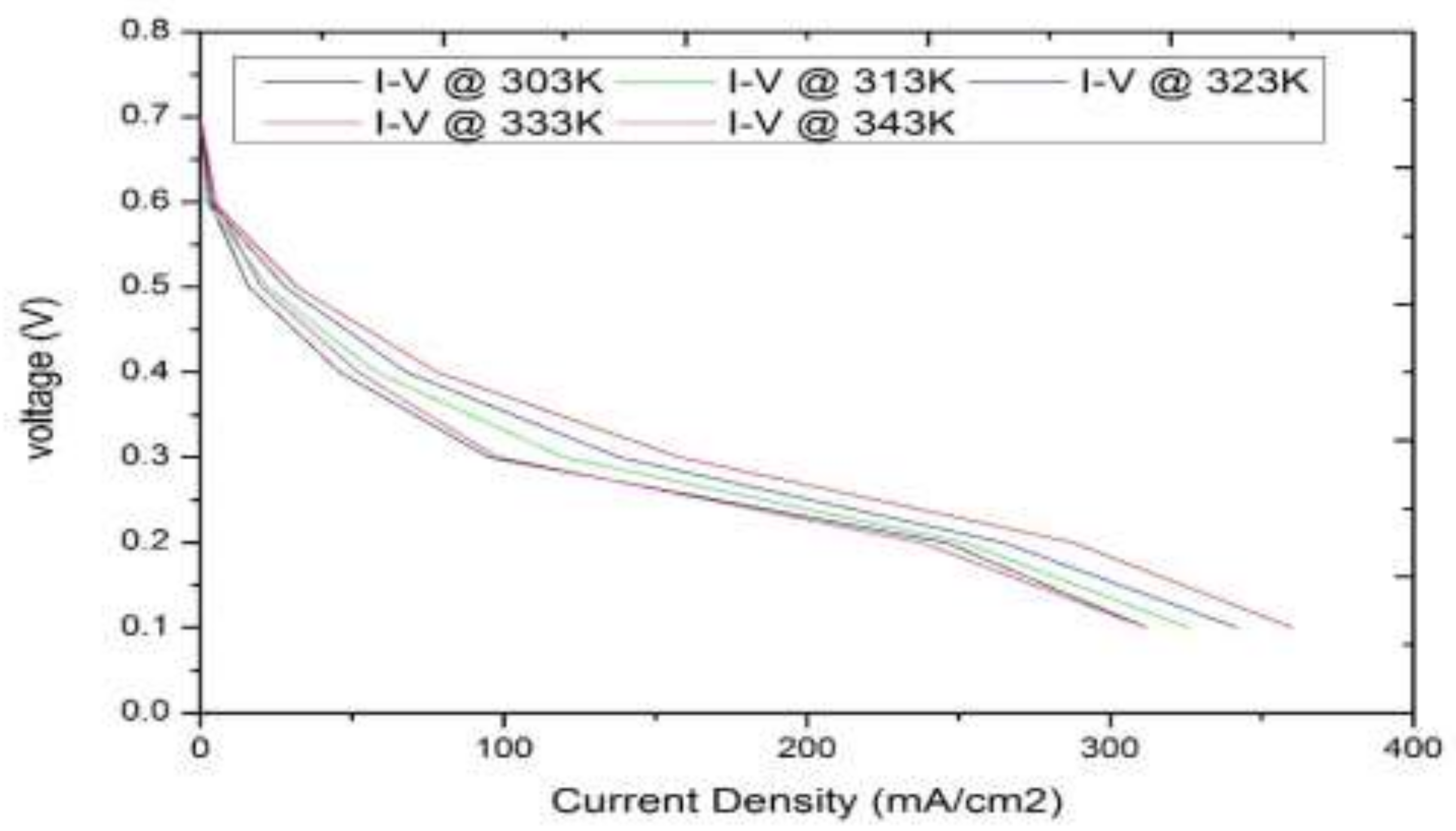
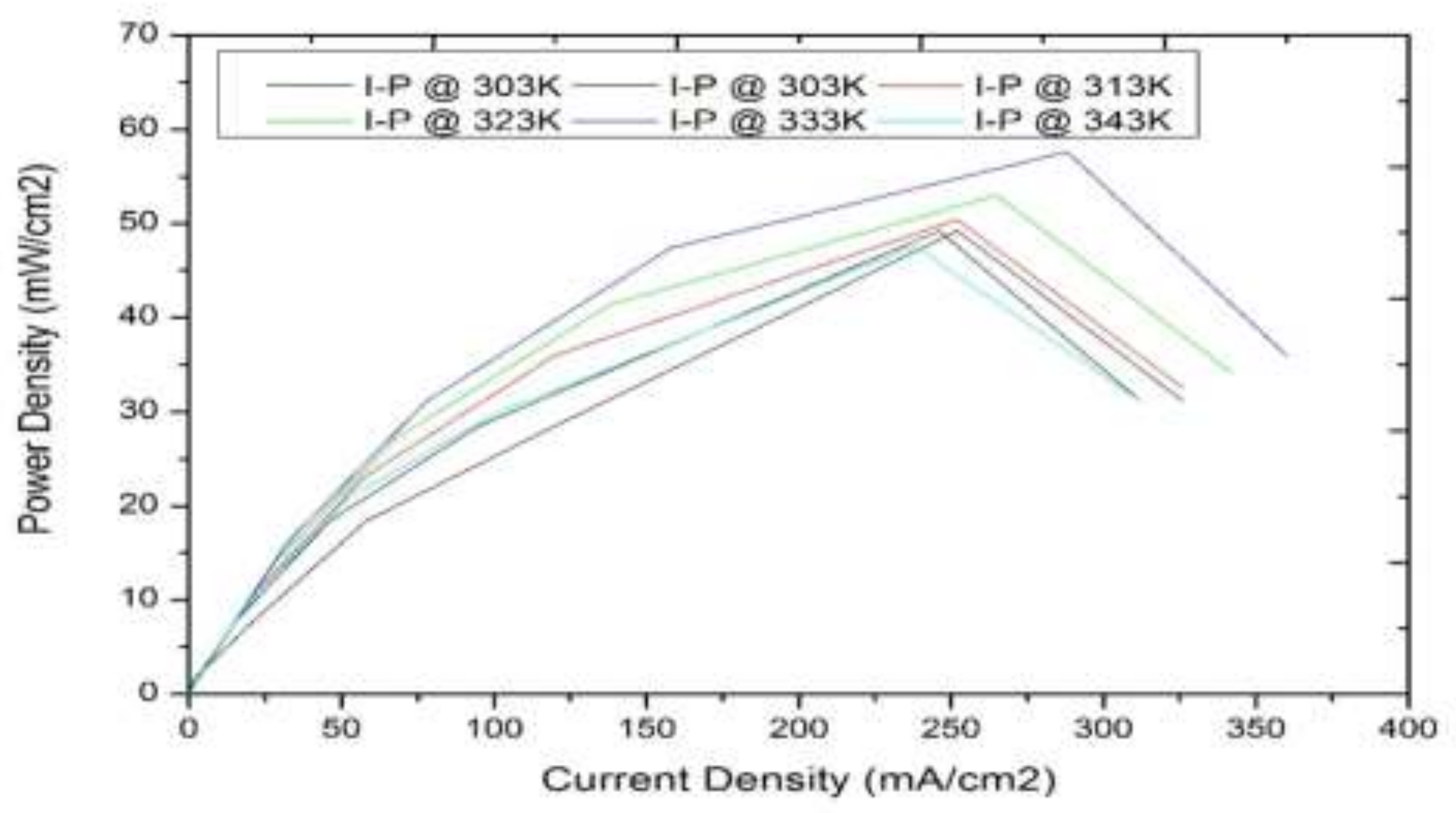
3.1. Model-Based Simulation

A program written in MATLAB with the mathematical modelling equations of the DMFC was simulated as discussed in Section 2.1. In order to find out the most influencing variable of the DMFC, the analysis was carried out for cell temperature, methanol flow rate, and methanol concentration. During the simulation, the effect of different operating temperatures between 303 K and 343 K, different methanol flow rates in the ranges of 0.25 CCM to 2 CCM and different methanol concentrations in the ranges of 0.25 M to 2 M were recorded. The results obtained are plotted in Figure 3, Figure 4 and Figure 5.
It was also observed from Figure 3 and Figure 4 that the DMFC output voltage increased the methanol flow rate by up to 1 CCM and increased the 1M methanol concentration, thereafter, (i.e., greater than 1CCM methanol flow rate and higher than 1M methanol concentration) DMFC output voltage did not vary significantly and remained constant due to the methanol crossover to cathode. It was also observed from Figure 5 that the output voltage of the DMFC increased linearly with an increase in temperature up to 333 K and decreased beyond that due to the dry-out effect in the cell. From the dynamic studies, it is clear that the temperature is the most influencing variable on the output voltage of DMFC. Hence, this working temperature was selected as a manipulated variable for further investigation.
Step response analysis was carried out in simulation to validate the developed mathematical model and its behavior. Step input changes were given at the operating temperatures of 313 K, 323 K, and 333 K (25%, 50%, 75% of the cell temperature) with ± 10% and ± 15%. Step response of the system at 25% of the cell temperature for a step change of ± 10%, and a step change of ± 15% of cell temperature were observed and are given in Figure 6. Similar runswere conducted at 50% of the cell temperature and 75% of cell temperature and are recorded in Figure 7 and Figure 8, respectively. From the step response curves, it was concluded that the developed model was behaving linearly in these operating temperatures.

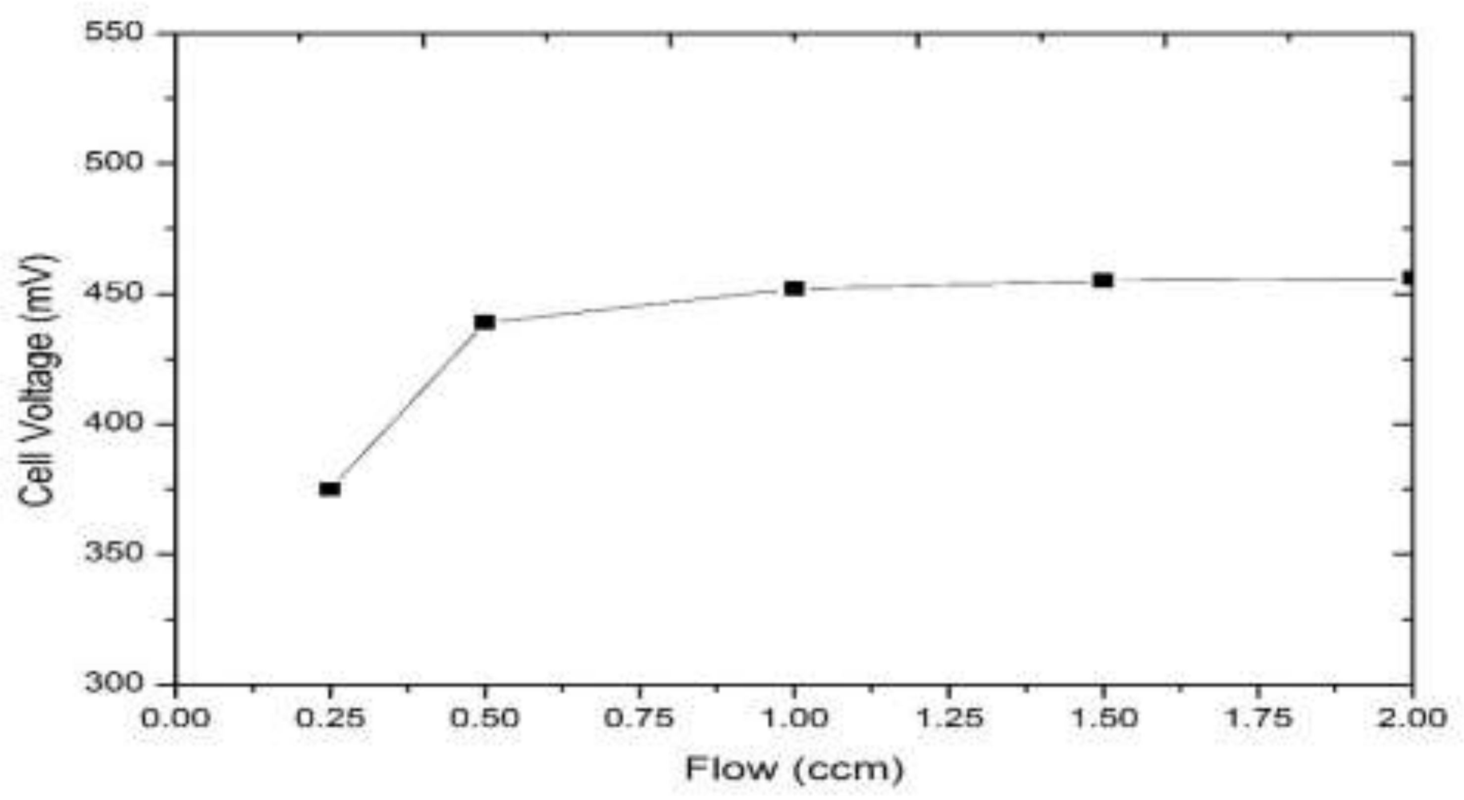
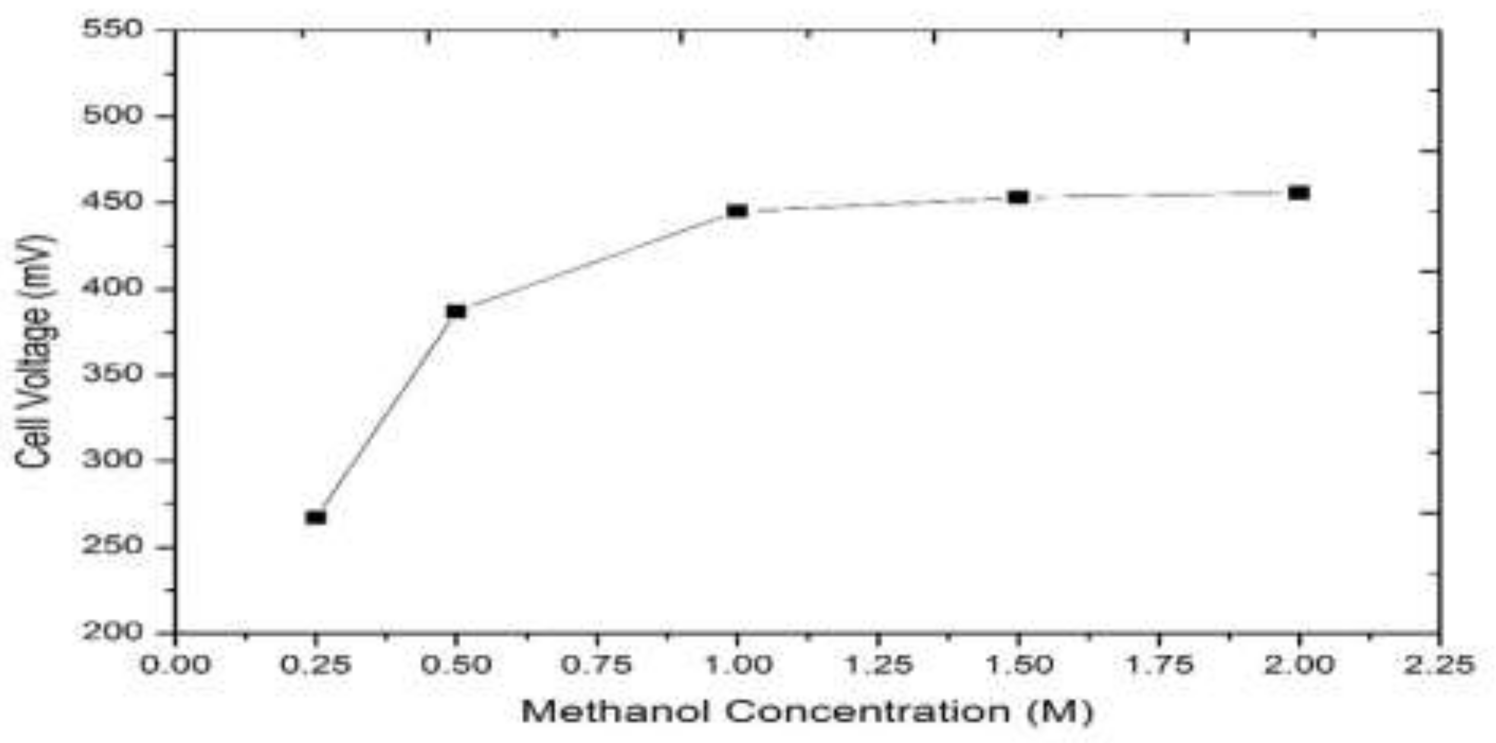
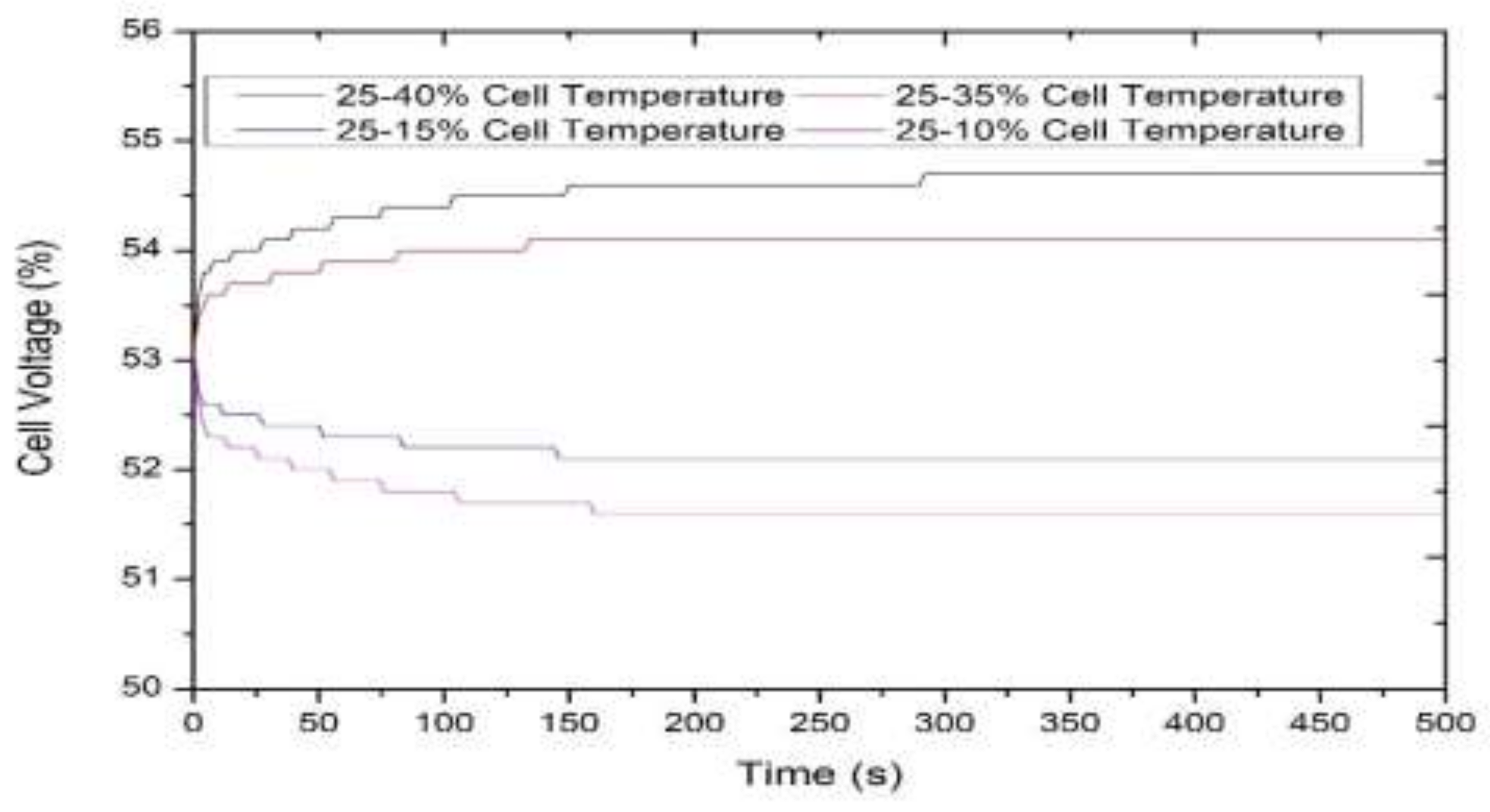
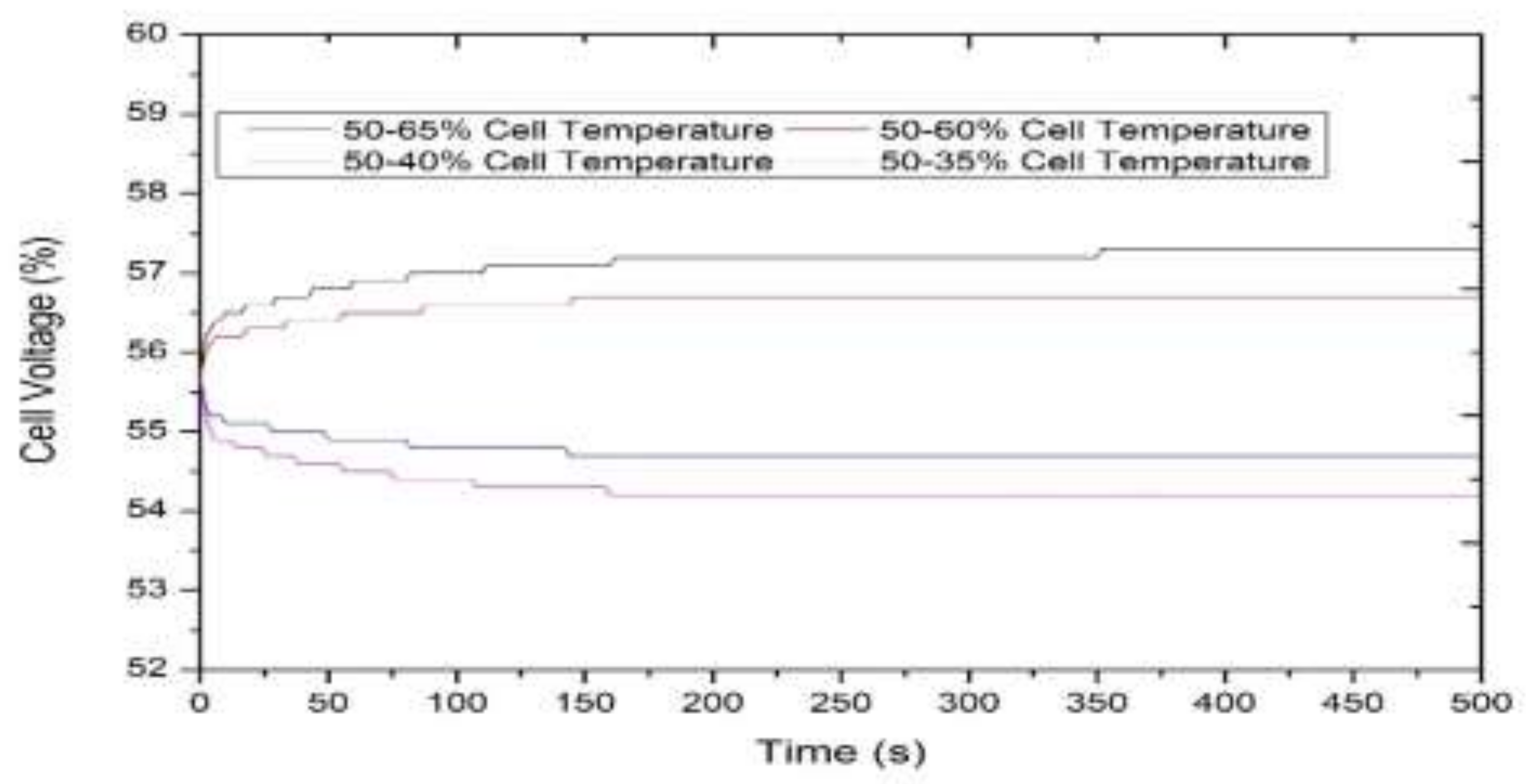
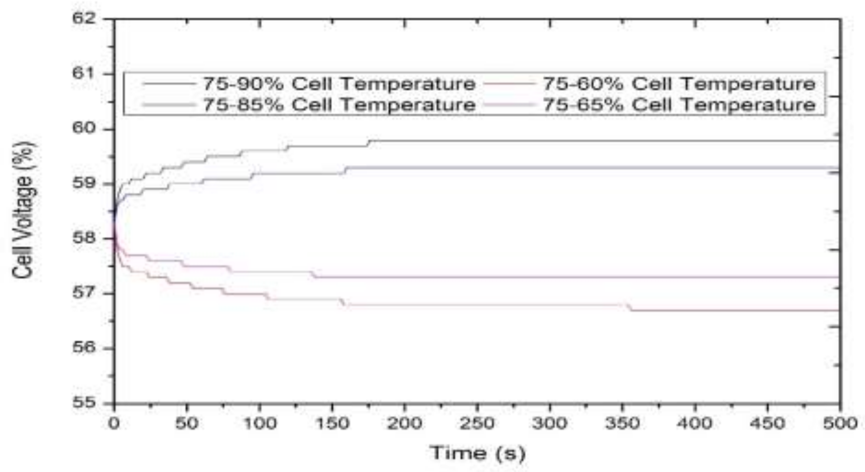
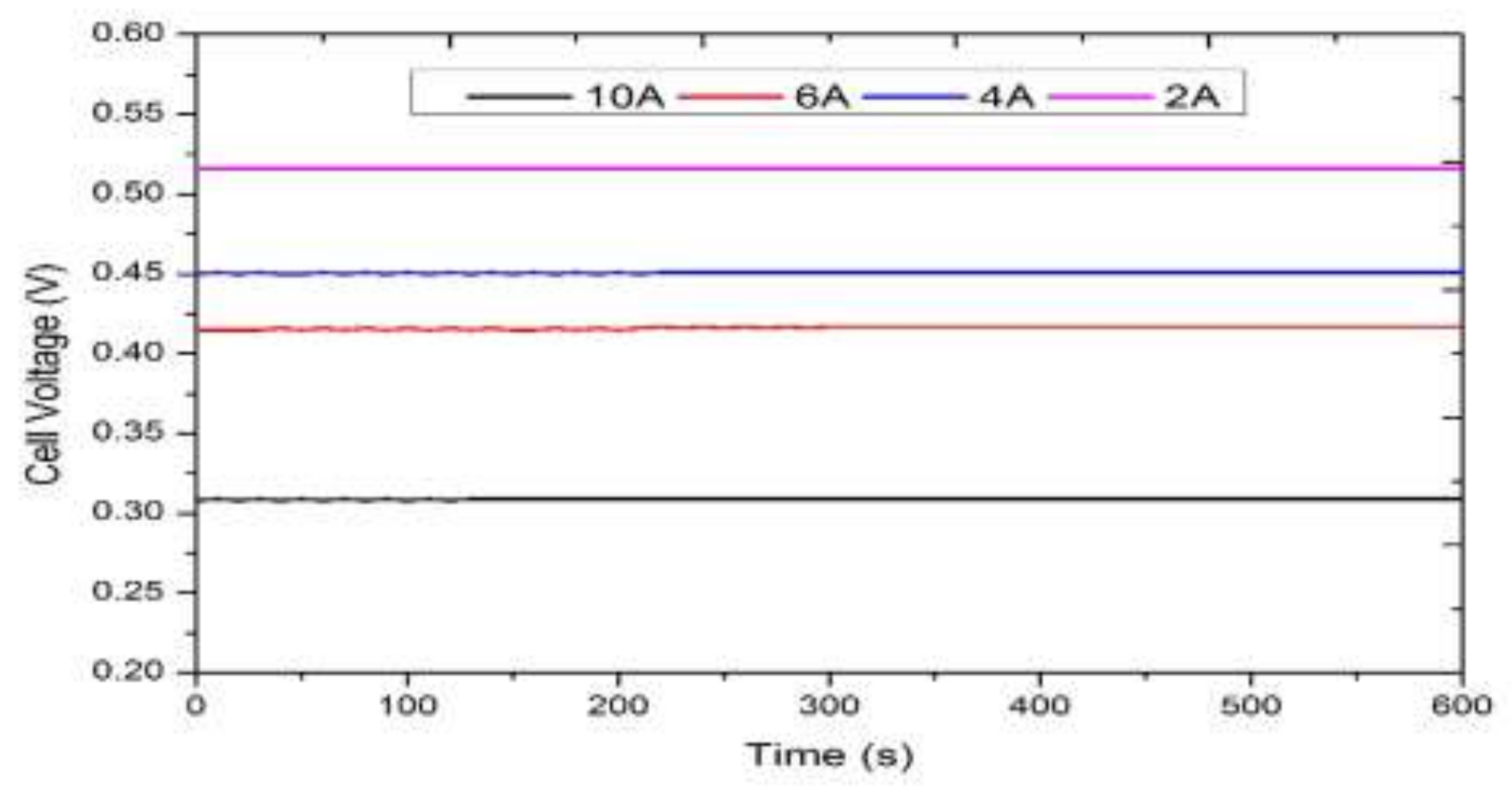
3.2. Real-Time Experimentation

Experimentation of the squoval-shaped manifold holedesign(SSMHD)-based DMFC was carried out with a Pt-Ru/C catalyst combination in order to determine the optimum operating temperature (TCell) of the DMFC with a methanol concentration of 1 M and a methanol flow rate of 1 mL/min. The output voltage of DMFC for a defined current was measured using an electronic load bank and the performance of DMFC was analyzed. Voltage and power density obtained during the run of the experiment against current density were plotted (I–V Curve and I–P Curve) and are shown in Figure 9 and Figure 10, respectively.
It was observed from Figure 9 and Figure 10 that an increase in the DMFC temperature from 303 K (30°C) to 333 K (60°C) led to an increase in DMFC performance, butfor a further increase in temperature beyond its boiling point 333 K (60°C), DMFC performance was reduced due to the dry-out effect. Hence, it is reported that 333 K (60°C) is the optimum operating temperature at which a maximum power density of 57.6 mW/cm2 was obtained for a squoval-shaped manifold design (SSMD)-incorporated direct methanol fuel cell. In addition to the studies on temperature, the durability of a DMFC at different load currents, namely 2A, 4A, 6A, and 10A, was also studied.Output voltages were recorded and are shown in Figure 11. It was confirmed by the consistent, steady output that the SSMD-based DMFC was durable at the optimized operating conditions, namely a DMFC temperature of 333 K, a methanol concentration of 1 M, and a methanol flow rate of 1 mL/min.

4. Conclusions

A direct methanol fuel cell (DMFC) is a particular type of fuel cell that has its own merits. In this work, a direct methanol fuel cell with a 45 cm2 activation area in the MEA, and a Pt-Ru/C catalyst at the anode was fabricated and tested with the squoval-shaped manifold hole design-incorporated DMFC work station available in the laboratory. Performance of the DMFC was evaluated with different operating parameters, namely cell temperature, methanol flow rate, and methanol concentration in simulation. From the simulation results, it was concluded that cell temperature was the most influencing process variable. From the results, the optimum temperature (TCell) of the DMFC operation was identified as 333 K. Real-time experimentation was carried out with different cell temperatures, and the results were recorded. It was observed from the experimental data that the maximum power density of 57.6 mW/cm2 at 288 mA/cm2 was achieved with the said operating temperature of 333 K. With this operating temperature, the durability of the DMFC was also verified at different load currents and found to be durable.

Author Contributions

This paper is come to the final shape with the conceptualization of R. Govindarasu and recourse of S. Somasundaram. All authors have read and agreed to the published version of the manuscript.

Funding

This research received no external funding.

Acknowledgments

The authors are grateful to P. Kanthabhaba, Former Professor and Head, Department of Chemical Engineering, Annamalai University, Chidambaram-608002, India.

Conflicts of Interest

The authors declare no conflict of interest.

References

  1. Dinesh, J.; Easwaramoorthi, M.; Muthukumar, M. State of Research Developments in Direct Methanol Fuel cell. Int. J. Eng. Trends Technol. 2017, 43, 284–296. [Google Scholar] [CrossRef]
  2. Dillon, R.; Srinivasan, S.; Arico, S.A.; Antonucci, V. International activities in DMFCR&D: Status of technologies and potential applications. J. Power Sources 2004, 127, 112–126. [Google Scholar]
  3. Vielstich, W.; Gasteiger, H.; Lamm, A. Handbook of Fuel Cell: Fundamentals, Technology, Applications; John Wiley & Sons: New York, NY, USA, 2003. [Google Scholar]
  4. Arico, S.; Srinivasan, S.; Antonucci, V. DMFCs: From Fundamental Aspects to Technology Development. Fuel Cells 2001, 1, 133–161. [Google Scholar] [CrossRef]
  5. Bostaph, J.; Xie, C.G.; Pavio, J.; Fisher, A.M.; Mylan, B.; Hallmark, J. Design of a 1-W direct methanol fuel cell system in Direct Methanol Fuel Cell. In Proceedings of the 40 th Power Sources Conference, Cherry Hill, NJ, USA, 10–13 June 2002; pp. 211–214. [Google Scholar]
  6. Venkatkarthick, R.; Elamathi, S.; Sangeetha, D.; Balaji, R.; Kannan, B.S.; Vasudevan, S.; Davidson, D.J.; Sozhan, G.; Ravichandran, S. Studies on polymer modified metaloxideanodeforoxy gen evolution reaction in saline water. J. Electroanal. Chem. 2013, 697, 1–4. [Google Scholar] [CrossRef]
  7. Balaji, R.; Kannana, B.S.; Lakshmi, J.; Senthil, N.; Vasudevan, S.; Sozhan, G.; Shukla, A.K.; Ravichandran, S. An alternative approach to selective seawater oxidation for hydrogen production. Electrochem. Commun. 2009, 11, 1700–1702. [Google Scholar] [CrossRef]
  8. Wang, C.Y. Principles of direct methanol fuel cells for portable and micropower. In Mini-Micro Fuel Cells; Springer: Ankara, Turkey, 2008; pp. 235–242. [Google Scholar]
  9. Chang, J.Y.; Kuan, Y.D.; Lee, S.M. Experimental Investigation of a Direct Methanol Fuel Cell with Hilbert Fractal Current Collectors. Hindawi-J. Chem. 2014, 2014, 371616. [Google Scholar] [CrossRef]
  10. Balasinga, S.K.; Nallathamb, K.S.; Jabbar, M.H.A.; Ramadoss, A.; Kamaraj, S.K.; Nanomaterials, M.K. Electrochemical Energy Conversion and Storage Technologies. Hindawi-J. Nanomater. 2019. [Google Scholar] [CrossRef]
  11. Yuan, W.; Fang, G.; Li, Z.; Chen, Y.; Tang, Y. Using Electrospinning-Based Carbon Nanofiber Webs for Methanol Crossover Control in Passive Direct Methanol Fuel Cells. Materials 2018, 11, 71. [Google Scholar] [CrossRef] [PubMed] [Green Version]
  12. Ramesh, V.; Krishnamurthy, B. Modeling the transient temperature distribution in a Direct Methanol fuel cell. J. Electroanal. Chem. 2018, 809, 1–7. [Google Scholar] [CrossRef]
  13. Youngseung, N.; Zenith, F.; Krewer, U. Increasing Fuel Efficiency of Direct Methanol Fuel Cell Systems with Feed forward Control of the Operating Concentration. Energies 2015, 8, 10409–10429. [Google Scholar] [CrossRef] [Green Version]
  14. Ohenoj, M.; Ruusunen, M.; Leivisk, K. Hierarchical Control of an Integrated Fuel Processing and Fuel Cell System. Materials 2019, 12, 21. [Google Scholar] [CrossRef] [PubMed] [Green Version]
  15. Simoglou, A.; Argyropoulos, P.; Martin, E.B.; Scott, K.; Morris, A.J.; Taama, W.M. Dynamics modeling of the voltage response of direct methanol fuel cell sandstacks Part I: Mode development and validation. Chem. Eng. Sci. 2001, 56, 6761–6772. [Google Scholar] [CrossRef]
  16. Govindarasu, R.; Parthiban, R.; Bhaba, P.K. Recent evolutions in modelling of Direct Methanol Fuel Cell. Elixir Int. J. Chem. Eng. 2014, 72, 25428–25433. [Google Scholar]
  17. Maynard, H.L.; Meyers, J.P. Miniature fuel cells for portable power: Design considerations and challenges. J. Vac. Sci. Technol. 2002, 20, 1287–1297. [Google Scholar] [CrossRef]
  18. Govindarasu, R.; Parthiban, R.; Bhaba, P.K. Investigation of Flow Maldistribution in proton exchange membrane fuel cell. Int. J. Renew. Energy Res. 2012, 2, 653–656. [Google Scholar]
  19. Manokaran, A.; Vijayakumar, R.; Sridhar, P.; Pitchumani, S.; Shukla, K. A self-supported Direct methanol fuel cell system. J. Chem. Sci. 2011, 123, 343–347. [Google Scholar] [CrossRef]
  20. Premkumar, S.; Prabhakar, S.; Lingeswaran, K.; Ramnathan, P. Development of Direct Methanol Fuel Cell and Improving the efficiency. Middle-East J. Sci. Res. 2014, 20, 1277–1280. [Google Scholar]
Figure 1. Real-time experimental setup of the direct-methanol fuel cell (DMFC) system.
Processes 08 00353 g001
Figure 2. Schematic diagram of the direct methanol fuel cell system.
Processes 08 00353 g002
Figure 3. Effect of methanol flowrate.
Processes 08 00353 g003
Figure 4. Effect of methanol concentration.
Processes 08 00353 g004
Figure 5. Effect of cell temperature.
Processes 08 00353 g005
Figure 6. Step response of DMFC at 25% ofthe operating temperature.
Processes 08 00353 g006
Figure 7. Step response of DMFC at 50% of the operating temperature.
Processes 08 00353 g007
Figure 8. Step response of DMFC at 75% of the operating temperature.
Processes 08 00353 g008
Figure 9. CCH3OM: Steady-state current density–voltage curve.
Processes 08 00353 g009
Figure 10. CCH3OM: Steady-state current density–power density curve.
Processes 08 00353 g010
Figure 11. Durability test on a squoval-shaped manifold hole design-based DMFC.
Processes 08 00353 g011
Table 1. Equation for the variation of CCH3OH and theanode/cathode overpotential.
S.No.Variation of CCH3OH and The Anode/Cathode Over Potential
1 d C C H 3 O H d t = 1 τ C C H 3 O H F C C H 3 O H A S V N C H 3 O H A S V r 1
2 d η A d t   =   1 C a   i C e l l F 3 r 1 + 3 r 2
3 d η c d t   =   1 C c   i C e l l   6 F r 5 + N C H 3 O H
Table 2. Equation for coverage of adsorbed species at the anode.
S.No.Coverage of Adsorbed Species at Anode
1 d P t 3 C O H d t = 1 γ C t * r 1 r 3
2 d θ R u O H d t =   1 γ C t *   ( 3 r 2 2 r 3 r 4 )
3 d P t 3 C O O H d t = 1 γ C t * r 3 r 4

