Article

Absolute Stability Condition Derivation for Position Closed-Loop System in Hydraulic Automatic Gauge Control

1
National Research Center of Pumps, Jiangsu University, Zhenjiang 212013, China
2
School of Hydraulic Energy and Power Engineering, Yangzhou University, Yangzhou 225002, China
3
Hebei Provincial Key Laboratory of Heavy Machinery Fluid Power Transmission and Control, Yanshan University, Qinhuangdao 066004, China
4
State Key Laboratory of Fluid Power and Mechatronic Systems, Zhejiang University, Hangzhou 310027, China
*
Authors to whom correspondence should be addressed.
Processes 2019, 7(10), 766; https://doi.org/10.3390/pr7100766
Submission received: 18 September 2019 / Revised: 11 October 2019 / Accepted: 12 October 2019 / Published: 18 October 2019
(This article belongs to the Special Issue Smart Flow Control Processes in Micro Scale)

Abstract

:
In the metallurgical industry, hydraulic automatic gauge control (HAGC) is a core mechanism for thickness control of plates used in the rolling process. The stability of the HAGC system’s kernel position closed-loop is key to ensuring a process with high precision, speed and reliability. However, the closed-loop position control system is typically nonlinear, and its stability is affected by several factors, making it difficult to analyze instability in the system. This paper describes in detail the functioning of the position closed-loop system. A mathematical model of each component was established using theoretical analysis. An incremental transfer model of the position closed-loop system was also derived by studying the connections between each component. In addition, based on the derived information transfer relationship, a transfer block diagram of disturbance quantity of the system was established. Furthermore, the Popov frequency criterion method was introduced to ascertain its absolute stability. The results indicate that the absolute stability conditions of the position closed-loop system are derived in two situations: when spool displacement is positive or negative. This study lays a theoretical foundation for research on the instability mechanism of an HAGC system.

1. Introduction

The development of “intelligent” and “green” manufacturing equipment has propelled the metallurgical industry to pursue intelligence in their rolling equipment, and to ensure high quality of plates and strips used in the industry [1]. However, it has been demonstrated that mass production often results in instability in the rolling process, hindering high-precision and intelligent development. The hydraulic automatic gauge control (HAGC) system is a core mechanism for thickness control of plates used in the rolling process. Its function is to automatically adjust the roll gap of a rolling mill when external disturbance factors change, so as to ensure that the target thickness of the strip is within the index range. The stability of the system’s closed-loop kernel position is key to ensuring a process with high precision, speed and reliability.
The HAGC system is complex with multiple links—it is nonlinear and has several parameters that influence its functioning. Because the system’s working mechanism is multifaceted, it is difficult to analyze its instability, a problem that researchers in the engineering field have been trying to solve [2,3,4]. Scholars are currently studying the dynamic characteristics of the HAGC system. Roman et al. [5] researched the thickness control of cold-rolled strips and proposed a system that compensates for errors caused by the hydraulic servo-system used for positioning of the rolls. Hu et al. [6] analyzed the rolling characteristics of the tandem cold-rolling process and proposed an innovative multivariable optimization strategy for thickness and tension based on inverse linear quadratic optimal control. Sun et al. [7] proposed a dynamic model of a cold rolling mill based on strip flatness and thickness integrated control. They conducted dynamic simulation of the rolling process, obtaining information on thickness and flatness. Prinz et al. [8] compared two different AGC setups and developed a feed forward approach for lateral asymmetry of entry thickness. They also developed a new feed forward control approach for the thickness profile of strips in a tandem hot rolling mill [9]. Kovari [10] studied the effect of internal leakage in a hydraulic actuator on dynamic behaviors of the hydraulic positioning system. Li et al. [11] presented a robust output-feedback control algorithm with an unknown input observer for the hydraulic servo-position system in a cold-strip rolling mill with uncertain parameters, immeasurable states and unknown external load forces. Sun et al. [12] introduced key technical features and new technology of the improved cold strip mill process control system: system architecture, hardware configuration and new control algorithms. Yi et al. [13] analyzed HAGC’s step response test process: they simulated and established a transfer function model of the test using matrix and laboratory (MATLAB). Liu et al. [14] built a vibration system dynamic model with hydraulic-machinery coupling for four-stand tandem cold rolling mills. The model integrated MATLAB software with automatic dynamic analysis of mechanical systems (ADAMS). Wang et al. [15] established a mathematical model for position–pressure master–slave control of a hydraulic servo system, then simulated the system with AMESim and MATLAB. Hua et al. [16] provided rigorous proof of the exponential stability of the HAGC system by implementing the Lyapunov stability theory. Zhang et al. [17] studied the control strategy of a hydraulic shaking table based on its structural flexibility. Qian and Wang et al. [18,19] researched the effects of important elements, such as valves [20,21,22], pumps [23,24,25,26] and rotors [27], on stability. The influence of excitation forces on the vibration of a pump and measures of noise reduction were studied by Ye et al. [28,29]. Bai et al. [30,31,32] studied the vibration in a pump under varied conditions. These researchers have had great results with their experiments, providing the basis for further study. However, theoretical derivation and research on the instability mechanism of an HAGC system is still relatively rare.
Scholars have previously applied the Lyapunov method to study the absolute stability of a nonlinear closed-loop control system [33,34]. However, this method has certain reservations, and application of the required Lyapunov function is difficult [35,36]. In 1960, V. M. Popov created a frequency criterion method to determine absolute stability of a nonlinear closed-loop control system. It relied on a classical transfer function and eliminated the dilemma of reconstructing a decision function. This method is of great applicatory value and has been widely recognized by scholars worldwide [37,38]. However, there are still rare results via applying the Popov frequency criterion method to the stability of the HAGC system. The HAGC system is a typical nonlinear closed-loop control system with many influence parameters, and its dynamic characteristics are complex and changeable. When the system is in certain working states, the nonlinear vibration may be induced [39,40]. If the instability mechanism cannot be effectively mastered and controlled in time, a major vibration accident may occur in the system [41,42,43]. Therefore, it is very important and urgent to explore the instability mechanism of the HAGC system and solve the problem of dynamic instability and inhibition from the source. Conducting the theoretical derivation and in-depth study of the instability mechanism of the HAGC system by using Popov frequency criterion method, is a new technique which needs to be further explored.
In this paper, the Popov frequency criterion method is introduced to theoretically deduce the absolute stability condition for key position closed-loop system in HAGC. The purpose is to lay a theoretical foundation for the study on the instability mechanism of the HAGC system. In Section 2, the mathematical model of the position closed-loop system is established. In Section 3, the incremental transfer model of the position closed-loop system is deduced. In Section 4, the absolute stability condition for the position closed-loop system is deduced. In Section 5, some conclusions are provided.

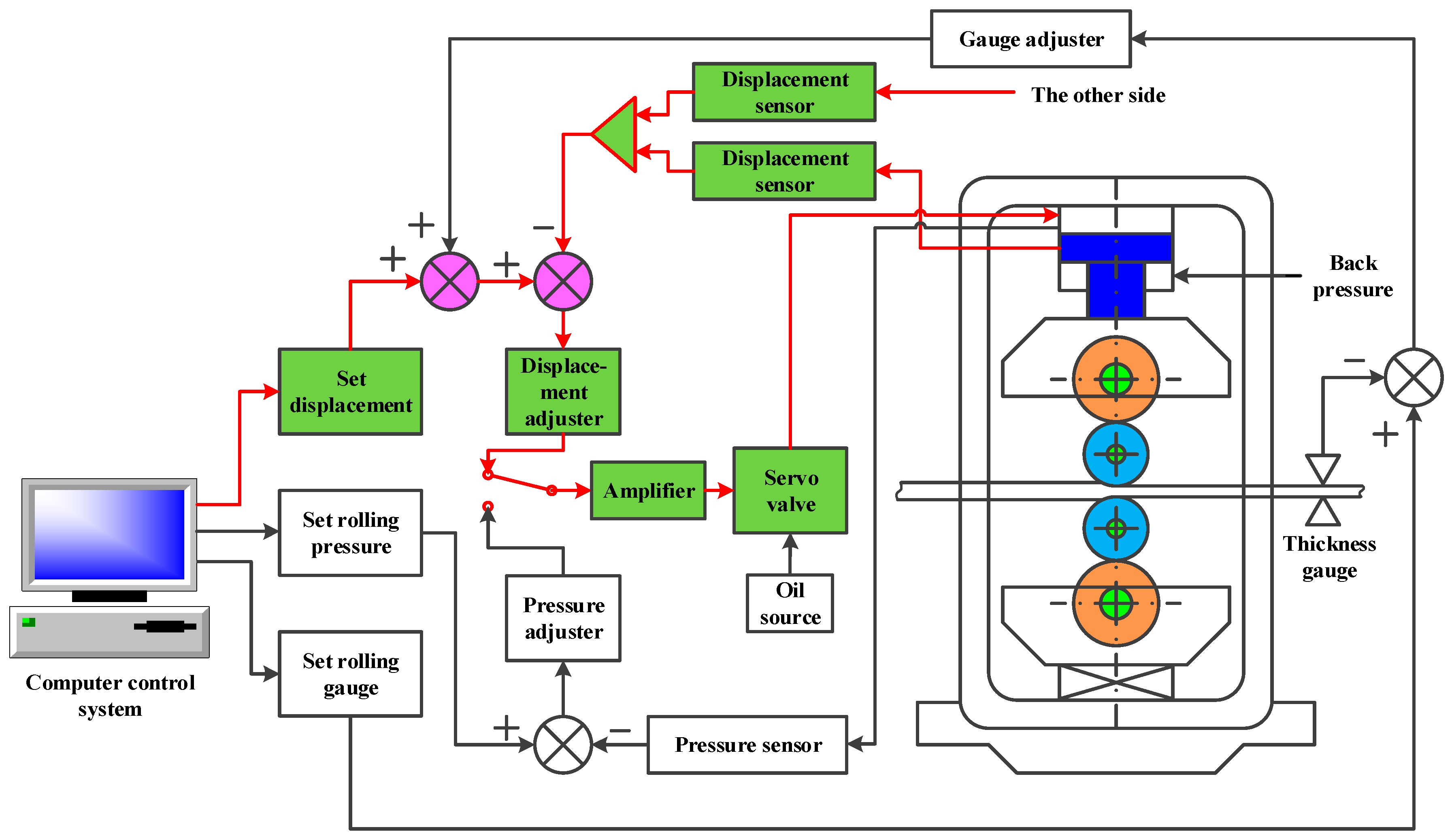
2. Mathematical Model of Position Closed-Loop System

The HAGC system is mainly controlled by electro-hydraulic servo valve and oil cylinder to realize the setting and adjustment of roll gap or rolling pressure. In terms of control function, a complete HAGC system is composed of several automatic control systems. The most important three control loops are as follows: cylinder position closed loop, rolling pressure closed loop and thickness gauge monitoring closed loop, as shown in Figure 1.
As the basis of the whole thickness control, cylinder position closed loop is used to control the displacement in a timely and accurate manner with the change of rolling conditions, so as to achieve the setting and controlling of the roll gap. In the position closed-loop system, the measured displacement value is negatively fed back to the signal input end and compared with the given displacement value. If there is a deviation, it will be adjusted by the displacement adjuster and converted into current signal by the power amplifier and further sent to the electro-hydraulic servo valve. After the servo valve obtains the current signal, it will control the flow into the working chamber of the cylinder through the movement of valve spool and then adjust the piston displacement of the cylinder until the feedback value is equal to the set value.

2.1. Mathematical Model of Controller

The controller generally adopts proportion-integration-differentiation (PID) adjuster and its dynamic transfer function can be expressed as:
G c ( s ) = K p ( 1 + 1 T i s + T d s ) ,
where K p is proportionality coefficient, T i is integral time constant, T d is differential time constant and s is the Laplace operator.

2.2. Mathematical Model of Servo Amplifier

The function of the servo amplifier is to convert voltage signal into current signal and then control the servo valve to realize flow regulation. Since the response time of the servo amplifier is extremely short, it can be treated as a proportional component and its dynamic transfer function is:
K a = I U
where I is the output current (A), U is the input voltage (V) and K a is amplification coefficient (A/V).

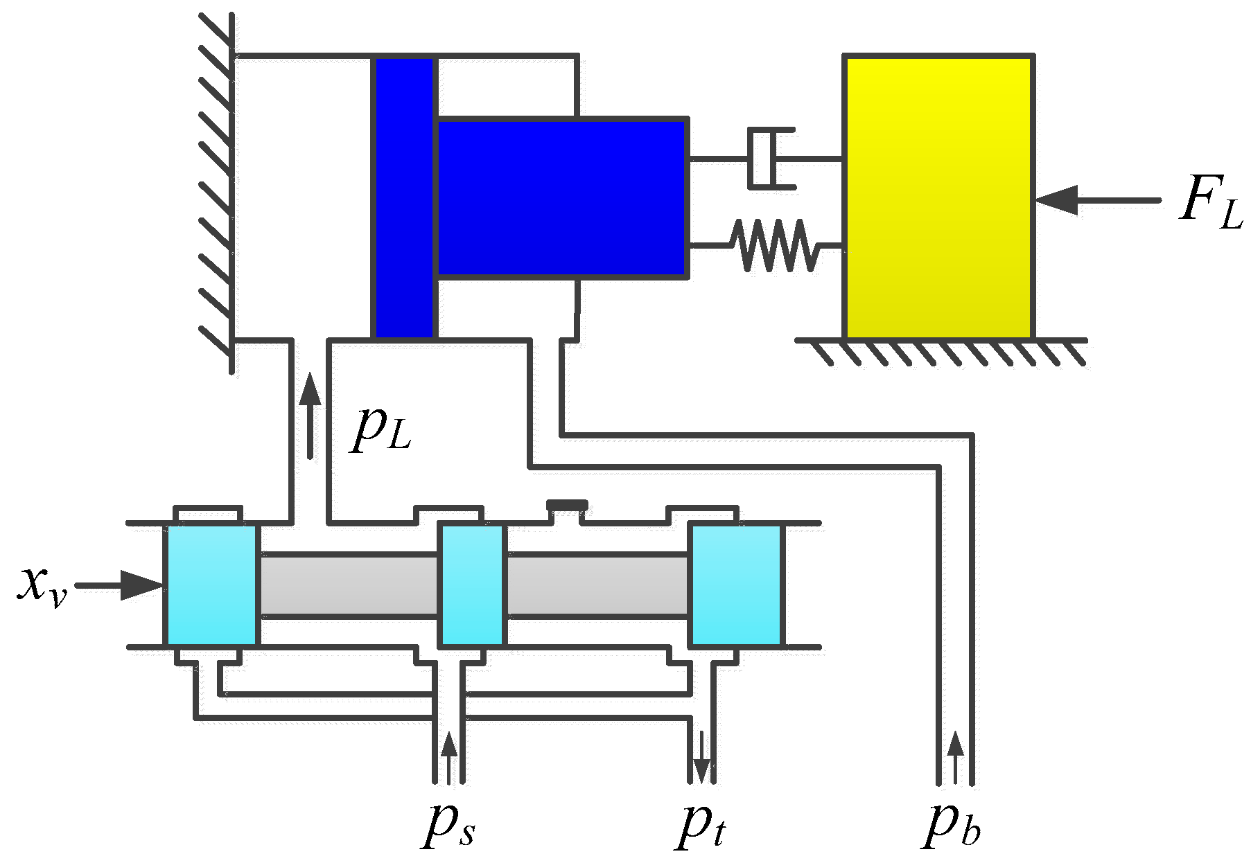
2.3. Mathematical Model of Hydraulic Power Mechanism

The hydraulic power mechanism of HAGC system is mainly realized by controlling the motion of the hydraulic cylinder with the electro-hydraulic servo valve. Its structural principle is displayed in Figure 2. In order to improve the response performance of the system, the servo valve is generally used to control the rodless chamber of the hydraulic cylinder, and the rod chamber of the hydraulic cylinder is supplied with oil at a constant pressure.
When the servo valve works in the right position, the high pressure oil directly enters into the rodless chamber of the hydraulic cylinder. At this time, the piston rod of the cylinder drives the load to realize the pressing down action. When the servo valve operates in the left position, the fast lifting action of the roll can be achieved. During the rolling process, oil at a constant pressure of 1 MPa is always passed through the rod chamber to increase the damping of the system.

2.3.1. Flow Equation of Electro-Hydraulic Servo Valve

The function of the servo valve is to control the movement of the valve spool with weak current signal to achieve the control of high power hydraulic energy. There are many advantages such as small volume, high power amplification, fast response and high dynamic performance.
According to the working principle of the servo valve, when the spool displacement x v is used as the input and the load flow Q L is taken as the output, the basic flow equation of the servo valve can be obtained:
Q L = f ( x v , p L ) = { C d W x v 2 ( p s p L ) ρ x v 0 C d W x v 2 ( p L p t ) ρ x v < 0 ,
where C d is the flow coefficient of valve port, W is the area gradient of valve port (m), x v is the displacement of main spool (m), ρ is the hydraulic oil density ( kg / m 3 ), p s is the oil supply pressure (MPa), p t is the return pressure (MPa) and p L is the working pressure of rodless chamber of the hydraulic cylinder (MPa).
The relationship between spool displacement of the servo valve and input current can be expressed as:
G v ( s ) = x v I c = K s v s 2 ω s v + 2 ξ s v ω s v s + 1 ,
where I c is the input current of the servo valve (A), K s v is the amplification coefficient of the spool displacement on the input current (m/A), ω s v is the natural angular frequency of the servo valve (rad/s) and ξ s v is the damping coefficient of the servo valve ( N s / m ).
The servo valve also has nonlinear saturation characteristics and its input current is limited by:
I c = { I I < I N I N I I N ,
where I N is the rated current of the servo valve (A).

2.3.2. Basic Flow Equation of Hydraulic Cylinder

The flow from the servo valve into the hydraulic cylinder not only meets the flow required to push the piston, but also compensates for internal and external leakage in the cylinder, as well as the flow required to compensate for oil compression and chamber deformation.
The flow continuity equation for the rodless chamber of the hydraulic cylinder can be expressed by:
Q L = A p x ˙ 1 + C i p ( p L p b ) + C e p p L + V 0 + A p x 1 β e p ˙ L
where A p is the effective working area of the piston ( m 2 ), x 1 is the displacement of the piston rod (mm), C i p is internal leakage coefficient ( m 3 s 1 Pa 1 ), C e p is external leakage coefficient ( m 3 s 1 Pa 1 ), p b is the working pressure of the rod chamber (MPa), V 0 is the initial volume of the control chamber (including the oil inlet pipe and the rodless chamber) ( m 3 ) and β e is the bulk modulus of oil (MPa).
Since the change of piston displacement of the hydraulic cylinder is small when the hydraulic system is working stably, that is, A p x 1 < < V 0 , then the total volume of the hydraulic cylinder control chamber is approximately equal to the initial volume. In addition, with regard to the actual system, the external leakage is small and can be ignored. Therefore, the continuous flow equation of the hydraulic cylinder control chamber can be further written as:
Q L = A p x ˙ 1 + C i p ( p L p b ) + V 0 β e p ˙ L .

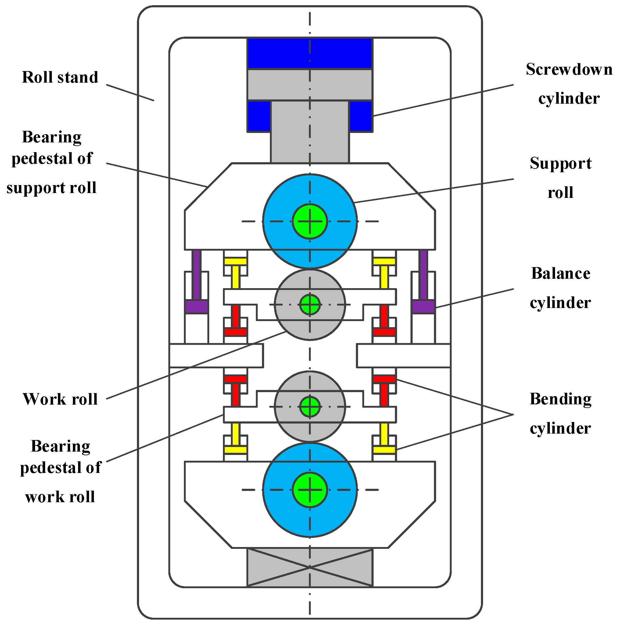
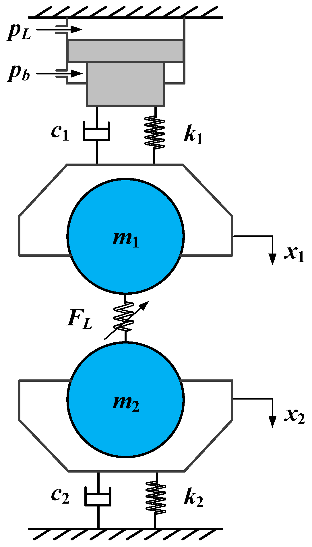
2.4. Mathematical Model of Load

The external load of the HAGC system consists of several sets of rolls with symmetrical structure. The basic structure of the load roll system of the commonly used four-high mill is shown in Figure 3. In consideration of the load roll system of the six-high mill, the basic structure is similar, and there is a set of intermediate rolls between the support roll and the work roll.
At present, in order to facilitate the analysis, the load roll system is mainly divided according to the lumped model and distribution parameter model, into single degree of freedom (DOF) load model and multi-DOF mass distribution load model, respectively. Moreover, numerous research studies indicate that the stiffness of the upper and lower roll systems of the rolling mill is asymmetrical. The analysis for the HAGC system according to the two-DOF mass distribution load model is more consistent with the actual working conditions [44,45].
In order to get closer to the actual working conditions, the modeling method of the load roll system is studied based on the two-DOF asymmetric mass distribution model. The upper roll system is used as a mass system and the lower roll system is utilized as another mass system, then the two-DOF mechanical model of the load roll system is established, as illustrated in Figure 4.
According to Newton’s second law, the load force balance equation of the HAGC system can be expressed as:
p L A p p b A b = m 1 x ¨ 1 + c 1 x ˙ 1 + k 1 x 1 + F L ,
F L = m 2 x ¨ 2 + c 2 x ˙ 2 + k 2 x 2 ,
where m 1 is the equivalent mass of moving parts of the upper roll system (URS) (kg); m 2 is the equivalent mass of the moving parts of the lower roll system (LRS) (kg); c 1 is the linear damping coefficient of moving parts of URS (N·s/m); c 2 is the linear damping coefficient of moving parts of LRS (N·s/m); k 1 is the linear stiffness coefficient between the upper frame beam and the moving parts of URS (N/m); k 2 is the linear stiffness coefficient between the lower frame beam and the moving parts of LRS (N/m); x 1 is the displacement of URS (mm); x 2 is the displacement of LRS (mm); A b is the effective working area of the rod chamber piston (m2); and F L is the load force acting on the roll system (N).

2.5. Mathematical Model of Sensor

The feedback component of the HAGC position closed-loop system is mainly the displacement sensor. In the actual working process, the response time of the sensor needs to be considered, so the sensor can be represented as an inertia link.
The transfer function of the displacement sensor is:
G x ( s ) = K x T x s + 1 ,
where K x is the amplification coefficient of the displacement sensor (V/m) and T x is the time constant of the displacement sensor.

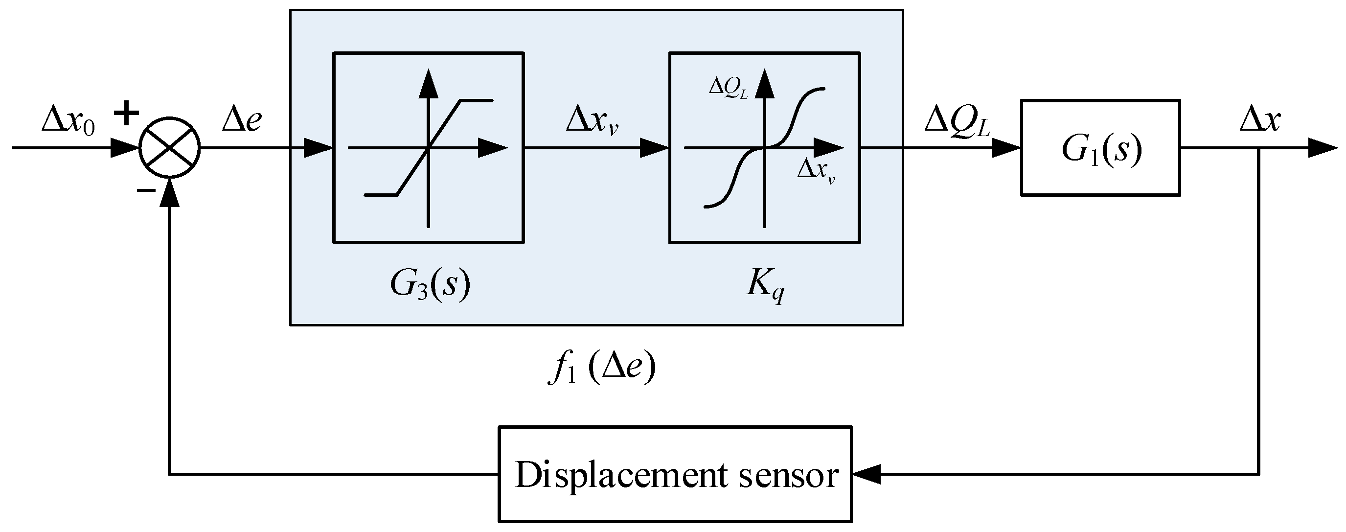
3. Incremental Transfer Model of Position Closed-Loop System

3.1. Incremental Transfer Model of Hydraulic Transmission Part

When the system is in equilibrium at the working point A, according to the mathematical model and information transfer relationship established above, the equilibrium equations of the hydraulic transmission part of the HAGC system can be derived as:
Q L A = f ( x v A , p L A ) ,
Q L A = A p x ˙ 1 A + C i p ( p L A p b ) + V 0 β e p ˙ L A ,
p L A A p p b A b = m 1 x ¨ 1 A + c 1 x ˙ 1 A + k 1 x 1 A + F L A ,
where Q L A is the value of the load flow Q L at the working point A; x v A is the value of spool displacement x v at the working point A; p L A is the value of working pressure p L at the working point A; and x 1 A is the value of piston rod displacement x 1 at the working point A.
When the system makes small disturbances near the working point A, all the variables of the system change around the equilibrium point, as follows:
Q L = Q L A + Δ Q L ,
x v = x v A + Δ x v ,
p L = p L A + Δ p L ,
x 1 = x 1 A + Δ x ,
where Δ Q L is the disturbance quantity of the load flow Q L at the working point A; Δ x v is the disturbance quantity of spool displacement x v at the working point A; Δ p L is the disturbance quantity of working pressure p L at the working point A; and Δ x is the disturbance quantity of piston rod displacement x 1 at the working point A.
The load flow of the servo valve is expanded by Taylor series near the working point A, and the high-order minor terms are omitted, so:
Q L = Q L A + Q L x v | A Δ x v + Q L p L | A Δ p L .
Then, the approximate equation of disturbance flow can be deduced when the system makes a small disturbance motion near the working point A.
Δ Q L = Q L Q L A = Q L x v | A Δ x v + Q L p L | A Δ p L = K q Δ x v K c Δ p L
where K q is the flow gain, K q = Q L x v ; and K c is the flow–pressure coefficient, K c = Q L p L .
When the system makes small disturbance motion near the working point A, the flow continuity equation of the hydraulic cylinder can be expressed as:
Q L A + Δ Q L = A p ( x ˙ 1 A + Δ x ˙ ) + C i p [ ( p L A + Δ p L ) p b ] + V 0 β e ( p ˙ L A + Δ p ˙ L ) .
In combination with Equations (12) and (20), there is:
Δ Q L = A p Δ x ˙ + C i p Δ p L + V 0 β e Δ p ˙ L .
When the system makes small disturbance motion near the working point A, the load force balance equation can be expressed as:
( p L A + Δ p L ) A p p b A b = m 1 ( x ¨ 1 A + Δ x ¨ ) + c 1 ( x ˙ 1 A + Δ x ˙ ) + k 1 ( x 1 A + Δ x ) + F L A .
In combination with Equations (13) and (22), there is:
Δ p L A p = m 1 Δ x ¨ + c 1 Δ x ˙ + k 1 Δ x .
In combination with Equations (19), (21) and (23), the incremental equations of the hydraulic transmission part can be deduced when the system makes small disturbance motion near the working point A.
{ Δ Q L = K q Δ x v K c Δ p L Δ Q L = A p Δ x ˙ + C i p Δ p L + V 0 β e Δ p ˙ L Δ p L = ( m 1 Δ x ¨ + c 1 Δ x ˙ + k 1 Δ x ) / A p
The incremental Equation (24) is further organized as follows:
K q Δ x v = V 0 m 1 β e A p Δ x + [ ( V 0 c 1 β e A p + ( C i p + K c ) m 1 A p ) ] Δ x ¨ + [ ( V 0 k 1 β e A p + ( C i p + K c ) c 1 A p + A p ) ] Δ x ˙ + ( C i p + K c ) k 1 A p Δ x
By performing Laplace transformation on Equation (25), the relationship between the load displacement disturbance Δ x and the spool displacement disturbance Δ x v can be derived.
Δ x = A p s [ V 0 m 1 β e s 2 + ( K c e m 1 + V 0 c 1 β e ) s + ( K c e c 1 + V 0 k 1 β e + A p 2 ) ] + k 1 K c e K q Δ x v
where K c e is total flow–pressure coefficient ( m 3 s 1 Pa 1 ), K c e = C i p + K c .
Suppose that:
G 1 ( s ) = A p s [ V 0 m 1 β e s 2 + ( K c e m 1 + V 0 c 1 β e ) s + ( K c e c 1 + V 0 k 1 β e + A p 2 ) ] + k 1 K c e .
In addition, according to the aforementioned theoretical formula given as Equation (3), there is:
K q = Q L x v = { C d W 2 ( p s p L ) ρ x v 0 C d W 2 ( p L p t ) ρ x v < 0 .
From Equations (26)–(28), the information transfer relationship between the displacement disturbance Δ x of the load and the displacement disturbance Δ x v of the servo valve spool can be identified, which is transmitted by the transfer function G 1 ( s ) and the nonlinear mathematical expression K q .

3.2. Incremental Transfer Model of the Feedback and Control Part

When the HAGC system adopts the position closed loop, based on the mathematical model of displacement feedback and control, the relationship between spool displacement disturbance Δ x v and load displacement disturbance Δ x can be deduced.
Δ x v = G c ( s ) K a G v ( s ) G x ( s ) Δ x = K p ( 1 + 1 T i s + T d s ) K a K x K s v ( T x s + 1 ) ( s 2 ω s v + 2 ξ s v ω s v s + 1 ) Δ x
Assume that:
G 3 ( s ) = K p ( 1 + 1 T i s + T d s ) K a K x K s v ( T x s + 1 ) ( s 2 ω s v + 2 ξ s v ω s v s + 1 ) .
It can be seen from Equations (29) and (30) that the information relationship between the spool displacement disturbance Δ x v and the load displacement disturbance Δ x is transmitted by the transfer function G 3 ( s ) . In addition, according to the input current limitation condition expression (Equation (5)) of the servo valve, it can be found that G 3 ( s ) possesses a nonlinear saturation characteristic and is a nonlinear transfer function.

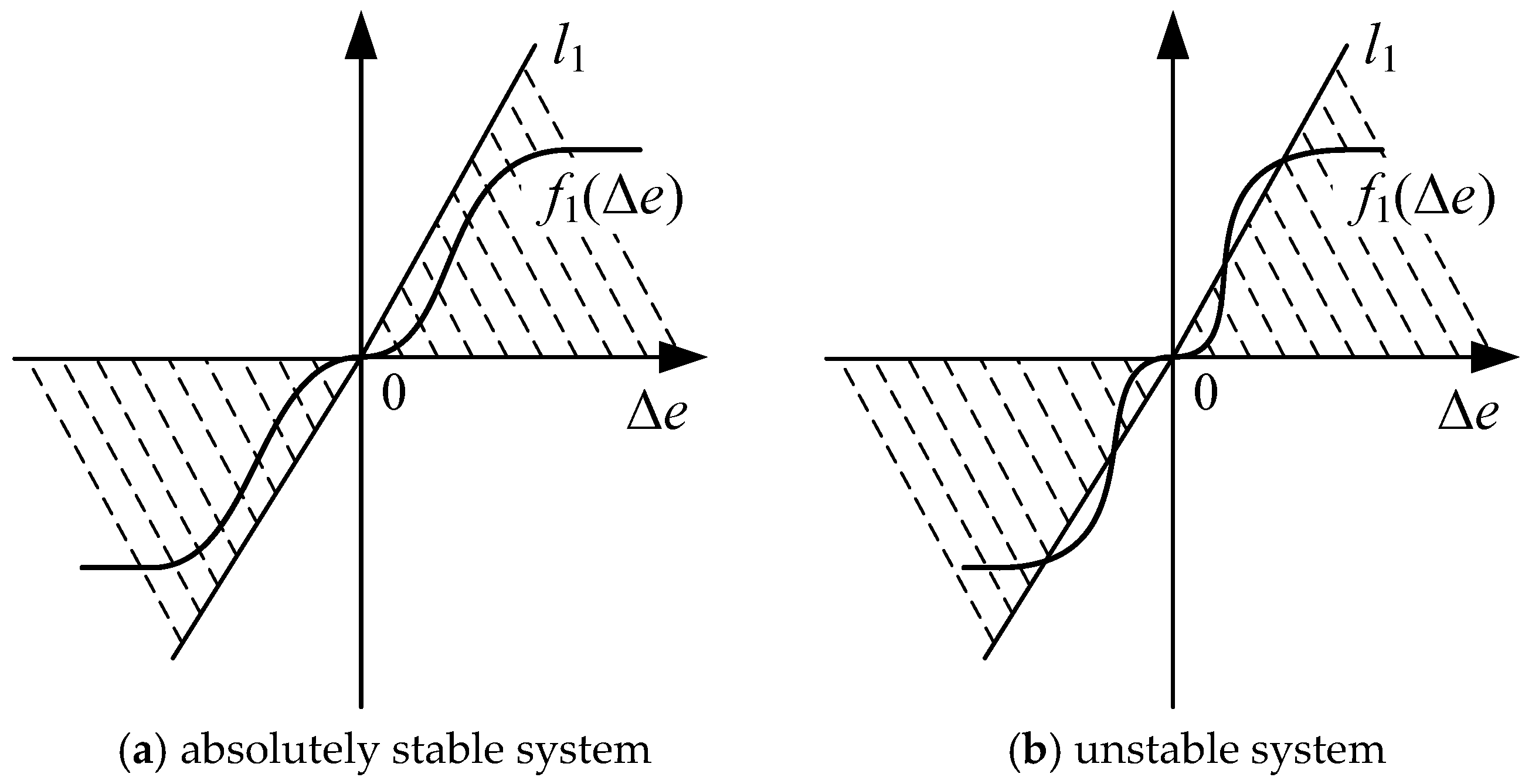
4. Absolute Stability Condition for Position Closed-Loop System

On the basis of the aforementioned derived transfer relationship, the transfer block diagram of the disturbance of the position closed-loop system is established, as shown in Figure 5. For purpose of researching the absolute stability of system, the transfer block diagram of the disturbance is the mathematical model which uses the frequency method.
In this work, the Popov frequency criterion is introduced to determine the absolute stability of the position closed-loop control of the HAGC system. For this, in the transfer function G 1 ( s ) , suppose that s = i ω , then the frequency characteristic is obtained:
G 1 ( i ω ) = Re 1 ( ω ) + i Im 1 ( ω ) .
The expression (Equation (27)) of G 1 ( s ) is substituted into Equation (31), then the real frequency and imaginary frequency characteristics can be acquired:
Re 1 ( ω ) = A p [ k 1 K c e ( K c e m 1 + V 0 c 1 β e ) ω 2 ] × { [ k 1 K c e ( K c e m 1 + V 0 c 1 β e ) ω 2 ] 2 + [ ( K c e c 1 + V 0 k 1 β e + A p 2 ) ω V 0 m 1 β e ω 3 ] 2 } 1
Im 1 ( ω ) = A p [ ( K c e c 1 + V 0 k 1 β e + A p 2 ) ω V 0 m 1 β e ω 3 ] × { [ k 1 K c e ( K c e m 1 + V 0 c 1 β e ) ω 2 ] 2 + [ ( K c e c 1 + V 0 k 1 β e + A p 2 ) ω V 0 m 1 β e ω 3 ] 2 } 1
The expression of corrected frequency characteristic G 1 * ( i ω ) is defined as:
G 1 * ( i ω ) = X 1 ( ω ) + i Y 1 ( ω ) ,
X 1 ( ω ) = Re 1 ( ω ) , Y 1 ( ω ) = ω Im 1 ( ω ) .
Then, according to Equations (32), (33) and (35), the corrected real frequency and imaginary frequency characteristics can be obtained:
X 1 ( ω ) = A p [ k 1 K c e ( K c e m 1 + V 0 c 1 β e ) ω 2 ] × { [ k 1 K c e ( K c e m 1 + V 0 c 1 β e ) ω 2 ] 2 + [ ( K c e c 1 + V 0 k 1 β e + A p 2 ) ω V 0 m 1 β e ω 3 ] 2 } 1
Y 1 ( ω ) = A p ω [ ( K c e c 1 + V 0 k 1 β e + A p 2 ) ω V 0 m 1 β e ω 3 ] × { [ k 1 K c e ( K c e m 1 + V 0 c 1 β e ) ω 2 ] 2 + [ ( K c e c 1 + V 0 k 1 β e + A p 2 ) ω V 0 m 1 β e ω 3 ] 2 } 1
The intersection between G 1 * ( i ω ) and the real axis is the critical point of the Popov frequency criterion. The coordinate is defined as ( P 1 1 , 0 ) . The abscissa value of the critical point can be obtained by using Equations (36) and (37):
X 1 ( ω * ) = A p V 0 m 1 β e β e ( K c e m 1 β e + V 0 c 1 ) ( K c e c 1 + A p 2 ) + V 0 2 k 1 c 1 .
Then by the definition of Popov line, we can know that:
P 1 = 1 X 1 ( ω * ) = β e ( K c e m 1 β e + V 0 c 1 ) ( K c e c 1 + A p 2 ) + V 0 2 k 1 c 1 A p V 0 m 1 β e .
According to Popov’s theorem [46,47], if the nonlinear characteristic function f 1 ( Δ e ) = G 3 ( s ) K q Δ e of the position closed-loop system satisfies Equation (40), the equilibrium point of the system is absolutely stable, that is:
f ( 0 ) = 0 , 0 < f 1 ( Δ e ) Δ e P 1 .
From Equation (40), it can be concluded that if the characteristic curve of the nonlinear transfer function G 3 ( s ) K q is located in the sector region, the position closed-loop system is globally asymptotically stable. The sector region is composed of the horizontal axis and the Popov line l1 which passes through the origin with a slope P1, as shown in Figure 6a. Conversely, if the characteristic curve of G 3 ( s ) K q exceeds the sector region (as illustrated in Figure 6b), the position closed-loop system is unstable. At this time, complex nonlinear dynamic behavior is likely to occur when the system parameters change.
From the above analysis, the absolute stability conditions of the position closed-loop system can be derived:
G 3 ( s ) K q β e ( K c e m 1 β e + V 0 c 1 ) ( K c e c 1 + A p 2 ) + V 0 2 k 1 c 1 A p V 0 m 1 β e .
The expression of G 3 ( s ) and K q are substituted into Equation (41), then the absolute stability condition of the position closed-loop system when the spool displacement is positive ( x v 0 ) can be obtained as:
β e ( K c e m 1 β e + V 0 c 1 ) ( K c e c 1 + A p 2 ) + V 0 2 k 1 c 1 A p V 0 m 1 β e K p ( 1 + 1 T i s + T d s ) K a K x K s v ( T x s + 1 ) ( s 2 ω s v + 2 ξ s v ω s v s + 1 ) C d W 2 ( p s p L ) ρ .
When the spool displacement is negative ( x v < 0 ) , the absolute stability condition of the position closed-loop system can be acquired as:
β e ( K c e m 1 β e + V 0 c 1 ) ( K c e c 1 + A p 2 ) + V 0 2 k 1 c 1 A p V 0 m 1 β e K p ( 1 + 1 T i s + T d s ) K a K x K s v ( T x s + 1 ) ( s 2 ω s v + 2 ξ s v ω s v s + 1 ) C d W 2 ( p L p t ) ρ .

5. Conclusions

In this paper, the function of key position closed-loop system in HAGC was introduced in detail. Based on the theoretical analysis, the mathematical model of each component was established. According to the connection relationship of each component element, the incremental transfer model of the position closed-loop system was derived. Moreover, according to the derived information transfer relationship, the transfer block diagram of the disturbance of the system was established. Furthermore, the Popov frequency criterion method was introduced to derive the absolute stability condition. The absolute stability conditions of the system are acquired in the following two conditions: when the spool displacement of the servo valve is positive or negative.
The obtained results lay a theoretical foundation for the study of the instability mechanism of the HAGC system. This research can provide a significant basis for the further investigation on the vibration traceability and control of the HAGC system.

Author Contributions

Conceptualization, Y.Z. and W.J.; Methodology, S.T.; Investigation, Y.Z. and S.T.; Writing-Original Draft Preparation, Y.Z.; Writing-Review & Editing, J.Z. and G.L.; Supervision, C.W.

Funding

This research was funded by National Natural Science Foundation of China (No. 51805214, 51875498), China Postdoctoral Science Foundation (No. 2019M651722), Natural Science Foundation of Hebei Province (No. E2018203339), Nature Science Foundation for Excellent Young Scholars of Jiangsu Province (No. BK20190101), Open Foundation of National Research Center of Pumps, Jiangsu University (No. NRCP201604) and Open Foundation of the State Key Laboratory of Fluid Power and Mechatronic Systems (No. GZKF-201714).

Conflicts of Interest

The authors declare no conflict of interest.

Nomenclature

HAGChydraulic automatic gauge control
PIDProportion-integration-differentiation
DOFdegree of freedom
Kpproportionality coefficient
Tiintegral time constant
Tddifferential time constant
sLaplace operator
Ioutput current
Uinput voltage
Kaamplification coefficient
QLload flow
xvspool displacement
Cdflow coefficient of valve port
Warea gradient of valve port
ρhydraulic oil density
psoil supply pressure
ptreturn pressure
pLworking pressure of rodless chamber of hydraulic cylinder
Icinput current of servo valve
Ksvamplification coefficient of the spool displacement on the input current
ωsvnatural angular frequency of servo valve
ξsvdamping coefficient of servo valve
INrated current of servo valve
Apeffective working area of piston
x1displacement of piston rod
Cipinternal leakage coefficient
Cepexternal leakage coefficient
pbworking pressure of the rod chamber
V0initial volume of the control chamber
βebulk modulus of oil
m1equivalent mass of moving parts of the upper roll system (URS)
m2equivalent mass of the moving parts of the lower roll system (LRS)
c1linear damping coefficient of moving parts of URS
c2linear damping coefficient of moving parts of LRS
k1linear stiffness coefficient between upper frame beam and moving parts of URS
k2linear stiffness coefficient between lower frame beam and moving parts of LRS
x1displacement of URS
x2displacement of LRS
Abeffective working area of rod chamber piston
FLload force acting on roll system
Kxamplification coefficient of the displacement sensor
Txtime constant of the displacement sensor
QLAthe value of load flow at the working point A
xvAthe value of spool displacement at the working point A
pLAthe value of working pressure at the working point A
x1Athe value of piston rod displacement at the working point A
ΔQLdisturbance quantity of load flow at the working point A
Δxvdisturbance quantity of spool displacement at the working point A
ΔpLdisturbance quantity of working pressure at the working point A
Δxdisturbance quantity of piston rod displacement at the working point A
Kqflow gain
Kcflow–pressure coefficient
Kcetotal flow–pressure coefficient

References

  1. Tang, S.N.; Zhu, Y.; Li, W.; Cai, J.X. Status and prospect of research in preprocessing methods for measured signals in mechanical systems. J. Drain. Irrig. Mach. Eng. 2019, 37, 822–828. [Google Scholar]
  2. Tang, B.; Jiang, H.; Gong, X. Optimal design of variable assist characteristics of electronically controlled hydraulic power steering system based on simulated annealing particle swarm optimisation algorithm. Int. J. Veh. Des. 2017, 73, 189–207. [Google Scholar] [CrossRef]
  3. He, R.; Liu, X.; Liu, C. Brake performance analysis of ABS for eddy current and electrohydraulic hybrid brake system. Math. Probl. Eng. 2013, 2013, 979384. [Google Scholar] [CrossRef]
  4. Yu, Y.; Zhang, C.; Han, X.J.; Bi, Q.S. Dynamical behavior analysis and bifurcation mechanism of a new 3- D nonlinear periodic switching system. Nonlinear Dyn. 2013, 73, 1873–1881. [Google Scholar] [CrossRef]
  5. Roman, N.; Ceanga, E.; Bivol, I.; Caraman, S. Adaptive automatic gauge control of a cold strip rolling process. Adv. Electr. Comput. Eng. 2010, 10, 7–17. [Google Scholar] [CrossRef]
  6. Hu, Y.J.; Sun, J.; Wang, Q.L.; Yin, F.C.; Zhang, D.H. Characteristic analysis and optimal control of the thickness and tension system on tandem cold rolling. Int. J. Adv. Manuf. Technol. 2019, 101, 2297–2312. [Google Scholar] [CrossRef]
  7. Sun, J.L.; Peng, Y.; Liu, H.M. Dynamic characteristics of cold rolling mill and strip based on flatness and thickness control in rolling process. J. Cent. South Univ. 2014, 21, 567–576. [Google Scholar] [CrossRef]
  8. Prinz, K.; Steinboeck, A.; Muller, M.; Ettl, A.; Kugi, A. Automatic gauge control under laterally asymmetric rolling conditions combined with feedforward. IEEE Trans. Ind. Appl. 2017, 53, 2560–2568. [Google Scholar] [CrossRef]
  9. Prinz, K.; Steinboeck, A.; Kugi, A. Optimization-based feedforward control of the strip thickness profile in hot strip rolling. J. Process Control 2018, 64, 100–111. [Google Scholar] [CrossRef]
  10. Kovari, A. Influence of internal leakage in hydraulic capsules on dynamic behavior of hydraulic gap control system. Mater. Sci. Forum 2015, 812, 119–124. [Google Scholar] [CrossRef]
  11. Li, J.X.; Fang, Y.M.; Shi, S.L. Robust output-feedback control for hydraulic servo-position system of cold-strip rolling mill. Control Theory Appl. 2012, 29, 331–336. [Google Scholar]
  12. Sun, W.Q.; Shao, J.; Song, Y.; Guan, J.L. Research and development of automatic control system for high precision cold strip rolling mill. Adv. Mater. Res. 2014, 952, 283–286. [Google Scholar] [CrossRef]
  13. Yi, J.G. Modelling and analysis of step response test for hydraulic automatic gauge control. J. Mech. Eng. 2015, 61, 115–122. [Google Scholar] [CrossRef]
  14. Liu, H.S.; Zhang, J.; Mi, K.F.; Gao, J.X. Simulation on hydraulic-mechanical coupling vibration of cold strip rolling mill vertical system. Adv. Mater. Res. 2013, 694, 407–414. [Google Scholar] [CrossRef]
  15. Wang, J.; Sun, B.; Huang, Q.; Li, H. Research on the position-pressure master-slave control for rolling shear hydraulic servo system. Stroj. Vestn. 2015, 61, 265–272. [Google Scholar]
  16. Hua, C.C.; Yu, C.X. Controller design for cold rolling mill HAGC system with measurement delay perturbation. J. Mech. Eng. 2014, 50, 46–53. [Google Scholar] [CrossRef]
  17. Zhang, B.; Wei, W.; Qian, P.; Jiang, Z.; Li, J.; Han, J.; Mujtaba, M. Research on the control strategy of hydraulic shaking table based on the structural flexibility. IEEE Access 2019, 7, 43063–43075. [Google Scholar] [CrossRef]
  18. Wang, C.; Hu, B.; Zhu, Y.; Wang, X.; Luo, C.; Cheng, L. Numerical study on the gas-water two-phase flow in the self-priming process of self-priming centrifugal pump. Processes 2019, 7, 330. [Google Scholar] [CrossRef]
  19. Wang, C.; Shi, W.; Wang, X.; Jiang, X.; Yang, Y.; Li, W.; Zhou, L. Optimal design of multistage centrifugal pump based on the combined energy loss model and computational fluid dynamics. Appl. Energy 2017, 187, 10–26. [Google Scholar] [CrossRef]
  20. Qian, J.Y.; Gao, Z.X.; Liu, B.Z.; Jin, Z.J. Parametric study on fluid dynamics of pilot-control angle globe valve. ASME J. Fluids Eng. 2018, 140, 111103. [Google Scholar] [CrossRef]
  21. Qian, J.Y.; Chen, M.R.; Liu, X.L.; Jin, Z.J. A numerical investigation of the flow of nanofluids through a micro Tesla valve. J. Zhejiang Univ. Sci. A 2019, 20, 50–60. [Google Scholar] [CrossRef]
  22. Hou, C.W.; Qian, J.Y.; Chen, F.Q.; Jiang, W.K.; Jin, Z.J. Parametric analysis on throttling components of multi-stage high pressure reducing valve. Appl. Therm. Eng. 2018, 128, 1238–1248. [Google Scholar] [CrossRef]
  23. Wang, C.; He, X.; Zhang, D.; Hu, B.; Shi, W. Numerical and experimental study of the self-priming process of a multistage self-priming centrifugal pump. Int. J. Energy Res. 2019, 43, 4074–4092. [Google Scholar] [CrossRef]
  24. Wang, C.; He, X.; Shi, W.; Wang, X.; Wang, X.; Qiu, N. Numerical study on pressure fluctuation of a multistage centrifugal pump based on whole flow field. AIP Adv. 2019, 9, 035118. [Google Scholar] [CrossRef] [Green Version]
  25. He, X.; Jiao, W.; Wang, C.; Cao, W. Influence of surface roughness on the pump performance based on Computational Fluid Dynamics. IEEE Access 2019, 7, 105331–105341. [Google Scholar] [CrossRef]
  26. Wang, C.; Chen, X.X.; Qiu, N.; Zhu, Y.; Shi, W.D. Numerical and experimental study on the pressure fluctuation, vibration, and noise of multistage pump with radial diffuser. J. Braz. Soc. Mech. Sci. Eng. 2018, 40, 481. [Google Scholar] [CrossRef]
  27. Hu, B.; Li, X.; Fu, Y.; Zhang, F.; Gu, C.; Ren, X.; Wang, C. Experimental investigation on the flow and flow-rotor heat transfer in a rotor-stator spinning disk reactor. Appl. Therm. Eng. 2019, 162, 114316. [Google Scholar] [CrossRef]
  28. Ye, S.G.; Zhang, J.H.; Xu, B.; Zhu, S.Q. Theoretical investigation of the contributions of the excitation forces to the vibration of an axial piston pump. Mech. Syst. Signal Process. 2019, 129, 201–217. [Google Scholar] [CrossRef]
  29. Zhang, J.H.; Xia, S.; Ye, S.; Xu, B.; Song, W.; Zhu, S.; Xiang, J. Experimental investigation on the noise reduction of an axial piston pump using free-layer damping material treatment. Appl. Acoust. 2018, 139, 1–7. [Google Scholar] [CrossRef]
  30. Bai, L.; Zhou, L.; Jiang, X.P.; Pang, Q.L.; Ye, D.X. Vibration in a multistage centrifugal pump under varied conditions. Shock Vib. 2019, 2019, 2057031. [Google Scholar] [CrossRef]
  31. Bai, L.; Zhou, L.; Han, C.; Zhu, Y.; Shi, W.D. Numerical study of pressure fluctuation and unsteady flow in a centrifugal pump. Processes 2019, 7, 354. [Google Scholar] [CrossRef]
  32. Wang, L.; Liu, H.L.; Wang, K.; Zhou, L.; Jiang, X.P.; Li, Y. Numerical simulation of the sound field of a five-stage centrifugal pump with different turbulence models. Water 2019, 11, 1777. [Google Scholar] [CrossRef]
  33. Ding, S.; Zheng, W.X. Controller design for nonlinear affine systems by control Lyapunov functions. Syst. Control Lett. 2013, 62, 930–936. [Google Scholar] [CrossRef]
  34. Liu, L.; Ding, S.H.; Ma, L.; Sun, H.B. A novel second-order sliding mode control based on the Lyapunov method. Trans. Inst. Meas. Control 2018, 41, 014233121878324. [Google Scholar] [CrossRef]
  35. Zhang, J. Integral barrier Lyapunov functions-based neural control for strict-feedback nonlinear systems with multi-constraint. Int. J. Control Autom. Syst. 2018, 16, 2002–2010. [Google Scholar] [CrossRef]
  36. Zhang, J.; Li, G.S.; Li, Y.H.; Dai, X.K. Barrier Lyapunov functions-based localized adaptive neural control for nonlinear systems with state and asymmetric control constraints. Trans. Inst. Meas. Control 2019, 41, 1656–1664. [Google Scholar] [CrossRef]
  37. Yang, C.; Zhang, Q.; Zhou, L. Strongly absolute stability of Lur’e descriptor systems: Popov-type criteria. Int. J. Robust Nonlinear Control 2009, 19, 786–806. [Google Scholar] [CrossRef]
  38. Saeki, M.; Wada, N.; Satoh, S. Stability analysis of feedback systems with dead-zone nonlinearities by circle and Popov criteria. Automatica 2016, 66, 96–100. [Google Scholar] [CrossRef]
  39. Xia, L.; Jiang, H. An electronically controlled hydraulic power steering system for heavy vehicles. Adv. Mech. Eng. 2016, 8, 1687814016679566. [Google Scholar] [CrossRef]
  40. Zhang, R.; Wang, Y.; Zhang, Z.D.; Bi, Q.S. Nonlinear behaviors as well as the bifurcation mechanism in switched dynamical systems. Nonlinear Dyn. 2015, 79, 465–471. [Google Scholar] [CrossRef]
  41. Bi, Q.S.; Li, S.L.; Kurths, J.; Zhang, Z.D. The mechanism of bursting oscillations with different codimensional bifurcations and nonlinear structures. Nonlinear Dyn. 2016, 85, 993–1005. [Google Scholar] [CrossRef]
  42. Xue, Z.H.; Cao, X.; Wang, T.Z. Vibration test and analysis on the centrifugal pump. J. Drain. Irrig. Mach. Eng. 2018, 36, 472–477. [Google Scholar]
  43. Zhu, Y.; Tang, S.N.; Quan, L.X.; Jiang, W.L.; Zhou, L. Extraction method for signal effective component based on extreme-point symmetric mode decomposition and Kullback-Leibler divergence. J. Braz. Soc. Mech. Sci. Eng. 2019, 41, 100. [Google Scholar] [CrossRef]
  44. Zhu, Y.; Qian, P.F.; Tang, S.N.; Jiang, W.L.; Li, W.; Zhao, J.H. Amplitude-frequency characteristics analysis for vertical vibration of hydraulic AGC system under nonlinear action. AIP Adv. 2019, 9, 035019. [Google Scholar] [CrossRef] [Green Version]
  45. Zhu, Y.; Tang, S.; Wang, C.; Jiang, W.; Yuan, X.; Lei, Y. Bifurcation characteristic research on the load vertical vibration of a hydraulic automatic gauge control system. Processes 2019, 7, 718. [Google Scholar] [CrossRef]
  46. Liu, Y.Z.; Chen, L.Q. Nonlinear Vibration; Higher Education Press: Beijing, China, 2001; pp. 57–123. [Google Scholar]
  47. Ding, W.J. Self-Excited Vibration; Tsinghua University Press: Beijing, China, 2009; Volume 84, pp. 238–242. [Google Scholar]
Figure 1. Function diagram of the hydraulic automatic gauge control (HAGC) system.
Processes 07 00766 g001
Figure 2. Schematic diagram of the servo valve control hydraulic cylinder.
Processes 07 00766 g002
Figure 3. Structure diagram of four-high load roll system.
Processes 07 00766 g003
Figure 4. Two degrees of freedom mechanics model of the load roll system.
Processes 07 00766 g004
Figure 5. Transfer block diagram of the disturbance of the position closed-loop system.
Processes 07 00766 g005
Figure 6. Relation between the nonlinear characteristic curve of the position closed-loop system and l1.
Processes 07 00766 g006

