1. Introduction
With the year-by-year increase in the mining depth of coal mines in China, the problem of surrounding rock stability of composite roadway roofs has become a key bottleneck restricting the safe and efficient exploitation of deep resources [
1,
2,
3]. Composite roofs are usually formed by the alternating superposition of rock strata with significant differences in mechanical properties, and their inhomogeneity, weak interface effect and coupling effect of dynamic mining-induced stress render the roadway roofs prone to delamination, flexural fracture and sudden roof collapse accidents [
4], which seriously endangers the safe production of coal mines.
Aiming at the flexural deformation and failure of composite roofs, scholars have commonly conducted three-point or four-point bending tests to investigate the mechanical properties of composite rock mass during the process of flexural deformation and failure. Wang et al. [
5] carried out three-point bending tests on limestone with precast fissures and analyzed the evolution laws of strain field and fractures during flexural deformation by means of digital speckle correlation monitoring. Ren et al. [
6] combined three-point bending tests with fractal dimension analysis to quantify the influence of fracture surface roughness on composite fracture strength and verified the applicability of fractal theory in cross-scale damage characterization. Zhang et al. [
7] performed three-point bending tests on coal–rock composites and revealed the effect of strength on the fracture surface characteristics of layered composite rock mass under flexural failure. Song [
8] prepared composite cuboid specimens to conduct three-point bending tests, systematically studied the influences of rock strength and thickness on fracture surfaces, and unveiled the crack development laws of layered composite rock mass during flexural failure. Zhao et al. [
9] carried out three-point bending tests on rock samples to determine the influence of precast fissures on the peak load of rock mass and elaborated the calculation formula for the flexural strength of three-point bending beams. Xu et al. [
10,
11] fabricated layered composite rock mass specimens with fine sandstone and conducted three-point bending tests, analyzing the interface mechanical characteristics throughout the entire deformation and failure process as well as the effects of interlayer contact on peak load and maximum displacement. Song et al. [
12] selected layered composite rock mass with two types of interface forms to perform four-point bending tests and investigated the deformation and energy evolution of layered rock mass.
Regarding the fracture evolution process of composite rock masses, scholars at home and abroad have revealed the influences of various factors on the fracture evolution of layered composite rock masses through laboratory tests. Huang et al. [
13] conducted laboratory tests on soft–hard interbedded rock masses and obtained the quantitative relationship between the thickness of the soft layer and fracture propagation. Teng et al. [
14] investigated the damage and fracture process as well as acoustic emission (AE) characteristics of layered composite rock masses under uniaxial compression and identified the crack development law using CT scanning. Nian et al. [
15] carried out numerical simulations on composite rock masses with weak interlayers and found that microcracks mainly initiate at the interfaces and loading plate areas. Zhong et al. [
16] analyzed the entire process of fracture development based on fracture mechanics and studied the effects of joint fractures on the fracture characteristics of layered composite rock masses. Wang et al. [
17] analyzed the influences of different confining pressures and dip angles on fracture development and evolution from the perspective of the mechanical behavior of composite assemblage materials. Jian et al. [
18] elaborated on three types of fracture failure and the fracture development process by using the statistical theory of continuous damage mechanics and derived a rock damage constitutive model under triaxial compression conditions. Lin et al. [
19] performed uniaxial compression tests on jointed soft–hard composite rock masses, and analyzed the effects of joint angle, ligament angle and out-of-plane joint position on the crack propagation behavior of specimens through the b-value, AE counts and cumulative ringing counts. Li et al. [
20] conducted uniaxial cyclic compression tests on composite coal–rock specimens, constructed a damage variable evolution model by combining dissipated energy and AE parameters, and revealed the dominant role of coal–rock interface slip in overall instability. Dong et al. [
21] studied the re-crushing characteristics of coal–sandstone composite broken masses under dynamic loading and found through fractal dimension analysis that the cumulative AE counts of composite rock masses fall between those of single-lithology rock masses, and the energy release exhibits a multi-peak characteristic, which reflects the phased failure of different components. Liu et al. [
22] revealed the nonlinear damage evolution of composite roof rock masses under different stress paths through multifractal analysis and found that AE parameters are correlated with the dynamic changes of the fractal spectrum.
In summary, existing studies still have three core limitations: (1) The three-point bending test cannot eliminate the shear stress interference induced by concentrated loads, making it difficult to reproduce the real stress state of the pure bending section of the roadway roof, which leads to a deviation between the test results and on-site engineering practice. (2) Existing studies mostly focus on the influence of a single factor on the strength of homogeneous or composite rock masses, and there is insufficient systematic research on the interface effect, crack type transformation mechanism, and damage evolution law of flexural failure of layered composite rock masses under the coupling of multiple factors, including lithological combination, loading rate, and span. (3) Existing studies have failed to clarify the main controlling factors of the flexural failure of composite roofs, and it is difficult to establish a direct correlation between test results and on-site support design, resulting in insufficient engineering guidance.
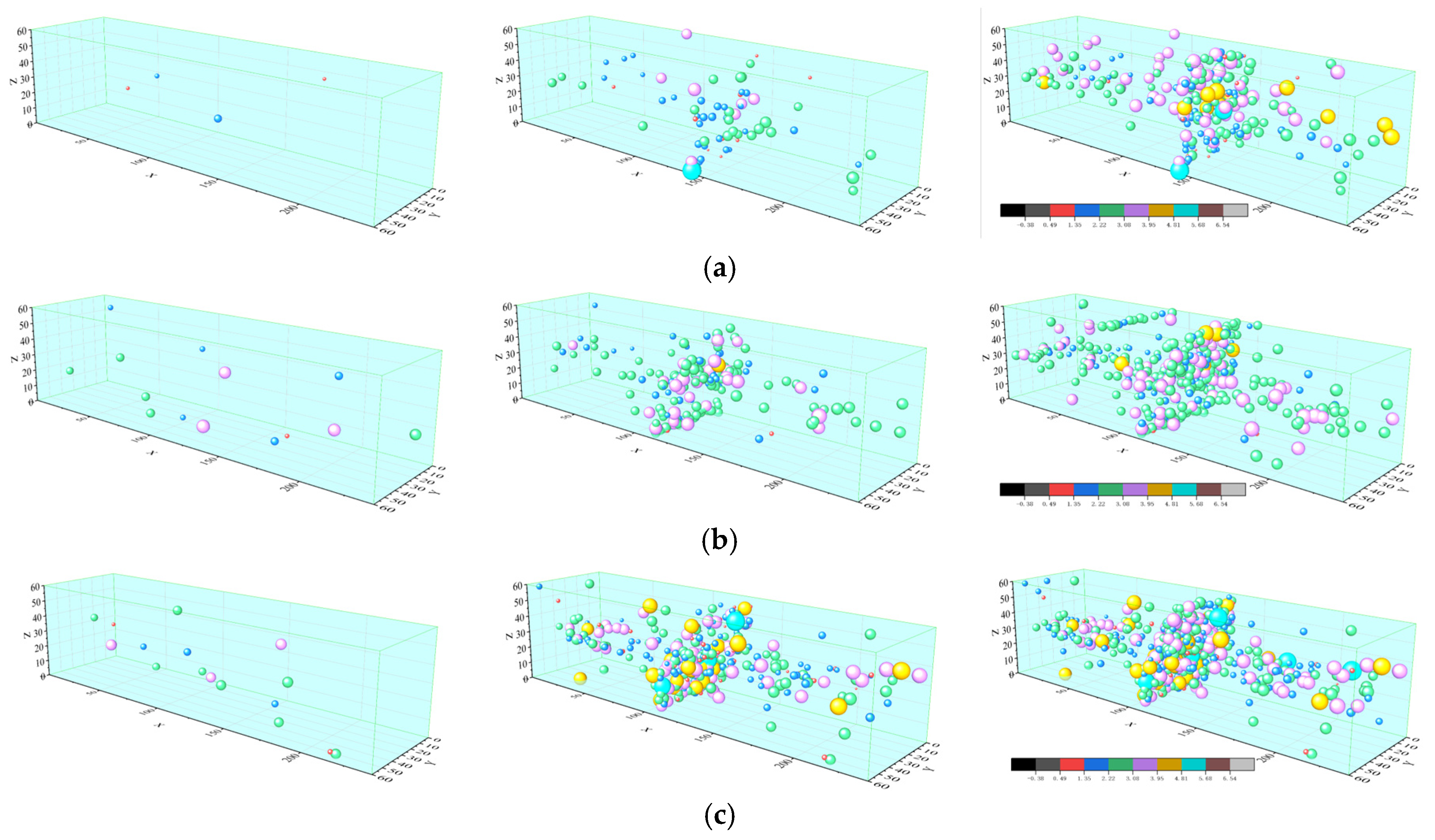
On this basis, this paper takes the composite roof of the No. 4 working face in the West No. 1 Mining Area of Shuangyang Coal Mine in Shuangyashan as the research object. Soft-hard interbedded specimens composed of fine sandstone and tuff are prepared to carry out four-point bending tests so as to eliminate the interference of shear stress and reproduce the real bending stress state of the roadway roof. The effects of lithological combination, loading rate and span on the flexural mechanical properties and deformation modes of the composite rock mass are systematically investigated. Combined with strain monitoring and acoustic emission (AE) localization technology, the fracture evolution law and mesoscopic mechanism of the composite rock mass during the whole process of flexural failure are revealed. Finally, the core innovations and engineering application value of this study are clarified, which can provide theoretical support for the support design and hazard prevention and control of deep coal mine roadways with composite roofs.
2. Test Scheme for Four-Point Bending of Layered Composite Rock Mass
2.1. Test Design Concept
This study takes the composite roof of the No. 4 working face in the West No. 1 Mining Area of Shuangyang Coal Mine in Shuangyashan as the engineering prototype. The roof of this working face features a typical structure of alternating fine sandstone (hard rock) and tuff (soft rock) layers, whose occurrence characteristics are highly consistent with those of composite roofs in deep roadways of coal mines in northeast China. Specifically, the fine sandstone is dominated by 65–75% quartz and 15–20% feldspar, presenting a medium-fine-grained structure with a grain size of 0.1–0.5 mm, cemented by siliceous + calcareous materials with moderate cementation degree. The tuff is mainly composed of 50–60% volcanic glass and 20–25% plagioclase, exhibiting a silty structure with a grain size of <0.05 mm, cemented by volcanic ash with weak cementation degree. The fine sandstone and tuff cores used in the tests were all collected from the on-site roof strata of the aforementioned working face to ensure consistency between the test materials and engineering practice. Meanwhile, these two rock types were selected as typical representatives of hard and soft rock layers, and their strength difference was utilized to reflect the common roof lithological combination characteristics of coal mines in north China. The specimens were bonded by marble adhesive under pressure to ensure interlayer bonding strength, thereby simulating the natural cementation state of rock strata.
Under deep mining conditions, the roadway roof is subjected to bending moments at both ends under the following working conditions: ① After roadway excavation, the redistribution of the in situ stress field causes the roof strata to form a cantilever beam effect due to self-weight and overlying strata load, with the coal–rock masses at both ribs serving as fixed supports to bear the bending moment. ② Under the influence of mining activities, the advance abutment pressure of the working face is transmitted to the roadway roof, resulting in a flexural stress state where the middle of the roof is in tension and both ends are in compression. ③ The layered roof undergoes delamination deformation due to lithological differences, and the differential displacement at the interface between hard and soft rock layers induces additional bending moments.
Cracks generated by rock mass failure under loading are classified into Mode I (tensile) cracks and Mode II (shear) cracks based on fracture mechanics characteristics: Mode I cracks are dominated by tensile stress, with crack surfaces perpendicular to the tensile stress direction, and rock masses on both sides of the crack undergo normal separation. Visually, the crack surfaces are relatively flat, and the fractures show vertical penetration without obvious rock dislocation traces. Mode II cracks are dominated by shear stress, with crack surfaces parallel to the shear stress direction, and rock masses on both sides of the crack undergo tangential relative slip. Visually, the crack surfaces are rough, and the fractures show inclined propagation, accompanied by obvious interlayer dislocation and friction traces.
The four-point bending test simulates the above working conditions through fixed support boundary conditions at both ribs. The pure bending zone generated by this test is highly consistent with the stress state in the maximum bending zone of the roof. Compared with the three-point bending test, the four-point bending test eliminates the interference of shear stress and can accurately capture the flexural failure process dominated by Mode I tensile cracks.
The test span was determined based on the geometric similarity criterion: taking the actual span of the on-site roadway (3.4–3.8 m) as the prototype, the test span was set to 170–190 mm according to a similarity ratio of 1:20. The specimen size and span/height ratio were designed in accordance with the ISRM rock bending test standards and the Standard for Engineering Rock Mass Test Methods (GB/T 50266-2013) [
23]. The loading rate was set to 0.002–0.02 mm/s by referring to rock mechanics test specifications and on-site excavation disturbance rates, so as to simulate the disturbance effect of different underground excavation speeds on the roof. A combined internal and external monitoring method was established: high-speed cameras and strain gauges were used to monitor the deformation trends and fracture development on the specimen surface, while acoustic emission (AE) monitoring was adopted to track the internal fracture evolution process of the specimens. These multiple monitoring methods were jointly applied to explore the flexural failure characteristics and fracture evolution laws of the layered composite rock mass.
2.2. Test System
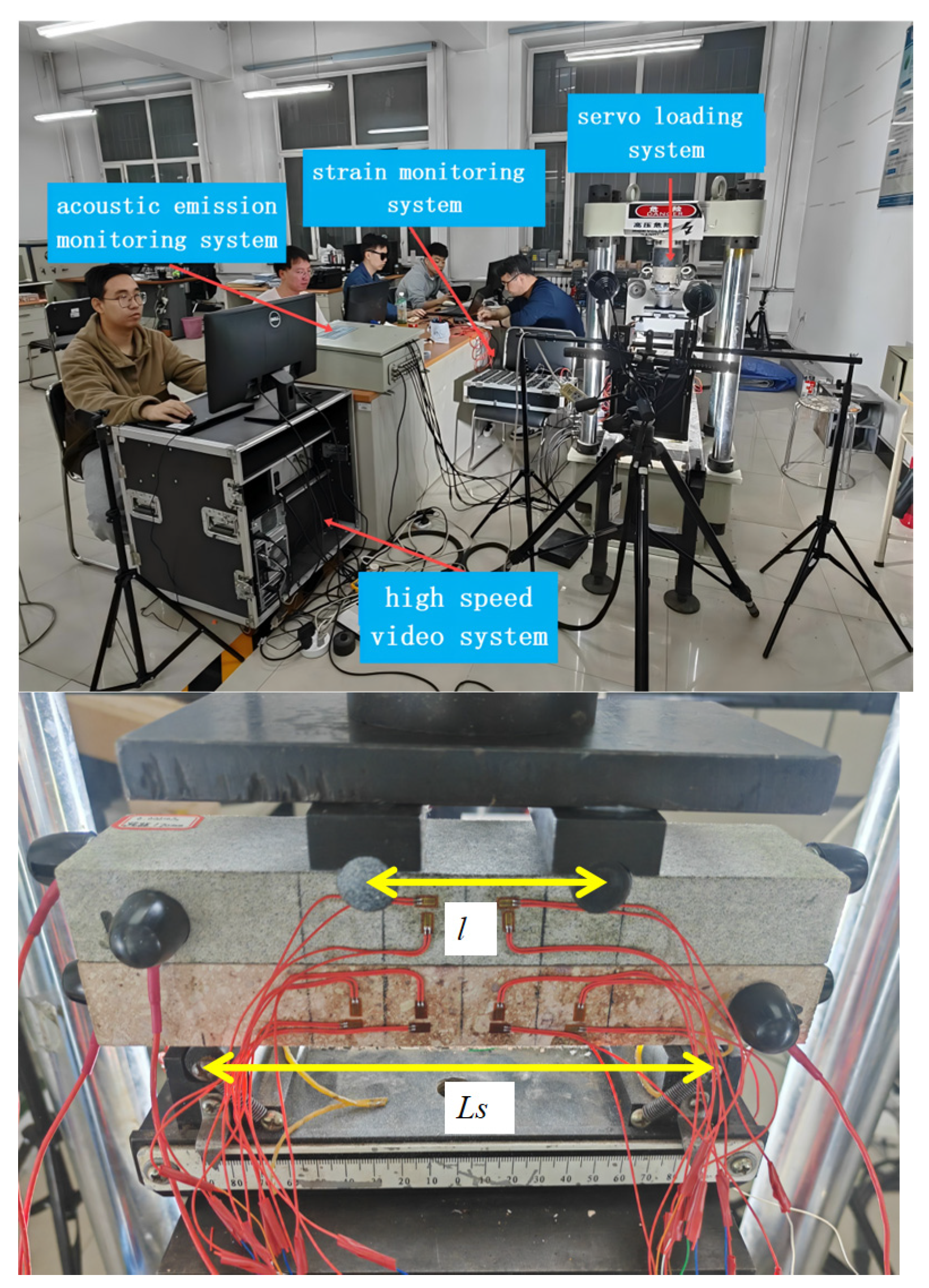
In this experiment, the TYJ-500kN servo-controlled rock testing system (Changchun, China) equipped with four-point bending steel fixtures was adopted to conduct the four-point bending mechanical tests. An SH-II acoustic emission (AE) system (Princeton, NJ, USA), uT7160 static strain gauge (Suzhou, China) and SONY high-definition digital camera (Tokyo, Japan) were used for real-time data acquisition and monitoring, as shown in
Figure 1.
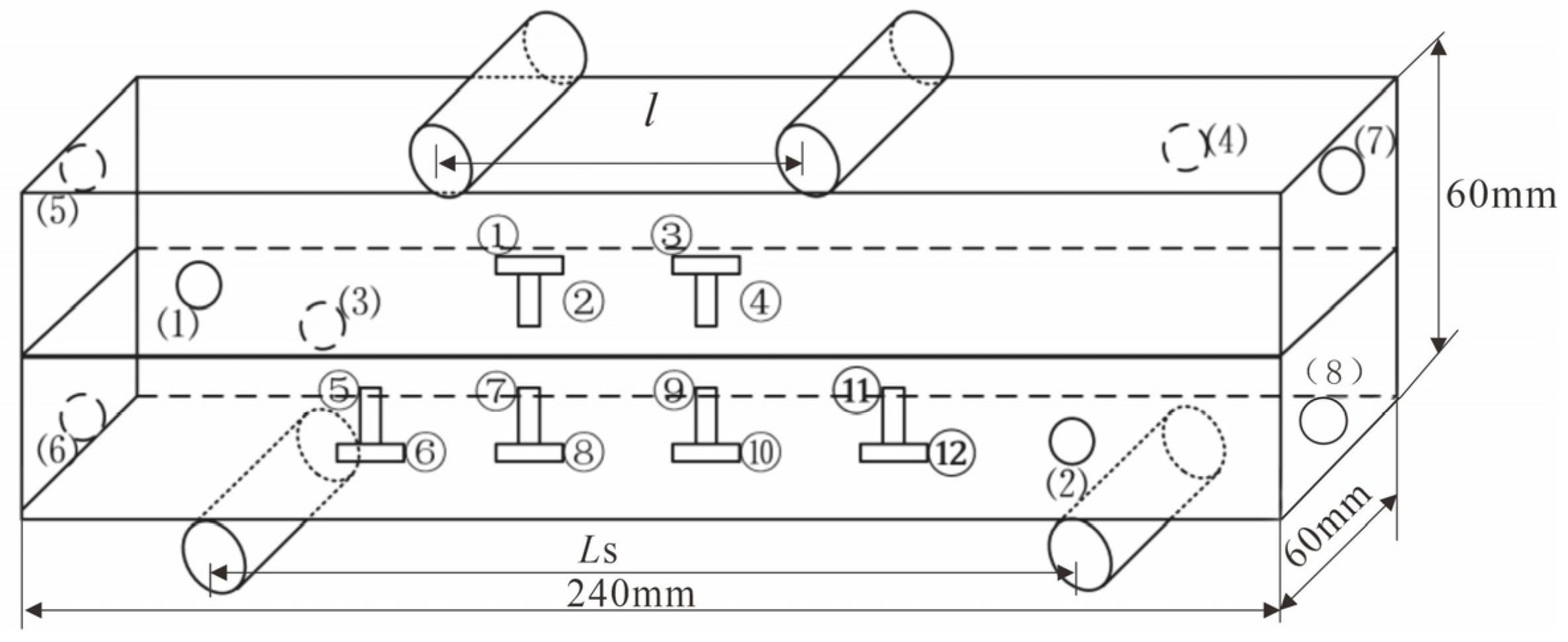
During the test, the acoustic emission (AE) monitoring system was set with a sampling frequency of 1 MHz, a threshold value of 40 dB, and a preamplifier gain of 40 dB. Eight probes were symmetrically arranged on the front and rear surfaces of the specimen to achieve accurate full-space localization of AE events. Strain gauges were symmetrically bonded to the mid-span section along the height direction of the specimen to monitor the distribution and evolution of tensile and compressive strains during the bending process. The high-speed camera was set at a frame rate of 200 fps to record the entire process of crack initiation, propagation, and penetration on the specimen surface. The specific bonding positions of the AE probes and strain gauges, as well as the key dimensions of the specimen, are as follows: total length of 240 mm, cross-section of 60 mm × 60 mm, test spans of 170/180/190 mm, and loading point spacing of 60 mm. The strain gauges are symmetrically arranged along the height direction of the mid-span section, and the AE probes are symmetrically distributed on the front and rear surfaces of the specimen, as shown in
Figure 2.
2.3. Test Scheme for Four-Point Bending of Layered Composite Rock Mass
2.3.1. Specimen Preparation
The fine sandstone and tuff used for specimen preparation were both obtained from intact rock cores of the roof of the No. 4 working face in the West No. 1 Mining Area of Shuangyang Coal Mine and processed in accordance with the Specifications for Rock Mechanics Tests and ISRM (International Society for Rock Mechanics) recommended standards. Single-lithology specimens: Dimensions are 240 mm × 60 mm × 60 mm.
Layered composite specimens: Adopt a binary superimposed structure with fine sandstone as the upper layer and tuff as the lower layer. Each single rock layer has dimensions of 240 mm × 60 mm × 30 mm, and the overall dimensions after superimposition are consistent with those of single-lithology specimens to ensure the span/height ratio of the specimens meets the requirements of bending tests. Epoxy marble adhesive for stone materials was used for interlayer bonding. Through standardized tests, the mechanical properties of this adhesive are as follows: compressive strength of 85 MPa, tensile strength of 12 MPa, and elastic modulus of 38 GPa. These parameters are highly matched with those of fine sandstone, which can avoid the bonding layer becoming a controlling weak plane affecting the mechanical properties of the specimens. The bonding process is detailed as follows: ① Precision grinding was performed on the bonding surfaces of the rock layers to ensure a flatness error ≤ 0.02 mm, and surface dust was cleaned with anhydrous ethanol. ② A 0.3 mm thick layer of marble adhesive was uniformly applied on the bonding surfaces. After accurately aligning the two rock layers, a constant pressure of 0.5 MPa was applied, followed by curing at room temperature for 72 h. ③ After curing, non-destructive testing was conducted on the specimens using an ultrasonic detector to eliminate specimens with bonding surface defects, ensuring interlayer bonding quality and simulating the natural cementation state of rock strata.
2.3.2. Test Scheme
Three groups of variables were set in this test, namely, lithological combination, loading rate, and span. Each group included 3 parallel specimens, and the average value was taken as the final result to eliminate the influence of specimen discreteness. Based on the different variables in the four-point bending test, the specimens, with varying lithologies, loading rates, and spans were coded as “A”, “B”, and “C” respectively, with the corresponding variable conditions indicated thereafter. Thus, the designations of the specimens for the four-point bending test under different variable conditions are as follows: A-S-1~A-S-3, A-T-1~A-T-3, A-ST-1~A-ST-3, B-0.001-1~B-0.001-3, B-0.02-1~B-0.02-3, C-170-1~C-170-3, and C-180-1~C-180-3.
All tests were performed using a displacement-controlled loading method, and four-point bending tests were conducted on layered composite rock masses under the conditions of different lithologies, different loading rates and different spans. The A group of tests comprised four-point bending tests on rock specimens with different lithologies, with lithology as the variable (i.e., pure fine sandstone, layered composite rock mass and pure tuff). The displacement loading rate was set at 0.002 mm/s, and loading was continued until the specimens lost their bearing capacity. The B group consisted of four-point bending tests on layered composite rock masses with different loading rates, where layered composite rock masses were used as the test specimens and displacement loading rate was the variable (0.002 mm/s, 0.01 mm/s and 0.02 mm/s), with loading applied until the specimens lost their bearing capacity. The C group consisted of four-point bending tests on layered composite rock masses with different spans, in which layered composite rock masses served as the test specimens and span was the variable. The spacing of the upper loading indenters was fixed at 60 mm, with the test span
set at 190 mm, 180 mm and 170 mm, respectively. The displacement loading rate was set at 0.002 mm/s, and loading was performed until the specimens lost their bearing capacity. In addition,
b denotes the cross-sectional width and
h represents the rock mass thickness of the specimens, with all specimen variables detailed in
Table 1.
4. Crack Development Analysis of Layered Composite Rock Mass
4.1. Statistical Analysis of Crack Types in Layered Sandstone Based on Experimental Observations
Based on fracture mechanics theory and experimental image monitoring results, the classification and judgment criteria of rock crack types in this test are presented in
Table 3. During the failure process of layered composite rock masses, Mode I and Mode II cracks often dominate alternately, and Mode II cracks induced by rock layer interface slip are the key inducement for the instability of layered structures.
In the four-point bending test, the statistical results of fissure development forms for each group of specimens are summarized in
Table 4.
4.2. Crack Development Analysis of Layered Composite Rock Mass with Different Lithologies via Four-Point Bending Test
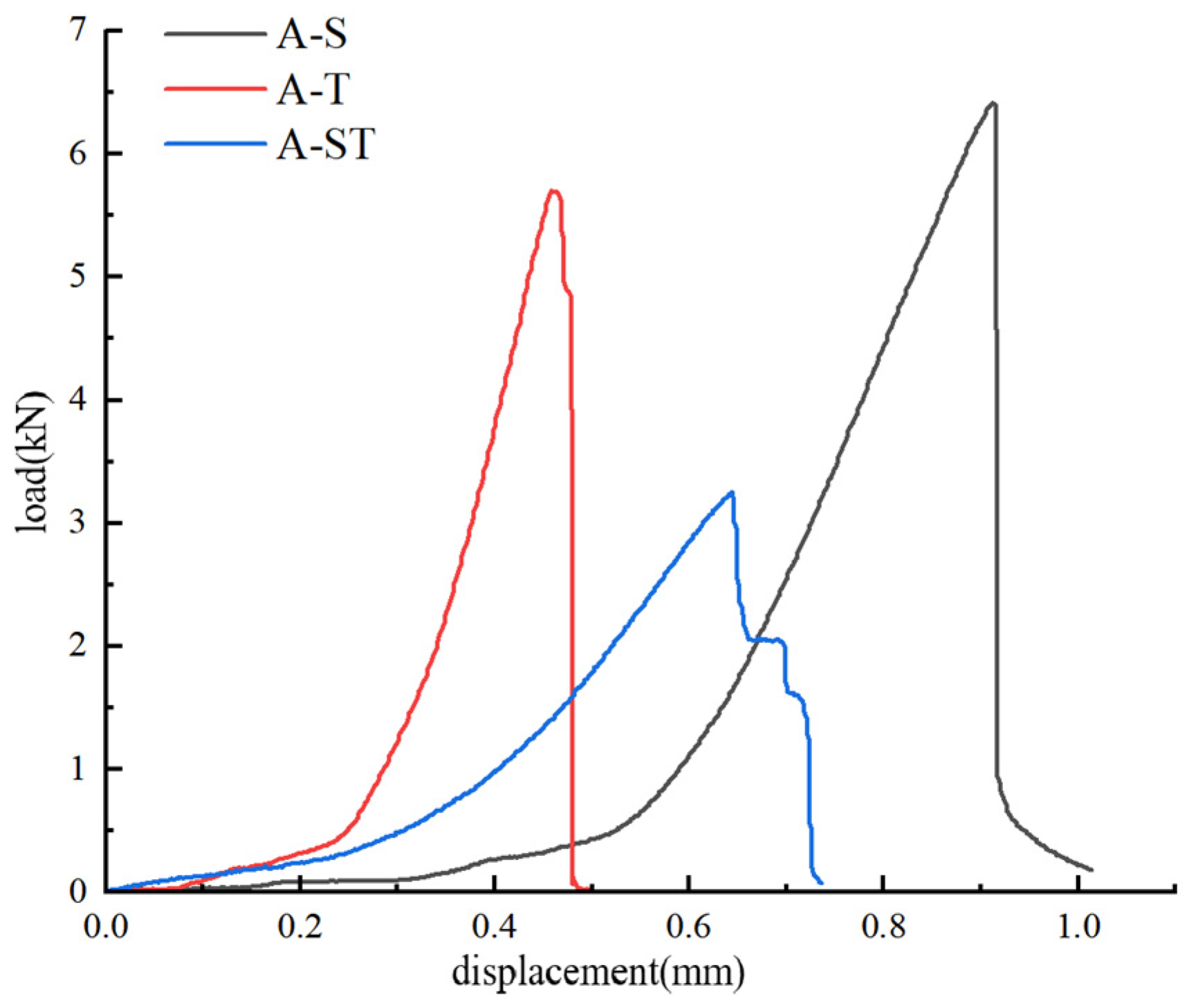
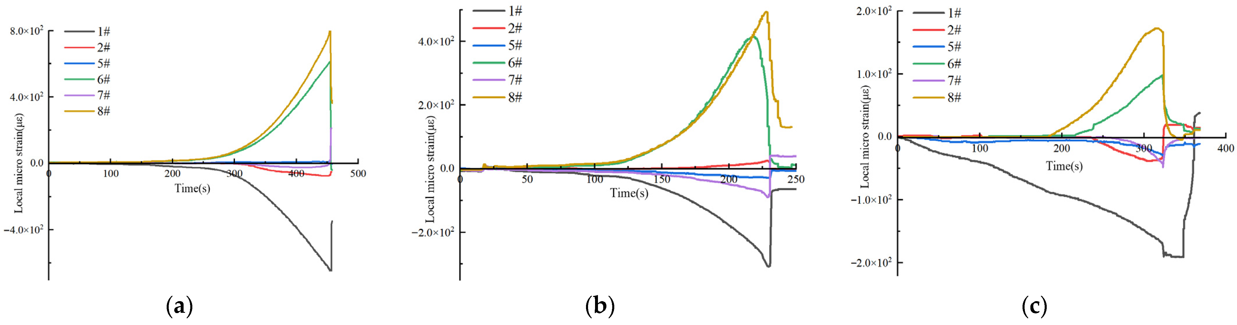
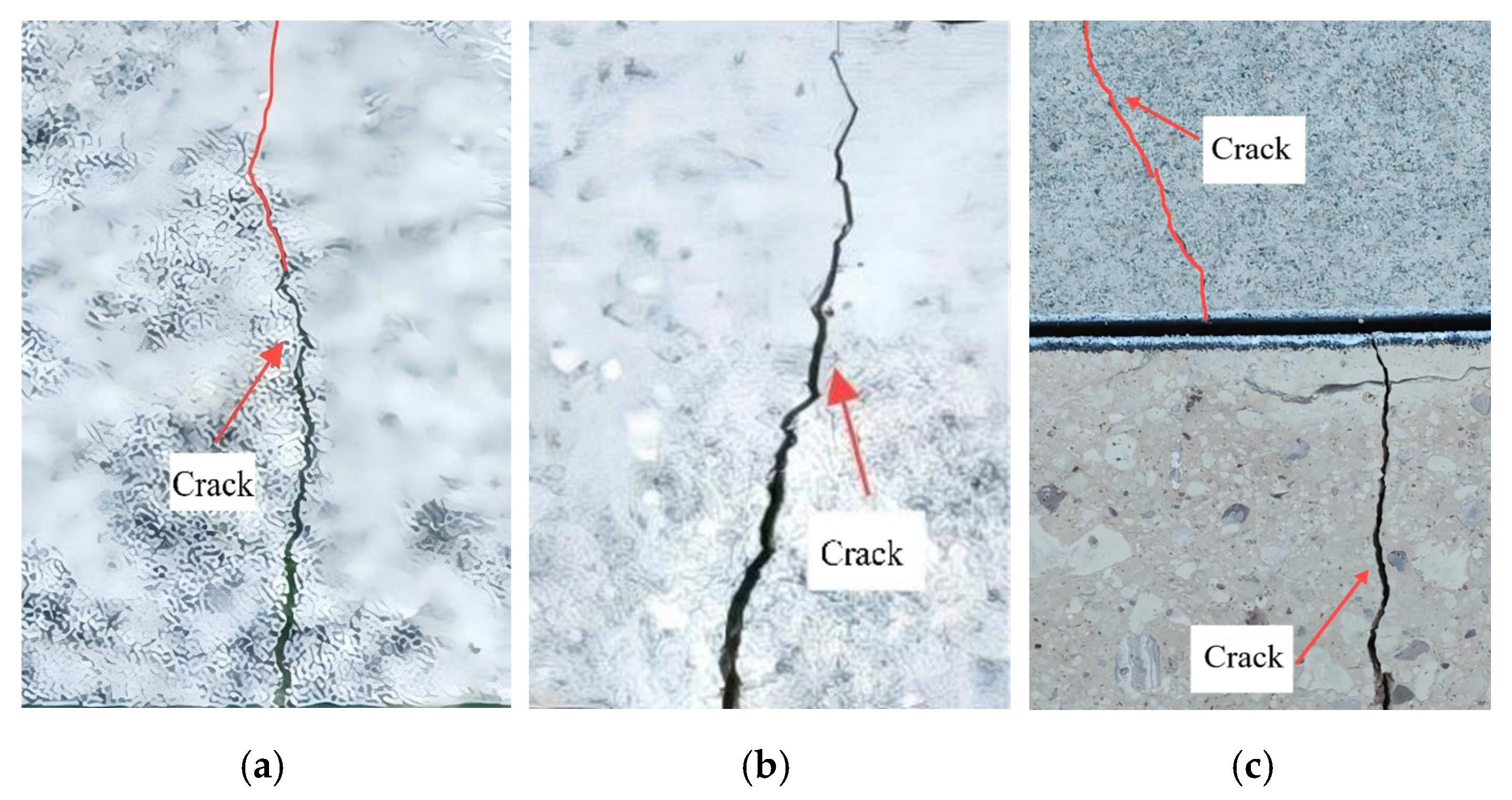
It can be seen from
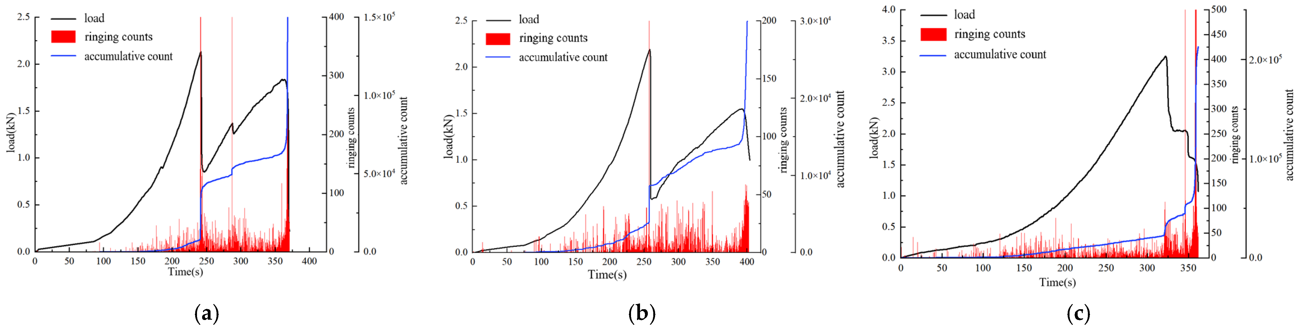
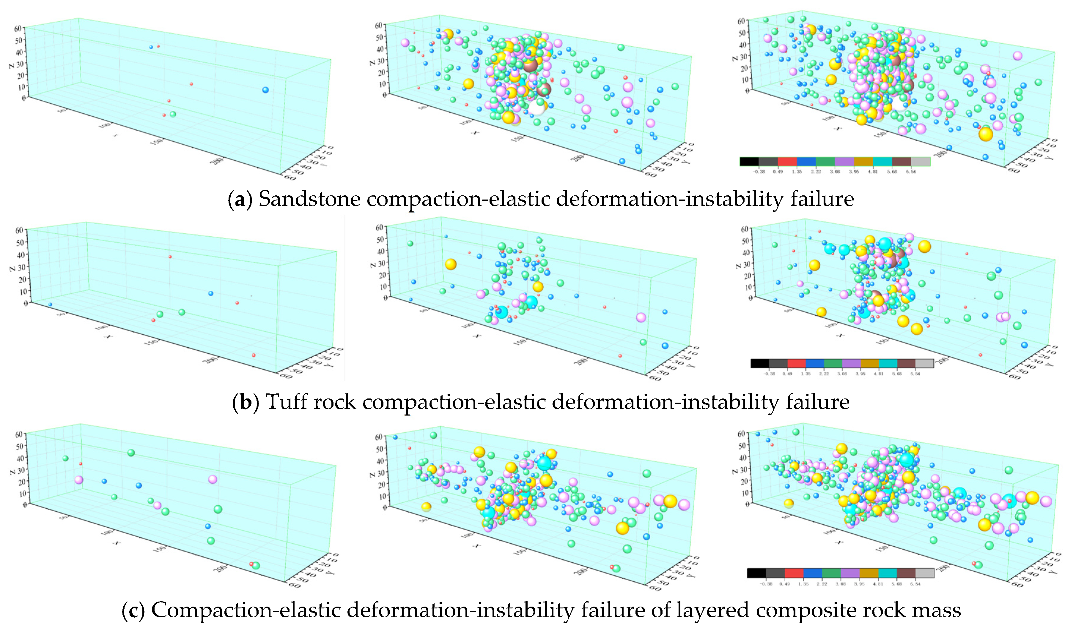
Figure 9 that the pure fine sandstone specimen has high flexural strength, and the crack propagation presents progressive characteristics. Strain gauge data show that microcracks gradually accumulate along grain boundaries in the elastic stage, and a penetrating Type I main crack is formed after the peak load. The fracture surface has high roughness, indicating ductile fracture characteristics; the flexural strength of the pure tuff specimen is 4.75 MPa, with significant brittleness. Cracks initiate in the mid-span area and then penetrate rapidly, and the fracture surface is smoother than that of the pure fine sandstone specimen, accompanied by a small number of radial secondary cracks.
Compared with pure single-lithology rock mass specimens, the layered composite rock mass exhibits an obvious layered failure phenomenon, and the cracks generated at the interface are Type II cracks. When no macroscopic cracks develop in the lower tuff layer, the layered composite rock mass bears the load as a whole, and a peak load is generated when the lower tuff layer reaches the critical state of crack initiation. During the development of cracks in the lower layer, the bearing capacity decreases significantly. Although the tuff layer loses its bearing capacity due to penetrating failure, it is difficult to observe the compaction stage of the upper fine sandstone layer at this time because it is in a high-load period, which manifests as elastic deformation. The second peak load is reached when the overall instability occurs. Due to the short interval between the layered fracture stage and the complete instability stage—and in practical engineering—rock layer layered fracture is a serious instability accident, and separately dividing the stages is not consistent with reality. Therefore, the unified layered fracture stage and bending instability stage are referred to as the instability failure stage. The crack path of the layered composite rock mass is regulated by the interface mechanical properties. Interface bonding enables the compressive strain of the lower rock mass to inhibit the tensile strain of the upper fine sandstone, delays crack penetration, and finally the local strain is significantly lower than that of the pure fine sandstone specimen. This indicates that the interface bonding can significantly improve crack resistance, but it is necessary to prevent interlayer dislocation leading to stress concentration.
4.3. Crack Development Analysis of Layered Composite Rock Mass Under Different Loading Rates
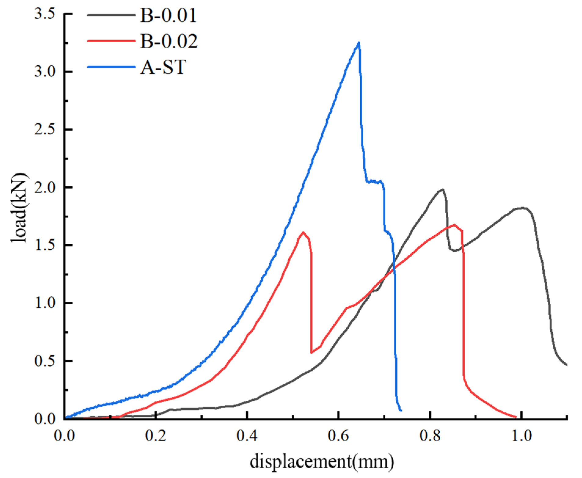
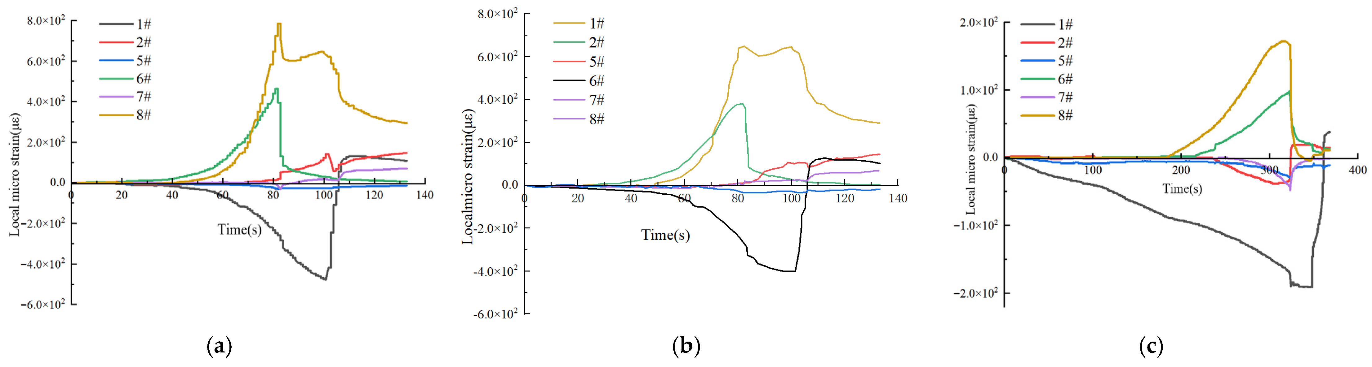
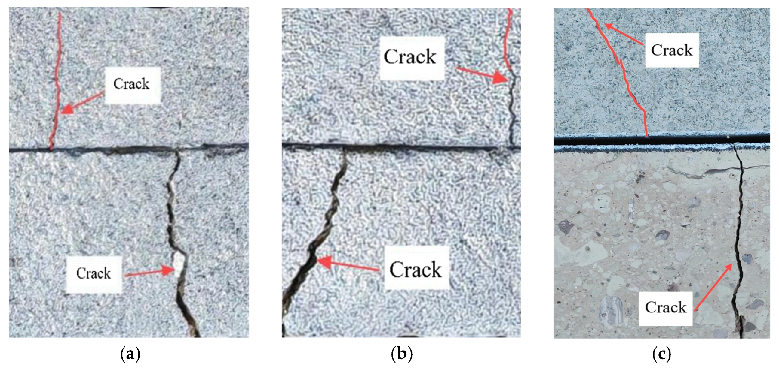
It can be seen from
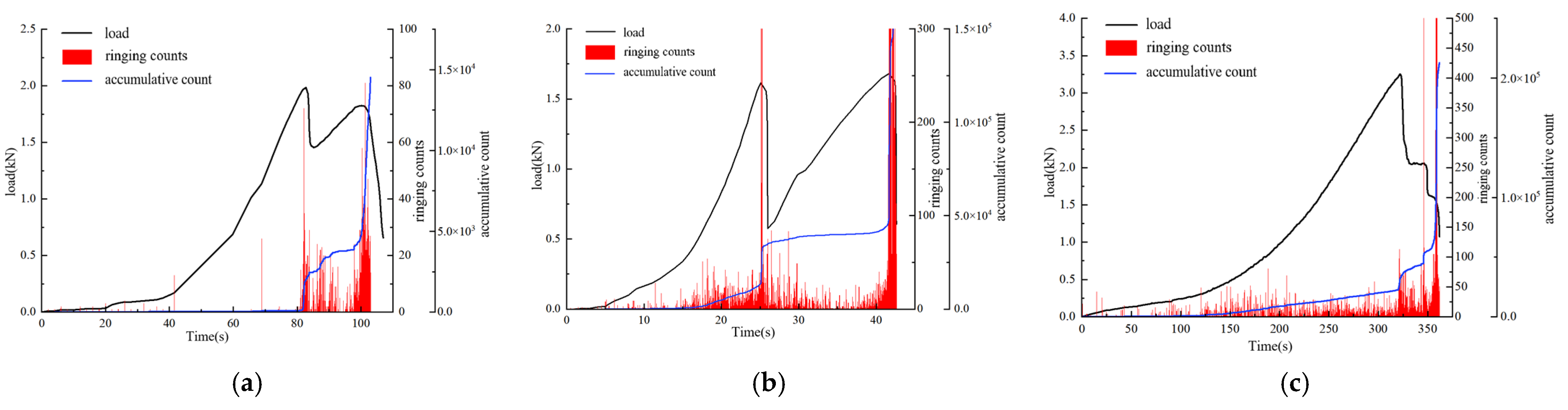
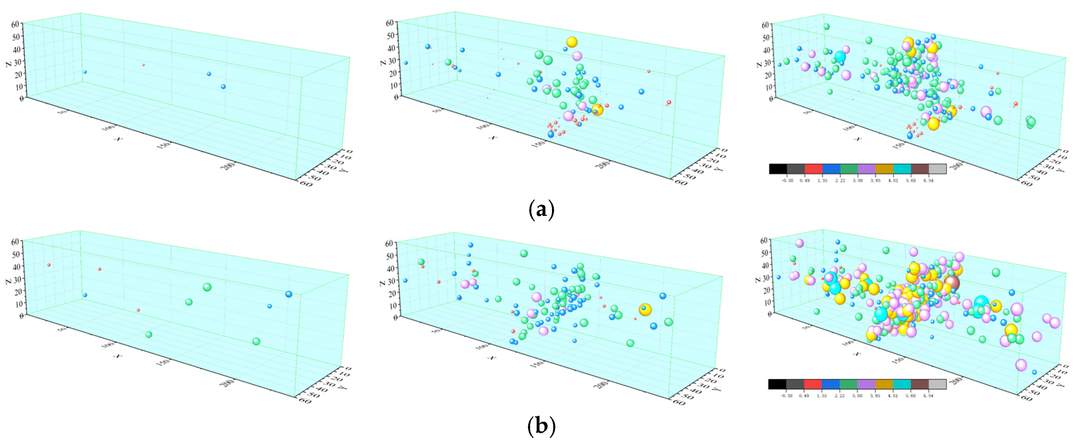
Figure 10 that under low-speed loading conditions, microcracks at the interface are dominated by accumulation, with a low propagation rate and tortuous crack paths. The accumulated energy is gradually released through plastic deformation, avoiding sudden instability failure caused by insufficient bearing capacity. The gentle strain gradient at the interface recorded by strain gauge 2 indicates high stress transfer efficiency, which delays the initiation of the main crack.
Under high-speed loading conditions, the external energy input rate exceeds the energy dissipation capacity of the interface, resulting in the sudden penetration of Type II and Type I cracks. The crack path is straight with significant brittle fracture characteristics. Strain gauge 2 records an instantaneous strain jump, with a peak microstrain of 152, indicating that local stress overload triggers unstable crack propagation.
In this experimental design, 0.01 mm/s is taken as the critical rate. When the loading rate is higher than 0.01 mm/s, the interface cooperative bending deformation effect of the layered composite rock mass weakens, and the crack propagation mode transforms from “plastic accumulation” to “brittle dominance”, showing that rate control is crucial to suppressing sudden failure.
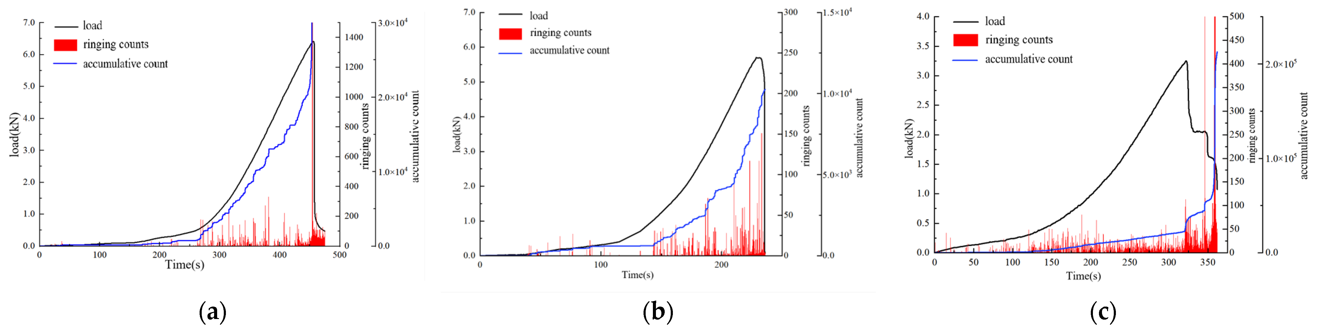
In addition, under low-speed loading, the macroscopic crack development time of the layered composite rock mass is 322 s, which falls between 231.5 s for the tuff specimen and 456 s for the fine sandstone specimen. This indicates that the interfacial synergistic effect delays layered failure. Under high-speed loading, however, the overall instability of the layered composite rock mass occurs at only 41.7 s, implying reduced interfacial stress transfer efficiency and aggravated layered failure.
This phenomenon can also be explained by the time-dependent crack propagation mechanism. At low loading rates, the crack tips have sufficient time to seek weak zones, resulting in longer crack paths and higher crack propagation resistance. Meanwhile, during the slow crack development, frictional slip gradually occurs at the interfacial contact surface. The rock mass dissipates the internally accumulated energy through friction, further slowing down the development of the main crack.
4.4. Crack Development Analysis of Layered Composite Rock Mass Under Different Spans
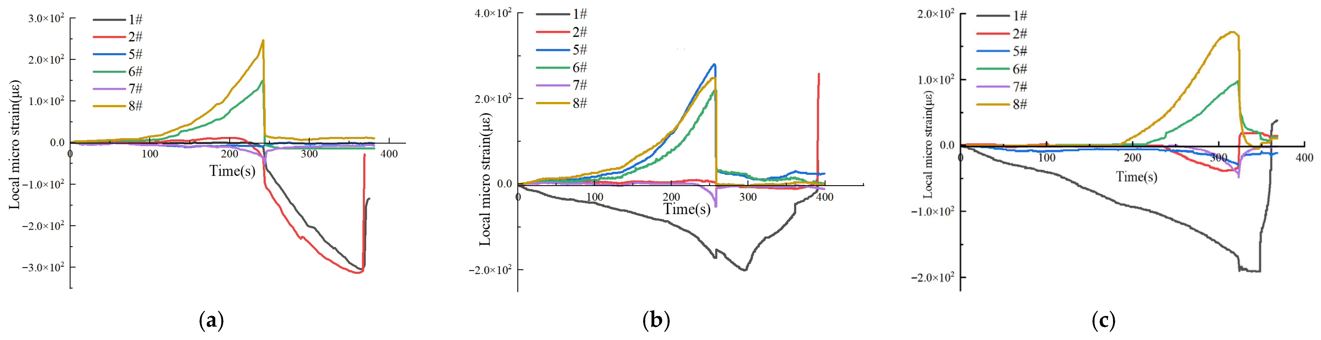
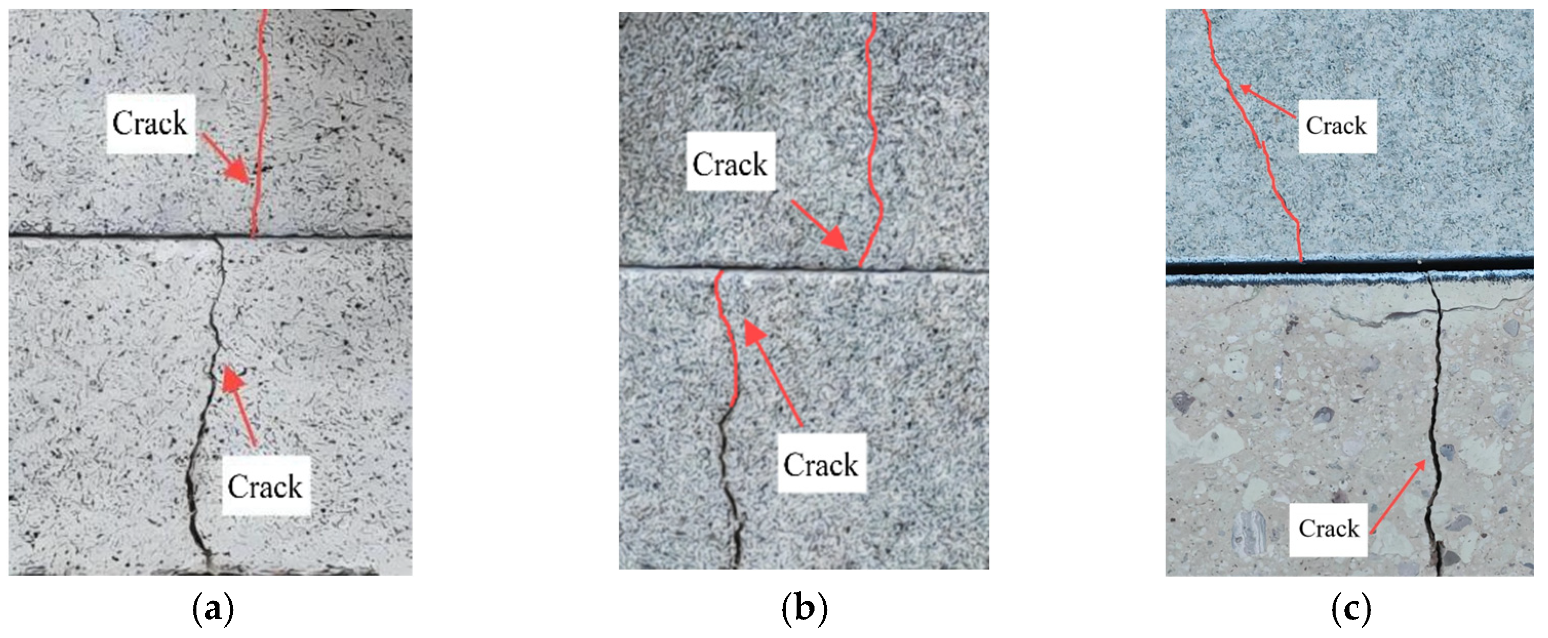
It can be seen from
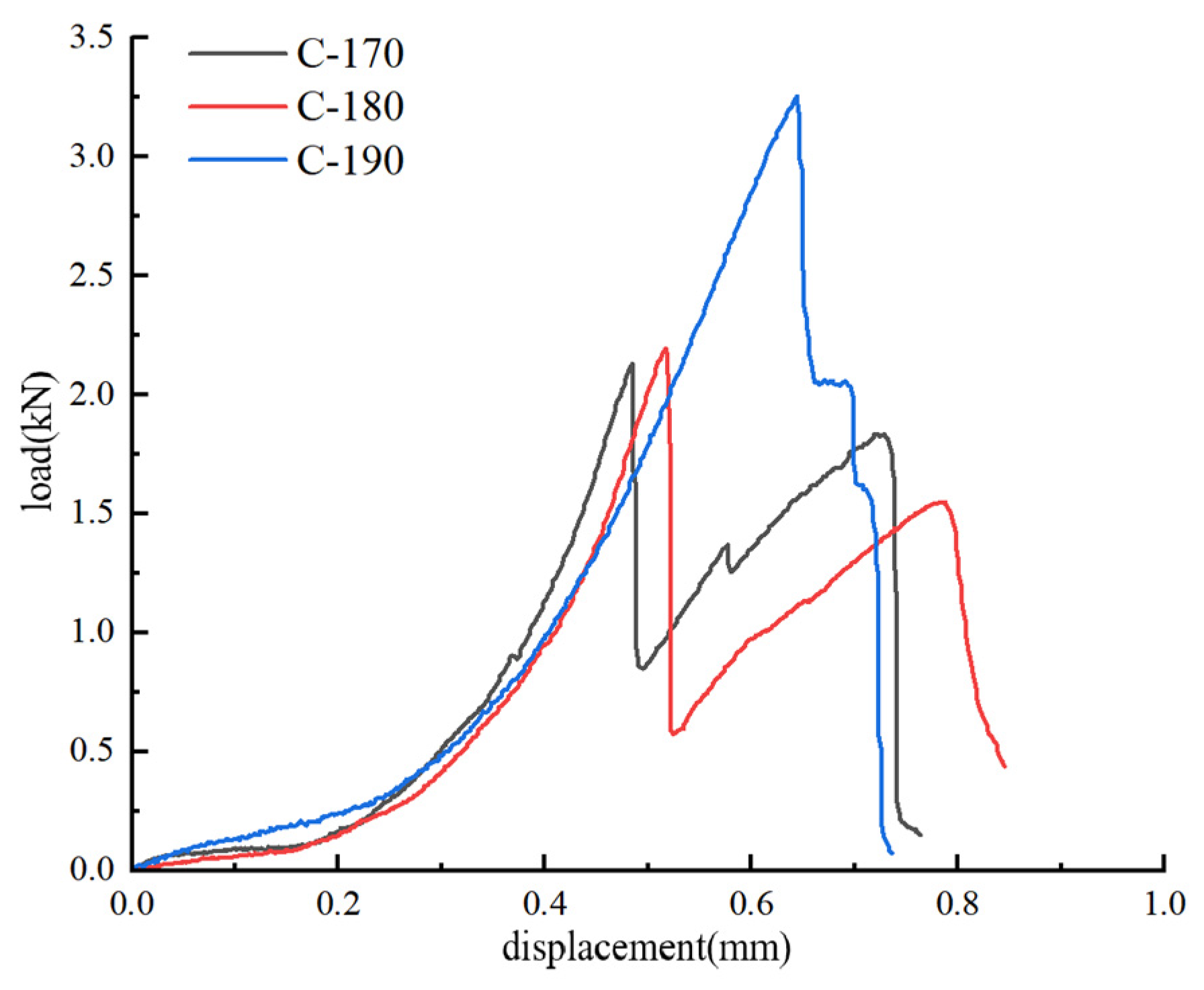
Figure 11 that for the layered composite rock mass with a small span of 170 mm, the load is concentrated near the loading points. Type II cracks first occur in the contact area at the interface. Type I cracks rapidly initiate in the mid-span region of the lower tuff layer at 242 s, showing vertical development and a short propagation path with a propagation time of 118 s, and no obvious bending deformation is observed. The sharp increase in the strain gradient at the interface recorded by strain gauge 2 indicates a significant stress concentration effect. Under the medium span of 180 mm, the crack initiation position shifts toward the mid-span, but the interface remains the stress concentration zone, and Type II cracks at the interface become more obvious. The crack development path begins to show an inclined propagation trend. Under the large span of 190 mm, the bending stress is distributed uniformly. Cracks initiate at the mid-span and propagate obliquely along the interface, with longer paths, longer propagation times and finer cracks. The absolute value of the mid-span strain recorded by strain gauge 2 decreases from 97
at 170 mm to 35
. This shows that increasing the span raises the effective bearing length of the layered composite rock mass and leads to a uniform distribution of bending stress at the mid-span interface.
The peak local tensile strain of the lower tuff layer decreases from 247 at 170 mm to 172 at 190 mm. Increasing the span leads to a more uniform bending stress distribution by extending the load path, which delays the tensile stress concentration in the mid-span of the tuff. This difference in stress distribution postpones the fracture of the tuff layer, but the interface slip increases synchronously.
6. Conclusions and Innovations
6.1. Conclusions
(1) Based on four-point bending tests, the influences of lithology, loading rate and span were analyzed. The flexural strength of layered composite rock mass is significantly lower than that of single-lithology rock mass, which is reduced by 46.7% and 41.1% compared with hard rock mass and soft rock mass, respectively. When the loading rate increases from 0.002 mm/s to 0.02 mm/s, the flexural strength of layered composite rock mass decreases by 51.8%. When the span increases from 170 mm to 190 mm, the flexural strength increases by 65.7%. The competition mechanism between interfacial slip and delamination fracture is the core inducement of strength deterioration.
(2) The bending deformation and failure of layered composite rock mass are characterized by small deformation amplitude and strong sensitivity to influencing factors, and the mid-span deflection is obviously lower than that of single-lithology rock mass. At a loading rate of 0.02 mm/s, the mid-span deflection is reduced by 50.1% compared with that at 0.002 mm/s, indicating that the increase in loading rate restrains the bending deformation capacity. When the span of layered composite rock mass increases from 170 mm to 190 mm, the mid-span deflection increases by 65.7%. The increase in span can prolong the bending deformation path, suppress local stress concentration, and improve the coordination of bending deformation of layered composite rock mass.
(3) Based on acoustic emission monitoring data, the crack evolution laws of layered composite rock mass under different lithology, loading rate and span were obtained. Layered composite rock mass is dominated by Mode II cracks, while single-lithology rock mass mainly develops Mode I cracks. Under low-speed loading, the ring count is low and dense, which promotes the accumulation of microcracks and the development of Mode I cracks; under high-speed loading, the ring count is high and concentrated, inducing brittle fracture with more prominent Mode II cracks. With the increase in span, the failure mode transits from brittle failure concentrated near loading points to bending failure dominated by the mid-span region.
(4) Mineral grain size and cement properties have significant effects on the strength and crack development of layered composite rock masses: the coarse-grain and strong cementation characteristics of fine sandstone lead to progressive development of microcracks along grain boundaries, showing good ductility. The fine-grain and weak cementation characteristics of tuff make microcracks prone to rapid penetration, with significant brittleness. The slip characteristics of interlayer cement directly dominate the development of Mode II cracks, which is an important internal cause of strength deterioration of composite rock masses.
6.2. Innovations
(1) Innovation in test method: The four-point bending test was adopted to eliminate the interference of shear stress, accurately restoring the real stress state of the pure bending section of deep roadway composite roofs, and solving the problem of large deviation between traditional three-point bending test results and engineering practice. A calculation method for the equivalent flexural rigidity of soft–hard interbedded composite rock masses was established, correcting the application error of the homogeneous material beam theory in layered composite rock masses.
(2) Innovation in mechanism cognition: The interfacial effect and mesoscopic mechanism of bending failure of layered composite rock masses under the coupling of multiple factors (lithology combination, loading rate, and span) were systematically revealed. The internal mechanism of strength deterioration of composite rock masses under high loading rates was clarified, resolving the cognitive contradiction with the conventional strain rate effect of homogeneous rocks, and improving the bending failure theory of layered rock masses.
(3) Innovation in damage characterization: Based on the synergy of strain monitoring, high-speed camera, and acoustic emission localization, the temporal and spatial evolution laws of Mode I/II cracks during the bending failure of composite rock masses were quantified. A full-process damage evolution model of “interfacial slip-delamination-overall instability” for layered composite rock masses was established, realizing the refined characterization of the full bending failure process of composite rock masses.
7. Engineering Applications
The research findings of this paper can provide direct theoretical guidance and technical support for the support design of composite roofs and roof disaster prevention and control in deep coal mine roadways. The specific engineering application values are as follows:
(1) For the composite roof in the West No. 1 Mining Area of Shuangyang Coal Mine, it is clarified that the interlayer interface is the core controlling weak surface for roof bending instability. It is proposed that the support of composite roofs should prioritize the use of full-length anchored bolts and cable bolts to enhance interlayer bonding and control interlayer delamination, rather than simply increasing support strength. This provides a core idea for optimizing the support scheme.
(2) Based on the law of the influence of loading rate on the strength of composite rock masses, it is confirmed that the excavation disturbance rate is a key inducement for sudden roof instability. An optimized scheme for advanced support of the working face is proposed: within the influence range of advanced abutment pressure, the support strength should be increased in advance to reduce the impact of excavation disturbance on the roof and avoid sudden roof collapse accidents under high disturbance rates. In the advanced support section of rapidly advancing working faces, compressible temporary support components should be added to reduce the high-speed loading effect caused by excavation disturbance, inhibit sudden brittle fracture of the roof rock mass, and optimize the working face advancing speed to control the loading rate of the roof rock mass below the critical value, thereby delaying crack development.
(3) Based on the research results of the span effect, the design of bolt/cable spacing for roadway roofs is optimized: by increasing the lateral support span of bolts/cables, the bending deformation path of the roof rock mass is extended, the coordinated deformation of rock layers is promoted, local stress concentration is suppressed, the overall flexural bearing capacity of the roof is improved, and the long-term stability of surrounding rock in deep roadways is guaranteed. At the same time, the effective bearing span of the roof should be appropriately increased to release stress through the bending deformation of the rock mass and suppress local stress concentration.
(4) Instability monitoring and early warning: Based on the evolutionary characteristics of acoustic emission ringing counts, it is taken as the core early warning indicator for composite roof instability. When the underground microseismic monitoring system detects that the ringing counts of the roof rock mass show the characteristics of “high value and concentrated burst”, it is judged as a precursor to brittle roof failure. In such cases, excavation operations should be stopped in a timely manner, and emergency support measures should be activated to prevent and control roof collapse accidents.