Article

Large-Scale Mine Experimental Study on the Crack Extension Law of Deep-Seated Coal Rock

1
Sinopec North China Petroleum Bureau, Zhengzhou 450006, China
2
School of Petroleum Engineering, China University of Petroleum (Beijing), Beijing 102249, China
*
Author to whom correspondence should be addressed.
Processes 2026, 14(5), 754; https://doi.org/10.3390/pr14050754
Submission received: 27 October 2025 / Revised: 11 December 2025 / Accepted: 26 January 2026 / Published: 25 February 2026
(This article belongs to the Section Energy Systems)

Abstract

Deep-seated coalbed methane (CBM) resources in the Daniudi Gas Field of the Ordos Basin are abundant; however, conventional laboratory-scale hydraulic fracturing experiments are unable to realistically reproduce fracture propagation behavior due to pronounced reservoir heterogeneity and the complex development of bedding and cleat structures. In this study, a self-developed 10,000-ton true triaxial hydraulic fracturing simulation platform was employed to conduct mine-scale experiments using large 2 m × 2 m × 1 m No. 8 coal-rock outcrop specimens. A full-scale steel-casing wellbore and an industrial fracturing fluid system were incorporated to replicate field conditions. Experiments were performed under varying pumping rates (0.2–0.4 m3/min) and fracturing fluid viscosities (10–50 mPa·s). The results indicate that post-failure fractures in deep coal formations primarily develop into complex fracture zones extending vertically from the wellbore. Their morphology is strongly governed by bedding planes and cleats, producing tortuous, banded, and mesh-like patterns. When the fracturing fluid viscosity is maintained between 18 and 27 mPa·s, longitudinal fracture diversion along the wellbore is effectively suppressed, while the increased static pressure promotes the activation of natural fractures. Increasing the pumping rate to 0.4 m3/min markedly enhances the stimulated reservoir volume (SRV), with an increase of approximately 1354%, and significantly increases fracture branch density. However, higher viscosities (>27 mPa·s), despite promoting fracture complexity, reduce proppant transport efficiency due to increased in-fracture tortuosity. This study quantitatively characterizes the coupled responses of fracture volume fraction, branch density, and fracture-surface roughness, and elucidates the interplay between displacement and viscosity in governing fracture network evolution. The findings provide an important experimental foundation for optimizing hydraulic fracturing parameters in the efficient development of deep-seated CBM reservoirs.

1. Introduction

The Daniu Di Gas Field in the northeastern Ordos Basin, as a significant unconventional energy base in China, features a superimposed reservoir system composed of Shanxi Formation Coal No. 5 and Taiyuan Formation Coal No. 8. Buried at depths of 2400–3000 m, its coalbed methane resources are conservatively estimated to exceed 12 × 1012 m3 [1,2]. This reservoir exhibits typical deep coalbed geological characteristics: (1) High heterogeneity leads to significant spatial variation in mechanical parameter fields; (2) Multi-level bedding planes and dense joint systems form complex fracture networks; (3) Dynamic migration properties of supercritical adsorbed gas within nano- to micrometer-scale pore systems [3,4]. These characteristics collectively limit the applicability of conventional fracturing theory in deep coalbed methane development. The meandering propagation of fractures during hydraulic fracturing and the coupled mechanism of gas desorption-diffusion seepage represent key scientific challenges constraining recovery enhancement [5,6,7].
Regarding research on the hydraulic fracturing mechanism of deep coal-rock formations, physical simulation experiments have become the core technical approach for revealing the dynamic expansion patterns of fractures [8,9]. In recent years, scholars have achieved significant progress through experimental systems at different scales: at the fundamental mechanical response level, Anderson et al. [10] used 10 cm3 rock samples to reveal the critical stress criterion for fracture propagation across coal-rock interfaces; Meng et al. [11] used a true triaxial system to confirm the key role of in-fracture pressure gradients in activating natural fractures, proposing a coupled control mechanism involving interlayer stress differences and lithological interfaces; Gao, et al. [12] discovered the interlayer advantage effect of high-viscosity fracturing fluids through coal-sand composite rock experiments, revealing the topological constraints imposed by natural fracture networks on fracture pathways within coal bodies. Sharma et al. [13] conducted in-depth research on the hydraulic fracture propagation law of reservoirs with natural fractures based on the finite element fluid-solid coupling theory, revealing that the angle between hydraulic fractures and natural fractures as well as the horizontal principal stress difference control the formation of hydraulic fracture networks. Fu et al. [14] classified the interaction between hydraulic fractures and natural weak planes in coal samples into four modes (truncation, deflection, branching, and crossing) based on triaxial experiments. Xie et al. [15] pointed out that when hydraulic fracturing intersects with natural weak planes, five basic modes are exhibited, namely non-expansive penetration, expansive penetration, branching, derivation, and deflection. Men et al. [16] and Zhang et al. [17] revealed that hydraulic fractures are more likely to propagate along the bedding planes when their contact angle is small. Regarding microstructural influences, Fan et al. [18] developed a stress-dominated, structure-fine-tuned fracture propagation model based on joint orientation experiments. Hu, T. [19] quantified the regulatory impact of spatial Young’s modulus variation on joint length (ΔL = 23%) and width (Δω = 18%) through mechanical parameter sensitivity analysis. Liu et al. [20] combined field data with numerical simulations to establish a dynamic response equation linking seepage patterns with fracture height, flow velocity, and pressure. Bai et al. [21,22] employed Nuclear Magnetic Resonance (NMR) to determine the T2 spectra of specimens at different loading stages and monitored the dynamic evolution law of the internal pore structure. Sun et al. [23] analyzed the dynamic variation law of core porosity based on Scanning Electron Microscopy (SEM) and Computed Tomography (CT) techniques. Badulla et al. [24] used SEM to investigate the evolution of the fracture process zone at the crack tip of pre-cracked marble under axial load, revealing that the microcrack density in the fracture process zone increases with the increase of axial load.
Despite the establishment of multi-scale experimental methodologies through existing research, significant limitations persist when addressing the unique geological conditions of the deep reservoirs at the Daniu Di field: (1) Traditional experimental specimens (<1 m3) struggle to characterize kilometer-scale stress boundary effects; (2) Deviations from similarity criteria result in substantial discrepancies between laboratory fracture morphology (meandering angle < 15°) and actual engineering observations (meandering angle > 10 m3) [25]; (3) The feedback mechanism of adsorbed gas dynamic desorption on fracture propagation under multi-field coupling remains unclear. This necessitates the establishment of a large-scale (>10 m3) true triaxial physical simulation platform. Through geological mechanics reconstruction, real-time multi-parameter monitoring, and digital image correlation techniques, this platform will systematically reveal the formation and evolution patterns of fracture networks during deep coal-rock hydraulic fracturing, providing theoretical support for process optimization in development.

2. Extra-Large True Three-Axis Hydraulic Fracturing Mine Field Test Platform

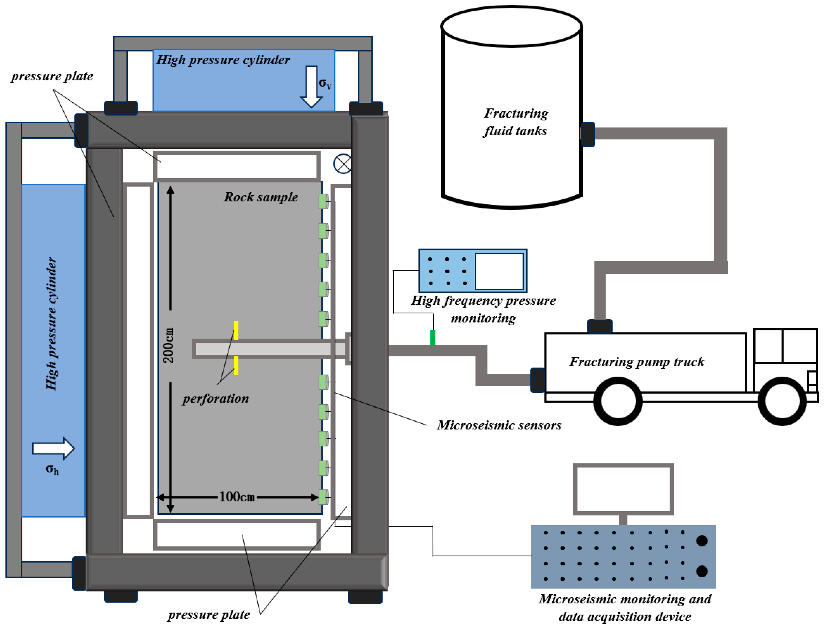
Large-scale deep coal-rock hydraulic fracturing physical simulation experiments were conducted using an ultra-large-scale true triaxial hydraulic fracturing mining field experimental platform (Figure 1) to simulate the hydraulic fracture propagation process under real-world conditions. This platform comprises three core systems:
(1) Stress Loading System—Utilizing a 10,000-ton hydraulic pump station to drive pressure-bearing steel plates, it achieves ultra-high stress loading exceeding 50 MPa in both the maximum horizontal principal stress direction and vertical direction (no load applied in the minimum horizontal principal stress direction due to structural design). Its stress loading magnitude closely matches in-situ reservoir stress levels, overcoming the technical bottleneck of high-precision stress loading on large-scale specimen surfaces.
(2) Fluid Preparation System—Equipped with a 1 m3 industrial-grade storage tank, it strictly regulates additive ratios (including anti-settling fluorescent dyes) according to field fracturing fluid formulations. This enables precise replication of fracturing fluid systems across a viscosity range of 2–200 mPa·s, expanding traditional laboratory intermediate container capacity by three orders of magnitude;
(3) Fluid Injection System—Integrated with a 700-type fracturing pump truck, industrial casing wellbore, and high-pressure manifold, enabling precise control of single-hole equivalent flow rates (0.5–3 m3/min corresponding to reservoir conditions). Notably, a real casing system replicates the wellbore, synchronously restoring the coupled effects of casing-cement annulus-formation interaction and wellbore deformation.
Compared to conventional indoor experimental setups, this platform offers significant advantages: Sample dimensions are scaled up to the meter level (2 m × 2 m × 1 m), stress loading capacity increases by 8–10 times, and pumping discharge expands by four orders of magnitude. Furthermore, critical equipment—including casing, fracturing fluid, and pumping systems—utilizes field-proven oil and gas field tools. This achieves an integrated “material-equipment-process” engineering-scale experimental environment, providing a high-fidelity physical simulation for elucidating fracture propagation mechanisms in deep coal and rock formations.

3. Experimental Protocol

3.1. Rock Sample Preparation

Referencing the actual rock mechanics parameters of coal seams in the Daniu Di Gas Field, the large-scale No. 8 coal-rock outcrop was selected for sampling. Rock mechanics tests and fundamental physical property tests were conducted on the collected coal-rock outcrop samples, followed by comparative analysis with the No. 8 coal from the Daniu Di Gas Field. The coal seam exhibits extremely well-developed cross-cutting and end-cutting fractures. These fractures form a network that dissects the coal into smaller blocks. Mirror coal bands are visible on the fracture surfaces, with pyrite filling observed on some fracture planes.
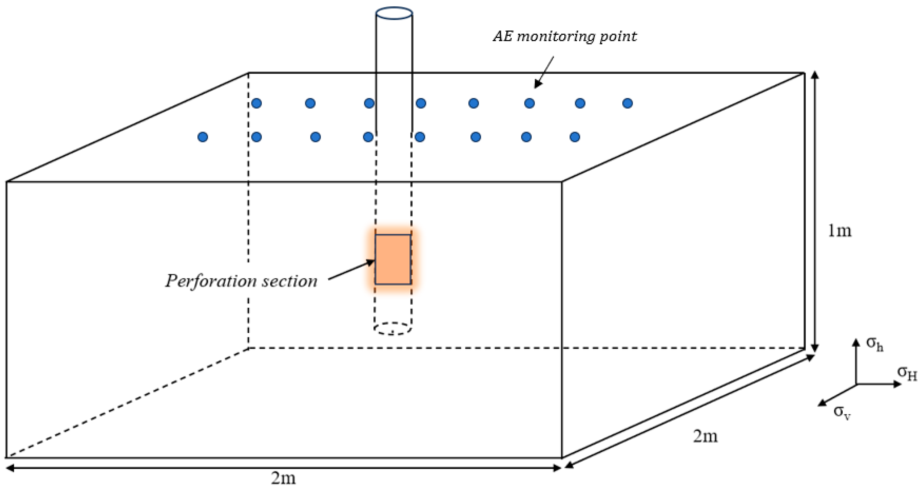
Large-scale construction machinery was used to collect coal-rock outcrop samples. These were cut, processed, and prepared using cement plasticity on the outer surfaces. After processing, standardized rock samples reached dimensions of 2 m × 2 m × 1 m. Following specimen curing, a simulated wellbore was constructed using casing with an inner diameter of 116.79 mm. Pre-perforations were installed according to the test plan (Figure 2). Cementing was completed using Grade G cement, with the cement annulus undergoing proper curing to ensure qualified cementing quality.

3.2. Experimental Procedures and Protocol

The experimental procedure is as follows:
(1) Install the specimen lifting device into the oversized true triaxial stress loading apparatus;
(2) Prepare fracturing fluid with the required viscosity according to experimental needs, thoroughly mixing to prevent “fish eyes” and sedimentation;
(3) Connect the fracturing manifold to the fracturing pump truck and casing simulation well, then circulate fracturing fluid at low pressure to verify the integrity of all pipeline connections;
(4) Position acoustic emission monitoring probes to ensure effective operation of monitoring equipment; (Sixteen AE sensors (blue dots in Figure 2) were arranged on the top and lateral faces of the specimen to provide full 3D coverage for accurate microseismic monitoring).
(5) Inspect the sealing integrity of all hydraulic system valves to guarantee safe experimental conduct;
(6) Activate the fracturing pump truck to initiate the hydraulic fracturing field test;
(7) Use acoustic emission monitoring for preliminary assessment of internal fracture distribution characteristics in rock samples. Quantify surface fracture widths using a fracture gauge to characterize spatial fracture distribution patterns and fracture surface features.
Referencing actual construction parameters from the Daniu Di Gas Field, the experimental design (Table 1) focuses on investigating the effects of pumping rate and fracturing fluid viscosity on fracture propagation.

3.3. Data Acquisition and Image Processing Procedures

Parameters A (fracture area) and w (fracture width) were extracted from surface Digital Image Correlation (DIC) images using a threshold-based segmentation algorithm (spatial resolution 0.1 mm/pixel). The fracture height irregularity (h_i) was obtained from 3D surface models constructed by a handheld structured-light scanner after specimen dissection. Measurement uncertainties were ±0.2 mm for width, ±0.5 mm for height and ±3% for area.

4. Analysis of Experimental Results

4.1. Pump Discharge Volume Impact

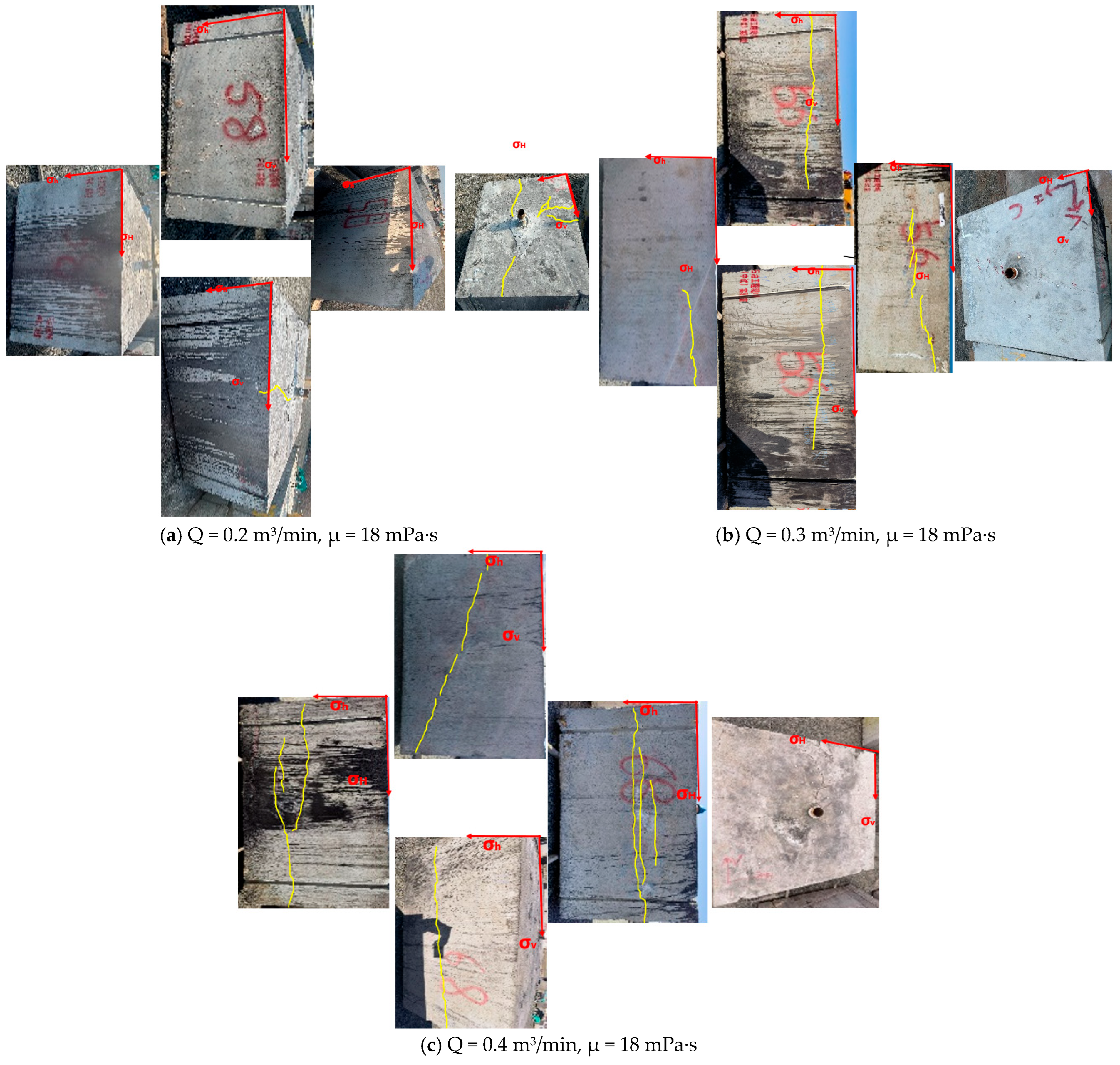
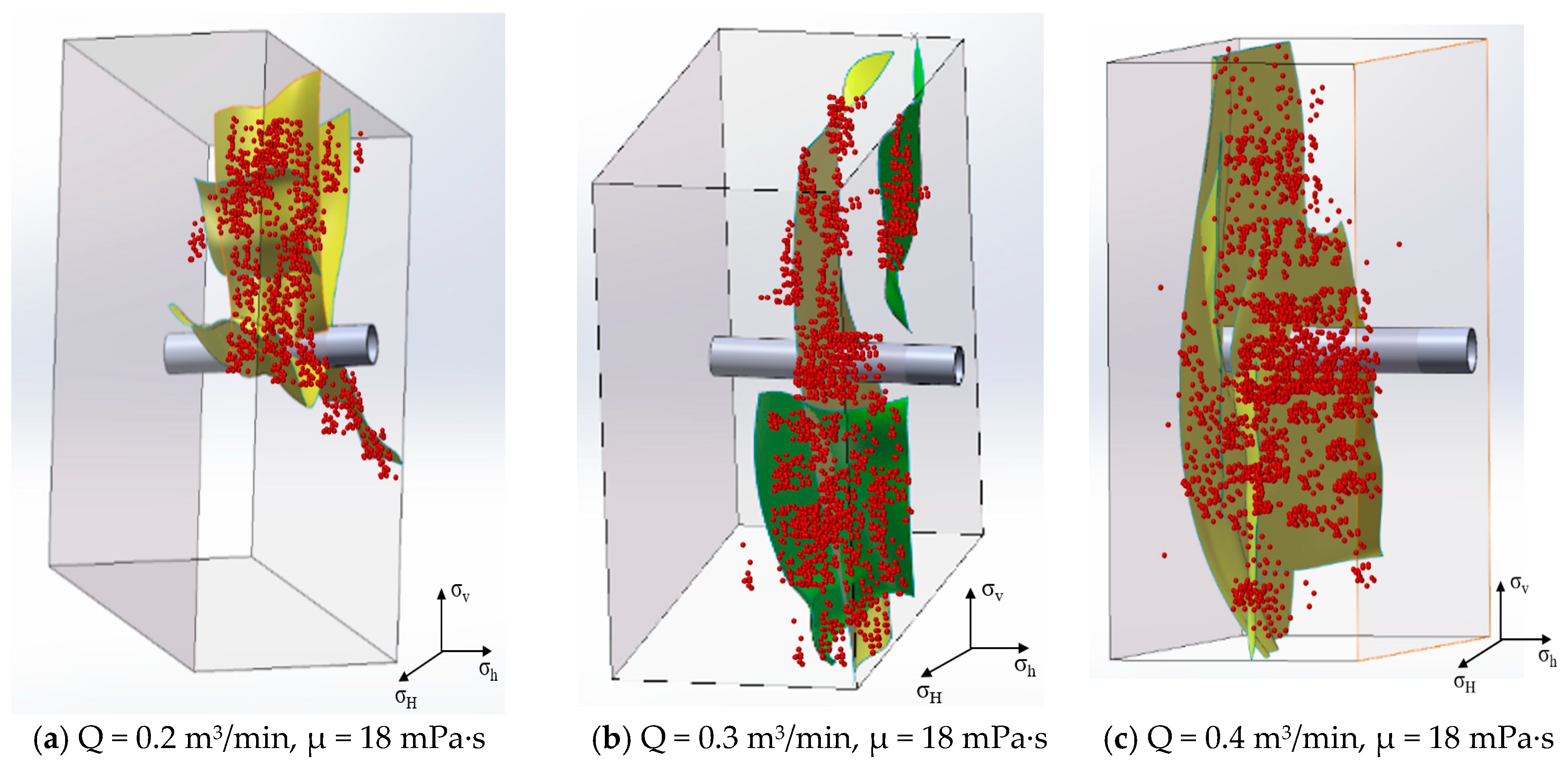
Analysis of fracture distribution characteristics under different pumping flow rates (Figure 3) reveals that most post-coal-rock compression fractures propagated perpendicular to the wellbore axis. A small number of fractures exhibited tangential propagation along the wellbore direction, displaying a tortuous morphology with primary and secondary fractures distributed in an interlaced pattern. Wandering fractures primarily formed under low-injection-rate conditions. As the injection rate increased, fractures tended to propagate along the vertical shaft direction. The number of fractures showed a positive correlation with the injection rate. Analysis suggests that high-injection-rate operations facilitate communication with more bedding planes and joint planes, thereby increasing the number of branch fractures and enhancing the complexity of the fracture zone.

4.2. Impact of Fracturing Fluid Viscosity

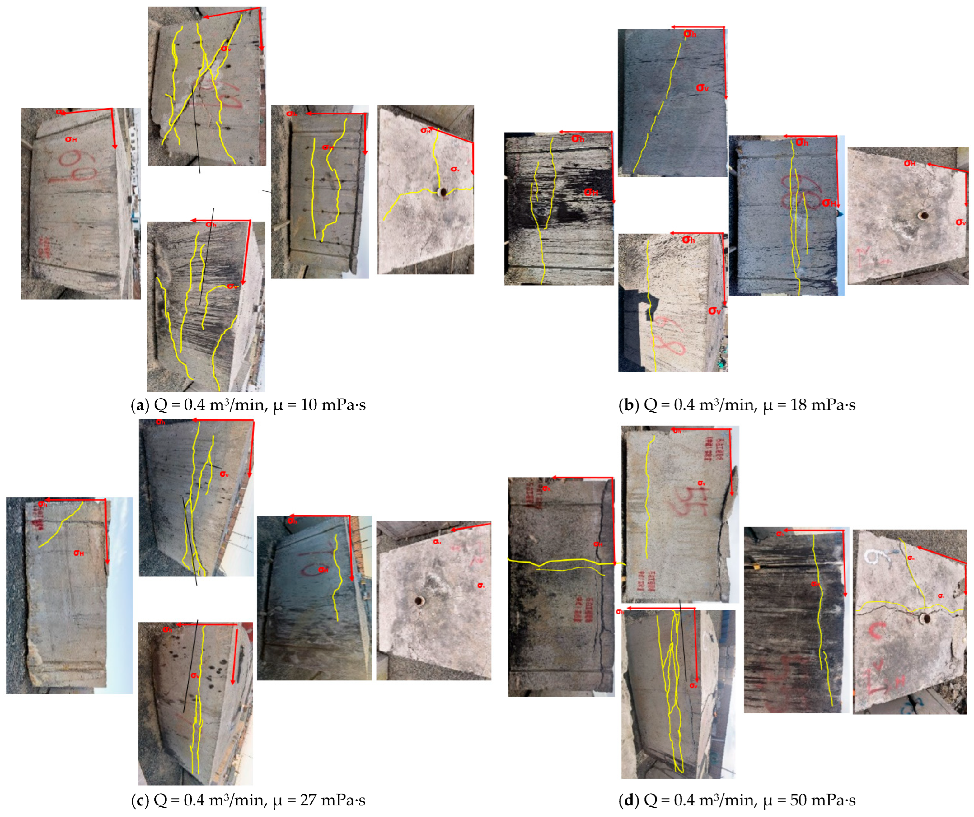
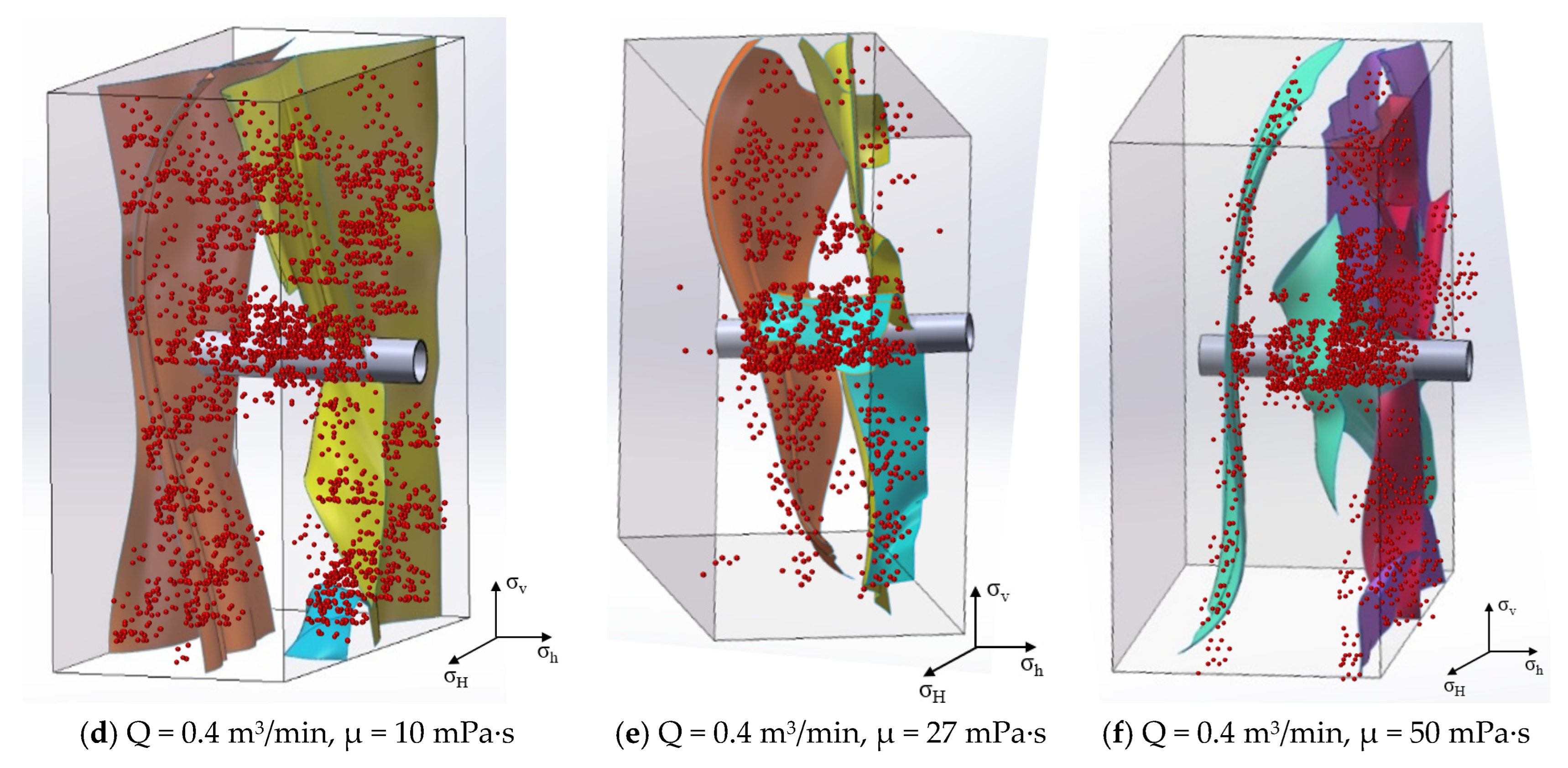
Analysis of fracture morphology under different fracturing fluid viscosity conditions reveals (Figure 4) that fractures primarily propagate perpendicular to the wellbore. Under low-viscosity (10 mPa·s) and high-viscosity (50 mPa·s) conditions, fractures exhibiting tangential propagation along the wellbore are observed. As fracturing fluid viscosity increases, fracture distribution becomes more concentrated and fracture zone density increases. Controlling fracturing fluid viscosity between 18 and 27 mPa·s suppresses longitudinal fracture migration and promotes fracture zone propagation perpendicular to the wellbore.

4.3. SRV Characterization

By characterizing crack width and morphology, combined with microseismic data and crack structure topology algorithms, the evolution of SRV under different operating conditions is characterized.
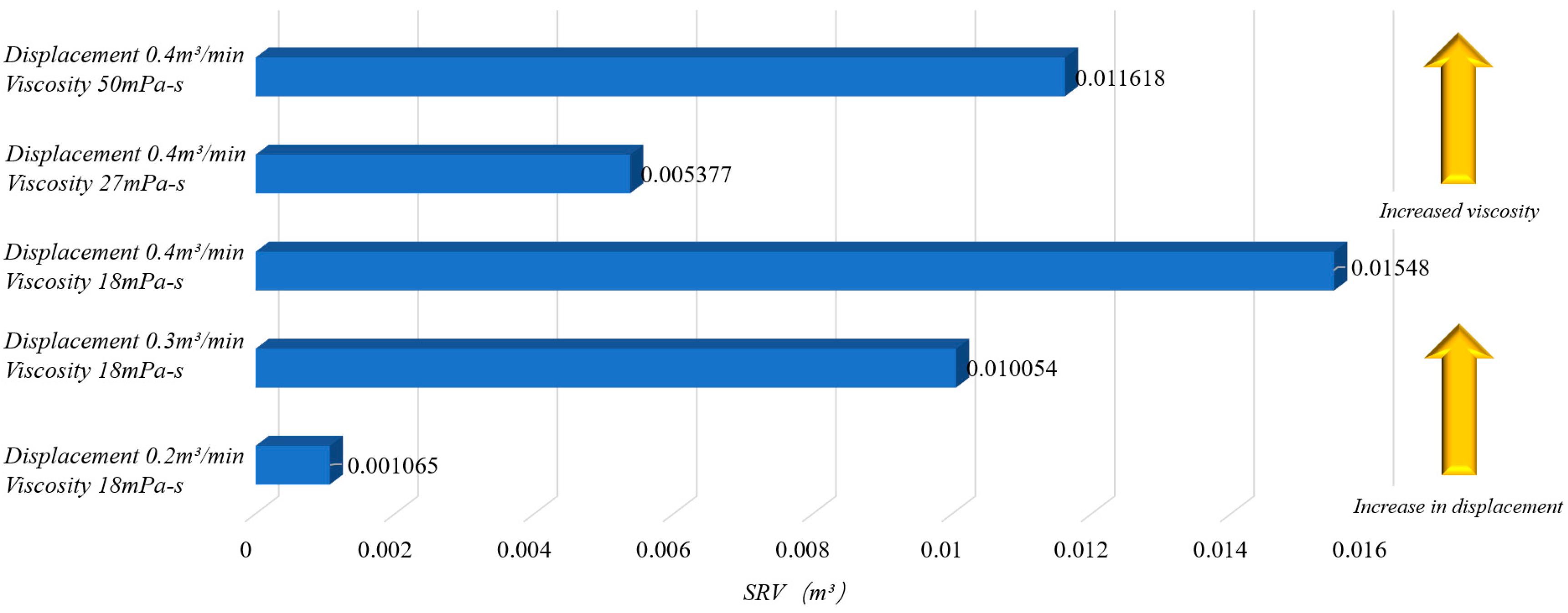
As shown in Figure 5, SRV exhibits extreme sensitivity to variations in pump injection flow rate and fracturing fluid viscosity. An increase in flow rate typically elevates net pressure, promoting fracture propagation and natural fracture activation, thereby amplifying SRV. When flow rate increased from 0.2 m3/min to 0.4 m3/min, SRV surged by 1353.52%. SRV exhibits a trend of first decreasing then increasing with rising fracturing fluid viscosity. Analysis suggests that as fracturing fluid viscosity increased from 18 mPa·s to 27 mPa·s, there was reduced fluid loss, and increased fracture-interval static pressure. However, fluid energy concentrated on primary fracture expansion, activating fewer bedding planes and cross-bedding fractures, thus lowering SRV. As viscosity further increased (to 50 mPa·s), the high-viscosity fluid continuously elevated fracture-interval static pressure, exceeding the tensile strength of natural fractures and activating more fracture branches, causing SRV to rebound.

4.4. Analysis of Fracture Network Morphological Characteristics in Deep Coal Seams

Based on the spatial distribution of effective events identified through multi-channel microseismic monitoring, 3D reconstruction of the spatial distribution patterns of coal-rock fracturing cracks under different operating conditions was performed (Figure 6).
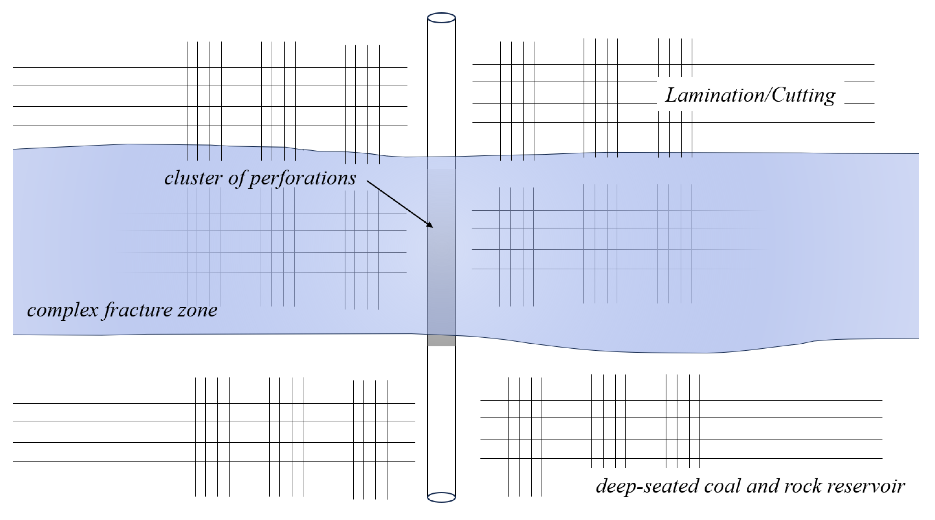
As shown in Figure 7, the spatial distribution characteristics of fractures vary significantly under different operating conditions. Influenced by bedding and joint planes, fractures in deep coal-rock formations propagate distally in the form of complex fracture zones. These zones consist of multiple primary and secondary fractures, which deviate due to geological stresses and natural fractures. Within the fracture zones, numerous fractures intersect and connect, exhibiting a spatially twisted, net-like distribution.
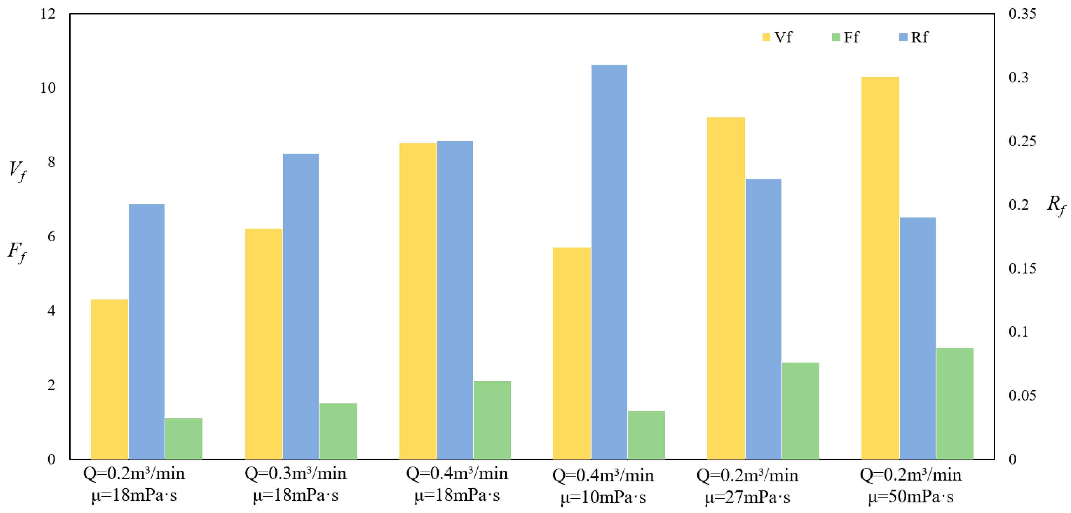
To further quantify the spatial distribution of complex fracture zones in deep coal strata, we analyzed the three-dimensional spatial morphology of fractures. The fracture volume fraction was defined as the ratio of fracture volume to the total volume of the altered zone (see Equation (1)). The branching fracture density was defined as the number of branch fractures per unit length of the main fracture (see Equation (2)). The irregularity of the complex fracture network was defined using the arithmetic mean deviation of the contour (see Equation (3)).
V f = i = 1 n A i · w i ¯ L x L y L z
F f = i = 1 n L i B r a n c h   F r a c t u r e L M a i n   F r a c t u r e
R f = i = 1 n h i h i ¯ n
In the formula:
Vf—Fracture volume fraction, %;
A—Fracture Surface area, m3;
w—Fracture aperture, m;
Lx, Ly, Lz—Spatial dimensions of fractured crack network, m;
Ff—Branching fracture density, dimensionless;
Rf—Fracture surface roughness, m;
h—Maximum height of fracture meandering per unit length, m;
Analysis of the trends in each parameter with respect to flow rate and viscosity in Figure 8 reveals that Vf and Ff exhibit a positive correlation with pump injection flow rate and viscosity. Increasing pumped volume significantly enhances static pressure within fractures, facilitating communication between more natural fractures (e.g., bedding planes, joint planes) within the fracture zone and increasing the number of branch fractures. Appropriately increasing fracturing fluid viscosity helps mitigate fluid loss, promotes fracture propagation, and activates natural fractures, thereby enhancing fracture zone complexity. Rf exhibits a positive correlation with both discharge rate and viscosity. Increased discharge rate enhances static pressure at fracture tips, activating natural fractures and inducing localized shear failure, which increases fracture tortuosity. Higher fracturing fluid viscosity aids in boosting intra-fracture static pressure, thereby activating more natural fractures, increasing the number of branch fractures, and enhancing fracture zone tortuosity.

5. Conclusions

(1)
After the compaction stage, fracture initiation and propagation in coal-rock reservoirs predominantly develop along the vertical wellbore direction, forming wide and structurally complex fracture zones. These zones often display irregular branching behavior, including tangential fractures that extend parallel to the wellbore trajectory. During propagation, these fracture networks interact dynamically with pre-existing bedding planes and joint planes, and they frequently induce the formation of secondary fractures. This results in a multi-scale fracture system that reflects strong mechanical heterogeneity and the combined influence of natural discontinuities.
(2)
The complex fracture zones generated during hydraulic fracturing consist of multiple interacting primary and secondary fractures that are continuously deflected by in-situ stress anisotropy and the distribution of natural fractures. Within these zones, fractures interconnect extensively, developing into three-dimensional networks characterized by twisting paths and net-like geometries. The degree of structural complexity, including the number of branches and interconnections, shows a clear positive relationship with the pumping volume, indicating that higher injection volumes promote more active fracture branching and enhance the extent of fracture connectivity.
(3)
Stimulated Reservoir Volume (SRV) exhibits a strong dependence on pumping volume, generally increasing as injection volume rises. With changes in fracturing fluid viscosity, SRV demonstrates a non-linear trend: it decreases initially and then increases again. Low-viscosity fluids show a pronounced ability to penetrate weak surfaces such as natural fractures, bedding planes, and joint planes, enabling the creation of more extensive interconnected fracture systems. This enhanced penetration capacity is a primary reason why low-viscosity fracturing fluids tend to achieve larger SRV under similar pumping conditions.
(4)
Under low-viscosity conditions, the resulting fracture morphology is highly branched and spatially diverse, producing interwoven fracture networks that span large regions around the wellbore. As fluid viscosity increases, however, fracture propagation becomes more focused and localized, reducing the degree of branching and limiting fracture extension into natural discontinuities. Maintaining fluid viscosity within an optimal range of 18–27 mPa·s is shown to be effective in suppressing undesired fracture migration along the wellbore trajectory, thereby improving fracture controllability and promoting more favorable fracture geometry for reservoir stimulation.
(5)
Both the fracture volume fraction and the density of branch fractures exhibit strong positive correlations with pumping volume and fracturing fluid viscosity, illustrating the fundamental coupling between fluid properties and fracture formation mechanics. Nevertheless, under high-viscosity fracturing conditions, the overall SRV becomes noticeably lower despite the presence of dense localized fractures. Meanwhile, the spatial tortuosity of the resulting fracture zones increases, creating complex pathways that hinder proppant migration and reduce the efficiency of proppant placement. This highlights an inherent trade-off between fracture complexity and proppant transport when viscosity is excessively high.

Author Contributions

A.H.: writing—original draft, resources; X.G.: writing—original draft, formal analysis; X.L.: formal analysis; J.Z.: writing—review and editing; K.L.: writing—review and editing; X.X.: writing—original draft; F.C.: methodology, software; H.C.: data curation, writing—review and editing. All authors have read and agreed to the published version of the manuscript.

Funding

This work was supported by the project “Research and Application of Innovation Experimental Platform for Pilot Testing in Petroleum Engineering” (Project No. 2024LQ03023) under the Science and Technology Development Plan of the Silk Road Economic Belt Innovation-Driven Development Pilot Zone and the Wuchangshi National Independent Innovation Demonstration Zone; the “Xinjiang Key Laboratory of Pilot Testing in Petroleum Engineering”, a key laboratory of the Xinjiang Uygur Autonomous Region.

Data Availability Statement

The original contributions presented in this study are included in the article; further inquiries can be directed to the corresponding author.

Conflicts of Interest

Authors A.H., X.L., K.L., F.C. and H.C. were employed by Sinopec North China Petroleum Bureau. The remaining authors declare that the research was conducted in the absence of any commercial or financial relationships that could be construed as a potential conflict of interest. The authors declare that this research was conducted in the absence of any commercial or financial relationships that could be construed as potential conflicts of interest.

References

  1. Li, Y. Exploration Practices of and Recent Production Breakthroughs in Deep Middle-Rankcoalbed Methane in The Daniudi Gas Field, Ordos Basin. Pet. Nat. Gas Geol. 2024, 45, 1555–1566. [Google Scholar] [CrossRef]
  2. He, F.; Lei, T.; Qi, R.; Xu, B.; Li, X.; Zhang, R. Breakthroughs and Key Technology in Deep Coalbed Methane Exploration in The Daniudi gas field in the Ordos Basin. Oil Gas Geol. 2024, 45, 1567–1576. [Google Scholar] [CrossRef]
  3. Ni, C.; Wu, X.; Wang, P.; Wang, F.; Jia, H.; Zhu, J.; Zhang, Y.; Jiang, H. Geochemical Characteristics of Light Hydrocarbons in Upper Paleozoic Tight Gas from Daniuqi Gas Field, Ordos Basin. Exp. Pet. Geol. 2024, 46, 366–379. [Google Scholar] [CrossRef]
  4. He, F.; Dong, Z. Development Potential of Deep Coalbed Methane: A Case Study in The Daniudi Gas Field, Ordos Basin. Pet. Nat. Gas Geol. 2022, 43, 277–285. [Google Scholar] [CrossRef]
  5. He, X.; Xiao, C.; Gao, Y.; Li, X.; Guo, T.; Cai, X. Geological characteristics and key technologies for exploration and developmentof the Yanchuannan coalbed methane field, Ordos Basin. Coal Geol. Explor. 2025, 53, 54−71. [Google Scholar] [CrossRef]
  6. Liu, B. Strategies and Reflections on Beneficial Development of Coalbed Methane in China. Pet. Sci. Technol. Forum 2025, 44, 51–62. [Google Scholar]
  7. Lin, B.; Chen, S.; Yan, X.; Chen, M.; Du, L.; Chen, Y.; Lu, H.; Sun, S. High-efficiency variable-viscosity fracturing fluid for deep coalbed methane and its application in extreme-volume fracturing. J. Coal Sci. Eng. 2025, 50, 1162. [Google Scholar] [CrossRef]
  8. Tang, Y.; Kong, X.; Yang, W.; He, J.; Chen, Q.; Xu, Z.; An, G. Study on hydraulic fracture propagation in deep coal seams based on perforation angle and fracturing fluid parameters. Coal Mine Saf. 2025, 55, 1–12. [Google Scholar] [CrossRef]
  9. Guo, Z.; Zhang, S.; Ma, B. Poduction Prediction of Deep Coal-Rock Gas Based on Integrated Multi-Modal Characteristics. Nat. Gas Ind. 2024, 44, 140–149. [Google Scholar]
  10. Dehghan, A.N.; Goshtasbi, K.; Ahangari, K.; Jin, Y. The effect of natural fracture dip and strike on hydraulic fracture propagation. Int. J. Rock Mech. Min. Sci. 2015, 75, 210–215. [Google Scholar] [CrossRef] [Scilit]
  11. Meng, S.; Hou, B.; Zhang, J.; Tan, P.; Xiong, Z. Experimental Study on Fracture Propagation in Co-extracted “Three Gases” Production Formations in Coal Seams. J. Coal Sci. Eng. 2016, 41, 221–227. [Google Scholar]
  12. Gao, J.; Hou, B.; Tan, P.; Guo, X.; Chang, Z. Mechanism of Interlayer Hydraulic Fracture Propagation in Sand-Coal Interbeds. Chin. J. Coal Sci. Eng. 2017, 42, 428–433. [Google Scholar]
  13. Sharma, A.; Chen, H.; Teufel, L. Flow-Induced Stress Distribution in A Multi-Rate and Multi-Well Reservoir. In SPE Rocky Mountain Petroleum Technology Conference/Low-Permeability Reservoirs Symposium; Society of Petroleum Engineers: Richardson, TX, USA, 1998. [Google Scholar] [CrossRef]
  14. Fu, S.; Chen, M.; Xia, Y.; Zhou, S.; Qiu, X. Experimental Investigation on Fracture Propagation for Vertical Well Fracturing in Coalbed and Shale Interbedded Reservoir. In Proceedings of the 55th U.S. Rock Mechanics/Geomechanics Symposium, Online, 18–25 June 2021; pp. 1321–2021. [Google Scholar]
  15. Xie, J.; Cheng, W.; Wang, R.; Jiang, G.; Sun, D.; Sun, J. Experiments and Analysis on The Influence of Perforation Mode on Hydraulic Fracture Geometry in Shale Formation. J. Pet. Sci. Eng. 2018, 168, 133–147. [Google Scholar] [CrossRef] [Scilit]
  16. Men, X.; Li, J.; Han, Z. Fracture Propagation Behavior of Jointed Rocks in Hydraulic Fracturing. Adv. Mater. Sci. Eng. 2018, 2018, 9461284. [Google Scholar] [CrossRef] [Scilit]
  17. Zhang, Q.; Zhang, X.; Zhang, H.; Ji, P.; Wu, S.; Peng, J. Study of Interaction Mechanisms Between Hydraulic Fracture and Weak Plane with Different Strengths and Widths Using The Bonded-Particle Model Based on Moment Tensors. Eng. Fract. Mech. 2020, 225, 106813. [Google Scholar] [CrossRef] [Scilit]
  18. Fan, T.; Zhang, G.; Cui, J. The impact of cleats on hydraulic fracture initiation and propagation in coal seams. Pet. Sci. 2014, 11, 532–539. [Google Scholar] [CrossRef] [Scilit]
  19. Hu, T. Finite Element Study on Fracture Propagation in Coal Seams. Ph.D. Thesis, China University of Petroleum (Beijing), Beijing, China, 2018. [Google Scholar] [CrossRef]
  20. Liu, J.; Yao, Y.; Liu, D.; Xu, L.; Elsworth, D.; Huang, S.; Luo, W. Experimental simulation of hydraulic fracture propagation in an anthracite coal reservoir in the southern Qinshui Basin, China. J. Pet. Sci. Eng. 2018, 168, 400–408. [Google Scholar] [CrossRef] [Scilit]
  21. Bai, J.; Zhao, Y.; Shi, J.; He, X. Cross-scale Study on the Mechanical Properties and Frost Resistance Durability of Aeolian Sand Concrete. KSCE J. Civ. Eng. 2021, 25, 4386–4402. [Google Scholar] [CrossRef] [Scilit]
  22. Hu, J.; Yang, D. Meso-damage Evolution and Mechanical Characteristics of Low-porosity Sedimentary Rocks Under Uniaxial Compression. Trans. Nonferrous Met. Soc. China 2020, 30, 1071–1077. [Google Scholar] [CrossRef] [Scilit]
  23. Sun, H.; Belhaj, H.; Tao, G.; Vega, S.; Liu, L. Rock Properties Evaluation for Carbonate Reservoir haracterization with Multi-scale Digital Rock Images. J. Pet. Sci. Eng. 2019, 175, 654–664. [Google Scholar] [CrossRef] [Scilit]
  24. Isaka, B.; Gamage, R.; Rathnaweera, T.; Perera, M.S.A.; Chandrasekharam, D.; Kumari, W.G.P. An Influence of Thermally-induced Micro-cracking Under Cooling Treatments: Mechanical Characteristics of Australian Granite. Energies 2018, 11, 1338. [Google Scholar] [CrossRef] [Scilit]
  25. Zhang, J.; Shi, S.; Guo, X.; Lv, Z.; Zhang, J.; Dong, J. Large-scale field experiment on hydraulic fracture propagation in dense conglomerate. J. Shenzhen Univ. 2024, 41, 173–182. [Google Scholar] [CrossRef] [Scilit]
Figure 1. Schematic Diagram of an Oversized True Three-Axis Hydraulic Fracturing Field Test Platform.
Processes 14 00754 g001
Figure 2. Schematic Diagram of Large-Size Coal-Rock Sample Shaft Arrangement.
Processes 14 00754 g002
Figure 3. Crack Distribution at Different Displacement Levels. (Non-English term: Petroleum Engineering Field (Pilot) Laboratory).
Processes 14 00754 g003
Figure 4. Fracture Distribution at Different Fracturing Fluid Viscosities.
Processes 14 00754 g004
Figure 5. SRV Variation Under Different Operating Conditions.
Processes 14 00754 g005
Figure 6. Reconstructed Crack Morphology Diagram. (The dots represent valid events identified by multi-channel microseismic monitoring).
Processes 14 00754 g006aProcesses 14 00754 g006b
Figure 7. Schematic Diagram of Crack Propagation Mechanism.
Processes 14 00754 g007
Figure 8. Variation in Geometric Parameters of Crack Networks.
Processes 14 00754 g008
Table 1. Experimental Parameters Table.
Serial NumberNoteExperimental DisplacementCorresponding on-Site Flow RateFracturing Fluid ViscosityPerforation PlanStress State
1Different displacement0.2 m3/min4 m3/min18 mPa·sSpiral perforation, phase angle 120°, number of perforations 3, hole spacing 10 cm, hole diameter 10 mmσv = 15 MPa
σH = 8 MPa
σh = 0
20.3 m3/min6 m3/min18 mPa·s
30.4 m3/min8 m3/min18 mPa·s
4Different viscosities0.4 m3/min8 m3/min10 mPa·s
50.4 m3/min8 m3/min27 mPa·s
60.4 m3/min8 m3/min50 mPa·s
Disclaimer/Publisher’s Note: The statements, opinions and data contained in all publications are solely those of the individual author(s) and contributor(s) and not of MDPI and/or the editor(s). MDPI and/or the editor(s) disclaim responsibility for any injury to people or property resulting from any ideas, methods, instructions or products referred to in the content.