Article

Reduced-Switch Active Power Filter with Modified One-Cycle Control for Non-Ideal Voltage Conditions

1
Yuncheng Electric Power Supply Company of State Grid Shanxi Electric Power Company, Yuncheng 044099, China
2
Taiyuan Electric Power Supply Company of State Grid Shanxi Electric Power Company, Taiyuan 030021, China
3
College of Electrical and Power Engineering, Taiyuan University of Technology, Taiyuan 030024, China
*
Author to whom correspondence should be addressed.
Processes 2026, 14(5), 733; https://doi.org/10.3390/pr14050733
Submission received: 20 January 2026 / Revised: 18 February 2026 / Accepted: 20 February 2026 / Published: 24 February 2026
(This article belongs to the Special Issue Design, Control, Modeling and Simulation of Energy Converters)

Abstract

With the evolution of new power systems, harmonic sources in distribution networks have become increasingly dispersed, thus requiring lower-cost harmonic mitigation devices suitable for large-scale deployment. With its simple control architecture, the one-cycle controlled active power filter (APF) is better adapted to meet the aforementioned requirements. That said, under non-ideal voltage conditions like voltage distortion or unbalance, the compensating target current of the APF that relies on traditional one-cycle control (OCC) will undergo distortion as well, resulting in a substantial reduction in the compensation effect. This paper introduces a modified OCC method based on a positive-sequence filter, which allows for the control of a reduced-switch three-phase APF. This control method eliminates the negative sequence and harmonic components in the target current of the APF, and makes the compensated current maintain a good sinusoidal waveform. A one-cycle control equation applied to the reduced-switch APF was derived. The modified one-cycle control method allows the active filter to retain a favorable compensation effect when operating under non-ideal voltage conditions. Meanwhile, it preserves the inherent advantages of traditional one-cycle control, including the elimination of a phase-locked loop (PLL), a fixed switching frequency, and a straightforward control structure. Finally, an APF simulation model and a dSPACE-based APF experimental circuit were built to verify the proposed control method. In simulation, with the adoption of the modified OCC, the THD of the current was reduced from 8.25% before improvement to 3.79% after improvement. In experiments, according to the spectrum analysis function of the oscilloscope, the third-order current harmonic caused by voltage distortion was decreased from 500 mA to 100 mA, representing a reduction of 80%. Both simulation and experimental results verify that the proposed modified one-cycle control method can effectively solve the problem that control performance is susceptible to voltage quality.

1. Introduction

With the advancement of the carbon peaking and carbon neutrality objectives, the development of a new power system—characterized by a high proportion of renewable energy and a variety of power electronic devices—is being accelerated. The large-scale incorporation of distributed photovoltaic systems, electric vehicle (EV) charging stations, and energy storage devices into distribution networks has created new challenges related to power quality [1,2,3]. The access mode of nonlinear devices has shifted from traditional “centralized single-point” to “wide-area dispersed” configurations, resulting in harmonic sources with small capacities and wide distributions. This poses new requirements for harmonic mitigation equipment. In recent years, active power filters (APFs) have found widespread use as effective devices for addressing diverse power quality issues [4,5]. However, in the face of increasingly complex harmonic problems, traditional APFs are constrained by issues such as complex control structures and a large number of power devices, limiting their large-scale application. Therefore, a compact, simply-controlled, low-cost APF suitable for large-scale deployment and integration with loads is crucial for addressing current harmonic mitigation challenges in distribution networks.
The harmonic detection methods commonly used in active power filters (APFs) include the approach based on instantaneous reactive power theory and the method based on a synchronous reference frame (SRF). For the method rooted in instantaneous reactive power theory, its core working principle is to calculate the fundamental current utilizing the instantaneous reactive power theory; afterward, this fundamental current is subtracted from the grid current, thereby generating reference currents specifically used for harmonic compensation [6]. Nevertheless, this method features a relatively complex control structure and is notably susceptible to the accuracy of the source voltage [7]. Regarding the SRF-based method, the principle involves transforming load currents from the abc coordinate system to the dq-axis, extracting specified harmonic components via high-pass filters (HPFs), and then performing an inverse transformation to the abc coordinate system to generate reference currents [8,9]. A phase-locked loop (PLL) is indispensable for this method to realize synchronization with the fundamental positive-sequence component of the grid voltage, and this indispensability results in higher computational complexity. Both methods operate in the time domain. Frequency-domain methods, such as Fourier transform-based harmonic detection [10,11], involve complex amplitude-phase adjustment steps in the complex domain, leading to higher computational demands.
To enable the output current of an APF to track the reference command, numerous studies have proposed various current control strategies and applied them to APFs. Common control strategies usually rely on the internal modeling principle, which is a design method that integrates the dynamic model of external input signals into the controller and, by this means, constructs a feedback control system with high precision. According to this principle, PI control [12], PR control [13], and repetitive control [14] can all be applied to the current controller of an APF to achieve dead-time-free tracking of the reference signal. However, using PI control requires a separate coordinate transformation and a PI controller for each harmonic to be compensated, resulting in an extremely large and complex system structure. While PR control does not require coordinate transformation, compensating for harmonics of a specific order necessitates adding a resonant element in parallel within the controller. As the number of harmonics compensated increases, the order of the controller also increases, leading to linear growth in computational load. Repetitive control theoretically compensates all integer harmonics below its Nyquist frequency without steady-state error. However, since its control action relies on error information from the previous fundamental cycle, it requires at least one cycle delay before effective compensation begins. This implies a slow response to abrupt changes. For advanced control strategies such as fuzzy control [15] and neural network control [16], practical implementation in APF equipment remains limited, with most research still confined to the theoretical stage.
One-cycle control (OCC) has been widely adopted in APFs due to its simple control structure and fast response characteristics [17,18,19,20,21,22,23]. OCC-based APFs eliminate complex harmonic current detection and calculation processes, as well as the need for PLLs, facilitating large-scale deployment. Moreover, their extremely fast response meets the requirements for transient harmonic mitigation in modern distribution networks [24]. However, since OCC operates by maintaining a proportional relationship between source current and voltage to achieve harmonic compensation, distorted or unbalanced three-phase voltages can adversely affect the compensated currents.
A reduced-switch APF with improved one-cycle control is proposed in this paper. This APF reduces the number of power devices, which in turn brings down hardware costs and switching losses. In terms of control methodologies, the paper first derives a one-cycle control equation customized to suit reduced-switch APFs. While retaining the simplicity of the original control approach, it introduces voltage component compensation to eliminate negative-sequence and harmonic components in the reference currents, enhancing the performance of the APF when it operates under voltage distortion or unbalance conditions. Experimental validation of the proposed control strategy was conducted using a dSPACE-based APF test circuit in the laboratory, demonstrating its effectiveness. The proposed control method in this paper is fully compatible with the reduced-switch APF. It inherits the advantage of the simple principle of one-cycle control, while resolving its inherent problems when operating under non-ideal voltage conditions.

2. Three-Phase Reduced-Switch APF Structure and Control Strategy

2.1. Three-Phase Reduced-Switch APF Circuit Topology

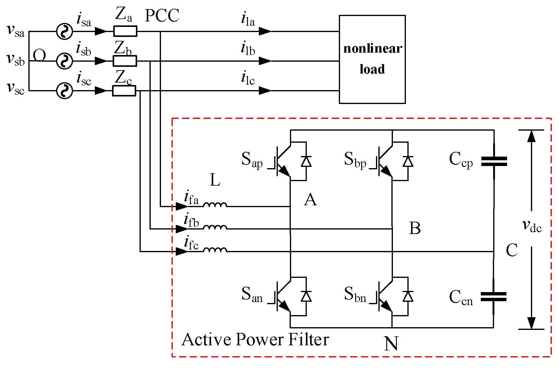
Compared to traditional six-switch APFs, the reduced-switch APF employs fewer switching devices, resulting in reduced switching losses and significantly lower implementation costs. Additionally, it achieves a more compact size and lighter weight, making it better suited for distributed integration in distribution networks to address the increasingly decentralized harmonic sources.
As illustrated in Figure 1, the topology of the three-phase reduced-switch APF features parallel connection between this active power filter and nonlinear loads at the point of common coupling (PCC) associated with the distribution network. In the diagram, usa, usb, usc respectively represent the three-phase source voltages; isa, isb, isc represent the three-phase source currents; ila, ilb, ilc represent the three-phase load currents; ifa, ifb, ifc represent the three-phase filter compensation currents. L denotes the inductor components within the filter, while udc denotes the DC-link capacitor voltage. In the configuration of the reduced-switch APF, the original upper and lower switches (Scp and Scn) in phase C are substituted with two DC capacitors, designated Ccp and Ccn.

2.2. Three-Phase Reduced-Switch APF Control Strategy

In a six-switch active filter, the one-cycle control equation is:
R s i sx = v m ( 1 2 d x ) ,   x = a , b , c
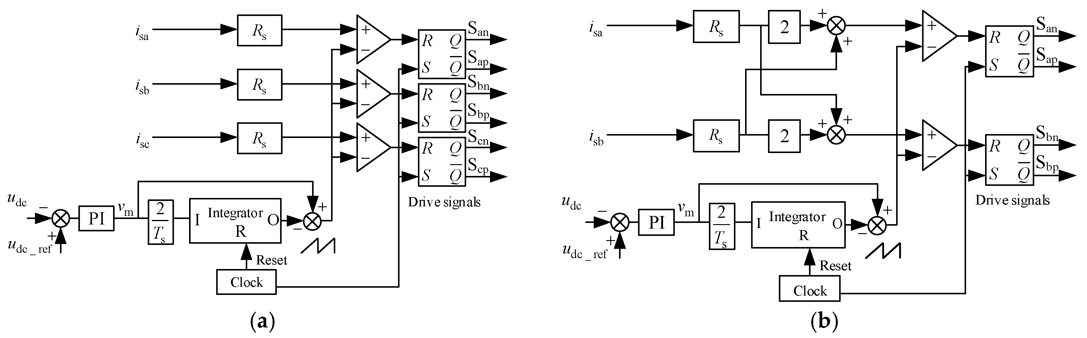
In the equation, vm denotes the output of the DC voltage controller in the control system. The control principle is shown in Figure 2a. In the reduced-switch active power filter, the switches in phase C are replaced by two capacitors and no longer receive control signals. Therefore, the one-cycle control equations for the reduced-switch active power filter need to be modified.
For the three-phase reduced-switch active power filter, the relationship between vAN, vBN, vCN and the duty ratios of each phase switch, as well as the DC-link voltage of the converter, is expressed by the following equation:
v AN = ( 1 d a ) v dc v BN = ( 1 d b ) v dc v CN = 1 / 2 v dc
In the equation, da and db represent the duty cycles of the switching signals for phase A and phase B, respectively.
Based on Equation (2), the relationship between the source voltage, the DC-link voltage, and the switching duty cycles can be derived:
v sa v sb v sc = 2 3 1 3 1 3 1 3 2 3 1 3 1 3 1 3 2 3 1 d an 1 d bn 1 / 2 v dc
Solving Equation (3):
2 v dc 2 v sa + v sb v sa + 2 v sb = 1 2 d an 1 2 d bn
The ideal compensation effect of an active filter can be expressed by the following equation:
v sx = R e i sx , x = a , b , c
In Equation (5), Re denotes the equivalent resistance exhibited externally by all non-resistive components in the power grid. This signifies that after compensation by the active power filter, the APF, nonlinear load, and other non-resistive components in the line interact with one another and ultimately present a pure resistive characteristic, thereby establishing a proportional relationship between the current and the voltage. This ensures that the current remains free from distortion.
By combining Equations (4) and (5), the control equations corresponding to the three-phase reduced-switch active power filter illustrated in Figure 1 can be deduced:
v m 1 2 d an 1 2 d bn = R s 2 1 1 2 i sa i sb
Here, Rs represents the current gain; dan and dbn denote the duty cycles of switches A and B, respectively; vm = Rsvdc/2Re and acts as the output value of the DC-link voltage after PI control is applied. On the basis of the aforementioned equation, a one-cycle control principle of the reduced-switch active filter can be deduced. The source current adjusted by the gain is compared with a sawtooth wave and the output drive signal is produced by means of a flip-flop, as illustrated in Figure 2b.

3. One-Cycle Control Strategy Under Non-Ideal Grid Voltage

In actual power system operation, three-phase voltages do not always maintain ideal waveforms. Voltage waveform distortion and three-phase voltage imbalance frequently occur. To ensure active filters remain effective under non-ideal voltage conditions, this paper analyzes the operational characteristics of a single-cycle-controlled reduced-switch active filter. Based on this analysis, a modified control strategy suitable for non-ideal voltages is proposed.

3.1. The Relationship Between Source Current and Voltage Under One-Cycle Control

Under ideal voltage conditions, active filters maintain a proportional relationship between current and voltage, thereby achieving filtering functionality. However, when three-phase voltages become distorted or unbalanced, traditional one-cycle control methods become ineffective at suppressing harmonics. As a result, an in-depth analysis is needed to investigate the relationship between source current and voltage for one-cycle controlled APFs under non-ideal voltage conditions.
According to the symmetrical component method, any unbalanced three-phase voltage has an equivalent expression as the superposition of positive-sequence, negative-sequence, and zero-sequence voltages. The distortion of voltage waveforms implies the existence of harmonic voltages with diverse frequencies. Therefore, non-ideal voltages can be viewed as the sum of positive-sequence, negative-sequence, and zero-sequence voltages in different frequency bands, which is shown in Equation (7):
v sa = n = 1 ( v sa + n + v sa n + v sa 0 n ) v sb = n = 1 ( v sb + n + v sb n + v sb 0 n ) v sc = n = 1 ( v sc + n + v sc n + v sc 0 n )
In the equation, n denotes the harmonic order of the voltage; v+n, v−n, and v0n represent the positive-sequence, negative-sequence, and zero-sequence voltage components, respectively. Notably, the sum of the three-phase positive-sequence voltages and the sum of the three-phase negative-sequence voltages are both zero, while the sum of the three-phase zero-sequence voltages is non-zero. Under non-ideal conditions, accordingly, the sum of the three-phase source voltages will undergo a change, as shown in Equation (8):
v sa + v sb + v sc = n = 1 ( v sa 0 n + v sb 0 n + v sc 0 n ) = 3 v 0
In the equation, v0 denotes the zero-sequence voltage. Given that the three-phase zero-sequence voltages are in the same phase and have equal magnitudes, the sum of the three-phase zero-sequence voltages equals 3v0. Considering the block diagram of the three-phase reduced-switch active filter introduced previously, since the filtering inductor operates at the switching frequency, which is significantly higher than the 50 Hz power frequency, its impact is negligible. The relationship between the voltages at different points inside the active filter and the source voltage can be deduced:
v sa v AO = v AN + v NO v sb v BO = v BN + v NO v sc v CO = v CN + v NO
The combination of Equations (8) and (9) leads to the derivation of:
v NO = v 0 1 3 ( v AN + v BN + v CN )
Substituting Equation (10) into Equation (9) yields the relationship between the source voltages (vsa, vsb, vsc) and (vAN, vBN, vCN) under non-ideal voltage conditions. This relationship is expressed in matrix form in Equation (11).
v sa v 0 v sb v 0 v sc v 0 = 2 3 1 3 1 3 1 3 2 3 1 3 1 3 1 3 2 3 v AN v BN v CN
By leveraging the relationship between (vAN, vBN, vCN), the duty cycles of each phase switch, and the converter’s DC-link voltage as presented in Combination (2), the correlation between the positive-sequence and negative-sequence voltages of all three phases at each frequency, along with the switch duty cycles and DC-link voltage, can be derived in the following manner:
n = 1 ( v sa + n + v sa n ) n = 1 ( v sb + n + v sb n ) n = 1 ( v sc + n + v sc n ) = 2 3 1 3 1 3 1 3 2 3 1 3 1 3 1 3 2 3 1 d an 1 d bn 1 / 2 v dc
Since there are no power switches in Phase C, the control system does not need to output control signals to Phase C, and thus the relationship regarding the parameters of Phase C in the above equation can be ignored. Solving Equation (12) yields:
1 2 d an 1 2 d bn = 2 v dc 2 1 1 2 n = 1 ( v sa + n + v sa n ) n = 1 ( v sb + n + v sb n )
Substituting Equation (13) into the one-cycle control Equation (6) yields the relationship between the source current and the source voltage after compensation by the active filter under non-ideal voltage conditions, shown in Equation (14):
2 v m v dc R s n = 1 ( v sa + n + v sa n ) n = 1 ( v sb + n + v sb n ) = i sa i sb
Equation (14) only offers the relationship between the phase A and B currents and the source voltage. To obtain the relationship between the phase C current and voltage, it is necessary to retain the phase C current in the control equations. For this reason, Equations (3) and (12) must be solved again.
Based on the derivation process described in the previous section, retaining the phase C current in the control equations yields:
v m 1 2 d an 1 2 d bn = R s i sa i sc i sb i sc
Similarly, solving Equation (12):
1 2 d an 1 2 d bn = 2 v dc n = 1 [ ( v sa + n + v sa n ) ( v sc + n + v sc n ) ] n = 1 [ ( v sb + n + v sb n ) ( v sc + n + v sc n ) ]
Substituting (15) into Equation (16) yields the relationship between the three-phase voltage and current as follows:
i sa i sc i sb i sc = 2 v m R s v dc n = 1 [ ( v sa + n + v sa n ) ( v sc + n + v sc n ) ] n = 1 [ ( v sb + n + v sb n ) ( v sc + n + v sc n ) ]
The preceding discussion has revealed the relationship between the source voltage and source current for phases A and B. When this is combined with the relationship provided in Equation (17), it becomes evident that under non-ideal voltage conditions, the three-phase current of the active filter following compensation is proportional to the sum of the fundamental and harmonic components of the positive-sequence and negative-sequence voltages of the corresponding phase, resulting in a significant reduction in compensation performance.

3.2. Modified One-Cycle Control Equation for Non-Ideal Voltage Conditions

As shown in Section 2.1, under conventional one-cycle control, the source current is proportional to the sum of positive-sequence and negative-sequence voltages and all harmonic components. Therefore, the source current can also be decomposed into positive-sequence and negative-sequence currents of different frequencies, namely:
i sx = n = 1 ( i sx + n + i sx n ) , x = a , b , c
According to Equation (18), Equation (14) can be rewritten as:
n = 1 ( i sx + n + i sx n ) = 2 v m v dc R s n = 1 ( v sx + n + v sx n )
It can be observed from the above equation that, within the network-side current and voltage, the fundamental positive-sequence current bears a proportional relationship to the fundamental positive-sequence voltage, where the proportional ratio is 2vm/vdcRs. The remaining components, excluding the fundamental positive-sequence component, are also proportionally related, as shown in Equation (20):
i sx i sx + 1 = 2 v m v dc R s [ v sx v sx + 1 v 0 ]
Substituting Equation (20) into the conventional one-cycle control equation yields the following modified one-cycle control equation:
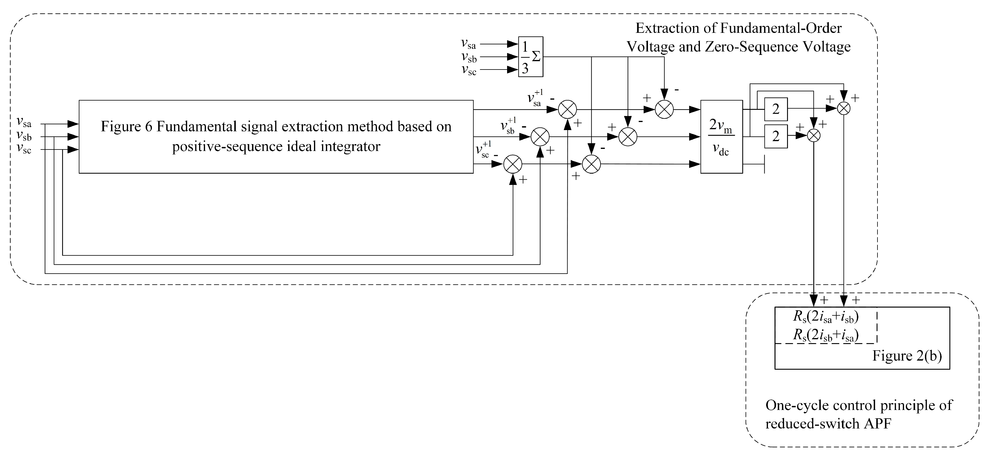
v m 1 2 d an 1 2 d bn = R s 2 1 1 2 i sa + n = 2 ( i sa + n + i sa n ) i sb + n = 2 ( i sb + n + i sb n ) = R s 2 1 1 2 i sa + 1 i sb + 1 + 2 v m v dc 2 1 1 2 v sa v sa + 1 v 0 v sb v sb + 1 v 0
By virtue of the modified one-cycle control equation, fundamental negative-sequence currents and harmonic currents are removed from the source current, and meanwhile, fundamental positive-sequence voltage and zero-sequence voltage are incorporated. This design designates the fundamental positive-sequence current as the active filter’s compensation target, which ensures the compensated current remains three-phase balanced and undistorted even when voltages are non-ideal, leading to a notable improvement in the active filter’s compensation performance.

3.3. Modified One-Cycle Control Strategy Based on Positive Sequence Integrator

The modified one-cycle control equation incorporates fundamental positive-sequence voltage and zero-sequence voltage, with the zero-sequence voltage calculable by summing the three-phase voltages. As for the acquisition of fundamental positive-sequence voltage, this paper employs a fundamental extraction method based on a positive-sequence ideal integrator [25]:
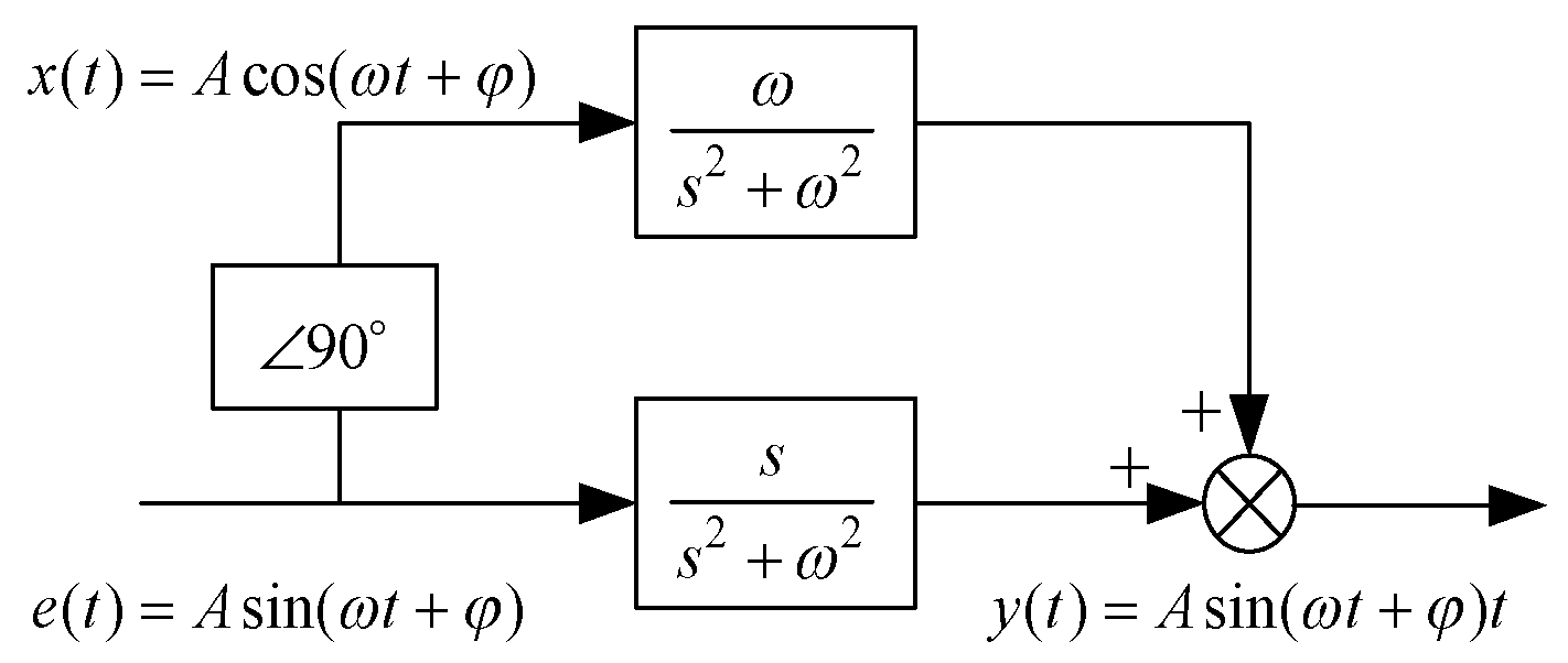
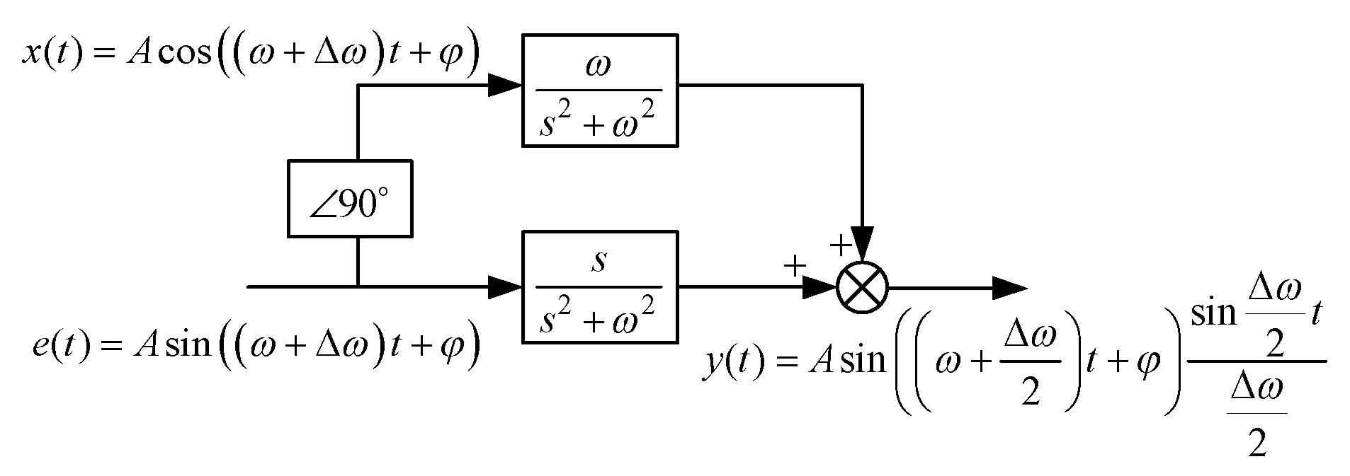
Define a fixed-frequency sinusoidal signal e(t) = Asin(ωt + φ). Its integral signal can be expressed as y(t) = Asin(ωt + φ)t. Applying the Laplace transform to these two signals yields:
E s = A ω cos φ s 2 + ω 2 + A s sin φ s 2 + ω 2
Y s = s s 2 + ω 2 A ω cos φ s 2 + ω 2 + A s sin φ s 2 + ω 2   + ω s 2 + ω 2 A s cos φ s 2 + ω 2 A ω sin φ s 2 + ω 2
Define an auxiliary signal x(t) = Acos(ωt + φ). Perform the Laplace transform on this signal, as shown in the following equation:
X s = A s cos φ s 2 + ω 2 A ω sin φ s 2 + ω 2
Based on Equations (22)–(24), an ideal sine signal integrator can be derived, as shown in Figure 3.
Figure 4 presents the integrator’s output when the input signal has a frequency offset of Δω. As long as Δω is sufficiently small, sin(Δω/2) converges infinitely to Δω/2, which guarantees that the integral function remains effective and the integrator’s output signal keeps a nearly constant value. When Δω becomes large, sin(Δω/2) can no longer be approximated by Δω/2. At this point, the integrator’s output undergoes suppression, and such suppression becomes more significant as Δω increases further. Consequently, an ideal integrator for single-frequency sinusoidal signals only allows sinusoidal signals with frequencies (angular velocities) around ω to pass. For harmonic signals with frequencies that are integer multiples of the fundamental frequency, their output is effectively suppressed after they pass through the ideal integrator.
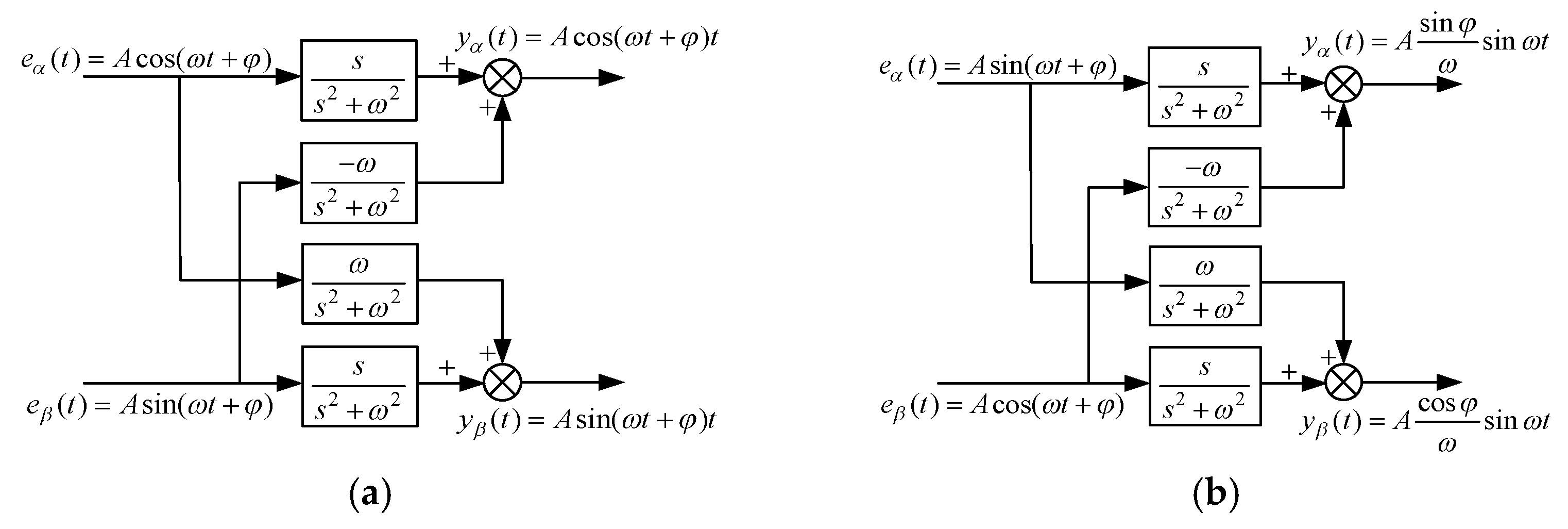
The αβ stationary coordinate system uses α-axis and β-axis signals to construct ideal integrators. For a positive-sequence three-phase system, since the α-axis signal leads the β-axis signal by 90°, two ideal integrators can be combined to form a positive-sequence ideal integrator, as shown in Figure 5a. When negative-sequence signals are situated in the αβ stationary coordinate system, their α-axis signals lag their β-axis signals by 90°; this causes the output response of the positive-sequence ideal integrator to be negligible when the negative-sequence signals pass through it, which is presented in Figure 5b. Therefore, the positive-sequence ideal integrator constructed based on an ideal sine signal integrator permits only the fundamental positive-sequence signal to pass through, while suppressing the entry of negative-sequence signals and all harmonic components.
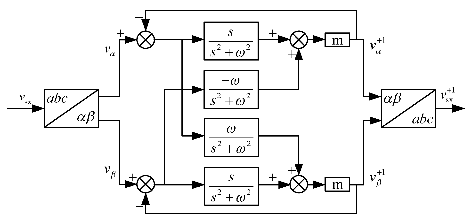
As illustrated in Figure 6, a positive-sequence ideal integrator can be used to extract the fundamental positive-sequence signal. In this figure, vsx (where x = a, b, c) represents the three-phase source voltage, while vsx+1 denotes the three-phase positive-sequence source voltage; vα and vβ stand for the source voltage in the αβ coordinate system, and vα+1 and vβ+1 refer to the fundamental positive-sequence components of the source voltage in the αβ coordinate system. The extraction process proceeds as follows: first, the three-phase source voltage is transformed from the abc coordinate system to the αβ coordinate system. Next, the transformed voltage is passed through a positive-sequence filter built with a positive-sequence ideal integrator; this filter suppresses negative-sequence and harmonic components, ensuring only the fundamental positive-sequence component is allowed to pass. Finally, the output positive-sequence signal is converted back from the αβ coordinate system to the abc coordinate system, enabling the acquisition of the three-phase fundamental positive-sequence voltage. It should be noted that the response speed of the positive-sequence filter is controlled by parameter m: a larger m value leads to a faster response but compromises filtering performance. Thus, the value of m must be set within a reasonable range. In this paper, the value of m is set to 40.
Based on the modified control equation proposed in this section, combined with the aforementioned method for extracting fundamental positive-sequence voltage, the modified one-cycle control schematic shown in Figure 7 can be obtained. The enhanced one-cycle control strategy enables the active filter to maintain effective compensation performance even under source voltage imbalance or distortion conditions.

4. Simulation Validation

To validate the effectiveness of the one-cycle control strategy and modified control method applied to reduced-switch active filters, a reduced-switch active filter model and its control system were established as a numerical simulation model on a simulation platform. The main circuit comprised a three-phase power supply, an uncontrolled rectifier circuit and an unbalanced resistive load, all of which were connected in parallel with the APF at the PCC. The specific simulation parameters are shown in Table 1.
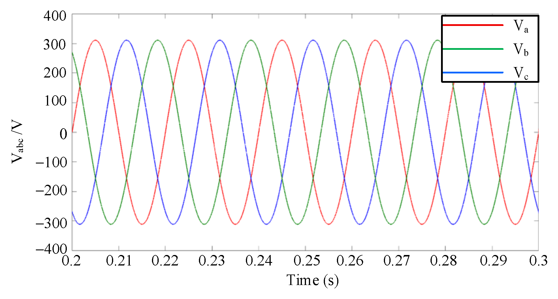
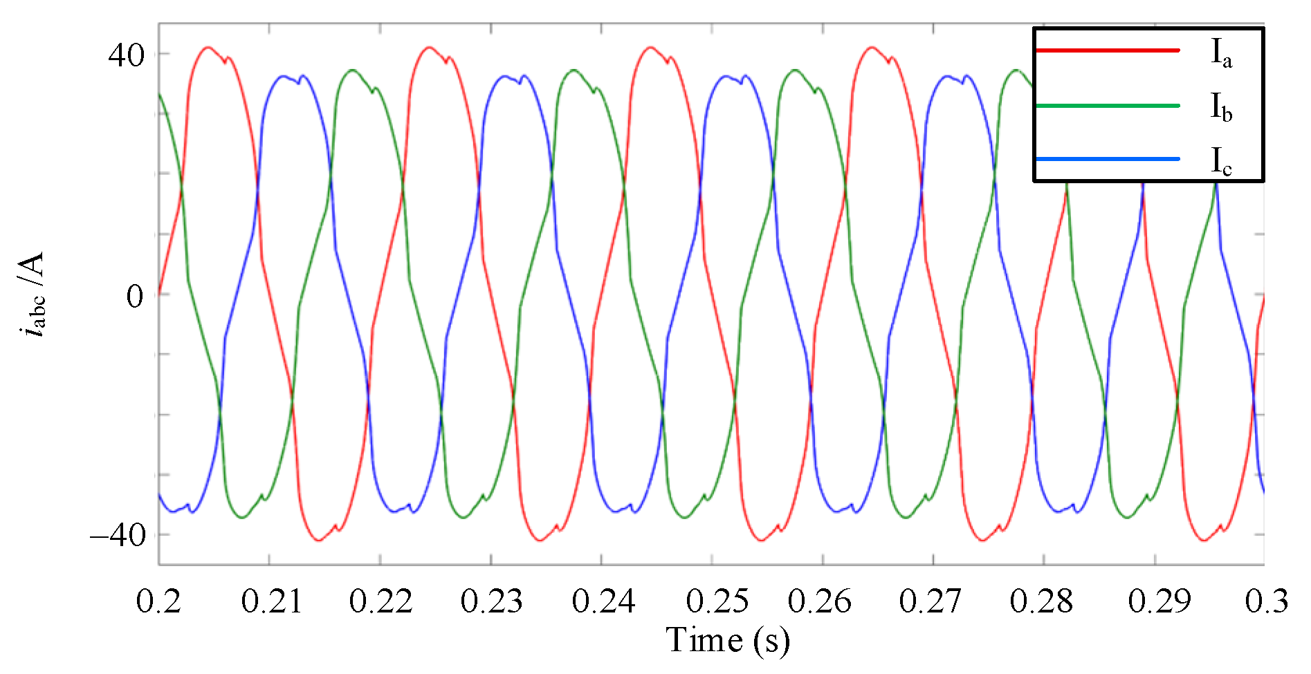
First, the one-cycle controlled reduced-switch active filter was simulated under ideal voltage conditions. The source voltage waveform and the load current waveform without the active filter connected are shown in Figure 8 and Figure 9. Figure 8 presents the ideal voltage waveform, which is free of distortion. In contrast, the waveform of the load current is distorted due to the impact of the non-linear load, with the current harmonic distortion rate reaching 10.18% in this case.
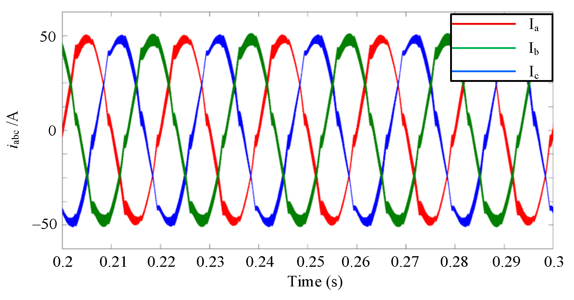
Figure 10 shows the three-phase current waveforms after compensation by the reduced-switch APF. At this point, the source current exhibits a three-phase symmetrical sinusoidal waveform. It can be observed that the one-cycle controlled reduced-switch active filter effectively suppresses harmonic currents. After treatment, the total harmonic distortion (THD) of the current is reduced to 4.13%.
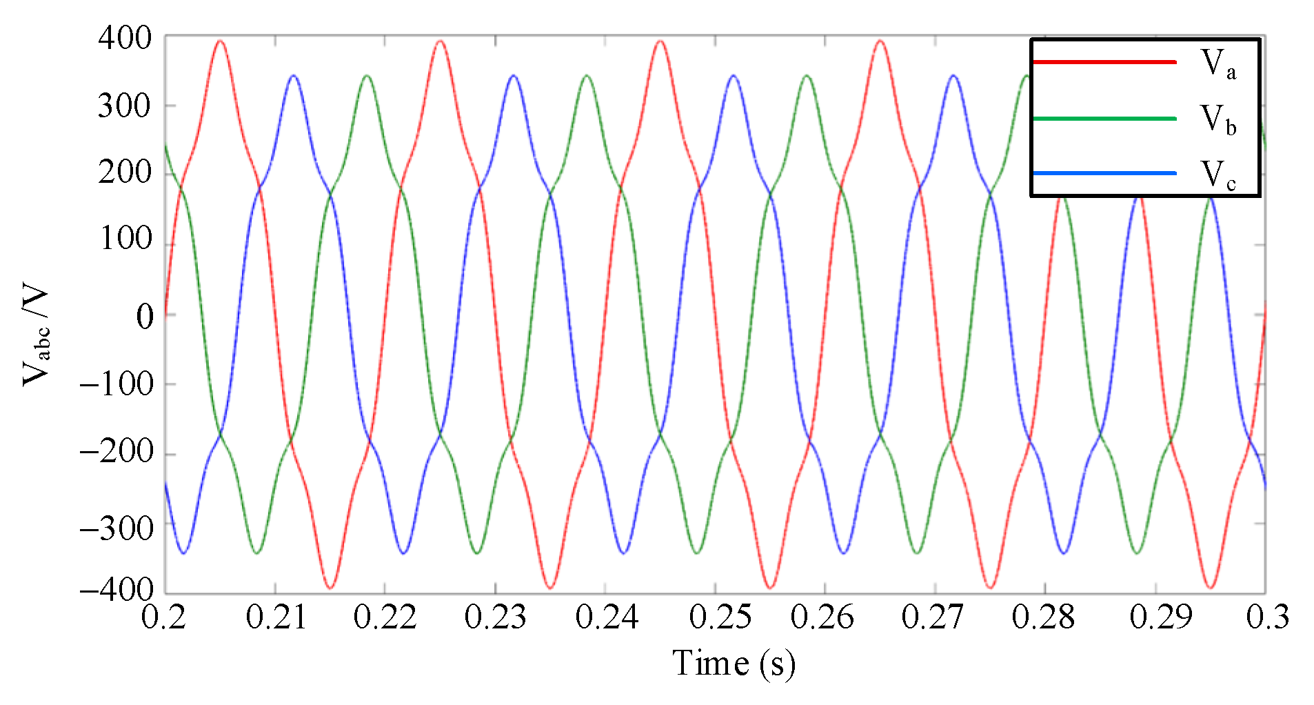
To simulate non-ideal voltage conditions, other voltages were superimposed onto the ideal source voltage. First, a fifth-harmonic component—accounting for 10% of the fundamental voltage amplitude—was added to the source voltage. Subsequently, an extra line-frequency sinusoidal voltage source, which had 20% of the fundamental voltage amplitude, was connected in series with Phase A to simulate three-phase voltage imbalance. The composite source voltage generated in this way and the load current (i.e., the uncompensated source current) are respectively presented in Figure 11 and Figure 12. At this time, the total harmonic distortion (THD) of the supply voltage increases to 8.62%, and the THD of the load current stands at 10.22%.
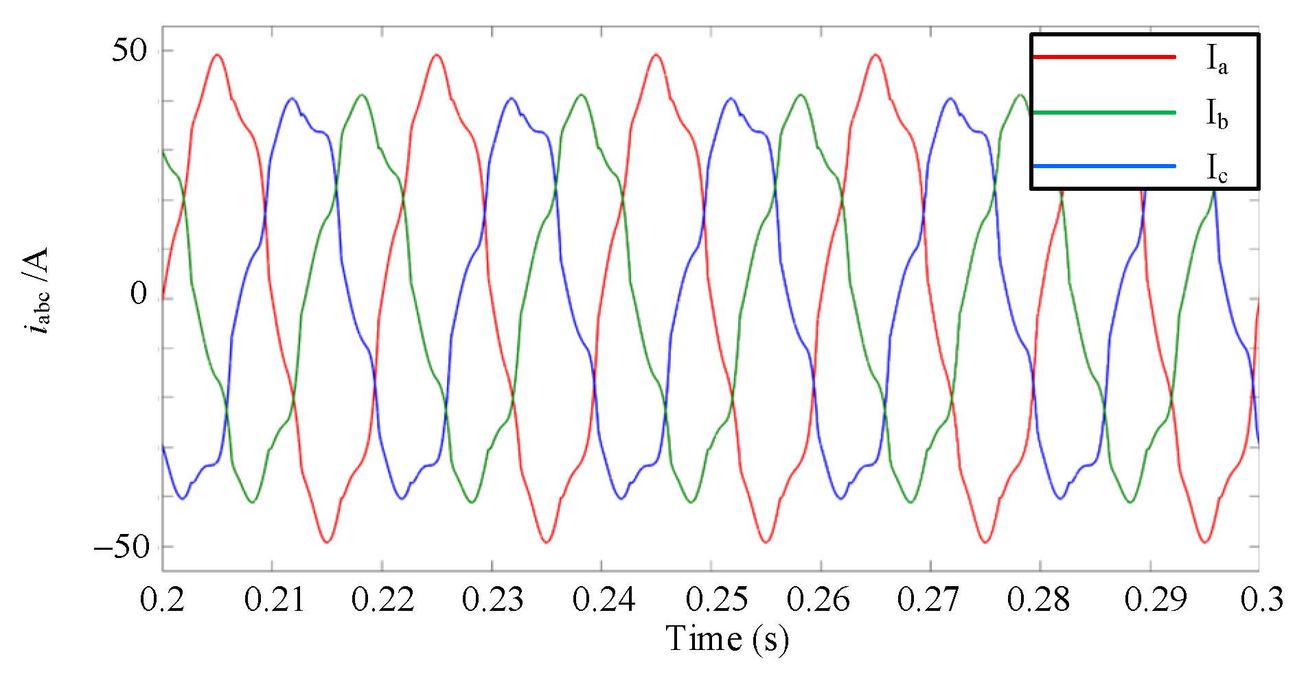
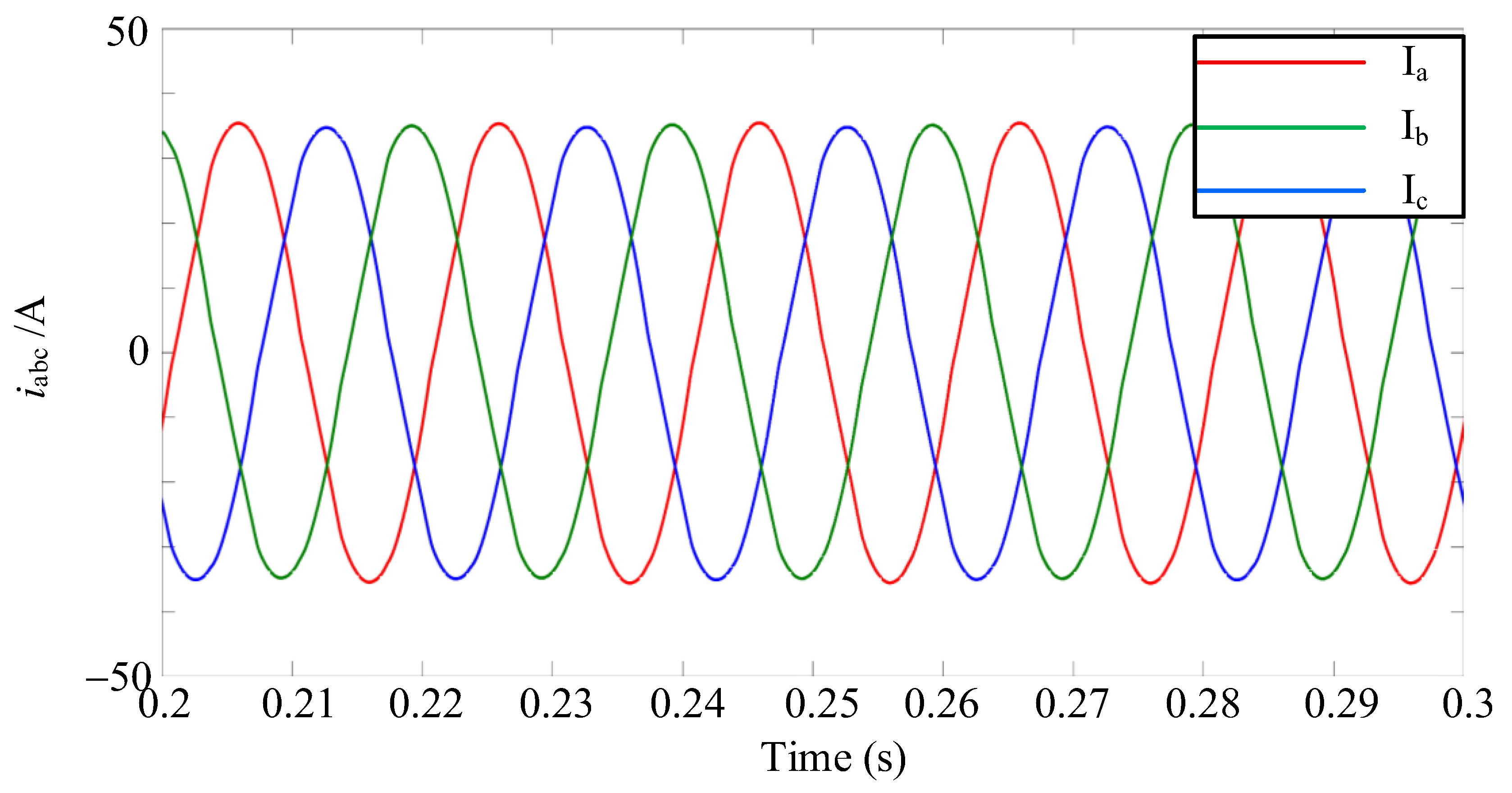
Figure 13 and Figure 14 compare the compensation performance of the traditional one-cycle control method and the modified one-cycle control method proposed in this paper under non-ideal voltage conditions. Figure 13 presents the compensated source current when the traditional one-cycle control method is adopted. It can be observed that the compensated source current fails to form an ideal sinusoidal waveform, and its waveform is similar to the source voltage at that moment. The THD of the current remains at 8.25%, which indicates that the APF (Active Power Filter) adopting the traditional one-cycle control fails to achieve the ideal compensation effect under non-ideal voltage conditions. In contrast, the three-phase source current after applying the modified one-cycle control method is shown in Figure 14. Compared to the traditional one-cycle control method, after incorporating a positive-sequence filter, the compensated source current maintains three-phase balance and exhibits a relatively ideal sinusoidal waveform. At this point, the THD is reduced to 3.79%.
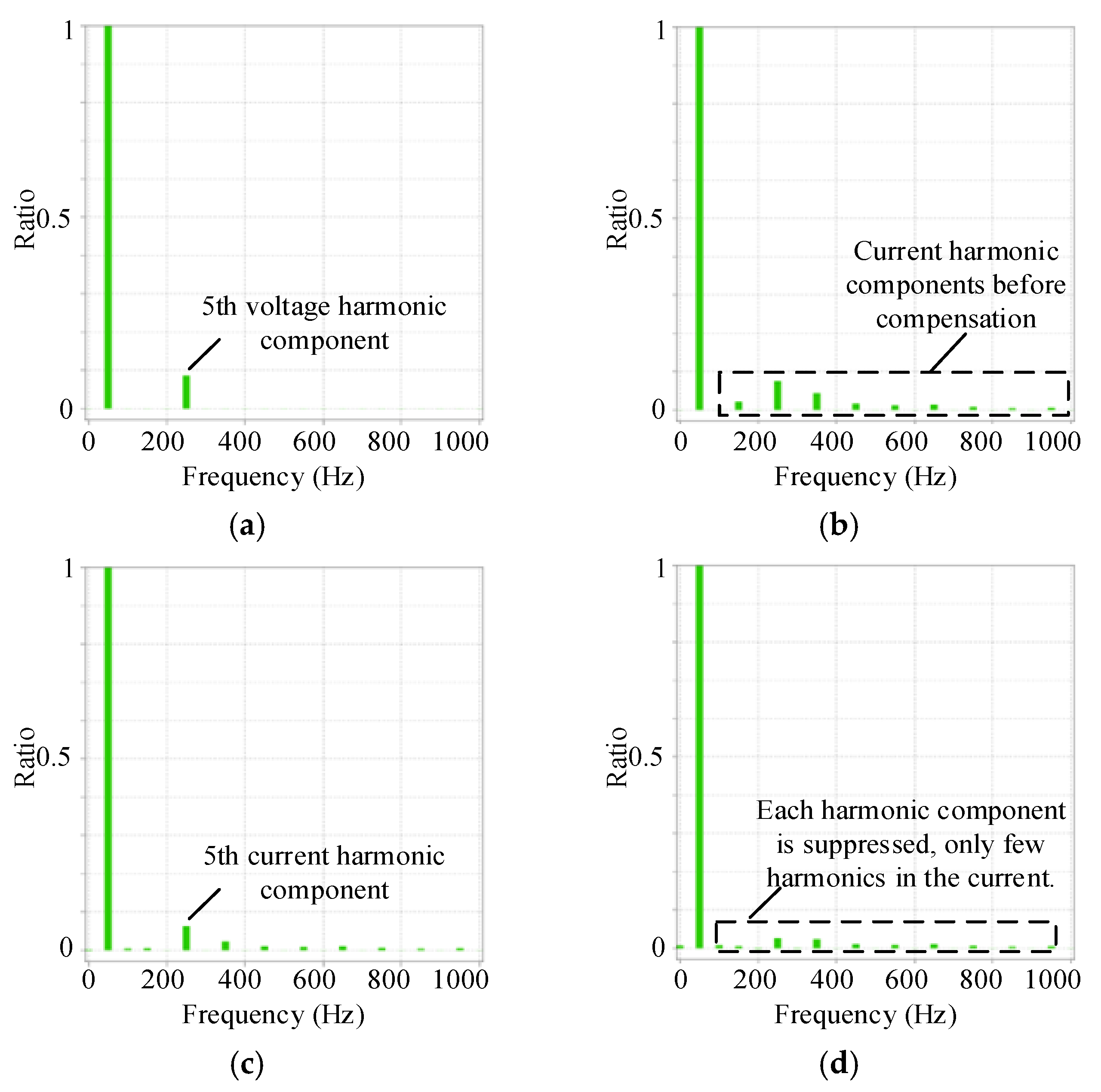
Figure 15 illustrates the spectral characteristics of the compensated source current under different one-cycle control strategies, using Phase A as an example. As shown in Figure 15c, under traditional one-cycle control, all harmonic components of the compensated source current are suppressed, yet substantial fifth-harmonic content remains. This is caused by the voltage harmonics depicted in Figure 15a, consistent with the theoretical analysis discussed earlier. Figure 15d presents the spectrum of the source current under the modified one-cycle control method. Compared with Figure 15c, a significant reduction in fifth-harmonic content is observed, validating the effectiveness of the enhanced one-cycle control.
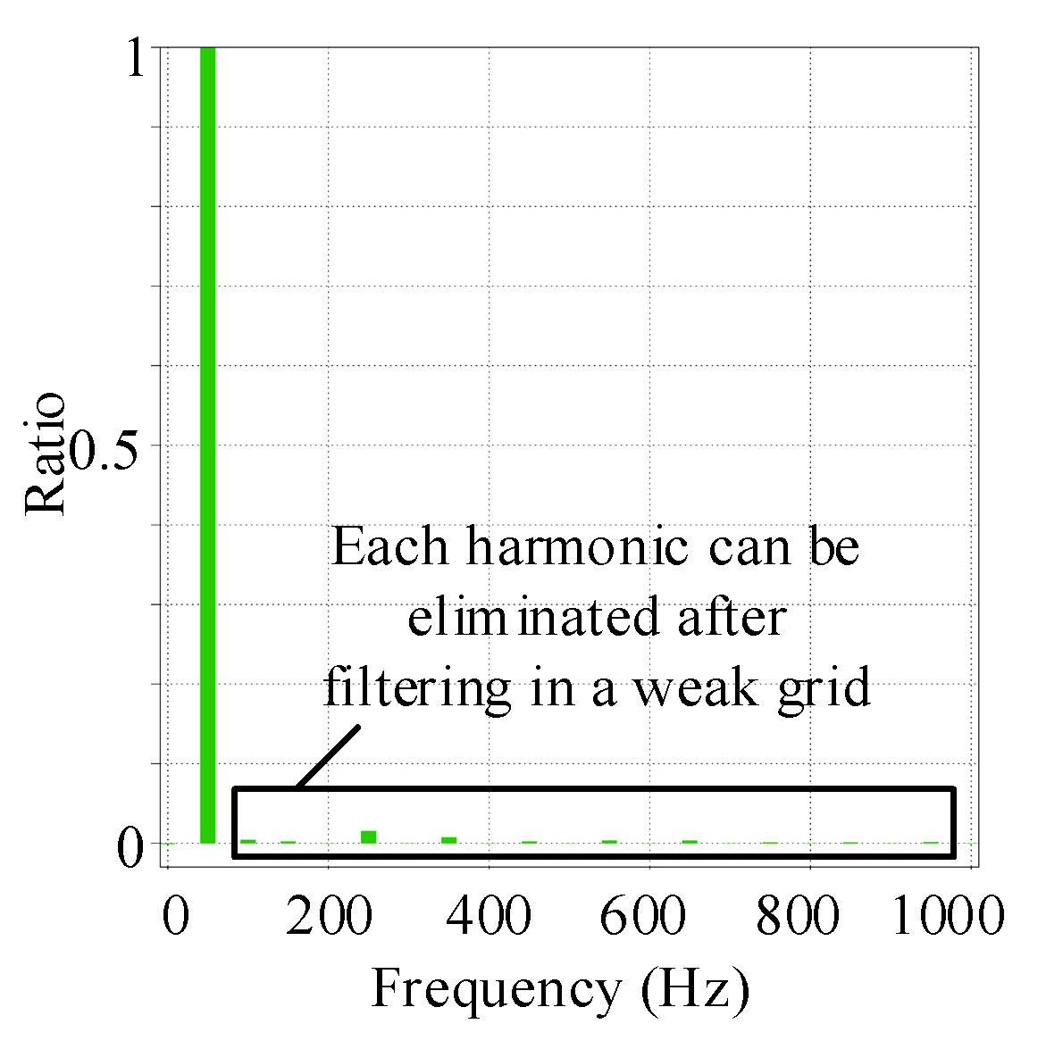
To verify the compensation performance of the proposed control strategy and the reduced-switch APF under weak grid conditions [26,27], this paper modified the simulation parameters to set the grid short-circuit ratio to 2.79. It is generally recognized that a grid with a short-circuit ratio below 3 represents a weak grid. The compensated current and its single-phase spectrum after APF compensation are shown in Figure 16 and Figure 17, respectively. It can be observed that under weak grid conditions, the current compensated by the proposed APF maintains a good sinusoidal waveform, with its harmonic components eliminated, and the total harmonic distortion (THD) can be reduced to 1.71%. The simulation results verify that the proposed control method still exhibits excellent performance under weak grid conditions.
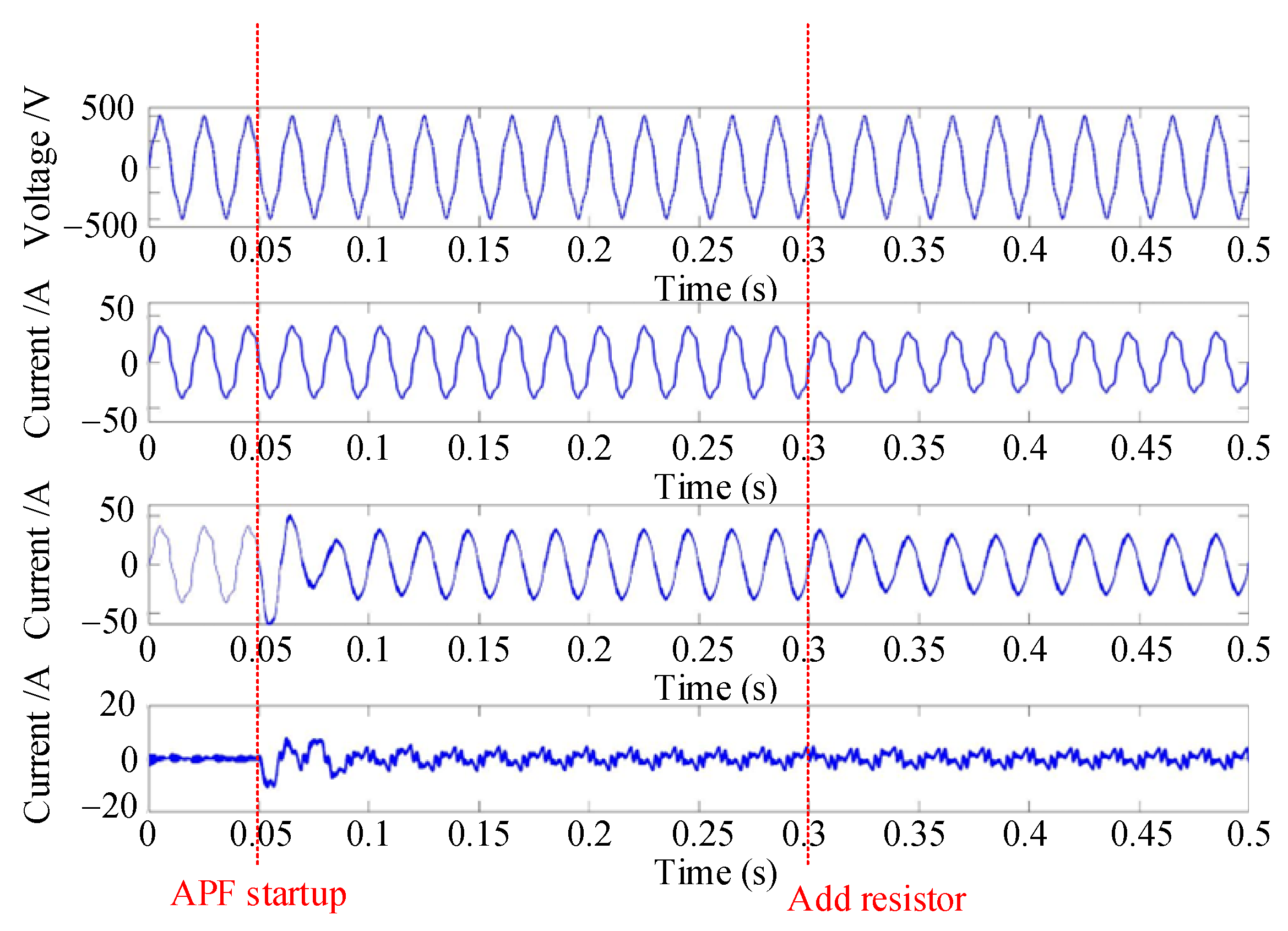
To analyze the dynamic response of the proposed control method, the APF was activated at 0.05 s and a new resistor was added at 0.3 s. Figure 18 shows the changes in phase A signals during this process; from top to bottom: source voltage, load current, source current and compensation current. As shown in Figure 18, when the APF is activated, the source current experiences a certain degree of fluctuation, which stabilizes after approximately 2.5 cycles. When the unbalanced resistor changes, the source current can transition to a new steady state within 2.5 cycles. This demonstrates that the proposed control method has satisfactory robustness and response speed.

5. Experimental Validation and Comparison of Control Strategies

5.1. Experimental Validation

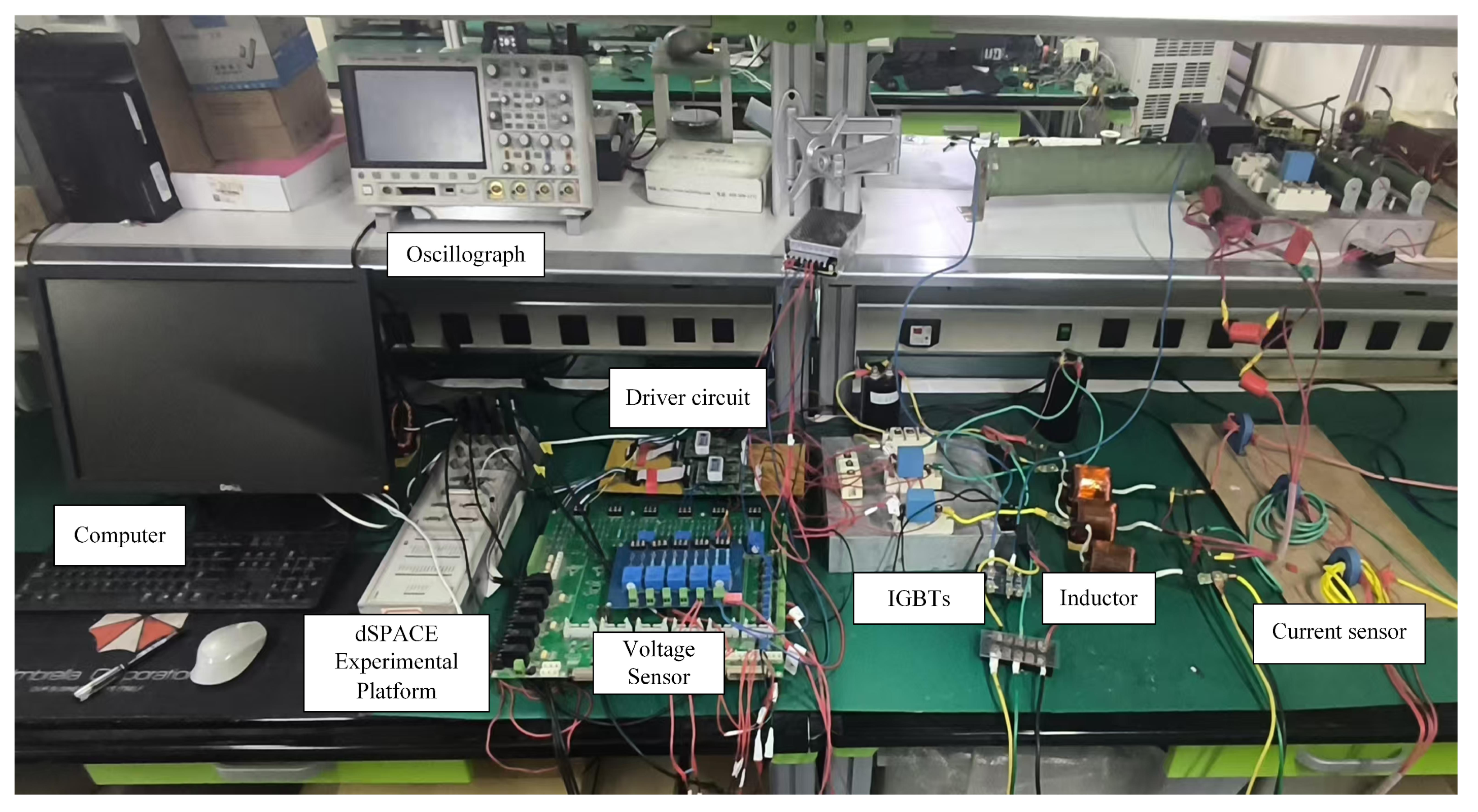
Figure 19 depicts the reduced-switch APF experimental circuit constructed in the laboratory. The control algorithm of the system was implemented on the dSPACE experimental platform, aiming to verify the effectiveness of the proposed modified one-cycle control strategy and assess its compensation capability. Specifically, current sensors and voltage sensors were employed to respectively collect the three-phase currents, three-phase voltages of the system, and DC-link capacitor voltage of the APF. A TX-DE300M2 driver module was employed as the IGBT driver circuit, with the IGBT switching frequency set to 15 kHz during experiments. A three-phase bridge rectifier circuit was used as the nonlinear load to generate harmonics. For the purpose of validating the proposed control strategy under non-ideal voltage conditions, a Chroma 61,511 programmable AC source was chosen to supply power to the main circuit. Experimental parameters are detailed in Table 2.
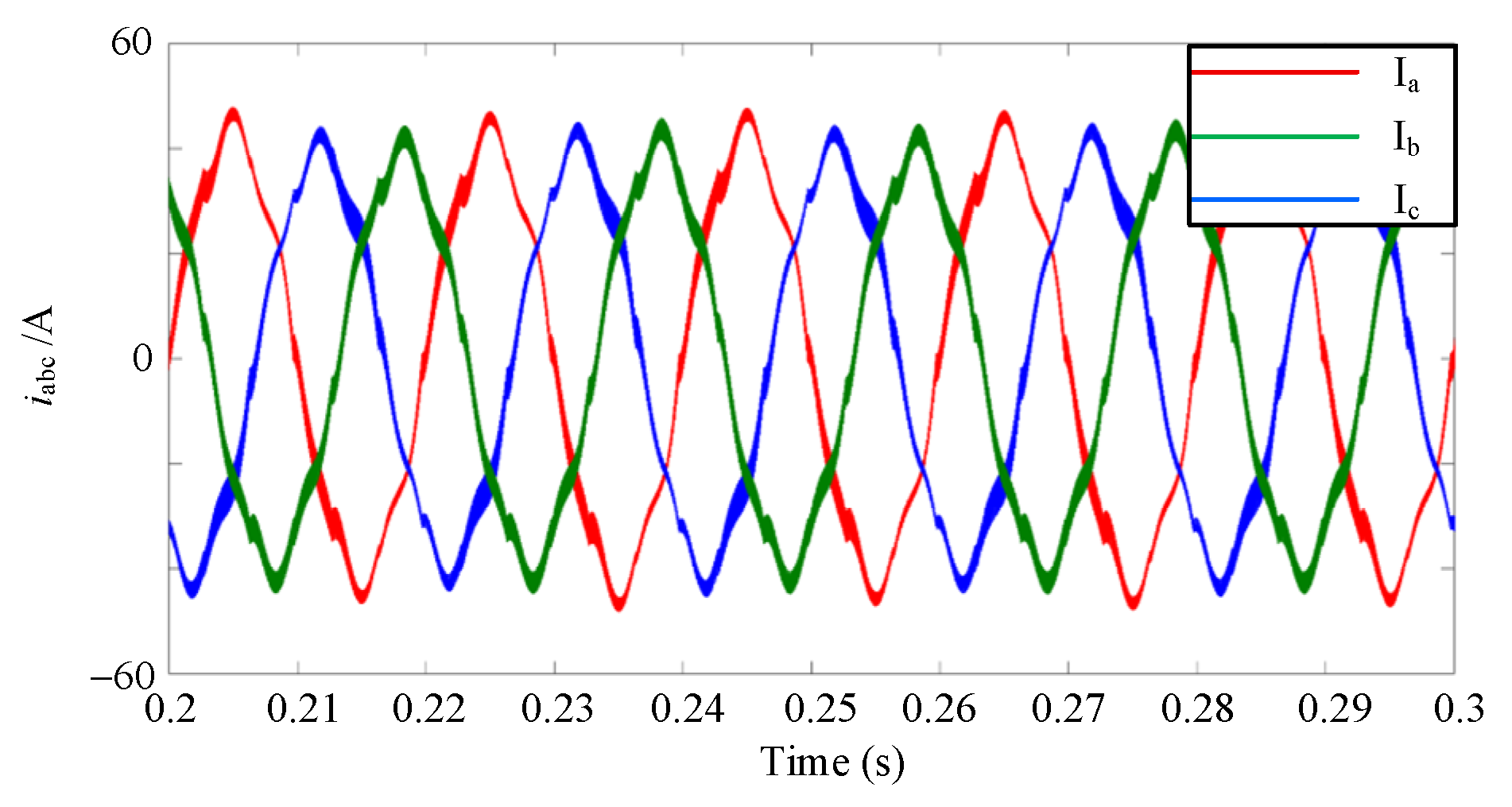
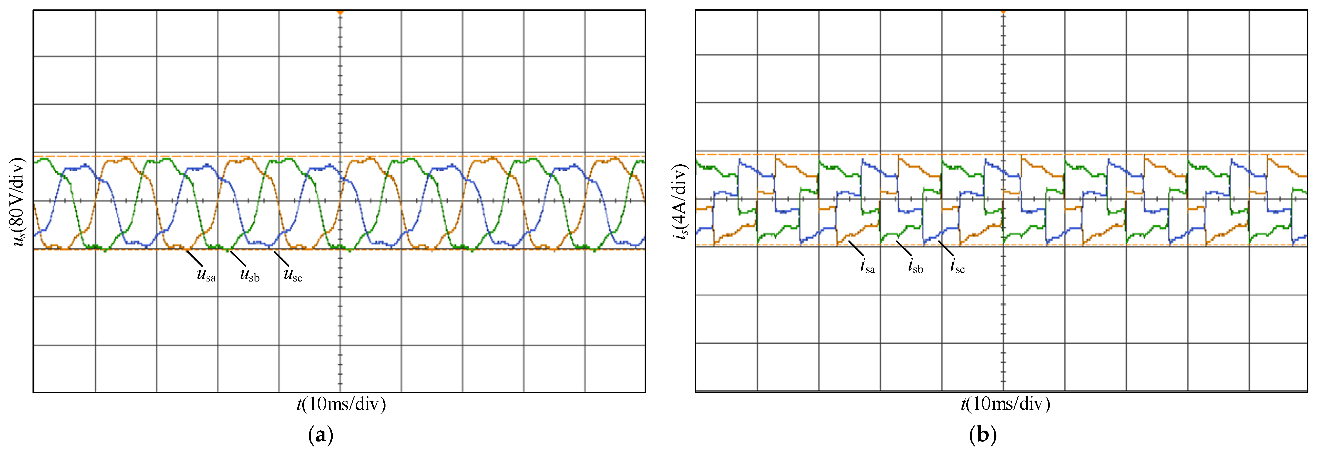
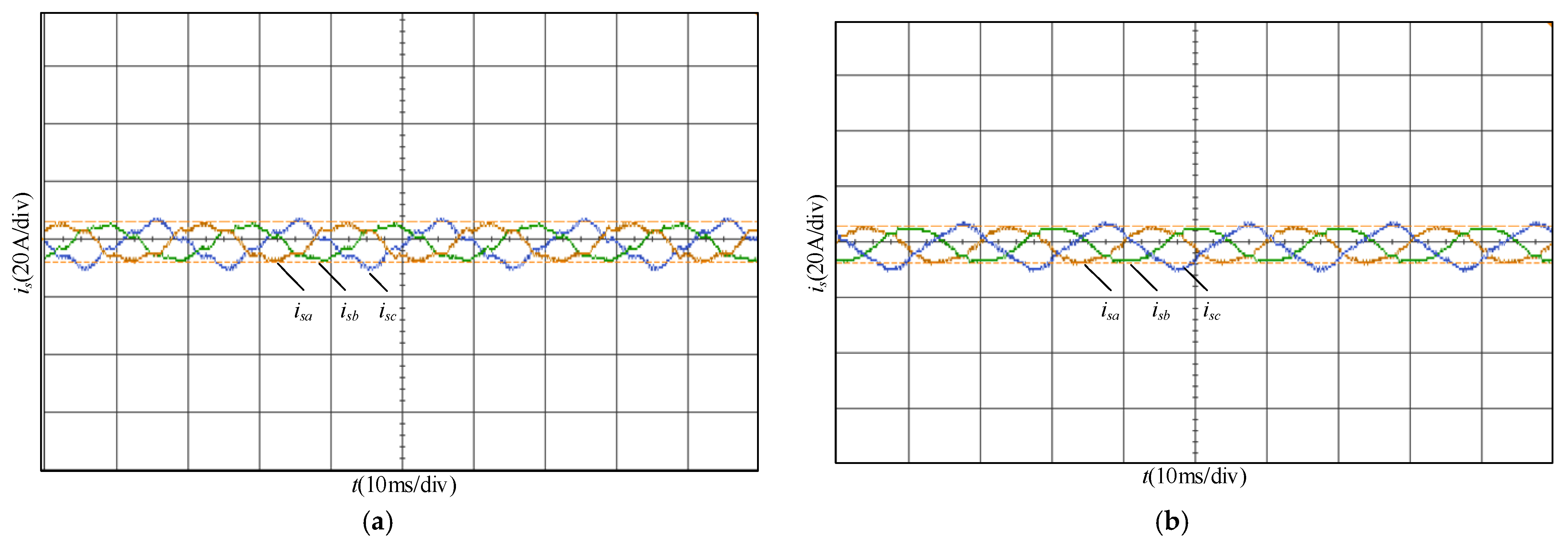
To create the non-ideal voltage conditions required for the experiment, a programmable power supply was used to introduce third harmonic components into its output voltage with an amplitude of 20% of the fundamental component, while setting the voltage of Phase C slightly lower than the other two phases. The adjusted three-phase source voltage and the uncompensated three-phase source current are shown in Figure 20. usa, usb, usc respectively represent the three-phase source voltages, and isa, isb, isc represent the three-phase source currents.
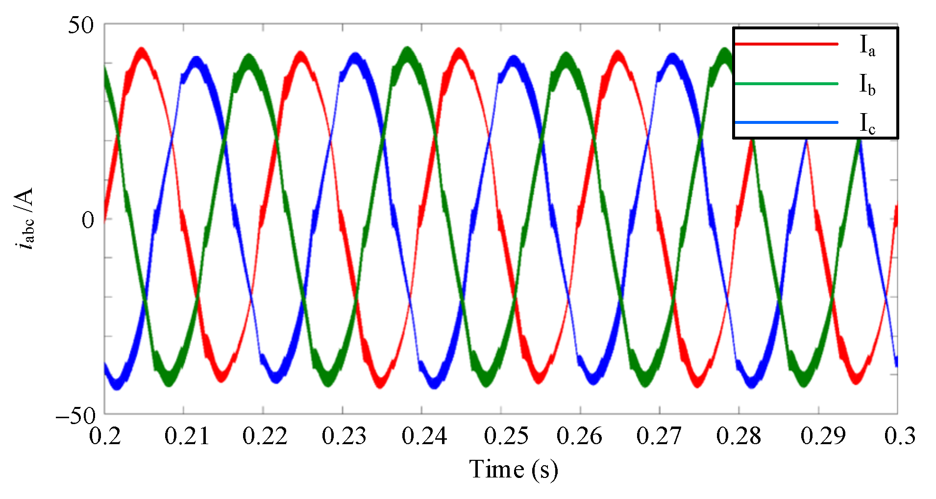
Figure 21 compares the compensation effects of active filters using traditional one-cycle control versus the modified one-cycle control method. The experimental waveform using the traditional one-cycle control method is shown in the figure. As shown in Figure 21a, the compensated source current waveform still exhibits significant distortion. The experimental waveform using the modified one-cycle control method is shown in Figure 21b. Compared to Figure 21a, the current waveform shows a marked improvement.
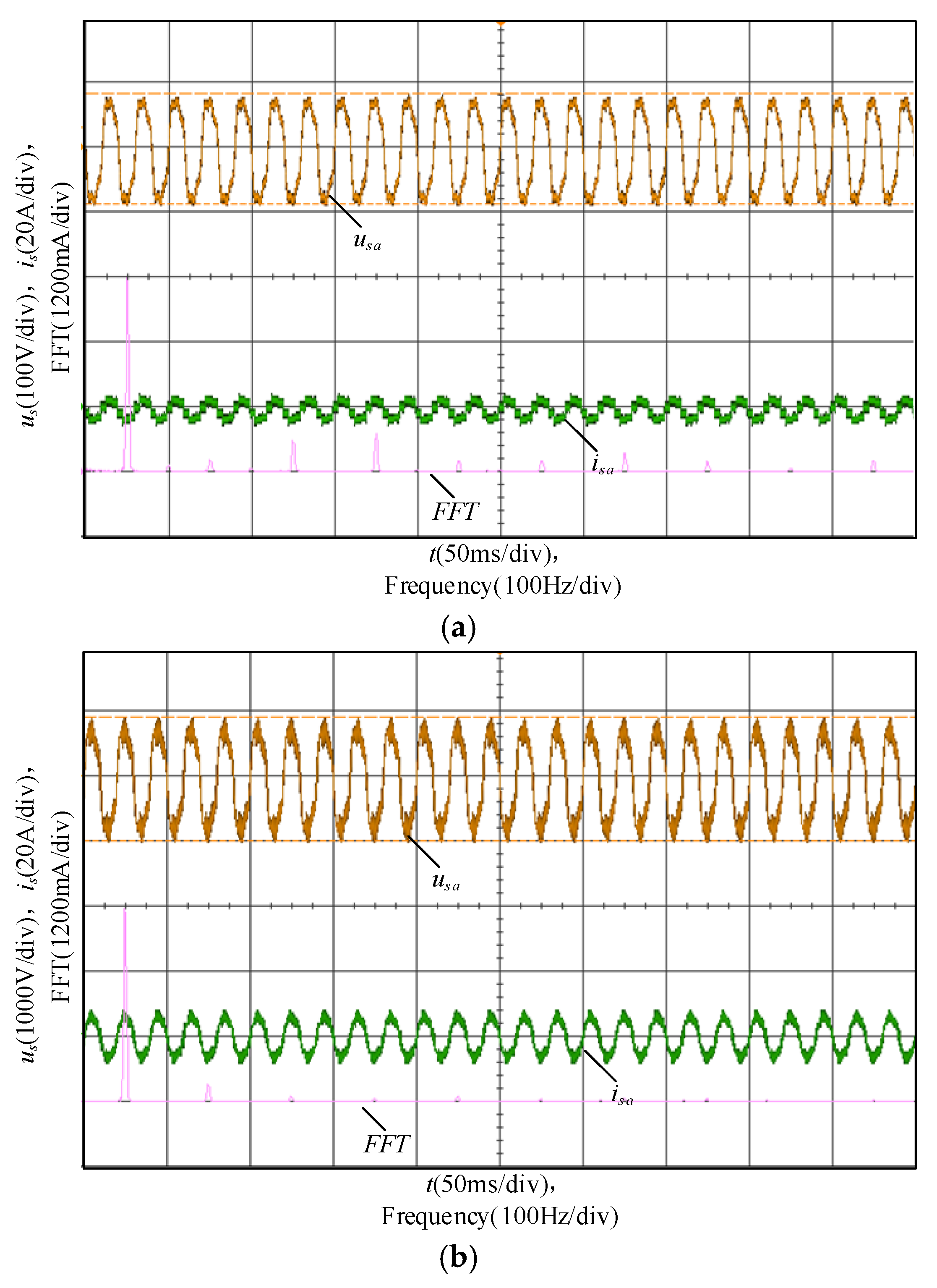
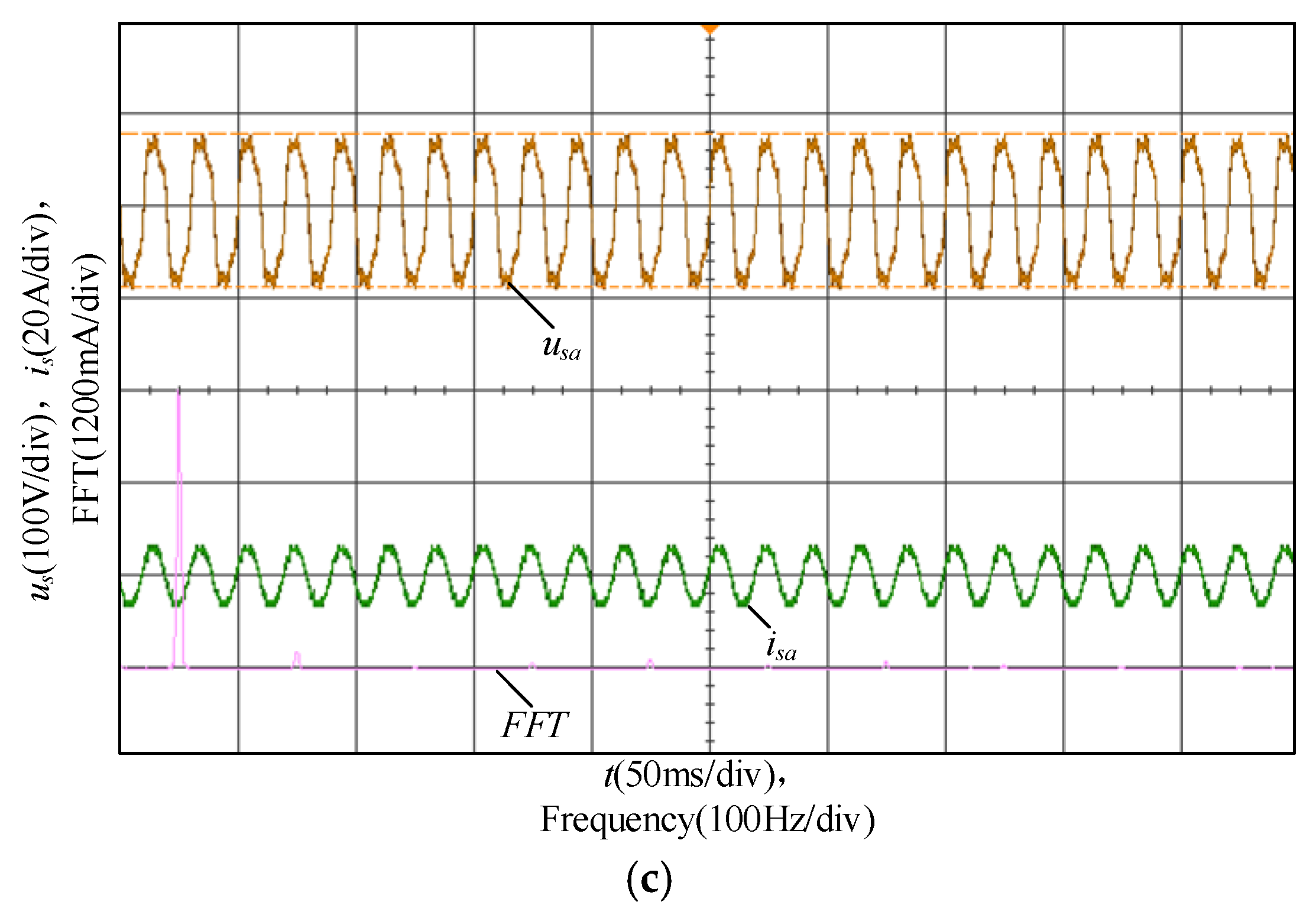
Using the built-in spectrum analysis function of the oscilloscope, the source current spectrum images under different control methods could be obtained, as shown in Figure 22. Comparing the two figures, it is evident that the source current in Figure 22b—after compensation using traditional one-cycle control—suppresses all harmonic components except the third harmonics compared to the uncompensated current in Figure 22a. The most significant reduction occurs at the seventh and ninth harmonics, while the third harmonics remain around 500 mA. This is caused by the third-harmonic components present in the source voltage.
Figure 22c shows the spectrum of the source current after applying the modified one-cycle control. Compared with Figure 22a, the third harmonic component is reduced to about 100 mA, with a reduction rate of approximately 80%, while all other harmonics are suppressed to varying degrees. This demonstrates that the performance of the APF with modified one-cycle control is significantly enhanced under non-ideal source voltage conditions.

5.2. Comparison of Different Control Strategies

To demonstrate the advantages of the modified OCC proposed in this paper for APF control, several commonly used control strategies for active power filters were compared, with the results shown in the following table.
Table 3 compares several control methods in terms of PLL requirement, coordinate transformation requirements, complexity of the control principle, dynamic response speed, engineering application complexity, and application cost. It can be observed from the table that the modified OCC proposed in this paper does not require a PLL or dq coordinate transformation, thus eliminating a large number of trigonometric function operations. Inheriting the advantages of traditional one-cycle control (OCC), such as a simple control principle, fast dynamic response, and low application cost, the proposed method is easy to implement in engineering applications. Moreover, it enables the OCC-based APF to maintain excellent operational performance under non-ideal voltage conditions at a low implementation cost.

6. Conclusions

This paper proposes a reduced-switch APF employing a modified one-cycle control strategy. It derives in detail the modified one-cycle control equations corresponding to the reduced number of APF switching devices. This control strategy eliminates the need for a phase-locked loop and avoids adding complex current controllers. While maintaining the simplicity of traditional one-cycle control methods, it significantly improves the harmonic compensation performance of the APF under non-ideal voltage conditions. In summary, the proposed reduced-switch APF and its enhanced one-cycle control scheme ensure excellent harmonic compensation performance while significantly reducing hardware costs and switching losses. This facilitates the large-scale deployment of APFs in distribution networks. A laboratory experiment circuit for the reduced-switch APF with one-cycle control was constructed using dSPACE. The experiment validated the effectiveness of the proposed modified one-cycle control method. In the experiments, the third harmonic content was reduced from approximately 400 mA to less than 200 mA, with a reduction of about 50%, and the remaining harmonic components were essentially reduced to zero, demonstrating that the enhanced one-cycle control achieves excellent compensation performance and enables the application of reduced-switch active filters under non-ideal voltage conditions.

Author Contributions

Conceptualization, H.P. and L.W. (Lei Wang); methodology, W.Z. (Wenna Zhang); software, H.P.; validation, H.P. and W.Z. (Wenna Zhang); formal analysis, W.Z. (Wenna Zhang); investigation, W.Z. (Wenna Zhang); resources, W.Z. (Wenqiang Zhang); data curation, L.W. (Lidong Wang); writing—original draft preparation, H.P. and L.W. (Lei Wang); writing—review and editing, H.P.; visualization, L.W. (Lidong Wang); supervision, W.Z. (Wenqiang Zhang); project administration, W.Z. (Wenqiang Zhang); funding acquisition, W.Z. (Wenna Zhang). All authors have read and agreed to the published version of the manuscript.

Funding

This research was funded by the Science and Technology Project of State Grid Shanxi Electric Power Company “Research on Collaborative Optimization Technology for Flexible Loads Participation in Distribution Network Voltage Regulation and Harmonic Suppression”, grant number 5205M0250005.

Data Availability Statement

The data presented in this study are available on request from the corresponding author (privacy).

Conflicts of Interest

Author Honglan Pei, Wenna Zhang and Lidong Wang are employed by the Yuncheng Electric Power Supply Company of State Grid Shanxi Electric Power Company. Author Wenqiang Zhang is employed by Taiyuan Electric Power Supply Company of State Grid Shanxi Electric Power Company. The remaining author declares that the research was conducted in the absence of any commercial or financial relationships that could be construed as a potential conflict of interest. The authors declare that this study received funding from the State Grid Shanxi Electric Power Company. The funder was not involved in the study design, collection, analysis, interpretation of data, the writing of this article or the decision to submit it for publication.

References

  1. Li, J.; He, Y.; Xu, L.; Liu, J. Design of Hybrid Power Filters for Supraharmonics Suppression in Power Electronics Dominated Power Systems. IEEE J. Emerg. Sel. Top. Power Electron. 2024, 12, 2163–2175. [Google Scholar] [CrossRef]
  2. Gong, C.; Lam, C.-S. Model and Data Hybrid Reinforcement Learning for Optimal Voltage-Current Control of Hybrid Active Power Filter. IEEE Trans. Power Electron. 2025, 40, 12845–12857. [Google Scholar] [CrossRef]
  3. Zhang, Z.; Yi, H.; Li, Y.; Jiang, X.; Wang, Z.; Zhuo, F. A Novel Decentralized Droop Control Scheme for Multiparalleled APFs with Grid Current Detected. IEEE Trans. Power Electron. 2025, 40, 5922–5938. [Google Scholar] [CrossRef]
  4. Rai, K.B.; Kumar, N.; Singh, A. Three-Phase Grid Connected Shunt Active Power Filter Based on Adaptive Q-LMF Control Technique. IEEE Trans. Power Electron. 2024, 39, 10216–10225. [Google Scholar] [CrossRef]
  5. Jiang, X.; Yi, H.; Zhuo, F.; Li, Y. A Stabilization Strategy Based on Grid Current Feedforward for the Harmonic Oscillation of APF System. IEEE J. Emerg. Sel. Top. Power Electron. 2024, 12, 2116–2129. [Google Scholar] [CrossRef]
  6. Salmeron, P.; Herrera, R.S. Distorted and unbalanced systems compensation within instantaneous reactive power framework. IEEE Trans. Power Deliv. 2006, 21, 1655–1662. [Google Scholar] [CrossRef]
  7. Serra, F.M.; Montoya, O.D.; De Angelo, C.H.; Forchetti, D.G. On The Use of the P-Q Theory for Harmonic Current Cancellation with Shunt Active Filters. Electr. Electron. 2019, 17, 262–269. [Google Scholar] [CrossRef]
  8. Newman, M.J.; Zmood, D.N.; Holmes, D.G. Stationary frame harmonic reference generation for active filter systems. In Proceedings of the APEC. Seventeenth Annual IEEE Applied Power Electronics Conference and Exposition (Cat. No.02CH37335), Dallas, TX, USA, 10–14 March 2002; pp. 1054–1060. [Google Scholar] [CrossRef]
  9. Kesler, M.; Ozdemir, E. Synchronous-Reference-Frame-Based Control Method for UPQC Under Unbalanced and Distorted Load Conditions. IEEE Trans. Ind. Electron. 2011, 58, 3967–3975. [Google Scholar] [CrossRef]
  10. Su, T.; Yang, M.; Jin, T.; Flesch, R.C.C. Power harmonic and inter harmonic detection method in renewable power based on Nuttall double-window all-phase FFT algorithm. IET Renew. Power Gener. 2018, 12, 953–961. [Google Scholar] [CrossRef]
  11. Yang, B.; Dai, K.; Yang, C.; Luo, H.; He, K.; Dai, Z. Improvement of Recursive DFT for APF With Higher Switching Frequency to Suppress Wideband Harmonics. IEEE Access 2021, 9, 144300–144312. [Google Scholar] [CrossRef]
  12. Lascu, C.; Asiminoaei, L.; Boldea, I.; Blaabjerg, F. Frequency Response Analysis of Current Controllers for Selective Harmonic Compensation in Active Power Filters. IEEE Trans. Ind. Electron. 2009, 56, 337–347. [Google Scholar] [CrossRef]
  13. Pereira, L.F.A.; Flores, J.V.; Bonan, G.; Coutinho, D.F.; da Silva, J.M.G. Multiple Resonant Controllers for Uninterruptible Power Supplies—A Systematic Robust Control Design Approach. IEEE Trans. Ind. Electron. 2014, 61, 1528–1538. [Google Scholar] [CrossRef]
  14. Pandove, G.; Singh, M. Robust Repetitive Control Design for a Three-Phase Four Wire Shunt Active Power Filter. IEEE Trans. Ind. Inform. 2019, 15, 2810–2818. [Google Scholar] [CrossRef]
  15. Kumar, P.; Mahajan, A. Soft Computing Techniques for the Control of an Active Power Filter. IEEE Trans. Power Deliv. 2009, 24, 452–461. [Google Scholar] [CrossRef]
  16. Cirrincione, M.; Pucci, M.; Vitale, G.; Miraoui, A. Current Harmonic Compensation by a Single-Phase Shunt Active Power Filter Controlled by Adaptive Neural Filtering. IEEE Trans. Ind. Electron. 2009, 56, 3128–3143. [Google Scholar] [CrossRef]
  17. Hirve, S.; Chatterjee, K.; Fernandes, B.G.; Imayavaramban, M.; Dwari, S. PLL-Less Active Power Filter Based on One-Cycle Control for Compensating Unbalanced Loads in Three-Phase Four-Wire System. IEEE Trans. Power Deliv. 2007, 22, 2457–2465. [Google Scholar] [CrossRef]
  18. Wang, L.; Han, X.; Ren, C.; Yang, Y.; Wang, P. A Modified One-Cycle-Control-Based Active Power Filter for Harmonic Compensation. IEEE Trans. Ind. Electron. 2018, 65, 738–748. [Google Scholar] [CrossRef]
  19. Qiao, C.; Smedley, K.M.; Maddaleno, F. A single-phase active power filter with one-cycle control under unipolar operation. IEEE Trans. Circuits Syst. I Regul. Pap. 2004, 51, 1623–1630. [Google Scholar] [CrossRef]
  20. Jin, T.; Smedley, K.M. Operation of One-Cycle Controlled Three-Phase Active Power Filter with Unbalanced Source and Load. IEEE Trans. Power Electron. 2006, 21, 1403–1412. [Google Scholar] [CrossRef]
  21. Chen, X.; Shi, M.; Zhou, J.; Zuo, W.; Chen, Y.; Wen, J. Consensus-Based Distributed Control for Photovoltaic-Battery Units in a DC Microgrid. IEEE Trans. Ind. Electron. 2019, 66, 7778–7787. [Google Scholar] [CrossRef]
  22. Qiao, C.; Jin, T.; Smedley, K.M. One-cycle control of three-phase active power filter with vector operation. IEEE Trans. Ind. Electron. 2004, 51, 455–463. [Google Scholar] [CrossRef]
  23. Qiao, C.; Smedley, K.M. Three-phase bipolar mode active power filters. IEEE Trans. Ind. Appl. 2002, 38, 149–158. [Google Scholar] [CrossRef]
  24. Sreeraj, E.S.; Prejith, E.K.; Chatterjee, K.; Bandyopadhyay, S. An Active Harmonic Filter Based on One-Cycle Control. IEEE Trans. Ind. Electron. 2014, 61, 3799–3809. [Google Scholar] [CrossRef]
  25. Yuan, X.; Merk, W.; Stemmler, H.; Allmeling, J. Stationary-frame generalized integrators for current control of active power filters with zero steady-state error for current harmonics of concern under unbalanced and distorted operating conditions. IEEE Trans. Ind. Appl. 2002, 38, 523–532. [Google Scholar] [CrossRef]
  26. Mohammed, N.; Ravanji, M.H.; Zhou, W.; Bahrani, B. Online Grid Impedance Estimation-Based Adaptive Control of Virtual Synchronous Generators Considering Strong and Weak Grid Conditions. IEEE Trans. Sustain. Energy 2023, 14, 673–687. [Google Scholar] [CrossRef]
  27. Xu, J.; Zhong, J.; Kang, J.; Dong, W.; Xie, S. Stability Analysis and Robust Parameter Design of DC-Voltage Loop for Three-Phase Grid-Connected PV Inverter Under Weak Grid Condition. IEEE Trans. Ind. Electron. 2024, 71, 3776–3787. [Google Scholar] [CrossRef]
Figure 1. Three-phase reduced-switch shunt APF.
Processes 14 00733 g001
Figure 2. The principles of OCC for APFs with different numbers of switches: (a) One-cycle control principle of six-switch APF; (b) One-cycle control principle of reduced-switch APF.
Processes 14 00733 g002
Figure 3. An ideal integrator for a single sinusoidal signal.
Processes 14 00733 g003
Figure 4. Sinusoidal signal with frequency deviation of Δω passing through the ideal integrator.
Processes 14 00733 g004
Figure 5. Output response of positive-sequence ideal integrators to signals with different phase sequences: (a) Output response of a positive-sequence ideal integrator to a positive-sequence signal; (b) Output response of a positive-sequence ideal integrator to negative-sequence signals.
Processes 14 00733 g005
Figure 6. Fundamental signal extraction method based on positive-sequence ideal integrator.
Processes 14 00733 g006
Figure 7. Schematic of OCC adapted to non-ideal voltage conditions.
Processes 14 00733 g007
Figure 8. Three-phase source voltage waveform.
Processes 14 00733 g008
Figure 9. Three-phase load current waveform at ideal voltage.
Processes 14 00733 g009
Figure 10. Three-phase source currents.
Processes 14 00733 g010
Figure 11. Source voltage waveform containing harmonics and exhibiting three-phase imbalance.
Processes 14 00733 g011
Figure 12. Three-phase load current waveform under non-ideal voltage conditions.
Processes 14 00733 g012
Figure 13. Three-phase source current waveform under traditional one-cycle control.
Processes 14 00733 g013
Figure 14. Modified three-phase source current waveform under one-cycle control.
Processes 14 00733 g014
Figure 15. Single-phase source voltage, load current and source current frequency spectrum with different control strategies: (a) Single-phase voltage spectrum; (b) Single-phase load current spectrum; (c) Traditional one-cycle control of single-phase source current spectrum; (d) Modified single-phase source current spectrum control.
Processes 14 00733 g015
Figure 16. Three-phase source current waveforms under weak grid conditions.
Processes 14 00733 g016
Figure 17. Spectrum of single-phase source current under weak grid conditions.
Processes 14 00733 g017
Figure 18. Dynamic response of proposed control method.
Processes 14 00733 g018
Figure 19. Modified OCC APF experimental circuit based on dSPACE.
Processes 14 00733 g019
Figure 20. Three-phase source voltages and load currents at non-ideal voltage: (a) Three-phase asymmetrical source voltage waveform containing harmonics; (b) Three-phase load current waveform under non-ideal voltage conditions.
Processes 14 00733 g020
Figure 21. Three-phase source currents and load currents after harmonic compensation: (a) Three-phase load current waveform after harmonic compensation; (b) Three-phase source current waveform after harmonic compensation.
Processes 14 00733 g021
Figure 22. Spectrum analysis: (a) Waveform and spectrum of Phase A load current; (b) Phase A source current waveform and spectrum under traditional one-cycle control; (c) current waveform and spectrum of the Phase A source under modified one-cycle control.
Processes 14 00733 g022aProcesses 14 00733 g022b
Table 1. Parameters of simulation.
ProjectSimulation Parameters
Source voltage220 V
Operating frequency50 Hz
System impedance0.2 + 0.01 Ω
AC inductor2 mH
DC capacitor1500 μF
DC reference voltage750 V
Switching frequency15 kHz
Voltage Loop PI ParametersKp = 0.1, Ki = 20
LoadRectifier load3 mH, 20 Ω
Unbalanced resistor15 Ω/20 Ω/20 Ω
Table 2. Parameters of experiment.
ProjectExperimental Parameters
Source voltage60 V
Operating frequency50 Hz
AC inductor1 mH
DC capacitor3700 μF
DC reference voltage175 V
Switching frequency15 kHz
Voltage loop PI parametersKp = 0.05, Ki = 0.05
Rectifier load3 mH, 20 Ω
Table 3. Comparison of mainstream control methods for APFs.
Control StrategiesPLLCoordinate TransformationControl PrincipleDynamic Response SpeedEngineering Application ComplexityApplication Cost
Synchronous Reference Frame (SRF)Yesdq and αβComplexRelatively fastSimpleLow
Instantaneous Reactive Power Theory (IRPT)YesαβComplexRelatively fastSimpleLow
One-Cycle Control (OCC)NoNoExtremely simpleUltra fastExtremely simpleExtremely low
Model Predictive Control (MPC)YesαβExtremely complexFastExtremely complexHigh
Sliding Mode Control (SMC)YesdqModerateFastModerateModerate
Modified One-Cycle Control (OCC)NoαβSimpleUltra fastExtremely simpleExtremely low
Disclaimer/Publisher’s Note: The statements, opinions and data contained in all publications are solely those of the individual author(s) and contributor(s) and not of MDPI and/or the editor(s). MDPI and/or the editor(s) disclaim responsibility for any injury to people or property resulting from any ideas, methods, instructions or products referred to in the content.