1. Introduction
Fuel pumps, as critical accessories in modern gas turbine engine fuel systems, are required to possess characteristics such as high flow rate, compact size, high reliability, and contamination resistance [
1,
2]. In accordance with the demands of aero-engines, various types of fuel pumps have undergone rapid development and application under different operating conditions. With the advancement of modern aviation technology, the requirements for fuel pumps’ operational environment and output performance continue to increase. Selecting fuel pumps that are lightweight, highly reliable, and offer a high head ratio has become a practical research topic aimed at enhancing thrust and reducing engine mass. Notably, Russia and the United States have already implemented newly developed centrifugal–vortex combined pumps in the GE90 engine, whose oil transfer performance is significantly superior to the previous centrifugal–gear combined pumps [
3,
4].
Vortex pumps typically have a specific speed of less than 40. Under conditions of identical external dimensions and rotational speed characteristics, their output head can be several times higher than that of centrifugal pumps of the same specification. They can be designed to be self-priming or to have simple auxiliary self-priming capabilities according to requirements. Their advantages include insensitivity of output head and efficiency to system pressure drop fluctuations as flow rate increases. During aero-engine start-up, which demands low flow rate, low rotational speed, and high head, the operational performance of vortex pumps is more suitable for the rapid response requirements of aero-engines [
5,
6].
In addition, vortex pumps can be classified according to whether a closed impeller is adopted. Vortex pumps equipped with open impellers are widely applied in engineering scenarios requiring strong anti-clogging capability, since the energy transfer mechanism relies on the momentum exchange between the rotating flow in the impeller passages and the side channel, and the main vortex structure can reduce the probability of solid particles entering the blade region [
7]. However, the open-impeller configuration is usually accompanied by stronger internal recirculation and leakage losses, which limits the achievable hydraulic efficiency under high-head operating conditions [
8]. In contrast, vortex pumps adopting closed impellers are more suitable for high-head and low-flow applications because the shrouds can suppress direct tip leakage and enhance the pressure build-up process, although their performance becomes more sensitive to axial-clearance-related losses and secondary flow structures [
8,
9]. Therefore, a clear discussion of the differences between open-impeller and closed-impeller vortex pumps is necessary when analyzing head generation mechanisms and efficiency-improvement strategies.
However, traditional vortex pumps generally suffer from low efficiency, typically ranging from 20% to 40%, and not exceeding 50% at maximum [
10]. Moreover, the hydraulic performance of vortex pumps is strongly affected by the viscosity of the working fluid. As the viscosity increases, viscous shear stress and dissipation in the side channel and near-wall regions become more pronounced, which leads to a reduction in head and efficiency and shifts the best-efficiency operating point toward lower flow rates [
11,
12]. Experimental studies on regenerative and vortex-type pumps have confirmed that higher viscosity intensifies hydraulic losses and weakens the effective momentum exchange between the impeller passages and the side channel, resulting in a deterioration of the pressure build-up capability [
12]. Numerical investigations further indicate that viscosity variation changes the internal vortex evolution and circumferential velocity distribution, thereby modifying the overall head generation mechanism and loss characteristics [
13]. These results suggest that viscosity-related effects should be considered in performance interpretation and flow mechanism analysis, especially for low-specific-speed high-head vortex pumps. How to improve the flow conditions and thereby enhance working efficiency by optimizing the impeller and flow passage structure has become a significant research topic for scholars both domestically and internationally focusing on vortex pumps. Several research institutions have carried out extensive theoretical and experimental research on the structure and performance of turbomachinery pumps related to vortex pumps [
14]. Researchers have conducted studies on theoretical models of the internal flow in vortex pumps, revealing the fundamental characteristics of the internal flow patterns.
Although the impeller blade distribution of vortex pumps is commonly designed in a conventional form for manufacturing convenience, existing studies have confirmed that the blade distribution and blade profile have a direct impact on the periodic momentum exchange between the impeller passages and the side channel, thereby affecting the head generation mechanism and hydraulic losses. A review study systematically summarized that the performance of side-channel pumps is highly sensitive to geometrical conditions, among which the impeller-related parameters constitute a major determinant of the achievable head and efficiency [
15]. In recent years, researchers have further demonstrated that modifying the blade suction angle can effectively regulate the internal vortex evolution and energy dissipation, and the head can increase consistently with the suction angle across the operating range, with an optimal candidate reported around θ = 30° under the investigated configurations [
16,
17]. In addition, the industrially used blade-tip cutting design has been reported to change the energy conversion mechanism in side-channel pumps, indicating that non-conventional blade-end structures can also serve as an effective approach for performance improvement [
18]. These results indicate that the blade distribution should be reviewed beyond the conventional configuration when discussing efficiency improvement.
For example, Mihalic et al. [
19] studied centrifugal–vortex pumps and found that, compared to centrifugal pumps of the same structural dimensions, centrifugal–vortex pumps exhibit better stability and a higher head. Zhang et al. [
20] investigated the formation mechanism of attached vortices at the top of a closed sump through flow visualization experiments. They found that vortices primarily develop between the pumping device and the rear wall of the closed sump. Barrio et al. [
21] investigated the unsteady flow field distribution near the tongue region of a centrifugal–vortex pump under different operating conditions. Their results indicated that the relative pulsation rate of the outlet flow decreases as the flow velocity increases. Savara et al. [
22] researched the mechanism by which structural parameters of a centrifugal pump impeller affect its efficiency and head. Building on this, they conducted systematic experiments on a centrifugal pump prototype, verifying that optimizing the impeller parameters can enhance the pump’s head and efficiency. Cheng et al. [
23] combined computational fluid dynamics (CFD) with experimental methods to validate the internal and external flow characteristics of a vortex pump. They observed that under varying working medium temperatures, the pump’s performance correlates strongly with changes in the vortex structure. Specifically, both the head and efficiency of the pump improve as the temperature of the medium rises. Jafarzadeha et al. [
24] studied the performance of a centrifugal–vortex pump with a low specific speed. Using CFD technology with different turbulence models to simulate the test flow field, they analyzed the impact of impeller structural parameters on the pump’s head and efficiency. Their work provides a basis for optimizing the parameters of centrifugal–vortex pumps. Experimental investigations have studied the impact of basic parameters, such as blade distribution and flow passage structure, as well as blade profile parameters, on the performance of vortex pumps, providing crucial reference data for vortex pump performance design.
Wu et al. [
25] employed the RNG k–ε turbulence model to study flow instability and vibration characteristics in a vortex pump. The results indicated that as the flow rate increases, the low-pressure region within the vortex chamber contracts, while flow instability emerges in the central section of the chamber. This instability intensifies progressively with increasing flow rate. Zhao et al. [
26] analyzed three sets of vortex fan models with different installation positions through testing and CFD numerical calculations. They explored the influence of the relative position between the impeller and the bladeless cavity on the performance and unsteady characteristics of the vortex pump. The study revealed that impeller displacement enhances the pump’s head and efficiency, providing a theoretical basis for vortex pump optimization. Mosshammer et al. [
27] employed CFD to conduct numerical simulations of a vortex pump. By comparing over 300 combinations of different suction areas, impeller parameters, and flow passage parameters of the pump casing, they identified the optimal parameter configuration. The research results effectively enhanced the pump’s efficiency. Dai et al. [
28] investigated the internal flow field characteristics of a vortex pump with variations in the inlet position and blade spacing through numerical simulation. Their results indicate that the pump’s performance can reach an optimal state under specific parameter combinations. Zhou et al. [
9] discussed the influence of axial clearance on the performance of a vortex pump using numerical simulations and experimental validation. By establishing four different clearance schemes, they analyzed the impact of axial clearance on both the internal flow field and external characteristics of the pump from multiple perspectives. Chi [
29] examined the modal characteristics of the mechanical structure of a vane pump through finite element simulation and impact modal testing to ensure its stability and reliability. The findings demonstrate that increasing the curvature radius of the cover plate within a certain range can enhance its stiffness and manufacturability. To provide a clearer overview of existing studies, a comparison of representative blade/impeller-related research is summarized in
Table 1.
Although previous studies have investigated the influence of impeller parameters such as blade number, flow-passage geometry, relative impeller position, inlet arrangement, blade spacing, and axial clearance on vortex pump performance, a systematic comparison of closed-impeller blade-distribution modes and their associated longitudinal-vortex mechanisms remains limited. Therefore, the novelty of this work lies in the following: (i) conducting a unified CFD–experimental comparison of three representative blade-distribution modes in the same double-support closed-impeller vortex pump under consistent passage geometry and operating conditions; (ii) elucidating how blade-distribution-induced changes in longitudinal vortex organization affect pressure build-up and hydraulic losses, thereby explaining the observed head–efficiency trends; and (iii) providing experimentally validated performance data that can serve as a reference for blade-distribution-oriented design and optimization of vortex pumps.
2. Double Support Vortex Pump Model
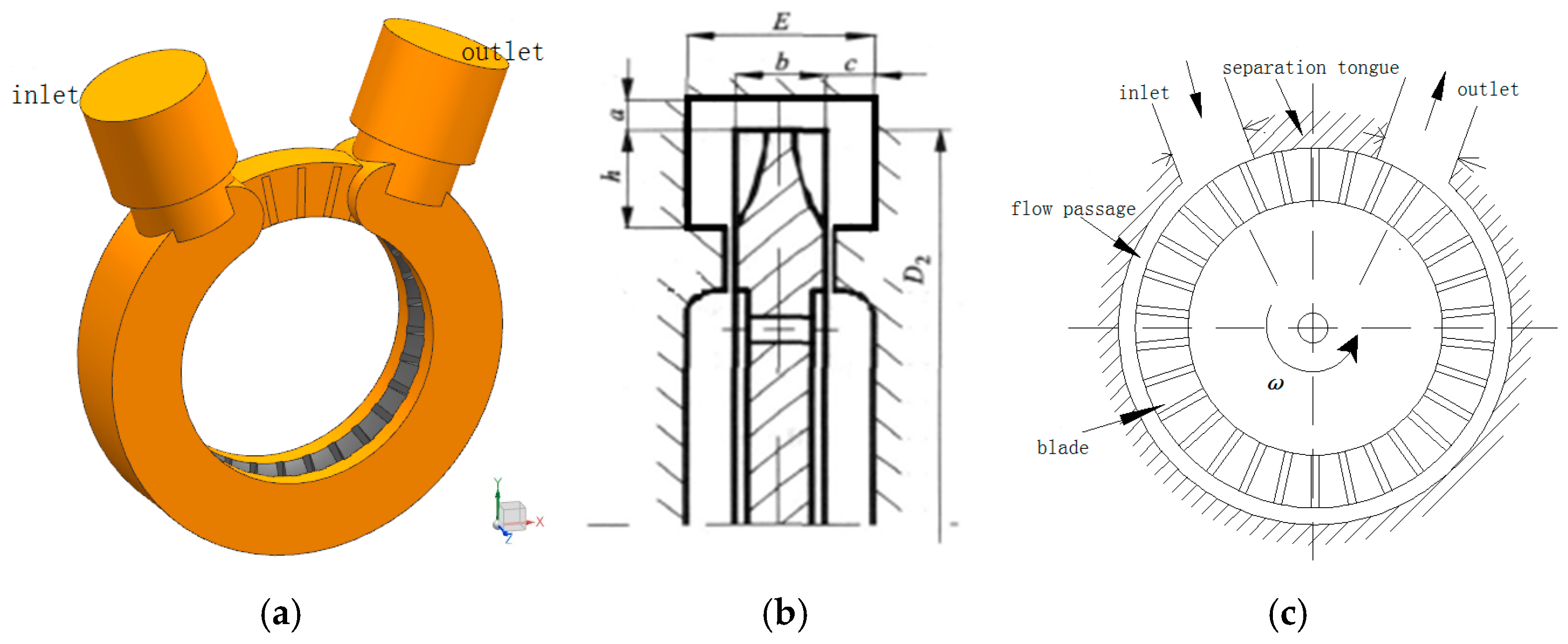
This study focuses on a typical double-support vortex pump with a closed impeller. The internal fluid domain of the vortex pump is illustrated in
Figure 1a [
30]. The hydraulic structural parameters and symbols at the axial section of the vortex pump are shown in
Figure 1b, while
Table 2 lists the symbols and physical descriptions of the pump’s structural parameters. The radial mid-plane of the vortex pump is depicted in
Figure 1c, which indicates the circumferential positions of the inlet and outlet, the blade distribution pattern of the closed impeller, and the location of the tongue. When fluid enters the flow passage of the vortex pump, the rotation of the impeller causes the radially uniformly distributed blades to periodically drive the fluid forward along the circumferential direction. During this circumferential movement, the rotational kinetic energy is gradually converted into fluid pressure energy, and the fluid is finally discharged through the pump outlet. The design parameters of the typical double-support vortex pump are summarized in
Table 2, which details the optimized structural parameters of the pump body based on vortex pump design theory.
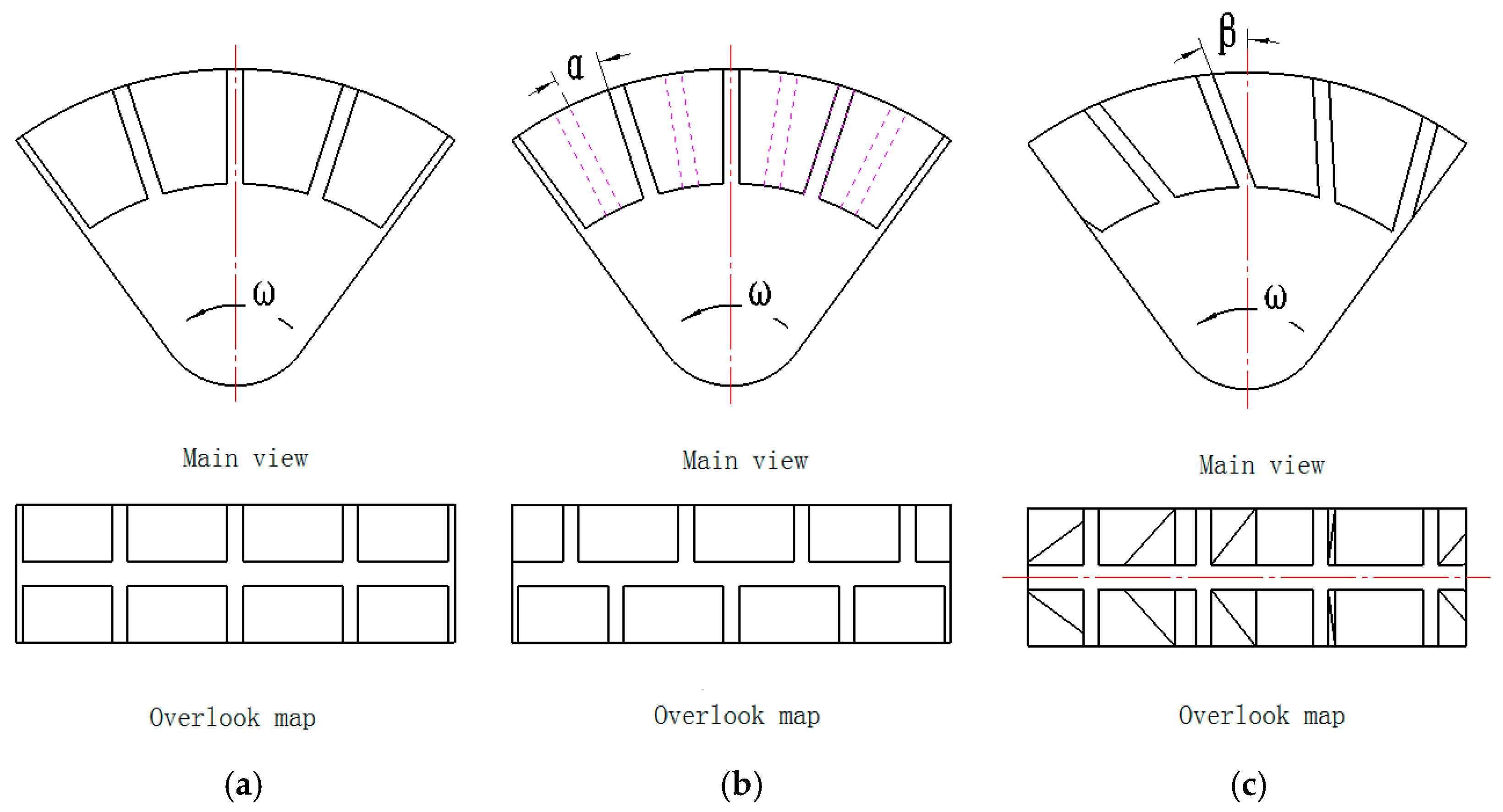
The vortex pump features a typical rectangular symmetrical flow passage cross-section and employs a classic closed impeller structure. The first blade distribution pattern studied in this paper is shown in
Figure 2a, which adopts a typical symmetrical blade arrangement radially distributed at the top of the closed impeller. The second blade distribution pattern investigated is illustrated in
Figure 2b, characterized by a staggered blade arrangement where blades are alternately distributed along the radial direction on both sides of the closed impeller top. The angle between the blades on both sides of the impeller along the radial direction is defined as α, in degrees (°). The angular parameters for the staggered blade distribution are listed in
Table 3, where α = 0° corresponds to the typical symmetrical blade distribution impeller structure inside a vortex pump, and the selected nonzero α values are representative small-to-large staggered offsets within the feasible geometric range of the present impeller configuration, especially for very large
α values approaching 90°; unfavorable geometric interference or excessive passage blockage may occur. The third blade distribution pattern examined is presented in
Figure 2c, utilizing an inclined deflection angle blade arrangement where blades are symmetrically distributed at the top of the closed impeller. The angle between the blade height and the impeller radius is defined as β, in degrees (°). The angular parameters for the inclined deflection angle blade distribution are provided in
Table 3, where β = 0° indicates the typical symmetrical blade distribution impeller structure inside a vortex pump. In
Figure 2, ω represents the rotational angular velocity of the impeller in rad/s. All three impeller types have 31 blades uniformly distributed around the outer circumference. The hydraulic parameters of the vortex pump flow passage, numerical simulation settings, and experimental operating conditions remain consistent across all cases.
3. Numerical Simulation Method
3.1. Numerical Computation Method
The flow in the vortex pump is assumed to be three-dimensional, incompressible, and turbulent. This is because the inlet pressure in the experimental test loop is maintained sufficiently high, and no cavitation noise or abnormal head drop was observed during the tests. Therefore, the single-phase incompressible flow model is adopted in this study. The governing equations are the steady Reynolds-Averaged Navier–Stokes equations, including the continuity equation and momentum equation, expressed as follows:
where
is the velocity vector,
is the static pressure,
is the fluid density,
is the dynamic viscosity, and
is the turbulent viscosity.
For the numerical simulation study on the flow characteristics of a double-support vortex pump under symmetric rectangular flow passage conditions, the numerical calculations employed the three-dimensional, steady-state Reynolds-Averaged Navier–Stokes (RANS) equations and the RNG k-ε two-equation turbulence model. The solution method utilized was the segregated implicit scheme. The coupling between pressure and velocity was achieved using the SIMPLEC algorithm. The pressure term was discretized using a second-order central difference scheme, while the velocity term, turbulent kinetic energy term, and turbulent dissipation rate term were discretized using a second-order upwind scheme. During the iterative calculations, the convergence criterion for all velocity components, k, and ε was set to 10
−5 [
17,
18].
3.2. Boundary Conditions
In the three-dimensional numerical simulation of a vortex pump conducted using the commercial software ANSYS FLUENT 14.0, the computational boundary conditions were set as follows:
(1) The inlet of the vortex pump was set as a mass-flow inlet condition, with a flow rate of 0.6 m
3/h specified according to the design parameters in
Table 2. All CFD cases in this study were conducted at the design flow rate
Qd = 0.6 m
3/h, which serves as the reference operating point for evaluating the relative effects of blade distribution.
(2) The working fluid was set as water with a defined density of 998 kg/m3.
(3) The outlet of the vortex pump was set as an outflow condition with a flow rate weighting of 1.
(4) The solid walls, including the flow passage walls and the tongue region, were set with the no-slip wall boundary condition. The standard wall function was applied in the near-wall region, and the relative angular velocity was set to ω = 0 rad/s.
(5) The three-dimensional simulation used a pressure-based solver. For the underdeveloped turbulent flow, the wall function method was employed for correction.
(6) The Multiple Reference Frame (MRF) model was employed to handle the water flow between the rotating impeller and the stationary pump volute. The impeller flow passage region was set in a rotating reference frame with a rotational angular velocity of ω = 345.4 rad/s assigned according to the design speed. The walls of the impeller were assigned a rotational angular velocity of ω = 0 rad/s.
3.3. Division of the Computational Grid
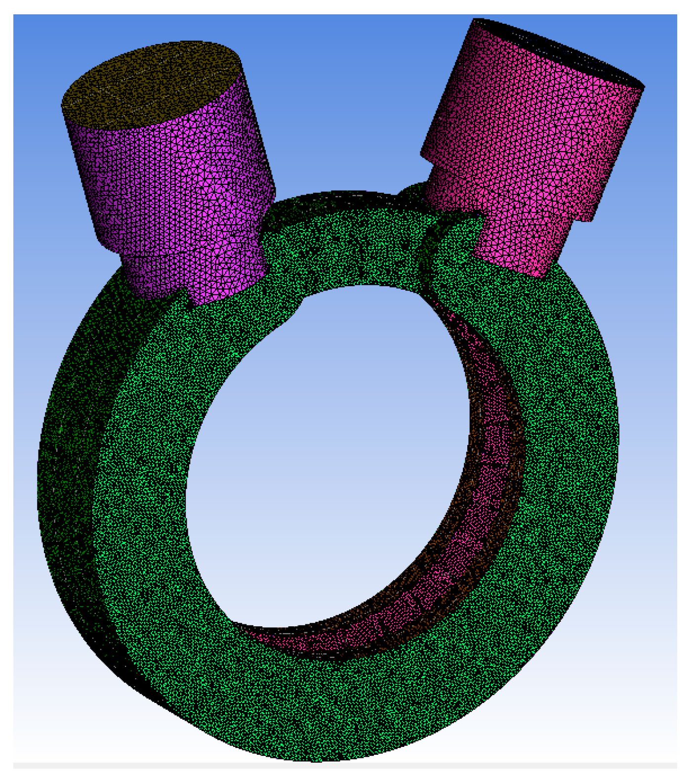
Due to the complex structural features within the flow passage of the vortex pump, such as variable cross-sections, narrow gaps, and varying dimensions, the computational domain was discretized using ICEM’s unstructured tetrahedral mesh, known for its strong adaptive capabilities. The grid distribution for the entire fluid domain and a cross-section of the flow passage is illustrated in
Figure 3. Local mesh refinement was applied to regions including the blade area, interfaces, and zones with significant geometrical changes, ensuring a smooth transition of element size from the wall boundaries towards the central region of the flow field. Additionally, the wall surfaces in the tongue region were assigned a finer mesh size to prevent large grid size increments in variable cross-sectional areas, which could compromise overall mesh quality and computational accuracy.
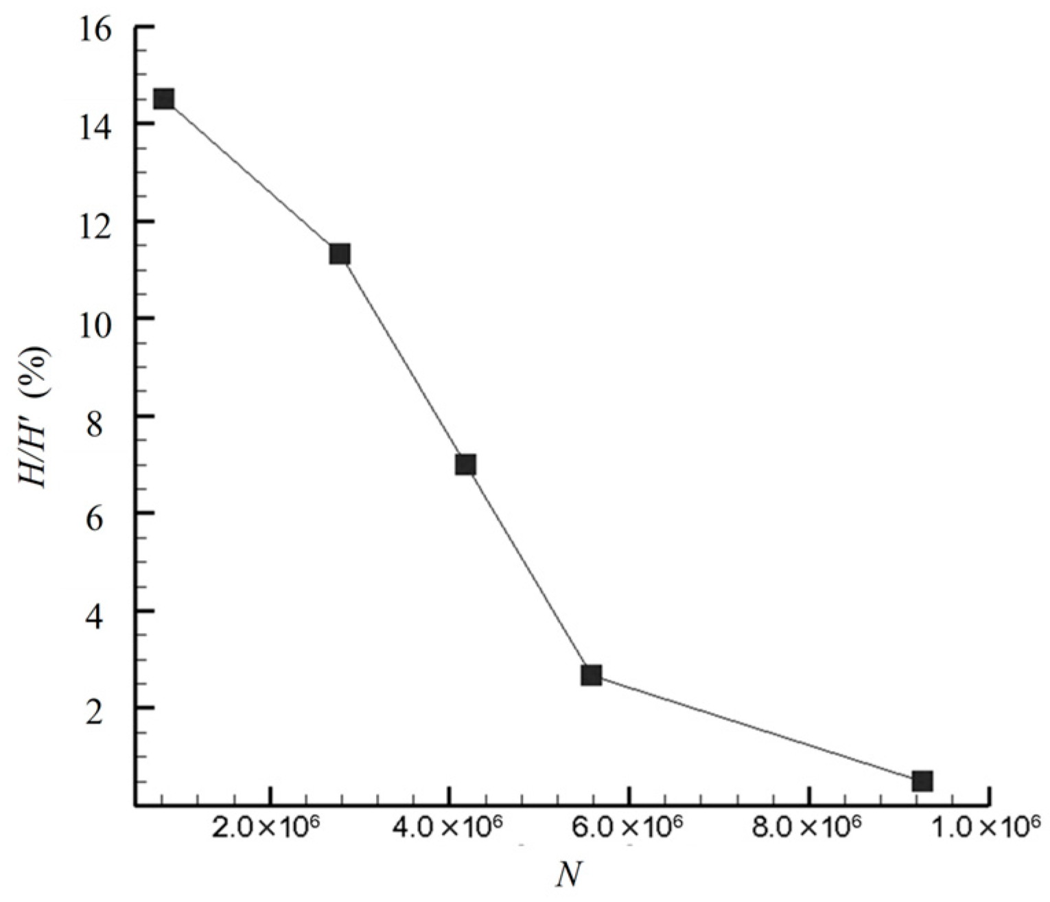
To enhance the reliability of the numerical simulation, a grid independence study was conducted using five different mesh counts. The comparative analysis of the vortex pump’s head percentage is presented in
Figure 4. Here, the vertical coordinate H/H’ (%) represents the ratio of the output head under different mesh counts, indicating the percentage deviation of results as the mesh number varies. The horizontal coordinate N represents the number of grid elements for each computational case. As the number of grid elements gradually increased, the percentage difference in the calculated head progressively decreased. Considering the balance between computational accuracy and efficiency, a final mesh count of approximately 5.58 × 10
6 was selected. The maximum deviation in the pump’s head across the different grids used in the independence verification was about 2.87%.
3.4. Key Performance Parameters
The expression for the head
of a vortex pump is as follows:
where
and
are the static pressures at the pump outlet and inlet, respectively, in Pa;
and
are the velocities at the outlet and inlet, respectively, in m/s.
and
denote the elevations at the outlet and inlet, and the elevation difference is negligible,
. Additionally, for water as the working medium,
= 998 kg/m
3 and
= 9.81 m/s
2.
The hydraulic power
of the vortex pump is defined as follows:
where
is the volumetric flow rate in m
3/h.
The required shaft power
is determined by the torque acting on the impeller:
where
is the torque in N·m,
is the angular velocity in rad/s, calculated based on the rotational speed
, and
represents the rotational speed of the impeller of the vortex pump, in r/min.
Therefore, the pump efficiency
can be expressed as the ratio between the hydraulic power and the shaft:
The total pressure is introduced to evaluate the energy conversion and loss characteristics of the flow field. The total pressure is defined as follows:
where
is the static pressure and
υ is the velocity magnitude. The variation in total pressure reflects the combined effect of pressure rise and hydraulic dissipation. A larger total pressure loss indicates stronger energy dissipation caused by viscous effects and vortex-related losses in the vortex pump.
3.5. Limitations of the Numerical Simulation
The present CFD model involves several assumptions and simplifications:
(1) A steady RANS approach is adopted; therefore, unsteady vortex evolution, vortex shedding and transient impeller–tongue interactions are not fully resolved.
(2) The turbulence closure provides time-averaged effects and may introduce model-form uncertainty for strongly vortical and separated flows.
(3) The working fluid is treated as incompressible, single-phase and isothermal with constant properties; cavitation, gas entrainment and temperature-dependent effects are not considered.
(4) Wall surfaces are assumed to be hydraulically smooth, and the geometry is idealized; manufacturing/assembly tolerances, surface roughness and possible leakage through small clearances are not explicitly modeled.
(5) Boundary conditions are simplified (uniform inlet/outlet specifications), and losses from the experimental loop components and installation effects are not included.
(6) The efficiency reported from CFD reflects hydraulic performance only; mechanical losses and measurement-related losses are not represented. These limitations may contribute to the systematic overprediction of head and efficiency compared with experimental measurements.
4. Vortex Pump Test System Method
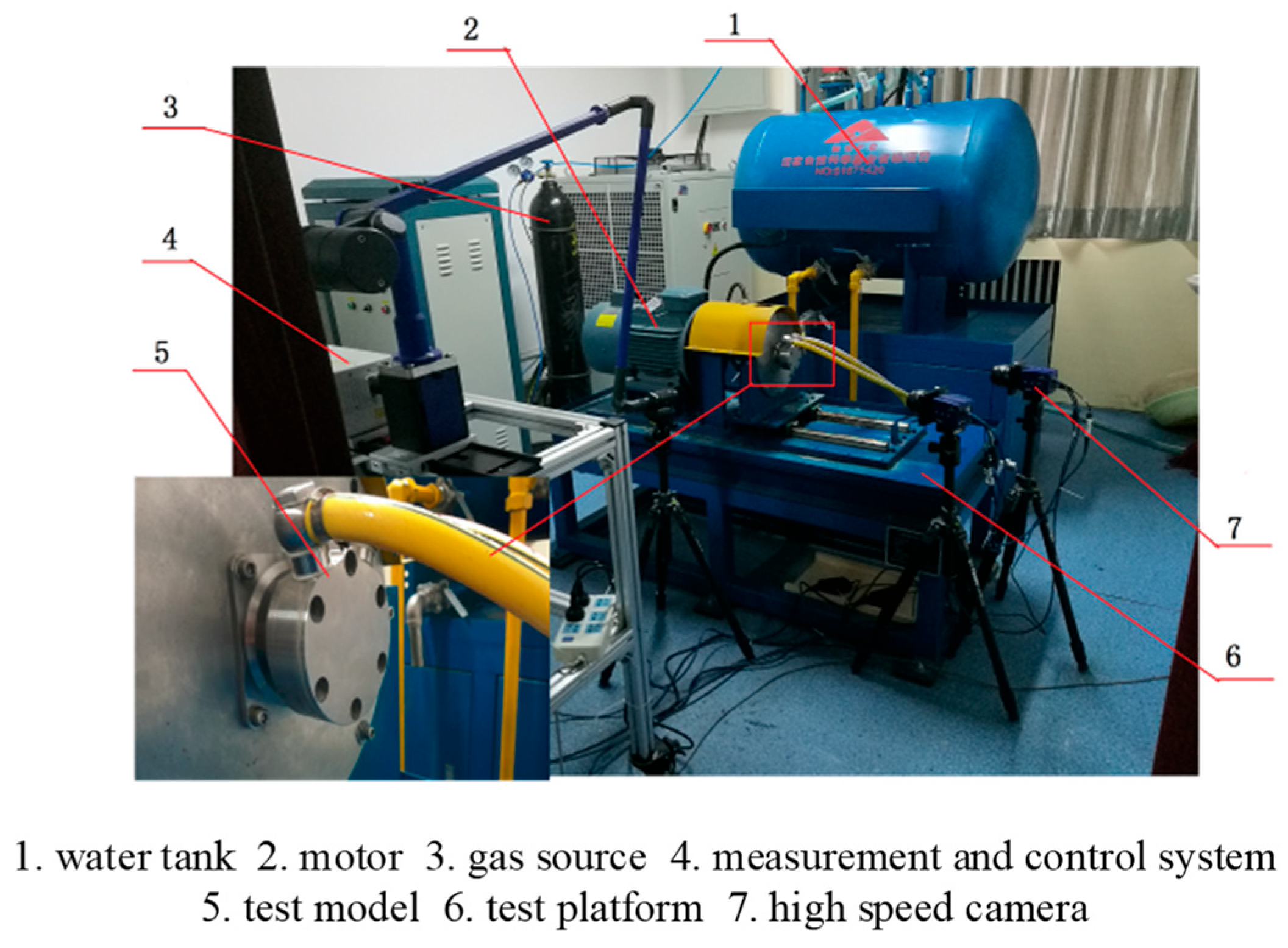
An experimental system for performance testing and flow mechanism research of an aviation vortex pump was designed according to the requirements of typical vortex pump testing standards. This system primarily includes a test bench, the test pump unit, electrical control, and a computer-based data acquisition system. The test bench controls the operating speed of the vortex pump through a variable-frequency drive motor. The vortex pump test supply system comprises flow meters, valves, pipelines, and a water tank. Electrical control is implemented via a Programmable Logic Controller (PLC), which handles the input and output control of the vortex pump and acquires test parameters through computer software. The real-time data collected by the software is subsequently analyzed and processed to obtain various test parameters and calculate the output performance of the vortex pump. A photograph of the vortex pump test bench and the installed test article is shown in
Figure 5.
The parameters of the experimental system are as follows: The vortex pump system utilizes three A-10 pressure transmitters from WIKA to collect inlet and outlet pressure parameters. The pressure transmitters have a range of 0 to 1 MPa and a measurement accuracy of ±0.5%. They were calibrated using a pneumatic calibrator prior to testing. The system is driven by a YVF 5.5 kW variable-frequency motor from ABB, with a frequency converter enabling an output control of 1.5 kW rated power; the motor power accuracy is class ±0.5%. The flow rate supplied to the vortex pump is measured by a KEWILL FE2-AL hydraulic flow meter, which has a range of 9 to 100 L/min and a measurement accuracy of ±0.5%. A water-based coolant serves as the supply medium, with its temperature generally maintained below 80 °C, and is circulated from a 400 L capacity tank. The water temperature is measured by a KEWILL TR30 temperature sensor with an accuracy of ±1 °C. Based on uncertainty analysis, the uncertainty in the output head of the vortex pump is calculated to be less than 7%.
During the experiments, the pump rotational speed was set by the variable-frequency drive, and the flow rate was adjusted using the regulating valve until the target operating point was reached. After the operating condition became stable, the inlet and outlet pressures were recorded by the calibrated pressure transmitters, and the flow rate and fluid temperature were measured simultaneously. The pump head was calculated using Equation (2). The pump efficiency was calculated using Equation (5), where the shaft power P was obtained from the motor power measurement, and the torque was calculated as M = P/ω; ω, determined from the measured rotational speed.
5. Numerical Simulation Research Results of the Vortex Pump
5.1. Influence of Inclined Blade Distribution in Closed Impellers on the Internal Flow Field of the Vortex Pump
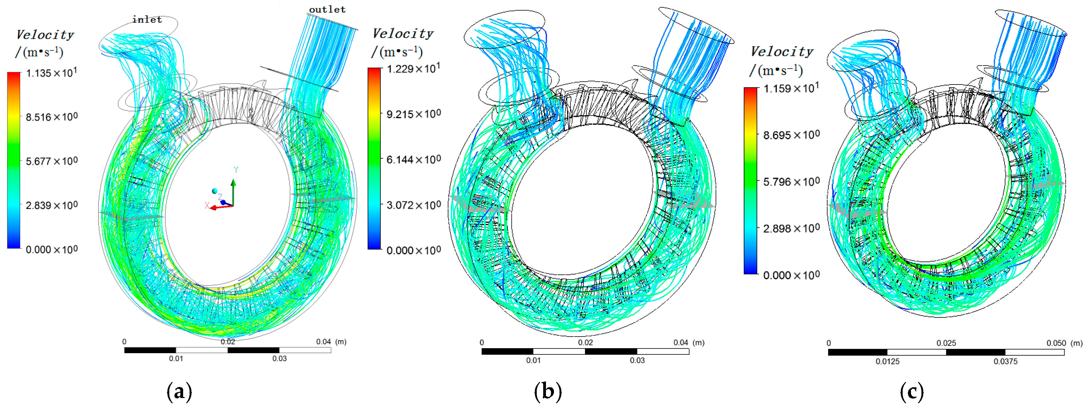
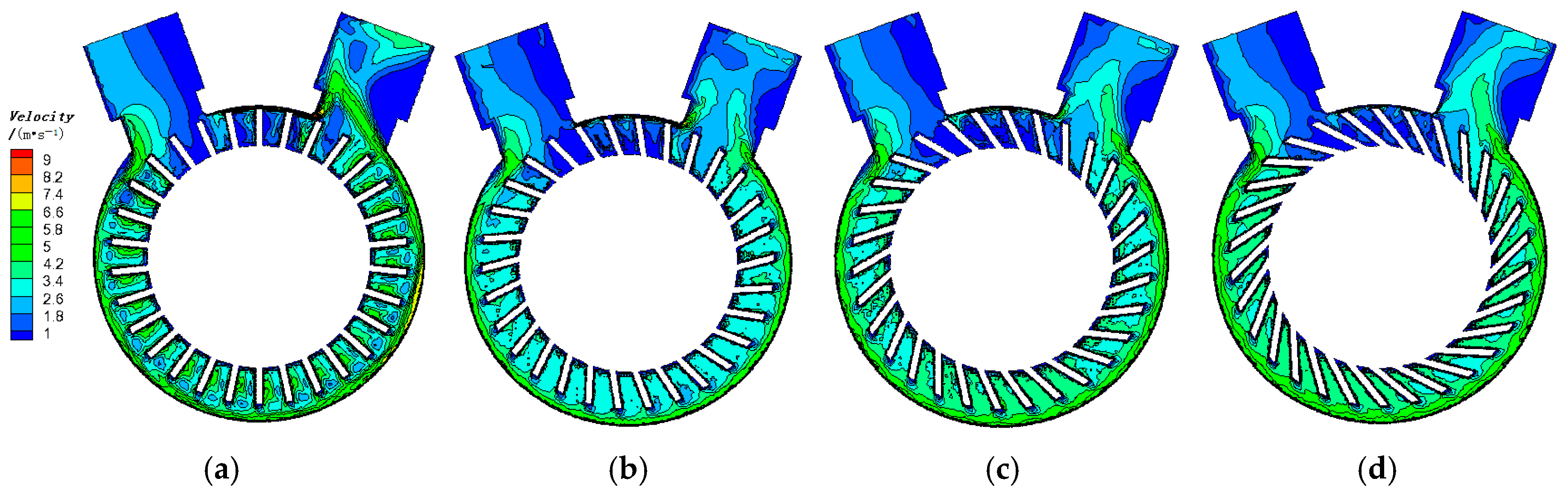
Figure 6 illustrates the internal velocity streamlines of the vortex pump with conventional blades and inclined blades, respectively. Under the condition of a symmetrical radial blade structure, when fluid enters the flow passage radially and exchanges energy with the radial blades, the rotating impeller acts on the fluid within the gaps of the closed blades, forming a longitudinal vortex in the radial cross-section of the flow passage. This longitudinal vortex evolves into a spiral-shaped continuous vortex structure that advances along the direction of blade rotation as the impeller rotates.
The formation of the longitudinal vortex in the radial section is attributed to the centrifugal force generated by the rotation, which pushes the fluid from the central region outward along the impeller’s radial direction toward the outer flow passage. After separating from the impeller, the fluid moves along the outer wall of the flow passage and returns to the smaller radius region at the base of the impeller. Due to the velocity difference between the radial blades and the circumferentially rotating fluid, when the fluid re-enters the base of the impeller blades, it lags into the adjacent blade gap, resulting in the formation of a continuous helical vortex structure propagating circumferentially.
A comparison of the velocity streamlines in
Figure 6a,b reveals that the inclined blade configuration introduces an incidence angle as the fluid enters the gaps of the closed impeller blades. This alters the timing and depth at which the fluid reaches the blade gaps, thereby modifying the vortex structure between the impeller and the fluid. An excessively large blade inclination angle hinders the fluid from reaching the blade root, reducing the duration and intensity of energy exchange and consequently impairing the pump’s head and efficiency. Conversely, when the blade inclination angle facilitates fluid access to the blade root, it optimizes the pump’s performance. Published studies indicate that blades inclined opposite to the direction of rotation promote constant angular momentum flow within the passage.
In contrast to inclined blades, radial blades have a weaker influence on the inlet region and the energy exchange between the impeller and the flow passage during rotation. They are less likely to impede energy transfer between the blades and the fluid in the inlet region and are not significantly affected by angle-induced changes in flow resistance or state. Apart from the flow loss due to directional change at the liquid inlet, the energy loss is primarily governed by the exchange between centrifugal force and the fluid’s centrifugal force within the flow passage. The deviation in the annular longitudinal vortex and shedding vortex structures along the flow direction further affects the output efficiency of the vortex pump.
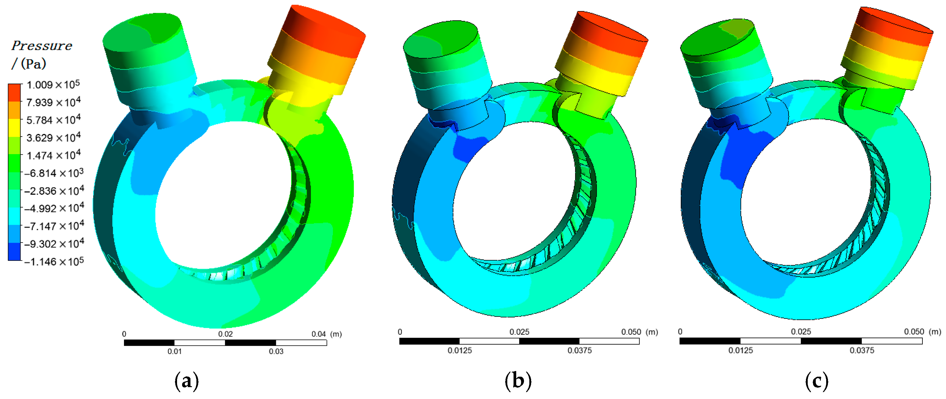
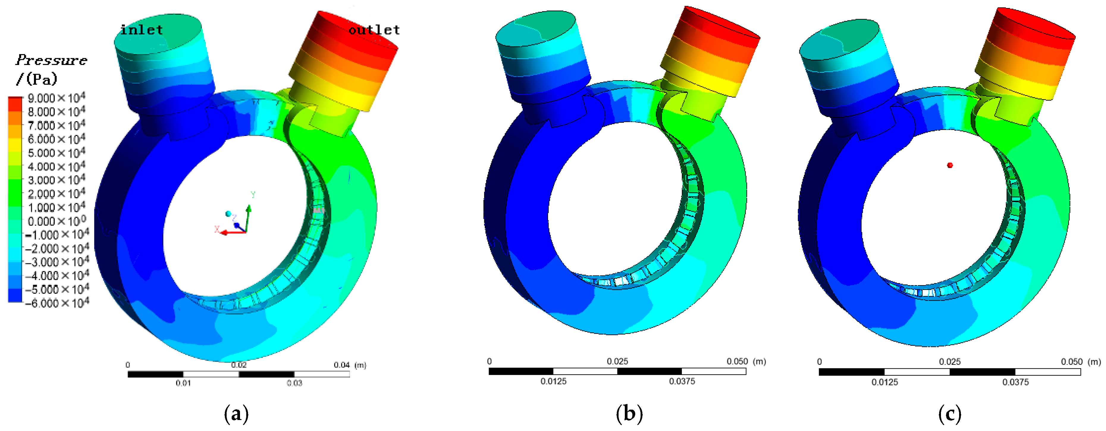
Figure 7 illustrates the wall pressure distribution of the vortex pump under three different blade inclination angles of the closed impeller. It can be observed that the pressure variation patterns along the flow path are generally similar for the symmetrical impeller configuration. The pressure difference between the inlet and outlet of the vortex pump initially increases and then gradually decreases as the blade inclination angle increases. This trend is attributed to the increased difficulty of fluid entering the blade passages when the inclination angle exceeds a certain threshold, which subsequently hinders the process of centrifugal force-driven fluid ejection along the radial direction. As a result, the energy exchange between the blades and the fluid becomes insufficient, leading to a gradual reduction in output pressure along the flow path. This inefficient energy transfer also results in low utilization of shaft power, ultimately affecting the head characteristics of the vortex pump.
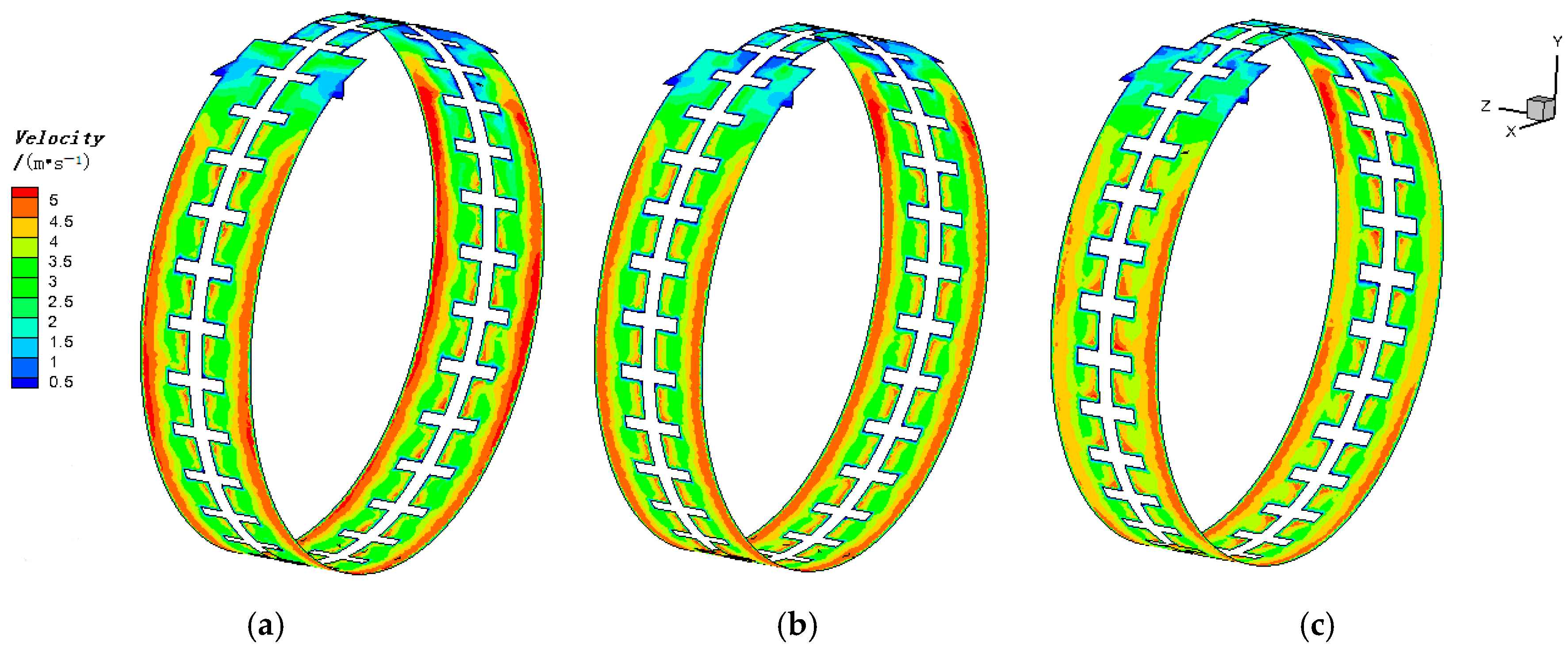
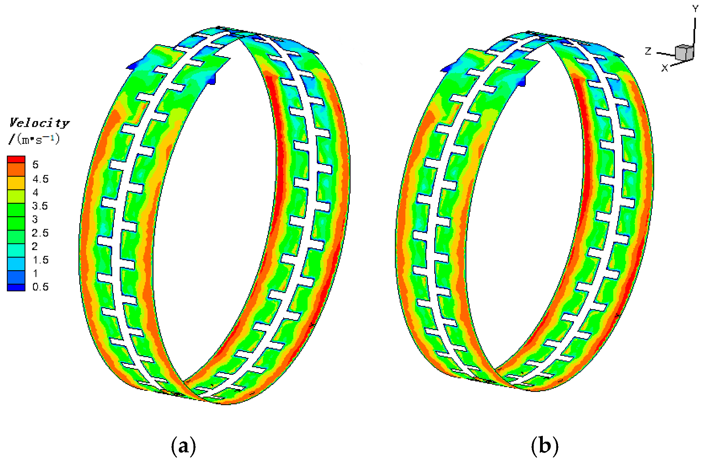
Figure 8 illustrates the velocity distribution on a cylindrical cross-section of the vortex pump under three different blade inclination angles of the closed impeller structure. As can be observed from the figure, as the blade inclination angle increases, the velocity gradient between the blades on the radial cross-section decreases. This reduction in the velocity gradient of the fluid between the blades affects the strength of the vortices formed within the gaps of the rotating blades and diminishes the energy transferred by the blades to the fluid in the flow passage, thereby adversely affecting the pump’s output power. Additionally, the shedding vortices between the blades gradually shift towards the downstream side of the adjacent blades along the flow direction. This phenomenon is analyzed to be due to the increase in the blade radial deflection angle, which causes the region of energy exchange between the fluid in the flow passage and the blades to shift towards the outer radius.
Figure 9 shows the velocity contour plot on a normal section. The attachment of the longitudinal vortices between the blades weakens as the blade deflection angle increases because a larger deflection angle changes the incidence of the incoming/returning flow and weakens its penetration into the blade-root region, thereby reducing the local relative-velocity level that sustains coherent vortical structures and shifting the vortex cores toward the downstream side of adjacent blades. As a result, the energy exchange between the impeller and the fluid becomes less effective, resulting in a decrease in the energy output efficiency of the impeller.
5.2. Influence of Staggered Blade Distribution in Closed Impellers on the Internal Flow Field of a Vortex Pump
Figure 6a,c illustrates the internal velocity streamlines of the vortex pump with conventional blades and staggered blades, respectively. The figures indicate that after the fluid enters the flow passage radially, it is directed into the impeller. The staggered blade arrangement generates asymmetric radial vortices within the flow passage, which propagate along the direction of blade rotation. Under the rotational acceleration of the asymmetric impeller, the fluid advances along the rotational direction, forming staggered longitudinal vortices in the radial direction. The periodic energy exchange between the fluid and the impeller results in a staggered helical flow pattern.
The staggered blade design enhances the energy exchange between the fluid and the impeller. This improvement is attributed to the asymmetric structure reducing the mutual interference that occurs during the helical progression of symmetrical longitudinal vortices, thereby facilitating the formation of alternating vortices with constant angular momentum flow within the passage. The centrifugal effect of the impeller promotes periodic energy exchange in the fluid, leading to the development of a complete annular longitudinal vortex structure and shedding vortices that propagate in a spirally alternating pattern along the flow passage. This process gradually increases the output power of the pump along the flow path.
Figure 10 illustrates the wall pressure distribution of the vortex pump under the operational conditions of a conventional impeller and two impellers with different staggered blade angles. Under identical flow passage structures, the staggered blade configuration exhibits a minor influence on the pressure distribution along the flow path because the overall pressure rise is mainly controlled by the main passage geometry and the centrifugal–recirculation balance, while changing the staggered angle mainly affects local flow details rather than the mean pressure build-up. The wall pressure distribution remains similar to the pressure field observed in the symmetrical radial blade impeller structure.
Figure 11 shows that variations in the two staggered blade angles have a limited impact on the velocity field distribution within the vortex pump cross-section because the mean velocity field is mainly governed by the global centrifugal–recirculation balance and the main passage geometry, while moderate changes in staggered angle mainly shift the phase of blade–flow interaction and redistribute the vortex cores locally rather than altering the overall momentum exchange level. Under the condition of an asymmetrically distributed closed impeller structure, the influence on the internal helical advancing vortex of the vortex pump is primarily manifested only at alternating circumferential positions, since the staggered blades introduce an alternating interaction between adjacent blade passages, leading to local patterns that repeat periodically along the circumference. Consequently, the impact on the output performance of the vortex pump is relatively small.
5.3. Influence of Blade Distribution in Closed Impellers on the Output Performance of Vortex Pumps
The experimental performance results are used as the baseline to validate the numerical simulation, and the comparison is summarized in
Table 3 and
Table 4.
Table 4 compares the experimental and numerical head and efficiency of the vortex pump equipped with a typical closed impeller at different rotational speeds. The two datasets exhibit consistent trends: when the rotational speed increases from 3000 to 3600 r/min, the experimental head rises by about 22.8% and the simulated head by about 22.2%; the experimental efficiency increases by about 22.2% and the simulated efficiency by about 20.8%. It is also noteworthy that the head changes by only about 0.26% between 3300 and 3600 r/min, showing an almost “saturated” behavior, whereas the efficiency still increases markedly by about 8.66%. This indicates that the benefit of higher rotational speed is mainly reflected in enhanced energy conversion and a reduced relative contribution of losses, rather than a proportional increase in head.
From a quantitative perspective, the numerical results are generally slightly higher than the experimental measurements: the head deviations are 6.99%, 6.80%, and 6.50% at 3000, 3300, and 3600 r/min, respectively, and the efficiency deviation ranges from about 7.89% to 9.40%. This stable systematic offset suggests that the numerical model slightly underestimates the total losses, which is consistent with the idealization of the experimental system in the CFD boundary conditions and wall treatment. More importantly, despite this offset, the numerical approach reproduces the trends and magnitudes of performance variation well, providing sufficient accuracy for the relative evaluation of blade-distribution schemes.
Table 5 further compares the influence of blade distribution on performance under the same operating condition. Cases 0–3 exhibit a clear and monotonic head–efficiency trade-off: the experimental head decreases by about 59.8%, while the experimental efficiency increases by about 38.1%. The numerical results show a highly consistent trend and magnitude, with a head reduction of about 60.5% and an efficiency increase of about 36.4%, indicating that the model captures the intrinsic sensitivity of performance to blade distribution. From a mechanistic viewpoint, the pronounced head reduction implies that these distribution changes weaken the pressure build-up capability and exacerbate hydraulic losses, whereas the efficiency improvement suggests that certain dissipation mechanisms are alleviated or that the operating point shifts toward a more favorable energy-conversion regime. In contrast, for Cases 4–5, the experimental head is only about 5.3% lower than that of Case 0, while the efficiency increases by about 18.8–19.5%. This indicates that the corresponding blade-distribution adjustment imposes only a minor penalty on head but yields a noticeable efficiency benefit. Overall,
Table 5 demonstrates that blade distribution can lead to a significant head–efficiency trade-off, and the final optimal scheme should be selected according to the design objective.
It should be noted that the above comparisons are conducted at the design operating point Qd. In practical applications, vortex pumps may operate over a wide flow-rate range. Under low-flow conditions around 0.5 Qd, the vortex pump is expected to exhibit intensified flow recirculation and stronger longitudinal vortex confinement, which may increase viscous dissipation and reduce efficiency, while maintaining relatively high head characteristics. In contrast, under high-flow conditions approaching 1.5 Qd, the momentum exchange process between the impeller and the side channel becomes less effective due to reduced residence time, leading to a gradual decline in head and possible efficiency degradation caused by enhanced flow separation and mixing losses. Although the present study focuses on the reference operating condition, these expected trends suggest that blade-distribution-induced performance characteristics persist over a wider operating range.
6. Conclusions
This study investigates the performance of a vortex pump influenced by the blade distribution of a closed impeller, focusing primarily on the effects of the blade including angle, tilt angle, and staggered blade arrangement. The following conclusions are drawn:
1. A three-dimensional numerical simulation method was employed to obtain the detailed internal flow field structure of the vortex pump with a closed impeller. The inclined blade structure of the closed impeller creates a certain incidence angle at the flow channel inlet. As this incidence angle increases, the output head of the vortex pump gradually decreases, while its efficiency gradually increases. However, the improvement in output efficiency resulting from the impeller blade tilt angle contributes insignificantly to the overall performance enhancement of the vortex pump.
2. Analysis of the flow field in the closed-impeller vortex pump reveals that the staggered blade angle facilitates the formation of asymmetric longitudinal vortices on both sides of the impeller. This arrangement causes the circumferentially propagating spiral vortices inside the two sides of the vortex pump impeller to advance alternately. While the direct impact of this phenomenon on the output head and efficiency is relatively minor, its potential significance for further optimization deserves attention.
3. Based on the experimental and numerical simulation results for the double-support vortex pump with a closed impeller, the trends observed for head and efficiency are generally consistent between the experimental data and the simulations. However, the numerical simulation results overestimate the head by approximately 7% and the efficiency by about 9% compared to the experimental measurements.
Optimizing the performance of vortex pumps can enhance their operational efficiency and equipment reliability, thereby extending the service life of the equipment and reducing operational costs. The optimized vortex pumps can be better applied in industries such as agriculture, chemical engineering, aviation, shipping, firefighting, and construction, meeting the industrial demand for low flow rate and high head.
This study focuses on the isolated effect of blade distribution under the present geometric constraints and at the reference operating condition, and the numerical predictions have been validated against the experimental performance tests. Several aspects were not considered and deserve further investigation, including a wider operating envelope with possible unsteady effects, the coupled influence of blade distribution with blade-profile parameters and multi-parameter optimization, leakage and clearance effects as well as manufacturing tolerances, and multi-phase phenomena such as cavitation or gas entrainment together with mechanical losses. From a practical engineering perspective, future performance optimization of vortex pumps should integrate blade-distribution-oriented vortex regulation with hydraulic loss reduction strategies and should be supported by CFD-based parametric screening combined with systematic experimental validation to provide more reliable and comprehensive design guidelines for vortex and side-channel pumps.




 ,
,