1. Introduction
The demand for freshwater in ocean-going vessels has increased continuously in recent years owing to the rapid growth of the global shipping industry. Freshwater is essential not only for the daily needs of crew members but is also an important working medium for ship cooling devices and process operations. Traditional port resupply consumes significant cargo space and deadweight capacity, thereby increasing transportation expenses. Although onboard seawater desalination devices (such as reverse osmosis and multi-effect distillation) can provide a certain level of self-sufficiency during voyages, the highly saline wastewater produced by these methods can adversely affect marine ecosystems [
1,
2]. Moreover, shipboard freshwater storage systems are susceptible to microbial contamination [
3,
4] and chemical pollution [
5], and mineral imbalance in desalinated water can pose health risks [
6,
7].
The International Maritime Organization (IMO) has set the goal of achieving net-zero greenhouse gas emissions from international shipping by 2050 [
8] and has established mandatory technical and operational measures, such as the Energy Efficiency Design Index (EEDI), Energy Efficiency Existing Ship Index (EEXI), and Carbon Intensity Indicator (CII) [
9]. Consequently, the development of low-energy, renewable freshwater production technologies for ships has become an inevitable trend in the green development of shipping.
Ship waste heat recovery technology offers new approaches for improving energy utilization efficiency. Waste heat from main engines accounts for approximately half of the total fuel energy, with approximately a quarter of it being lost through exhaust gases at temperatures of 250–500 °C [
10]. The effective recovery and utilization of this medium-to-low-grade exhaust is considered an important target for enhancing the overall energy efficiency of marine vessels. Among waste heat recovery technologies, the utilization of an Organic Rankine Cycle (ORC) system to comprehensively recover waste heat can boost the main engine efficiency by 13.5–21% [
11,
12]. Waste-heat-driven rotary desiccant systems have also demonstrated favorable thermal performance [
13].
Rotary desiccant technology achieves continuous air dehumidification through a cyclical adsorption–desorption process using desiccants. Recently, significant progress has been made in the development of high-performance composite desiccants, including silica gel combined with lithium chloride, silica gel–calcium chloride composites [
14,
15], and metal–organic frameworks (MOFs) [
16,
17]. At the system optimization level, the research team led by Chen Wu has improved energy-saving effects by optimizing rotary speed [
18,
19] and fresh air parameters [
20] for marine rotary desiccant air conditioning systems and has validated the superior performance of two-stage marine rotary desiccant air conditioning systems [
21].
In the field of freshwater production using rotary desiccant dehumidification, Kushwaha et al. [
22,
23,
24] developed solar-driven rotary desiccant-based atmospheric water generation (AWG) systems primarily for use in arid land regions. However, research specifically targeting high-humidity marine environments on ships remains limited. Although there have been innovations in shipboard seawater desalination technologies, such as novel reverse osmosis processes and membrane distillation, integrated “waste heat–dehumidification–condensation” solutions specifically designed for the high-humidity marine environment of ships have received relatively limited attention, and a systematic performance evaluation and working condition adaptability analysis are urgently required.
Based on the above considerations, this study focuses on a 20,000 twenty-foot equivalent unit (TEU) class container ship and proposes a technical solution for an integrated shipboard waste-heat-driven freshwater production and fresh air preconditioning system based on an existing two-stage rotary desiccant fresh air preconditioning system. This study included system design, theoretical modeling, performance testing, and adaptability analysis under various working conditions, with a comparative analysis of freshwater production rates and dynamic characteristics under varying seawater temperatures, outlet temperature differences, and system configurations.
2. Materials and Methods
2.1. System Design
2.1.1. System Architecture
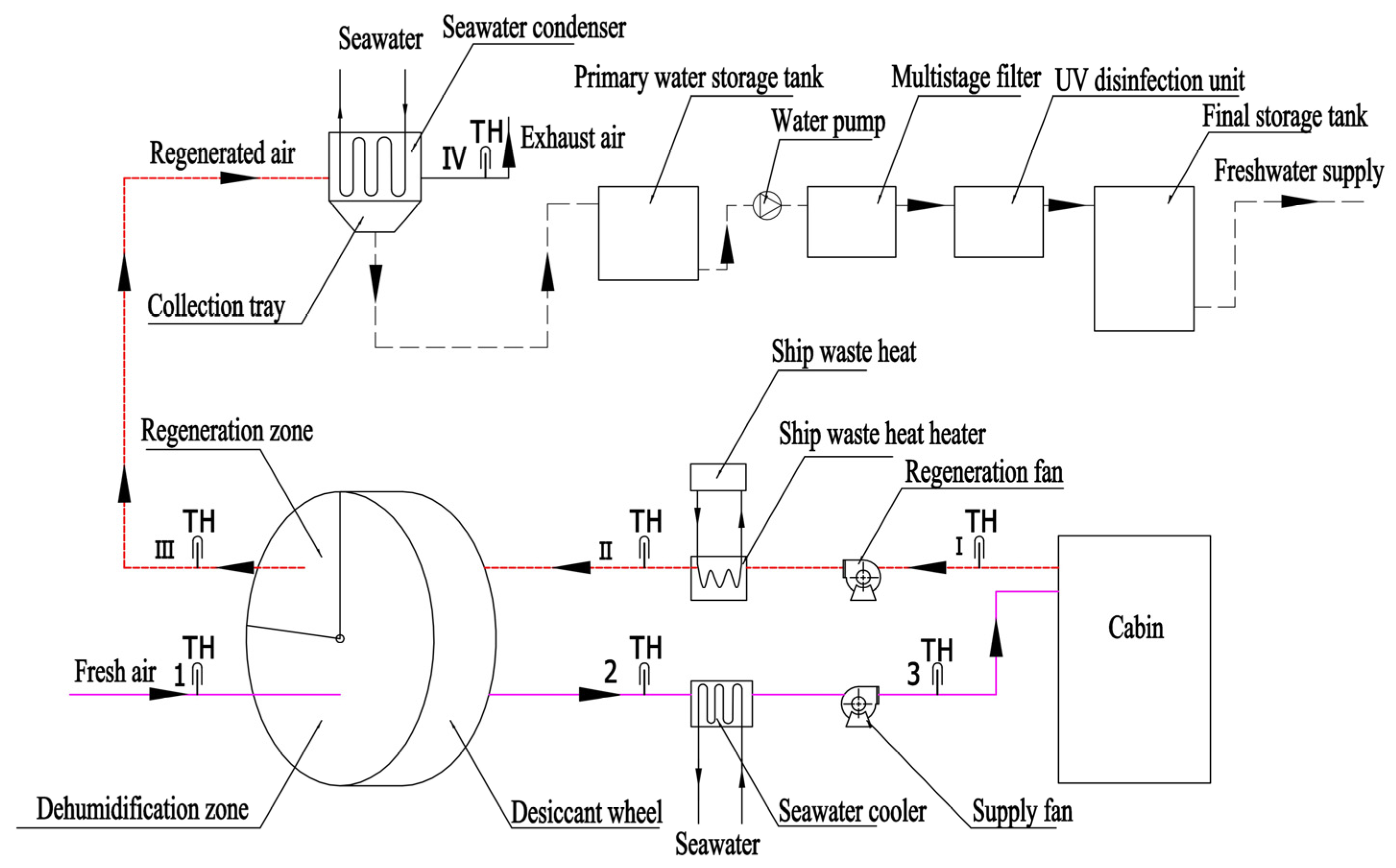
The integrated system for producing freshwater and pretreating fresh air using ship waste heat, developed in this study, mainly consists of a dehumidification wheel, a heater that utilizes ship waste heat, a seawater cooler, a seawater condenser, and water purification and sterilization devices. It is divided into two main functional modules: a dehumidification air conditioning subsystem and a freshwater production subsystem. The system flow is illustrated in
Figure 1. The system utilizes waste heat from the ship exhaust as the regeneration heat source for the desiccant wheel and seawater as the cooling source for the air. By organically combining the processes of dehumidification and freshwater production, the system achieves cascade energy utilization and functional synergy.
2.1.2. Dehumidification Air Conditioning Subsystem
The desiccant wheel in the dehumidification air-conditioning subsystem is the core component of the system. It is divided into two fan-shaped sections, the dehumidification and regeneration zones, in a 3:1 ratio (with central angles of 270° and 90°, respectively). Effective thermal insulation was achieved using PTFE silicone strips, and the wheel was driven by a variable-frequency motor. When humid, fresh ocean air enters the dehumidification zone, the desiccant quickly absorbs the water vapor in the air, thereby reducing the humidity. Because the dehumidification process is an isenthalpic dehumidification process, the air temperature increases owing to the release of adsorption heat after dehumidification. The air is then cooled using a seawater cooler and supplied as pretreated fresh air to the air-conditioning system. When the desiccant in the dehumidification zone approaches saturation after absorbing moisture, it rotates into the regeneration zone. After being heated by the waste heat heater, the cabin return air is blown through the desiccant in the regeneration zone, which causes the absorbed water to be desorbed and released at a high temperature, thereby restoring the moisture-absorption capacity. The released moisture is carried away as water vapor into the regeneration air, forming high-temperature and high-humidity air.
2.1.3. Freshwater Generation Subsystem
The freshwater generation subsystem includes a seawater condenser, air ducts, a water collection device, and a water purification unit. The high-temperature, high-humidity air released by the desiccant regeneration process is directed into the seawater condenser. Using indirect heat exchange with seawater, the water vapor in the regeneration air is cooled below its dew point, causing condensation into liquid water. The condensate flows by gravity into a collection tray, then enters the primary water storage tank, and is purified through multistage filtration and UV disinfection to ensure that the freshwater meets domestic water standards (salinity < 1000 ppm, pH 6.50–8.5, residual chlorine 0.05–0.5 mg/L, etc.) [
25]. If required, a remineralization unit can be integrated downstream of the purification system to address potential mineral imbalances and meet long-term crew health requirements. The purified freshwater is stored in a final storage tank equipped with a real-time monitoring system for water quality.
2.1.4. Key Parameter Configuration
Based on our previous research [
18,
19,
20], theoretical analysis, and experimental verification, the key parameters were designed as follows:
1. Wheel speed: 10 r·h−1 (revolutions per hour) (baseline), adjustable range 6–15 r·h−1. At this speed, the adsorption-regeneration cycle was well matched, and the dehumidification efficiency was optimal.
2. Regeneration temperature: 120 °C (design value), adjustable range: 80–140 °C. At this temperature, the silica gel desiccant regeneration efficiency is high while avoiding performance degradation due to excessive temperatures. This design value is consistent with previous experimental optimization studies on marine silica-gel-based rotary desiccant systems [
19,
20,
21].
3. Fresh air flow rate: 10,000 m3/h (dehumidification zone); regeneration air flow: 3300 m3/h (regeneration zone). This ratio ensured adsorption–desorption equilibrium.
4. Seawater flow rate: calculated according to the condensation load, approximately 1.5–2.0 kg/s under optimal conditions.
2.2. Establishment of Theoretical Model
2.2.1. Model of the Dehumidification Process
The dehumidification process in the wheel is described by mass and energy conservation equations as follows: For the dehumidification zone, the change in the moisture content of the air as it passes through the wheel is expressed as
Moisture absorption:
where
and
represent the inlet and outlet air humidity ratios of the rotary wheel (kg/kg dry air), respectively;
denotes the mass flow rate of dry air in the dehumidification zone (kg/s).
Because the adsorption process releases adsorption heat, the temperature rise in the air after dehumidification is expressed as
where
represents the latent heat of vaporization of water (2500 kJ/kg), and
is the specific heat capacity of air at constant pressure (1.005 kJ/(kg·K)).
2.2.2. Model of the Regeneration Process
In the regeneration zone, heated air is used to purge the saturated desiccant, causing it to desorb moisture. The changes in moisture content and the amount of desorbed water during the regeneration process were as follows:
where
and
represent the moisture content at the regeneration air inlet and outlet, respectively (kg/kg dry air), and
denotes the mass flow rate of dry air in the regeneration zone (kg/s).
Under steady-state operation, the amount of moisture absorbed and desorbed should remain balanced.
2.2.3. Model of the Condensation Process
After regeneration, high-humidity air enters the seawater condenser. When the air temperature drops below the dew point, the water vapor begins to condense. According to the heat and mass transfer theory [
26], the yield of condensed water is expressed as follows:
In the formula, represents the saturated humidity ratio (kg/kg dry air) corresponding to the air temperature at the condenser outlet.
The heat balance equation in the condenser is as follows:
where
is the outlet temperature of the regeneration air (°C),
is the outlet air temperature of the condenser (°C),
is the mass flow rate of seawater (kg/s),
is the specific heat capacity of seawater (3.9 kJ/(kg·K)), and
and
are the inlet and outlet temperatures of seawater (°C), respectively.
According to the thermodynamic relationship of moist air, the dew point temperature can be calculated using the Magnus-Tetens approximation method [
27]:
Among them:
where
represents air temperature (°C), and
represents relative humidity, and the constants are
.
2.3. Performance Evaluation Indicators
To comprehensively assess the performance of the system, the following indicators were established:
2.3.1. Indicators of Freshwater Production
1. Daily freshwater production:
where
is measured in kg/h, and the density of water is 1000 kg/m
3.
2. Actual vessel demand satisfaction rate:
where
represents the actual daily average freshwater demand of the vessel (7–12 m
3).
2.3.2. Energy Efficiency Index
1. The energy consumption of the auxiliary machines was measured per unit of produced water.
In this context, refers to the power of the fan (measured in kW), and refers to the power of the seawater pump (also measured in kW).
According to [
28], the fan power can be estimated as
where
is the air volume (m
3/s), and
is the system pressure drop (Pa). According to Chapter 24 of the ASHRAE Handbook (2024) [
28], the air-side pressure drop of the rotary dehumidifier under standard conditions is approximately 157–214 Pa. Considering the additional resistance from the filters and system piping, the system design usually uses a total pressure drop of
= 200–400 Pa as the calculation basis;
is the fan efficiency, which is typically taken as 0.75 based on engineering practice.
According to reference [
28], fan power can be estimated using the following formula:
where
is the acceleration due to gravity (9.8 m/s
2),
is the head (m), with the head for a ship’s condenser typically about 10–15 m [
12],
is the seawater density (approximately 1025 kg/m
3), and
is the pump efficiency, which is taken as 0.70 based on engineering practices.
Preliminary estimates under optimal conditions ( = 60.26 kg/h = 0.06026 m3/h), the fan power is approximately 0.03–0.05 kW, seawater pump power is approximately 0.02–0.03 kW, and total auxiliary machine power is approximately 0.05–0.08 kW. The auxiliary power consumption per unit of produced water is approximately 0.83–1.33 kWh/m3, with <1.5 kWh/m3 used as an evaluation benchmark.
2. Seawater temperature sensitivity coefficient:
This coefficient reflects the extent to which changes in seawater temperature affect freshwater production.
3. Outlet temperature difference sensitivity coefficient:
represents the standard freshwater production rate, and indicates the change in the freshwater production rate under different conditions compared to the reference rate. refers to the outlet temperature difference, that is, the extent to which the temperature increases as seawater enters and exits the condenser. represents the change in the current temperature difference compared to the reference outlet temperature difference, specifically, how much larger or smaller it is than the original reference outlet temperature difference.
4. Freshwater production stability under various operating conditions
where
and
represent the maximum and minimum freshwater productions under all operating conditions, respectively.
2.4. Operating Parameters and Performance Testing
It should be clarified at the outset that the validation conducted in this study is based on experimentally measured air state parameters obtained from a previously established and validated rotary desiccant air pretreatment platform. The condensation and freshwater production results reported in this study are theoretical calculations derived from the thermodynamic model using these experimental air-state inputs. To date, a fully integrated prototype for direct experimental measurements of freshwater production has not been constructed.
To evaluate the accuracy of the theoretical model, this study proposes the addition of a freshwater production subsystem based on the group’s two-stage rotary desiccant air pretreatment experimental platform from previous research. Experimental conditions: the desiccant wheel used silica gel as the drying agent, with an outdoor fresh air temperature of 36.1 °C and relative humidity of 61.5%. The wheel rotation speed was 10 r·h−1. Regeneration air was drawn from the cabin return air at a regeneration temperature of 120 °C. Based on the experimental tests, the air temperature at the outlet of the first-stage regeneration zone was 59.7 °C, with a relative humidity of 32.0%, and the dry air density was approximately 0.9947 kg/m3.
Considering a 20,000 TEU container ship as an example, the total air supply for the air conditioning system is approximately 20,000 m
3/h. According to the applicable regulations for ship air conditioning, the fresh air supply for ocean-going ships must be no less than 50% of the total air supply [
29]. Therefore, the fresh air volume was set at 50% of the total air supply, amounting to 10,000 m
3/h, which served as the processing air volume in the rotary desiccant area of the system. The regeneration air volume was one-third of the air volume in the dehumidification area, that is, 3300 m
3/h.
According to the enthalpy-humidity chart, at a temperature of 59.7 °C and relative humidity of 32.0%, the air moisture content was approximately 34.35 g/kg dry air, and the dew point temperature was 37.06 °C. Using the South China Sea region as an example, a seawater temperature of 25–29 °C was selected [
30]. In this study, the temperature difference at the condenser outlet was defined as the difference between the cooled air outlet temperature and the seawater inlet temperature, with a set outlet temperature difference of 2–6 °C, to calculate the condensate production under various operating conditions. The above data were used for subsequent calculations of freshwater production and model validation.
3. Results
Unless otherwise stated, all freshwater production results presented in this section are theoretical condensate yields calculated based on experimentally measured air state parameters and the established thermodynamic model.
3.1. Effect of Seawater Temperature and Outlet Temperature Difference on Freshwater Production
3.1.1. Variation Pattern of Freshwater Production
Table 1 shows the theoretically calculated condensate freshwater production based on the experimentally measured air-state parameters at different seawater temperatures and outlet temperature differences. According to the data, both the seawater and outlet temperature differences noticeably affected freshwater production, exhibiting distinct and regular variations.
3.1.2. Effect of Outlet Temperature Difference
Under constant seawater temperature, the greater the outlet temperature difference, the lower the condensate yield. When the seawater temperature is 25 °C, as the outlet temperature difference increases from 2 °C to 6 °C, the amount of condensate decreases from 60.26 kg/h to 40.09 kg/h, a reduction of 33.5%.
According to Equation (17), the outlet temperature difference sensitivity coefficient = −0.167, indicating that a 1 °C increase in the outlet temperature difference results in an approximately 8.4% decrease in freshwater production under reference conditions. From a thermodynamic perspective, the outlet temperature difference directly affects the condenser outlet air temperature, which determines the corresponding saturation humidity ratio. However, its influence is indirect, as it mainly modifies the terminal temperature of the cooling process. Therefore, although reducing the outlet temperature difference enhances condensation, its overall sensitivity remains moderate.
From the perspective of heat and mass transfer, reducing the outlet temperature difference has the potential to improve the heat exchange efficiency of the condenser, allowing more water vapor to condense and precipitate. However, if the outlet temperature difference is too small, it will increase the seawater circulation volume and pump power consumption; therefore, a balance must be achieved between freshwater production and energy consumption. It is recommended that, in practical applications, the outlet temperature difference be controlled within 2–3 °C to achieve higher freshwater production and reasonable energy consumption.
3.1.3. Effect of Seawater Temperature
When the outlet temperature difference is fixed, the higher the seawater temperature, the lower the yield of the condensate water. For example, when the outlet temperature difference is 2 °C, as the seawater temperature rises from 25 °C to 29 °C, the condensate water yield decreases from 60.26 kg/h to 40.09 kg/h, a drop of 33.4%.
According to Equation (16), the sensitivity coefficient of seawater temperature is = −0.334. This indicates that a 1 °C increase in seawater temperature leads to an approximately 1.34% reduction in freshwater production under the reference condition.
The system shows a higher sensitivity to seawater temperature because it directly determines the coolant temperature level, which governs the thermodynamic driving force for condensation. Specifically, freshwater production is controlled by the temperature difference between the air dew point and seawater temperature. An increase in seawater temperature reduces this driving force, leading to a more pronounced decrease in condensation capacity compared to changes in outlet temperature difference.
3.1.4. Analysis of Extreme Conditions
The maximum freshwater production occurred under the low temperature and low temperature difference combination (seawater at 25 °C, outlet temperature difference of 2 °C), reaching 60.26 kg/h, whereas the minimum freshwater production occurred under the high temperature and high temperature difference combination (seawater at 29 °C, outlet temperature difference of 6 °C), reaching 14.91 kg/h. The difference between the two was approximately fourfold (multi-condition stability = 4.04), indicating that environmental conditions exert a pronounced influence on system performance and that the system must be adaptable to various operating conditions.
3.2. Evaluation of Vessel-Requirement Matching Degree
3.2.1. Performance Evaluation of Single-Stage System
Taking a 20,000 TEU large container ship as an example, its average daily freshwater demand is approximately 7 to 12 m
3 [
31], including 2 to 4 m
3 for crew living and cooking, 4 to 6 m
3 for engine room equipment cooling and rinsing, and 1 to 2 m
3 for emergency reserves. The performance evaluation of the single-stage system under different operating conditions is presented in
Table 2.
As shown in
Table 2, under optimal conditions (seawater temperature 25 °C, outlet temperature difference 2 °C), the system produced 1.45 m
3 of condensate water per day, accounting for 20.7% of the minimum requirement (7 m
3). Although the single-stage system cannot fully meet the freshwater demand of the ship, this portion of waste-heat-driven freshwater with low auxiliary electrical energy input can operate in conjunction with the existing seawater desalination system, thereby reducing the operational load of the reverse osmosis unit by approximately 20–25%. Simultaneously, it provides pretreatment for fresh air, contributing to a reduction in the energy consumption of air-conditioning systems [
32]. Therefore, this system demonstrates the potential for engineering applications and can serve as an auxiliary freshwater production solution.
3.2.2. Comparative Analysis of Energy Efficiency
Table 3 lists the performance indicators of various shipboard freshwater production technologies, highlighting the advantages of this system in terms of energy efficiency.
To enable a clearer comparison with other waste-heat-driven desalination concepts, two normalized performance indicators are emphasized in this study:
(1) specific auxiliary electrical energy consumption (kWh·m−3), which only accounts for the electricity consumption of fans and seawater pumps, and
(2) freshwater yield per unit processed air flow (m3 water per m3 air).
It should be noted that the proposed system is not intended to replace conventional desalination systems, but rather to serve as an auxiliary freshwater production solution driven primarily by ship waste heat. Compared with waste-heat-assisted MED and RO systems reported in the literature, the proposed system exhibits a lower specific electrical energy consumption, while providing a modest but meaningful freshwater yield under continuous operation, making it particularly suitable for integration with marine HVAC systems.
As shown in
Table 3, the unit power consumption for freshwater production in this system is less than 1.5 kWh/m
3, which is only 25% to 50% of reverse osmosis systems (3–6 kWh/m
3) and is at or below the same level as multi-effect distillation (1.5–4 kWh/m
3). Even when considering secondary and tertiary system configurations, the power consumption is less than 2.5 kWh/m
3, allowing for the comprehensive utilization of ships’ waste heat resources and meeting the IMO efficiency requirements and dual-carbon strategic goals.
3.3. Analysis of System Configuration Optimization
Based on the theoretical analysis in
Table 3, the secondary system offers the best balance of performance and cost, whereas the tertiary system can achieve a higher compliance rate but comes with a notably increased complexity and investment.
1. Secondary System Design
First Stage: A flow rate of 10,000 m3/h of fresh air is processed, and the regeneration zone produces high-humidity air (moisture content of 34.35 g/kg).
Second stage: The regenerated air from the first stage is used as the input air for further dehumidification and concentration, increasing the moisture content to 55–60 g/kg.
Condenser: Processes the regenerated air from the second stage, with a theoretical freshwater production of 2.9–4.3 m3/day.
Spatial Arrangement: Two desiccant wheels in series sharing one condenser and purification system increased the footprint by approximately 40–50%.
Water Yield Improvement Process: The first step is to remove moisture from the air. This lowers the moisture content of the fresh air and moves the water from it to the regenerated air. In the second stage, the high-humidity air is further dehumidified, effectively acting as a secondary concentration of water vapor. According to the conservation of mass:
Here, = 55–60 g/kg (moisture content at the outlet of the second stage), which is a 60–75% increase compared to 34.35 g/kg in the single-stage system.
Under optimal operating conditions (seawater at 25 °C and outlet temperature difference of 2 °C), the condensed water yield is
The daily water output is approximately 2.9–3.2 m3, meeting 41–46% of the demand. With condenser optimization (reducing the outlet temperature difference to 1.5 °C), the satisfaction rate reached 50–55%. It should be noted that achieving such a low outlet temperature difference may require larger heat exchanger surfaces and increased seawater flow rates, potentially increasing capital costs and pumping power, which should be carefully balanced in practical designs.
2. Single-Stage + Reverse Osmosis Integrated Solution
For most vessels, it is recommended to use the “single-stage main system + small-scale reverse osmosis” integrated solution: this system handles 20–25% of the freshwater production task (1.4–1.8 m3/day); the reverse osmosis unit handles 75–80% of the freshwater production task (5.2–6.0 m3/day); the scale of the reverse osmosis unit is reduced by 20–25%, which lowers investment costs and extends the membrane lifespan. In the event of a malfunction in this system, the reverse osmosis unit can operate at full capacity to ensure the safety of the freshwater supply. This solution comprehensively considers technological maturity, cost-effectiveness, and reliability, making it the optimal engineering solution.
3.4. Analysis of Route Adaptability
Seawater temperature varies significantly across different latitudes, leading to corresponding changes in system performance.
Table 4 presents an analysis of the system’s adaptability for typical routes.
1. High-latitude routes exhibited the best adaptability.
On high-latitude routes, such as the North Pacific and North Atlantic, seawater temperatures remain between 10 °C and 20 °C year-round, allowing freshwater production to increase by 40–60% compared to the baseline, reaching 85–96 kg/h, respectively. This results in a daily water output of 2.04–2.30 m3 and demand coverage rate of 29–33%. If a two-stage system configuration is adopted, the coverage rate can reach 58–66%, approaching complete self-sufficiency in the water supply. Therefore, high-latitude routes are the most ideal application scenarios for this system and are recommended as the primary freshwater production solutions.
2. Mid-latitude routes, such as those in Southeast Asia and the Mediterranean, are the primary application targets.
The seawater temperature on these mid-latitude routes ranges from 22 to 28 °C, which covers the main operating conditions calculated in this study. The variation in freshwater production was −10% to +10%, with a satisfaction rate of 19% to 23%, which was similar to the baseline condition. These routes account for more than 60% of the global shipping volume, making them the primary application area for this system. It is recommended as an auxiliary freshwater production solution to work in conjunction with existing reverse osmosis devices, thereby reducing their operational load by 20% to 25%, extending the membrane lifespan, and lowering maintenance costs.
3. Low-latitude routes require an optimized design. On low-latitude, high-temperature routes near the equator and in regions such as the Persian Gulf, seawater temperatures reach 28–32 °C, resulting in a 30–50% reduction in freshwater production and a supply rate of only 10–14%. The system performance exhibited a clear decline. For these routes, the following optimization measures are recommended: use deep, low-temperature seawater—the return water temperature of the engine room cooling water circulation system is usually 2–3 °C lower than the surface seawater and can be prioritized for use in the condenser; reduce the outlet temperature difference to 1–2 °C—increase seawater flow or optimize condenser design to improve heat exchange efficiency; raise the regeneration temperature to 130–150 °C—increase the moisture content gradient of the regeneration air to enhance freshwater production potential; apply seasonally—coordinate with reverse osmosis devices during the high-temperature summer period, and increase the proportion of freshwater production during the low-temperature winter period.
4. Discussion
4.1. Technical Advantages
1. Cascade Energy Utilization and Low-Carbon Characteristics
The proposed system utilizes medium-to-low-grade ship exhaust waste heat (150–400 °C) as the primary thermal driving source, with auxiliary electrical energy consumption maintained below 2.0 kWh/m3. Compared with conventional reverse osmosis systems, this approach contributes to reductions in the EEDI/EEXI and CIIs and supports compliance with maritime decarbonization requirements.
2. Functional Integration and Synergistic Efficiency
By combining freshwater production with fresh air pretreatment, this system provides dual functionality within a unified configuration. This integration has the potential to reduce the energy consumption of ship air-conditioning systems while ensuring efficient functional integration within existing HVAC-related spaces and operational coordination.
3. Simple Structure and High Reliability
The core components of the system, including rotary desiccant wheels, seawater heat exchangers, and auxiliary pumps, are widely used in existing marine HVAC and energy systems. Therefore, their technical maturity and reliability are well established, and their maintenance requirements are comparable to those of conventional shipboard air-conditioning systems.
From a preliminary engineering assessment perspective, the capital expenditure (CAPEX) of a single-stage system is expected to be lower than that of an equivalent-output RO system because of its smaller desalination capacity and the use of mature HVAC components. The two-stage configuration requires additional desiccant wheels and ducting, resulting in a moderate increase in CAPEX, while remaining lower than that of the MED systems. The “single-stage + RO” hybrid configuration offers a balanced solution by reducing the required RO capacity by approximately 20–25%, thereby lowering the membrane-related investment and maintenance costs.
4.2. Technical Limitations
1. Sensitivity to Environmental Conditions
Freshwater production is sensitive to external operating conditions, particularly the seawater temperature. With a sensitivity coefficient of −0.334, a transition from temperate to tropical waters may lead to a reduction in freshwater production of approximately 30–50%.
2. Limited Output of Single-Stage Configuration
Under the current design conditions, the single-stage system satisfies approximately 20.7% of the vessel’s freshwater demand. Therefore, it is more suitable as an auxiliary freshwater source or as a dedicated supply for specific onboard applications rather than as a standalone solution.
3. Dependence on Waste Heat Availability
The system operation relies on a stable waste heat source from the main engine. When the engine load decreases below 50%, the system performance declines. During prolonged berthing or shore power operations, the system cannot function owing to the absence of sufficient thermal driving energy.
In addition, the model validation in this study relied on experimentally measured air-state parameters from a previously validated rotary desiccant air pretreatment system. The condensation and freshwater production sub-model has not yet been validated using a fully integrated prototype of the proposed system, which represents a key limitation of this study. Future work will prioritize the experimental validation of the integrated condensation and freshwater production processes. Furthermore, reducing the outlet temperature difference to enhance condensation would necessitate larger heat exchanger areas and potentially higher seawater flow rates, which could increase the pressure drop and fan/pump power consumption, with a potential, albeit small, impact on the reported energy efficiency claim of 1.5 kWh/m3
4.3. System Optimization Design Recommendations
1. Advanced Desiccant Materials
The adsorption capacity and regeneration characteristics of silica gel currently limit freshwater production. Future improvements may focus on high-performance composite desiccants and metal–organic frameworks (MOFs). For example, if an MOF desiccant with approximately twice the adsorption capacity of conventional silica gel is applied [
34], and assuming linear scaling of moisture uptake, the freshwater production of the single-stage system could theoretically increase from 1.45 m
3/day to approximately 2.9 m
3/day under identical operating conditions. Such an improvement would significantly enhance the freshwater demand satisfaction rate and reduce the dependence on auxiliary desalination systems.
2. Multistage Configuration and Energy Recovery Integration
Multistage series configurations enable the stepwise concentration of water vapor. Theoretical analysis indicates that a two-stage system can increase the freshwater supply rate by 41–61%, whereas a three-stage configuration may achieve complete self-sufficiency. These improvements should be balanced against the increased system complexity and capital investment.
3. Intelligent Control and Modular Design
The application of intelligent control strategies, such as model predictive control, may optimize key operating parameters in real time, including the wheel speed, regeneration temperature, and seawater flow rate. Modular and skid-mounted designs could further improve installation flexibility, maintenance convenience, and adaptability across different vessel types and operating routes.
5. Conclusions
This study addressed the issues of freshwater demand and waste heat utilization on ocean-going vessels by conducting system design and performance evaluation research on shipboard waste heat-driven freshwater production and fresh air preconditioning systems. The following conclusions were drawn.
1. The system design for a 20,000 TEU-class container ship was completed. Focusing on a rotary dehumidification scheme that couples waste heat regeneration and seawater condensation, and based on a configuration of 10 r·h−1 rotation speed, 120 °C regeneration temperature, and a 3:1 airflow ratio, an integrated process of “fresh air preconditioning + freshwater production” was developed, achieving cascade energy utilization.
2. A theoretical model was established, and performance evaluation was conducted. Under optimal working conditions (seawater at 25 °C, outlet temperature difference of 2 °C), the single-stage system is theoretically capable of producing 1.45 m3 of water per day, with a fulfillment rate of 20.7% and auxiliary energy consumption of less than 1 kWh/m3, representing a 78% reduction in energy consumption compared to reverse-osmosis systems. The seawater temperature sensitivity coefficient was −0.334, and the outlet temperature difference sensitivity coefficient was −0.167.
3. The system optimization directions and engineering application recommendations were clarified. The two-stage tandem can increase the fulfillment rate to 41–61%, achieving a satisfactory balance between complexity and energy efficiency. The “single-stage + small-scale RO” collaboration model can combine economic efficiency and reliability. Through material upgrades (composite desiccants/MOFs), heat exchanger enhancement, and MPC control, the system shows promising application prospects for high- and mid-latitude routes.
Overall, the proposed shipboard waste heat-driven freshwater production and fresh air preconditioning system offers advantages such as cascade energy utilization, functional integration, and environmental friendliness of the system. Through multistage configuration, desiccant upgrades, and intelligent control optimization, it is expected to become one of the key technical solutions for future shipboard freshwater self-sufficiency, providing strong support for the green and low-carbon transformation of the shipping industry.
Author Contributions
Conceptualization, G.Y. and S.J.; methodology, G.Y. and D.D.; validation, Z.Z. and G.Z.; formal analysis, D.D. and G.Z.; investigation, G.Y.; writing—original draft preparation, G.Y.; writing—review and editing, Z.Z. and S.J.; supervision, S.J. All authors have read and agreed to the published version of the manuscript.
Funding
This research was funded by Fujian Provincial Natural Science Foundation of China, grant number 2023J01782.
Data Availability Statement
The original contributions presented in this study are included in the article. Further inquiries can be directed to the corresponding authors.
Conflicts of Interest
The authors declare no conflicts of interest.
Abbreviations
The following abbreviations are used in this manuscript:
| TEU | Twenty-foot equivalent unit |
| IMO | International Maritime Organization |
| EEDI | Energy Efficiency Design Index |
| EEXI | Energy Efficiency Existing Ship Index |
| CII | Carbon Intensity Indicator |
| ORC | Organic Rankine Cycle |
| MOF | Metal–Organic Framework |
| MPC | Model Predictive Control |
| PTFE | Polytetrafluoroethylene |
| UV | Ultraviolet |
References
- Qi, Y.; Liu, X.; Wang, L.; Sun, S. Effects and countermeasures of desalination concentrated brine discharge on ecological environment. Ind. Water Treat. 2023, 43, 22–27. [Google Scholar] [CrossRef]
- Omerspahic, M.; Al-Jabri, H.; Siddiqui, S.A.; Saadaoui, I. Characteristics of desalination brine and its impacts on marine chemistry and health, with emphasis on the Persian/Arabian Gulf: A review. Front. Mar. Sci. 2022, 9, 845113. [Google Scholar] [CrossRef] [Scilit]
- Grenfell, P.; Little, C.L.; Surman-Lee, S.; Greenwood, M.; Averns, J.; Westacott, S.; Lane, C.; Nichols, G. The microbiological quality of potable water on board ships docking in the UK and the Channel Islands: An association of Port Health Authorities and Health Protection Agency Study. J. Water Health 2008, 6, 215–224. [Google Scholar] [CrossRef] [Scilit] [PubMed]
- Mouchtouri, V.A.; Rudge, J.W. Legionnaires’ disease in hotels and passenger ships: A systematic review of evidence, sources, and contributing factors. J. Travel Med. 2015, 22, 325–337. [Google Scholar] [CrossRef] [Scilit]
- Oldenburg, M.; Huesing, U.-P.; Kalkowski, M.; Baur, X.; Schleich, K. Chemical contamination of potable water in ship tanks. Int. Marit. Health 2007, 58, 79–91. Available online: https://www.webofscience.com/wos/alldb/full-record/WOS:000216654000007 (accessed on 22 November 2024).
- Rosborg, I. Drinking Water Minerals and Mineral Balance: Importance, Health Significance, Safety Precautions; Springer International Publishing: Cham, Switzerland, 2015; pp. 103–123. [Google Scholar]
- Li, Y.; Zhang, R. A general review of seawater desalination and human health. J. Environ. Hyg. 2019, 9, 391–395. [Google Scholar] [CrossRef]
- International Maritime Organization (IMO). 2023 IMO Strategy on Reduction of GHG Emissions from Ships; International Maritime Organization: London, UK, 2023; Available online: https://www.imo.org/en/OurWork/Environment/Pages/2023-IMO-Strategy-on-Reduction-of-GHG-Emissions-from-Ships.aspx (accessed on 22 November 2024).
- International Maritime Organization (IMO). 2021 Guidelines on the Method of Calculation of the Attained Energy Efficiency Existing Ship Index (EEXI): Resolution MEPC.333(76); International Maritime Organization: London, UK, 2021; Available online: https://wwwcdn.imo.org/localresources/en/OurWork/Environment/Documents/Air%20pollution/MEPC.333(76).pdf (accessed on 22 November 2024).
- Yuan, C.; Pan, P.; Sun, Y.; Yan, X.; Zhang, Y.; Tang, X. Attained EEDI and fuel consumption of ships with integrated and high-efficiency heat power generation systems. Shipbuild. China 2018, 59, 197–206. [Google Scholar] [CrossRef]
- Zhang, X.; Cao, M.; He, M.; Wang, J. Thermodynamic and economic studies of a combined cycle for waste heat recovery of marine diesel engine. J. Therm. Sci. 2022, 31, 417–435. [Google Scholar] [CrossRef] [Scilit]
- Lebedevas, S.; Čepaitis, T. Complex use of the main marine diesel engine high- and low-temperature waste heat in the organic Rankine cycle. J. Mar. Sci. Eng. 2024, 12, 473. [Google Scholar] [CrossRef] [Scilit]
- Zhu, J.; Yang, G.; Guo, G.; Zheng, C.; Yu, W.; Chen, W. Analysis on the performance of a marine rotary desiccant air conditioning system. J. Jimei Univ. Nat. Sci. 2015, 20, 41–46. [Google Scholar] [CrossRef]
- Ma, Q.; Zheng, X. Preparation and characterization of thermo-responsive composite for adsorption-based dehumidification and water harvesting. Chem. Eng. J. 2022, 429, 132498. [Google Scholar] [CrossRef] [Scilit]
- Behede, B.; Chakrabarti, S.; Wankhede, U. Development of rotary dehumidifier with silica-gel-based composite desiccant. Therm. Sci. 2024, 28, 4223–4233. [Google Scholar] [CrossRef] [Scilit]
- Cheng, L.; Dang, Y.; Wang, Y.; Chen, K.J. Recent advances in metal-organic frameworks for water absorption and their applications. Mater. Chem. Front. 2024, 8, 1171–1194. [Google Scholar] [CrossRef] [Scilit]
- Cai, J.; Zheng, X.; Pan, Q.; Wang, W. Advances in hygroscopic metal-organic frameworks for air, water & energy applications. Appl. Energy 2025, 377, 124362. [Google Scholar] [CrossRef] [Scilit]
- Ding, D.; Yang, G.; Zheng, G.; Chen, W. Effect of Rotational Speed on Performances of Rotary Desiccant Air-conditioning System of Ships. Ship Ocean Eng. 2016, 45, 109–112. [Google Scholar] [CrossRef]
- Yang, G.; Yu, W.; Chen, W.; Jiao, S. Experimental investigation of rotating wheel speed and regeneration temperature effects on marine dual-stage desiccant dehumidification fresh-air pretreatment system performance. Processes 2025, 13, 669. [Google Scholar] [CrossRef] [Scilit]
- Yu, W.; Yang, G.; Zhu, J.; Chen, W. Experimental Research on Influence of Fresh Air Parameters in Performance of Marine Rotary Desiccant Air-Conditioning System. Ship Eng. 2014, 36, 62–64. [Google Scholar] [CrossRef]
- Yang, Y.; Zheng, C.; Zheng, Q.; Chen, W. Energy Saving Analysis of a Marine Rotary Desiccant Air-Conditioning in Actual Navigation Line. Ship Eng. 2021, 43, 94–97, 115. [Google Scholar] [CrossRef]
- Kushwaha, P.K.; Kumar, A. Effect of ambient conditions on the performance of solar-powered atmospheric water harvesting system based on desiccant wheel: An experimental investigation. Sol. Energy Mater. Sol. Cells 2025, 279, 113288. [Google Scholar] [CrossRef] [Scilit]
- Kushwaha, P.K.; Kumar, A.; Choudhary, R. Solar-powered water generation from atmospheric air using desiccant wheel: Theoretical and experimental investigation. Sol. Energy Mater. Sol. Cells 2024, 274, 112969. [Google Scholar] [CrossRef] [Scilit]
- Kushwaha, P.K.; Kumar, A.; Choudhary, R. Solar driven atmospheric water harvesting system with integration of desiccant wheel and desiccant bed: An experimental investigation. Sol. Energy 2024, 282, 112947. [Google Scholar] [CrossRef] [Scilit]
- GB 5749-2022; Standard for Drinking Water Quality. China Standards Press: Beijing, China, 2022. Available online: https://std.samr.gov.cn/gb/search/gbDetailed?id=DAB6B92C0764FC96E05397BE0A0A5F84 (accessed on 22 November 2024).
- Cengel, Y.A.; Ghajar, A.J. Heat and Mass Transfer: Fundamentals and Applications, 6th ed.; McGraw-Hill Education: New York, NY, USA, 2020. [Google Scholar]
- Lawrence, M.G. The relationship between relative humidity and the dewpoint temperature in moist air: A simple conversion and applications. Bull. Am. Meteorol. Soc. 2005, 86, 225–234. [Google Scholar] [CrossRef] [Scilit]
- ASHRAE. 2024 ASHRAE Handbook-HVAC Systems and Equipment; American Society of Heating, Refrigerating and Air-Conditioning Engineers: Atlanta, GA, USA, 2024; Chapters 24, 44; pp. 21.1–21.17, 44.1–44.17. [Google Scholar]
- GB/T 13409-1992; Air-Conditioning and Ventilation of Accommodation Spaces on Board Ships—Design Parameter and Method of Calculations. China Standards Press: Beijing, China, 1993. Available online: https://std.samr.gov.cn/gb/search/gbDetailed?id=71F772D76357D3A7E05397BE0A0AB82A (accessed on 22 November 2024).
- Zhang, L.; Ren, G.; Bao, L.; Xu, B.; Yu, J. Climatology and change of the South China Sea surface temperature based on satellite observations. Clim. Change Res. 2017, 13, 189–197. [Google Scholar] [CrossRef]
- China State Shipbuilding Corporation. Practical Manual of Ship Design: Marine Engineering Volume; National Defense Industry Press: Beijing, China, 1999; pp. 341–352. [Google Scholar]
- Zhu, S.; Chen, W.; Yang, Y.; Zheng, C. On fresh air pretreatment schemes for marine air conditioning based on rotary desiccant. Ship Ocean Eng. 2020, 49, 6–9. [Google Scholar] [CrossRef]
- Thabit, Q.; Nassour, A.; Nelles, M. Water desalination using the once-through multistage flash concept: Design and modeling. Materials 2022, 15, 6131. [Google Scholar] [CrossRef] [Scilit]
- Yang, Y. Study on a New Composite Desiccant for Marine Rotary Desiccant Air-Conditioning. Master’s Thesis, Jimei University, Xiamen, China, 2022. [Google Scholar] [CrossRef]
| Disclaimer/Publisher’s Note: The statements, opinions and data contained in all publications are solely those of the individual author(s) and contributor(s) and not of MDPI and/or the editor(s). MDPI and/or the editor(s) disclaim responsibility for any injury to people or property resulting from any ideas, methods, instructions or products referred to in the content. |