Article

Guided Pairwise Variable Optimization Method Applied to an Alpha-Type Stirling Engine

by
S. Islas-Pereda
1,*,
N. Velázquez-Limón
1,
Ricardo Beltran-Chacon
2,
J. A. Aguilar-Jiménez
1 and
R. López-Zavala
1
1
Instituto de Ingeniería, Universidad Autónoma de Baja California, Av. Álvaro Obregón S/N, Colonia Nueva, Mexicali C.P. 21100, Baja California, Mexico
2
Centro de Investigación en Materiales Avanzados, S. C., CIMAV, Miguel de Cervantes 120, Complejo Industrial Chihuahua, Chihuahua C.P. 31136, Chihuahua, Mexico
*
Author to whom correspondence should be addressed.
Processes 2026, 14(4), 620; https://doi.org/10.3390/pr14040620
Submission received: 11 January 2026 / Revised: 2 February 2026 / Accepted: 3 February 2026 / Published: 10 February 2026
(This article belongs to the Special Issue Numerical Modeling and Optimization of Fluid Flow in Engines)

Abstract

This study presents a guided pairwise variable optimization methodology applied to an Alpha-type Stirling engine to enhance its efficiency by optimizing its design parameters. The study was conducted using a second-order numerical model implemented in the MATLAB platform (R2019a). The proposed methodology, referred to as Guided Pairwise Variable Optimization (G.I.P.O.), is based on the identification, categorization, and prioritization of interactions between pairs of variables, establishing guidelines for conducting parametric explorations that allow the proper selection of the design dimensions of the Stirling engine variables. The piston stroke, cylinder diameter, piston crown length, phase angle between cylinders, regenerator length and diameter, and the length and diameter of the heater and cooler tubes were analyzed. This methodology resulted in a 4.55% increase in efficiency compared to univariate optimization techniques, demonstrating its effectiveness in reducing computational complexity while improving system performance.

1. Introduction

The Stirling engine was developed by Robert Stirling and his brother in 1816 with the objective of creating a phase-change-free cycle to replace contemporary steam engines. This engine operates based on the expansion and compression of a working fluid (helium, hydrogen, nitrogen, air) in a regenerative cycle [1,2,3]. Being an external combustion machine, it offers great operational flexibility, making it an excellent option for electric power generation through non-conventional energy sources such as biomass, biofuels, solar thermal energy, and geothermal energy [4,5,6]. However, its manufacturing complexity, weight, and the sealing of the compression–expansion chamber have hindered its development, implementation, and commercialization [7,8]. Nevertheless, due to its energy flexibility and low emissions, Philips Laboratories resumed research on Stirling engines in 1973. Additionally, they have been employed in aerospace applications, water pumping, electricity generation, and cryogenic applications [9,10].
To facilitate the construction of these engines, a significant portion of research focuses on performance prediction and optimization through mathematical models and computational tools. Most of these analyses assume that the working fluid behaves as an ideal gas and consider various system aspects such as dead volume, compressibility factor, adiabatic sections, and other design variables [11,12,13,14,15,16].
The various mathematical models used to predict engine performance are classified according to their complexity and the considerations involved. The zero-order model, proposed by West [17], determines engine power as a function of four parameters: mean pressure, swept volume, engine frequency, and the Beale number. On the other hand, first-order models are based on a thermodynamic analysis using state equations, energy, and/or mass balances. These models may require computational processing and are also referred to as first-order simulators [18]. Second-order models build upon first-order models by incorporating a set of energy losses in the system, such as pressure drops, heat losses, conduction in the cylinders, mechanical friction, and overheating, among others [19,20]. Third-order models require higher computational resources, as they involve computational fluid dynamics (CFD) analysis [21]. In 2020, Dai D. et al. analyzed the performance of a Stirling engine by applying multi-objective optimization using the MOPSOCD algorithm to maximize efficiency and the ecological coefficient of performance (ECOP) [10]. They compared their results against the single-objective method and found that the MOPSOCD-based strategy achieved a better balance between power and efficiency, with improvements of 14.58% in efficiency and 59.38% in ECOP. Similarly, Haoran Xu et al. (2022) conducted a multi-objective optimization of a Stirling engine, taking into account thermal and mechanical losses [22]. They applied finite-time analysis and the NSGA-II algorithm to optimize the temperature ratio and volumetric compression ratio. Different combinations of objectives, such as power, thermal efficiency, and ecological function, were compared. Their findings were consistent with those of Dai D. et al. [10].
Later, in 2023, Parth Prajapati et al. conducted a multi-objective ecological optimization of a cryogenic refrigeration cycle based on the Stirling engine [23]. They developed a thermodynamic model incorporating irreversibilities and heat transfer from a finite heat reservoir. A heat transfer search algorithm and the TOPSIS method were applied to determine the optimal configuration. Their approach improved the ecological coefficient of performance (ECOP) of the system by up to 4.03 times, maximizing overall system efficiency. On the other hand, Sezgin Eser and Bahadir Erman Yuce designed a mathematical model to optimize the Stirling cycle, considering losses due to internal and regenerative irreversibilities. They employed the artificial bee colony (ABC) algorithm and the Pareto frontier technique [24]. Their findings indicated that incorporating entropy generation into the optimization process significantly improved net power output, achieving a better balance between efficiency and thermal losses.
Moreover, response surface optimization methods have also been applied to the Stirling engine. For instance, in 2020, Hamit Solmaz et al. investigated the optimization of a beta-type Stirling engine with a rhombic drive mechanism. They applied the response surface methodology (RSM) to analyze the relationship between charge pressure, heating temperature, and engine speed [25]. Their findings indicated that the optimal conditions were 700 rpm, 8 bar pressure, and 700 °C expansion temperature, achieving a power output of 868.13 W and a 13% increase in specific power compared to previous designs. In 2024, Wenlian Ye et al. conducted an optimization analysis of a gamma-type free-piston Stirling engine using response surface methodology (RSM) and grey relational analysis (GRA) [26]. They developed a regression model to evaluate the impact of structural parameters on performance, determining that the optimal parameter combination increased power output by 36.85%, reaching 78.02 W at a frequency of 60.24 Hz.
However, other authors have explored optimization techniques using evolutionary algorithms and machine learning. In 2020, A. Rahmati et al. optimized the dimensional synthesis of Stirling engines using PSO, GA, and ICA, analyzing different geometric configurations [27]. They found that by adjusting the geometric parameters, engine power increased between 9 and 14 times, with the alpha-type engine featuring a Ross-Yoke mechanism demonstrating the best performance.
In 2024, Pengfan Chen et al. developed a numerical model integrating thermodynamics and structural dynamics to optimize a free-piston Stirling engine [28]. They applied deep neural networks and self-learning techniques to optimize the stiffness of the displacer and piston springs, mean pressure, and stem diameter. This approach resulted in a 9.3% increase in dimensionless work and a 4.3% improvement in efficiency, while also reducing thermal losses by 3.1% and power losses by 14%.
Ehsan Gholamian et al. proposed a hybrid system integrating a solid oxide fuel cell (SOFC), a Stirling engine, and a vanadium-chlorine thermodynamic cycle (VCLC) [29]. They applied the Grey Wolf algorithm and the TOPSIS method to determine the optimal operating point. Their findings revealed that the system achieved an efficiency of 81% and a hydrogen production rate of 0.008 kg/s, with a maximum net power output of 7500 kW.
Similarly, A.P. Masoumi et al. utilized artificial neural networks (ANN) and the Firefly algorithm to optimize an active free-piston Stirling engine (AFPSE) [30]. They found that the maximum achieved power was 23.07 W when applying 8.5 V, demonstrating the potential of machine learning in improving the performance of Stirling engines.
In addition to the aforementioned optimization techniques, efforts have been made to propose optimized designs through parametric analysis of Stirling engines. In 2022, Hang-Suin Yang et al. experimentally and numerically studied a 1 kW beta-type Stirling engine for integration with concentrated solar power systems [31]. They utilized thermodynamic models and applied conjugate gradient optimization, achieving an increase in power from 1137 W to 1503 W, with thermal and mechanical efficiencies of 13.5% and 94.3%, respectively.
In 2024, Turgay Ergin experimentally optimized the displacer workspace in a gamma-type Stirling engine, evaluating its impact on performance [32]. It was determined that a workspace of 0.9 mm was optimal, achieving a power output of 45.06 W at 260 rpm and a torque of 2.18 Nm at 170 rpm using helium as the working gas and an initial pressure of 3 bar. Finally, Mohammad Sheykhi and Mahmood Mehregan analyzed a CCHP system based on a four-cylinder alpha-type Stirling engine [33]. They applied dual-objective optimization to minimize fuel consumption and payback period, achieving 112.21 g/kWh at 2501.1 rpm and a return on investment of 3.28 years. Under optimal conditions, the investment generated over $69,000 in profit after eight years.
The previously discussed studies have developed various mathematical models and applied different optimization techniques. However, the results obtained from genetic algorithms, neural networks, and other methods do not allow for the analysis of variable interactions or their influence on the thermal efficiency of the Stirling engine. Additionally, they do not provide suggested pathways for variable exploration aimed at optimization.
Therefore, this study presents a simple method and proposes a guided pairwise variable exploration for the optimization of Alpha-type Stirling engines, determined through the study of design variable interactions and their influence on system performance. By exploring variable pairs, a hierarchy of variables is established, allowing the identification of the critical exploratory path for system optimization, leading to significant performance improvements in just a few iterations. This approach reduces the reliance on complex computational tools and specialized techniques.

2. Operational and Physical Description of the System

The study of interactions was conducted using an Alpha-type Stirling engine, as shown in Figure 1. This engine consists of a crank-slider mechanism, a heater, a regenerator, and a cooler. The Alpha configuration, like the Beta, Gamma, and free-piston configurations, operates within the same regenerative cycle, where mechanical work is extracted during the expansion of a working fluid. The conversion of thermal energy into mechanical energy occurs in the crank-slider mechanism through the linear motion of a pair of pistons, which are displaced by the pressure change in the expansion chamber caused by the heat supplied to the system.
Physically, the compression zone cylinder (low temperature) and the expansion zone cylinder (high temperature) are separated by the phase angle ( A l p h a ), with both cylinders having the same diameter ( D H C Y L ) . The linear displacement of the pistons is called the stroke ( P S ), which, together with the cylinder diameter, defines the swept volume ( V S W ). The expansion zone piston is fitted with a crown of length ( L P C ), which allows it to withstand high temperatures and reduce thermal losses to the engine crankcase. The connection between the expansion cylinder and the heater adds dead volume in the expansion zone ( V H S ). The heat transfer area, the net supplied heat, part of the energy losses due to pressure drops, and the dead volume added by the heater are defined by the number of parallel tubes ( N H T ), the tube length ( L H T ), and the internal tube diameter ( D H T ). The regenerator parameters include the diameter ( D R ) and length ( L R ), which define the dead volume of the regenerator and the capacity of meshes that the regenerative matrix can contain. The matrix consists of stacked metallic meshes, defined by the number of wires per centimeter ( M S H ) and their thickness ( T H W ).
This engine is water-cooled, with the cooler being a shell-and-tube type. The working fluid is inside the cooler tubes, while the cooling fluid is on the exterior. The number of tubes ( N C T ), internal diameter ( D C T ), and length ( L C T ) define the heat transfer area, the rejected heat, part of the energy losses due to pressure drops, and the dead volume of the compression zone added to the system. Finally, the compression cylinder and the cooler are connected through a coupling element, which adds dead volume to this zone ( V C S ).

3. Methodology

For the development of this study, the following steps were carried out: (1) Thermal modeling of the Stirling engine in the MATLAB platform (R2019a), where the operational and design variables were selected to determine power and efficiency. (2) Determination of the influence of variable interactions on system efficiency. A factorial study was conducted by analyzing response surfaces, classifying the variable interactions as: (a) Strong, (b) Moderate, (c) Weak and (d) Null. (3) Optimization of the proposed design. An iterative process was performed through the analysis of the response surfaces of the 16 variables with the highest interaction, leading to the proposal of an improved design.

3.1. Thermal Modeling of the Stirling Engine

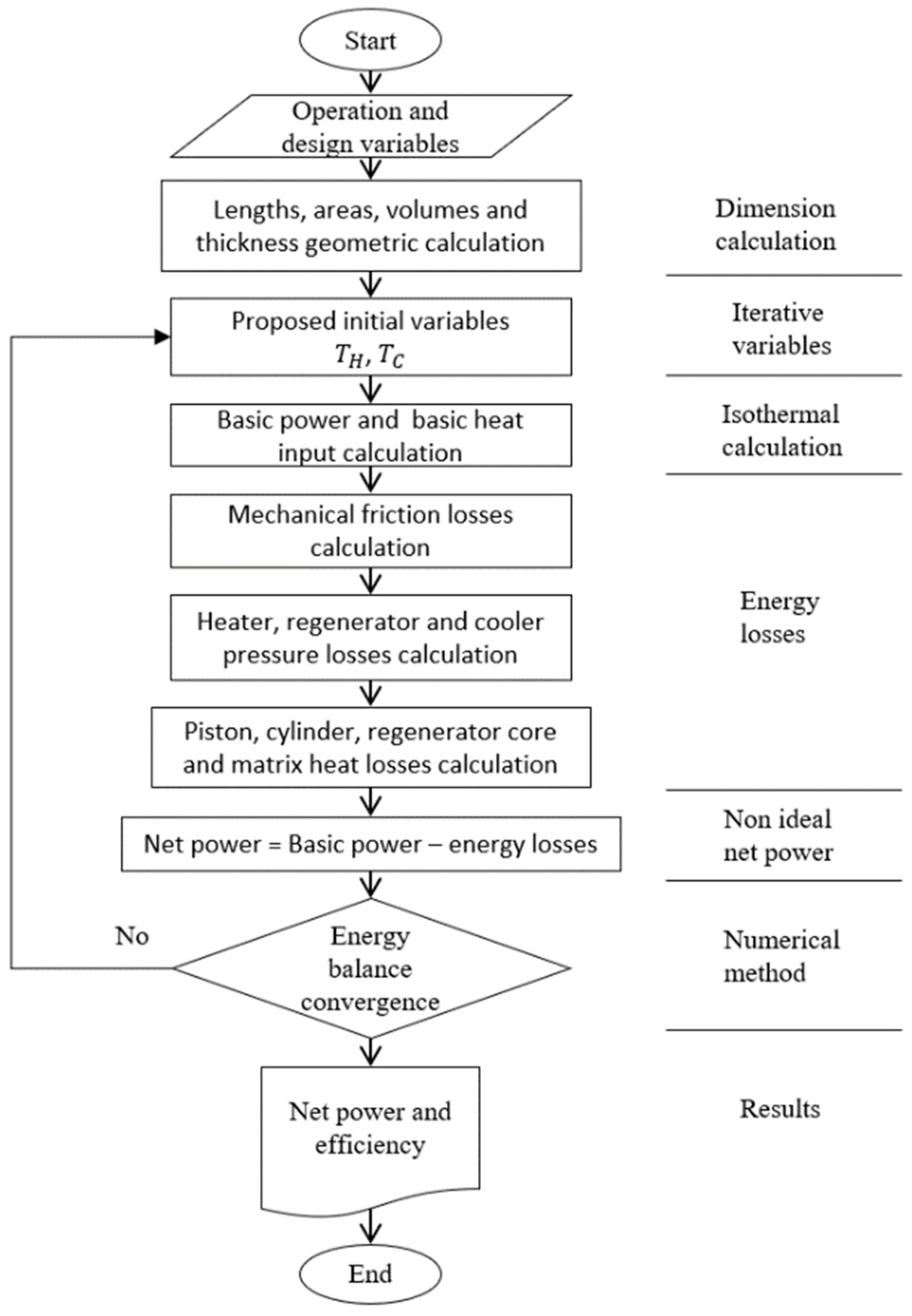
The performance of the Stirling engine, shown in Figure 1, is calculated in MATLAB (R2019a) using a second-order numerical model, following the flowchart in Figure 2. Net power and efficiency are determined using the method described by Martini [34] and a numerical approach. The model considers losses due to mechanical friction, pressure drops of the working fluid, and the main thermal losses of the engine in high-temperature zones.
The thermodynamic analysis of the engine is conducted by considering the volumes of the following components: expansion cylinder ( V H C y l ), expansion cylinder-heater connection ( V H S ), heater ( V H D ), regenerator ( V R ), compression cylinder-cooler connection ( V C S ), cooler ( V C D ), and compression cylinder ( V C C y l ). The expansion temperature ( T H ), regeneration temperature ( T R ), and compression temperature ( T C ) remain constant. The pressure is uniform across all components and varies as a function of the crankshaft angle ( ϴ ), as shown in the equation.
P ( ϴ ) = m R V H C Y L ( ϴ ) T H + V H D + V H S T H + V R T R + V C S + V C D T C + V C C Y L ( ϴ ) T C 1
The basic power of the engine ( B P ) is defined as the area under the P-V curve during one revolution and is given by:
B P = V r p m 60 ϴ = 1 360 P ( ϴ )
The basic heat input ( B H I ) is the minimum energy required to produce B P and is determined by:
B H I = B P 1 T C T H 1
The net power of the engine is calculated from B P by subtracting the energy losses due to mechanical friction and pressure drops in the heat exchangers.
N P = B P W P M F L
M F L is considered proportional to 20% of the basic power. The energy losses due to pressure drops, W P , include the losses in the heater ( W P H ), cooler ( W P C ), and regenerator ( W P R ):
W P H = 2   F C T W H S ρ P H
W P C = 2   F C T W C S ρ P C
W P R = 2   F C T W R S ρ P R
In the calculation of the pressure drops in the heater and cooler, an additional factor of 2.9 was considered, according to Chen and Griffin [35], resulting in the following equation:
P = 2   F   2.9   G 2 ρ L D
The pressure drop in the regenerator is represented by:
P R = F   G 2 2   ρ L R R H
The diameter of the heater and cooler tubes is usually small; therefore, the length-to-diameter ratio is large. As a result, the Fanning friction factor can be obtained by:
F =     l o g F = 16 / R e                                                             ,                     R e 2000 l o g F =   1.34 0.2 log R e   ,                                     R e > 2000
And the gas friction factor through the regenerator matrix is:
F r = l o g F r = 1.73 0.93 log R e r ,                                                   R e r < 60 l o g F r = 0.714 0.365 log R e r ,                     60 R e r < 60 l o g F r = 0.015 0.125 log R e r ,                                 R e r 1000
The heat flow required in the heater ( Q H ) is:
Q H = B H I + Q S + Q T S + Q R H W P H W P R / 2
where the static conduction heat losses ( Q S ) include the heat losses through the casing ( Q R , k ) and the regenerator matrix ( Q M X , k ), as well as through the piston crown ( Q P C , k ) and the expansion cylinder ( Q c y l , k ). These are determined, respectively, by:
Q R , k = k R   π D R , o D R , i 2 ( T H T C ) 4   L R
Q M X , k = k M X ( 0.25   π   D R , k 2 A H T , R ) ( T H T C ) L R
Q P C , k = π D H C Y L 2 k P C 4   L P C ( T H T C r a n k )
Q c y l , k = 0.25   π   k c y l D H C Y L , o 2 D H C Y L , i 2 1.33   P S
Assuming that heat transfer occurs when the total volume and the temperature of the regenerator matrix remain practically constant, and that only a small portion of the total volume is contained within the regenerator, the losses caused by overheating are calculated by:
Q T S = F C T   W R S C v T M X / 2
The losses in the regenerator due to imperfect regenerations are determined by:
Q R H = F C T   W R S C v T H T C 2 N T U r + 2
The number of transfer units (NTU) of energy from the heater, regenerator, and cooler to the gas is:
N T U = h x   A H T x 2   F C T   W x   C v
And since the Stirling engine is water-cooled, the Nusselt number for the shell-and-tube cooler depends on the Reynolds number and is given by Žukauskas [36]:
N u     N u = 1.04 R e 0.4 P r 0.36 P r / P r s 0.25                                               ,             0 R e < 500     N u = 0.71 R e 0.5 P r 0.36 P r / P r s 0.25                                               ,             500 R e < 1000 N u = 0.35 S t / S l 0.2 R e 0.6 P r 0.36 P r / P r s 0.25   ,             1000 R e < 2 × 10 5 N u = 0.31 S t / S l 0.2 R e 0.8 P r 0.36 P r / P r s 0.25   ,             2 × 10 5 R e < 2 × 10 6
The heat flow that needs to be removed in the cooler is:
Q C = Q H N P
Finally, the engine efficiency is calculated using the following expression:
η = N P / Q H
This numerical model was validated by Chen and Griffin [35], who reported that by correcting the gas friction factor with a factor of 2.9, the error in power and efficiency calculations was reduced by ±10%. The numerical model was also validated with experimental results from the GPU-3 engine, obtaining an average error of 5.7% for the heat input and 8.2% for the net power, respectively [37].

3.2. Determination of the Influence of System Variable Interactions on Efficiency

It is well known that, due to variable interactions, determining the optimal operating conditions of a system through a variable-by-variable parametric exploration is challenging. For this reason, the methodology used for exploring the 16 design variables (Table 1) is based on variable interactions or, in some cases, on the simultaneous parametric exploration of variable pairs.
In the present study, the operating conditions of the system—such as rotational speed, heat input, and ambient and boundary temperatures—are explicitly proposed a priori and kept fixed throughout the analysis. This definition of the operating conditions establishes a consistent reference framework for the exploration of the design space and ensures that the interaction analysis is performed under physically meaningful and representative operating scenarios. Under these prescribed conditions, efficiency was selected as the response parameter to characterize the interactions between the system design variables.
Variable interaction denotes the combined effect of both variables on system performance. Using the previously mentioned mathematical modeling or second-order simulator, various efficiency values were obtained through the simultaneous variation of variable pairs, generating response surfaces for each interaction.
First, the operating conditions are established in the second-order simulator for Alpha-type Stirling engines, including the supplied heat, revolutions per minute, ambient temperature, and material properties. Subsequently, an initial design of the Stirling engine is proposed, and the design variables that will interact must be selected.
Next, a simultaneous parametric exploration of variable pairs is carried out. This means that two variables must be selected for simultaneous parametric exploration, while the remaining 14 variables remain fixed at the values of the proposed initial design. Consequently, the efficiency calculation in the second-order simulator generates a response surface, which can be expressed as a function of two variables:
ɳ S i , j = f ( i , j , )
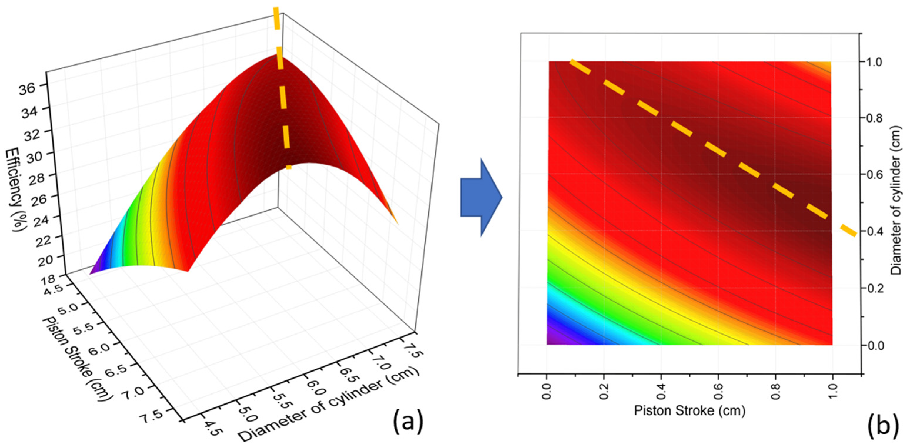
where f i , j , represents the system of equations for the thermal modeling of the Stirling engine. Similarly, i and j represent the vectors of the two selected variables, starting and ending at the lower and upper limits of their exploration range, obtaining ɳ S ( i , j ) as a response surface where the regions of highest efficiency are identified. Subsequently, the exploration ranges must be normalized, as shown in Figure 3, using Equation (24).
n o r m a l i z e d   v a r i a b l e   v a l u e   =   v a r i a b l e   v a l u e     l o w e r   l i m i t u p p e r   l i m i t     l o w e r   l i m i t  
Analyzing the trend of the set of high-efficiency points on the response surface ɳ S ( i , j ) ,   represented by an orange line in Figure 3a, indicates the existence of an optimal relationship between the interacting variables. This relationship is linearized using the least squares method (Figure 3), resulting in an equation of the following form:
j ɳ ( i ɳ ) =     i ɳ φ i + b i
where j ɳ represents the dimensionless value that the second selected variable must take to ensure maximum efficiency, as a function of the first selected variable i ɳ   (Figure 3b). Therefore, the slope φ i This process is repeated n i n i     1 times to develop all possible interactions among the 16 selected design variables, where n i represents the number of design variables. If the slope φ i is greater than 1, then the domain of the function j ɳ i ɳ is changed, and it is expressed as follows:
i ɳ ( j ɳ ) = j ɳ φ j + b j
In this way, φ j is now less than 1. The reason for this adjustment is that the quantification of the interaction does not require identifying which variable has the greatest influence on the efficiency of system. Instead, the goal is simply to determine whether an interaction between the variables exists and how strong it is.
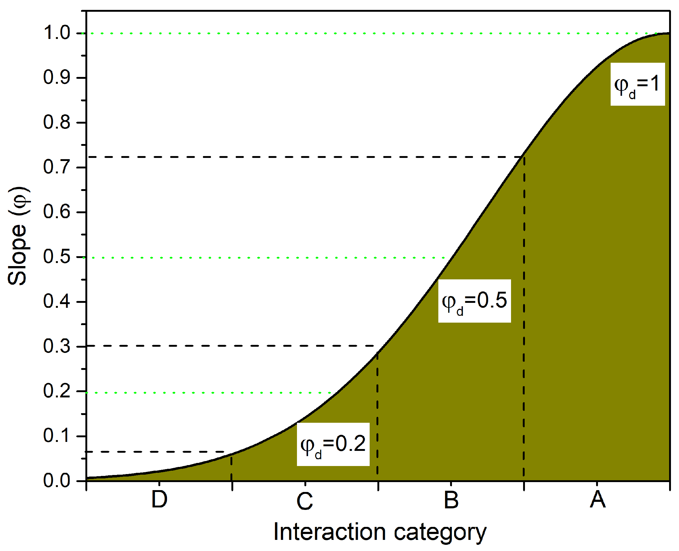
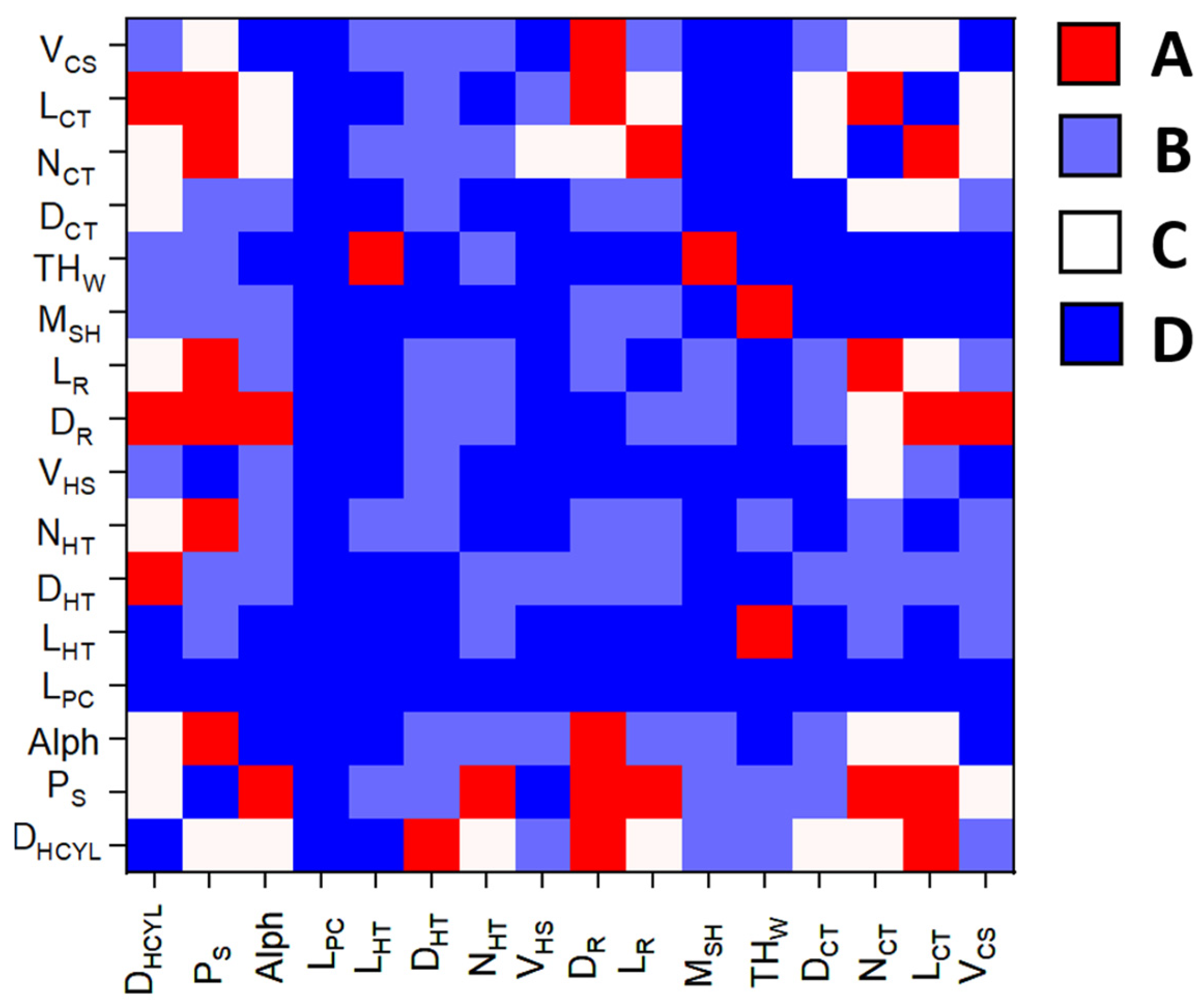
Subsequently, the interactions must be categorized. Figure 4 presents the function used to classify the resulting values of φ (from Equation (25) or Equation (26), as applicable) into the four proposed categories: strong (A), significant (B), weak (C), and null (D). If the slope ( φ ) falls within the null zone (D), it indicates that only one of the selected variables modifies the conditions to determine the maximum efficiency, meaning that no interaction exists. On the other hand, if the slope φ falls within the strong zone (A), it means that both selected variables influence efficiency with similar effects, indicating a strong interaction.
Once the interactions have been categorized, the global interaction scheme of the system is developed, consisting of a 16 × 16 matrix of φ values. In this matrix, the diagonal line indicates non-permitted interactions, as a variable cannot interact with itself, as shown in Table 2. Subsequently, the φ d values from each row are summed, meaning:
Φ i = y = 1 y = 16 φ ( i , j )
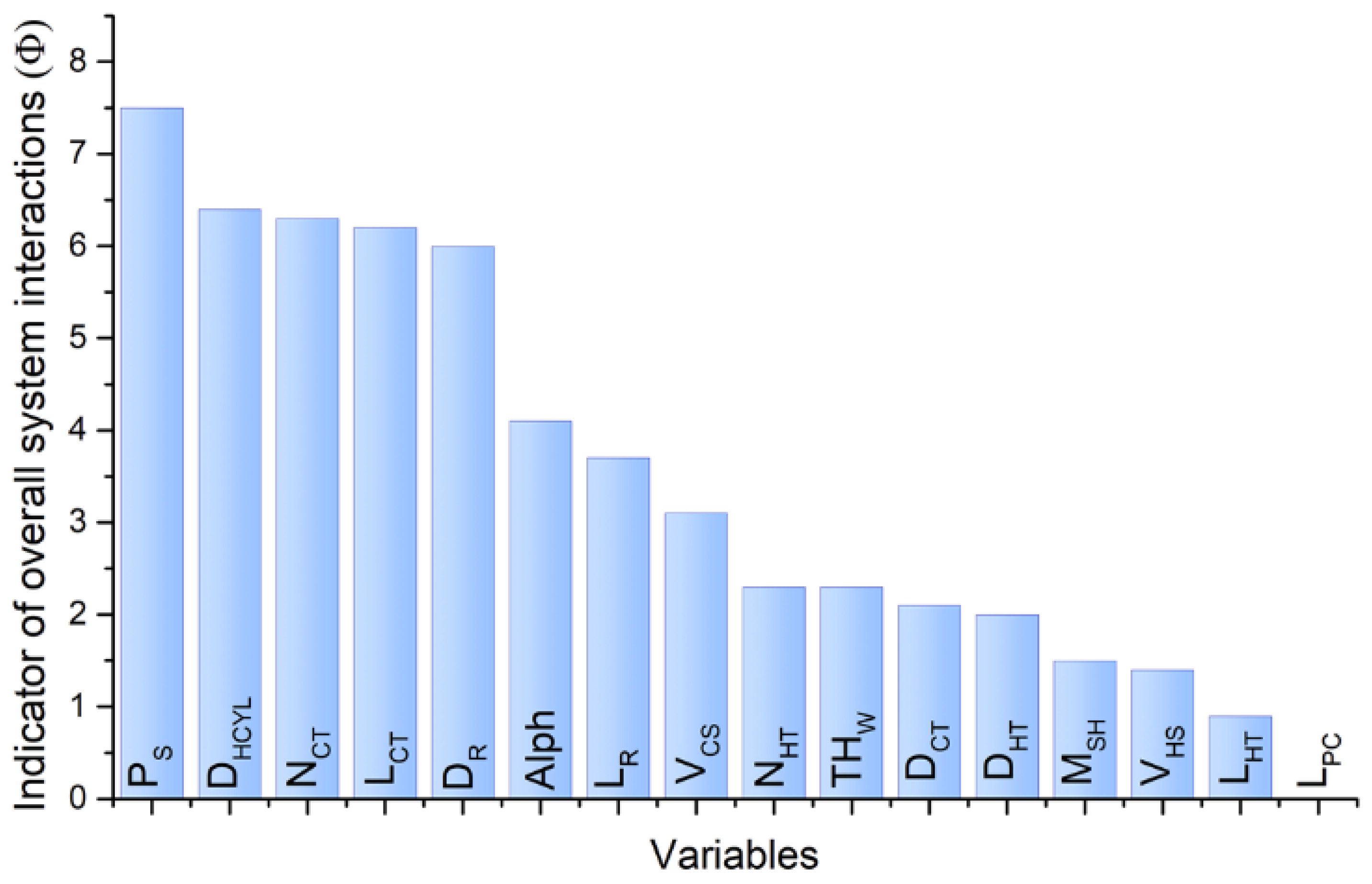
Figure 5 shows the results of the Global Scheme of System Interactions represented as a heatmap, where interactions are visualized based on their respective categories. In addition, the global interaction indicator of the system ( Φ n i )   , quantitatively describes the interaction of a variable with the rest of the variables in terms of its influence on the system. In other words, it indicates how much a given variable affects the performance of other variables or subsystems. Subsequently, the Φ n i indicators are sorted in descending order according to their magnitude, allowing for the establishment of the hierarchy of system variables, as shown in Figure 6.
It is observed that the piston stroke ( P S ) is the variable with the greatest influence on the system design, as it interacts with 11 variables, 7 of which fall into the strong interaction category. This is because P S directly affects the swept volume, mass flow rate, and maximum basic power. Therefore, modifying this variable impacts the performance of the other components and should be optimized together with the cylinder diameter, as this pair of variables holds the highest hierarchy.

3.3. Pairwise Variable Optimization Method

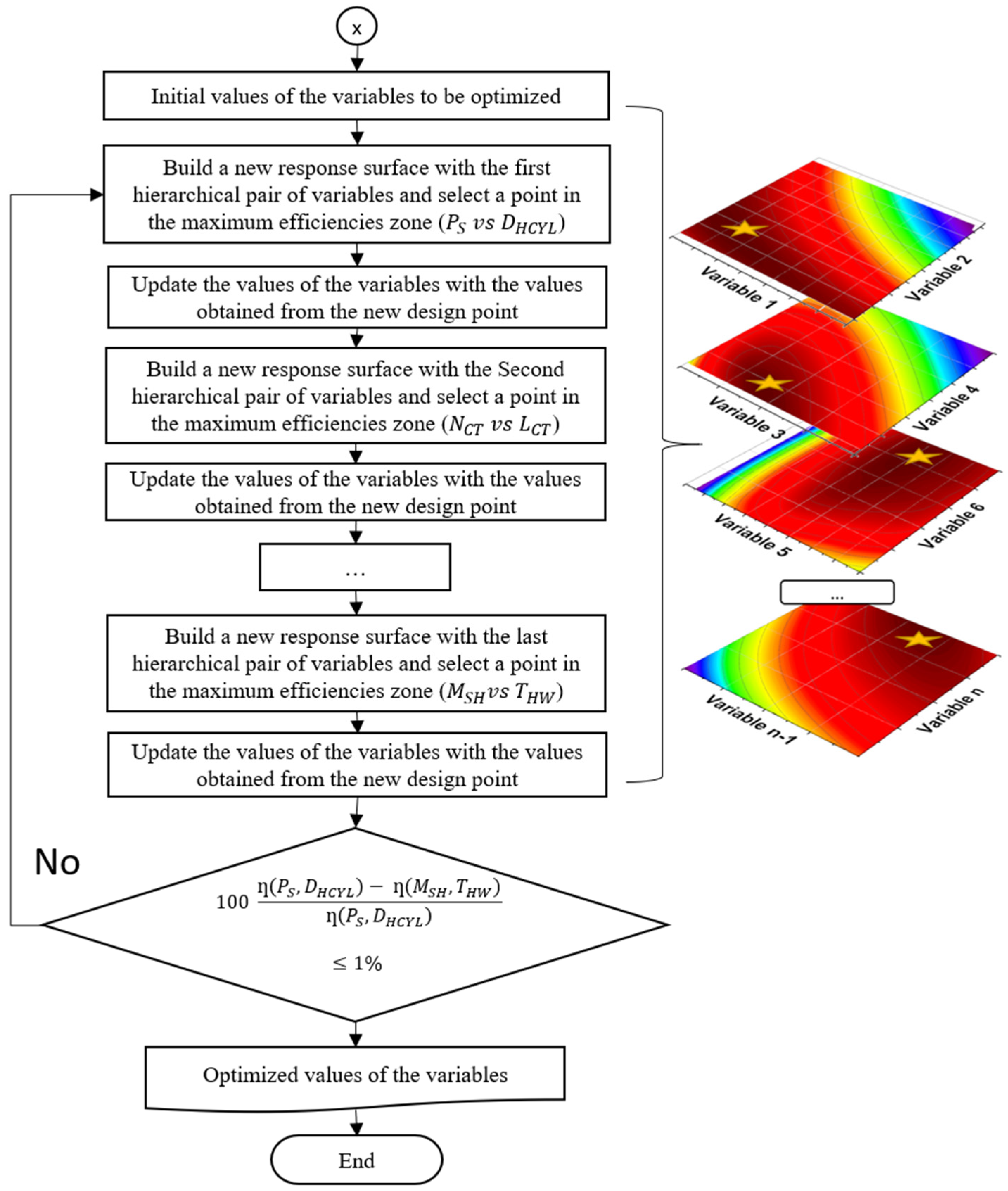
A pairwise variable optimization method is proposed using the variable hierarchy (Figure 6), which follows a series of steps outlined in the flowchart in Figure 7. Essentially, the hierarchy helps determine which pair of variables should be optimized first and which should be optimized last in an iterative process.
Starting from an initial design and given operating conditions of the Stirling engine, the iterative process begins with the highest-ranking pair of variables. For the Alpha-type Stirling engine system, the highest-ranking pair is the piston stroke ( P S ) and the cylinder diameter ( D H C Y L ). The design point with the highest efficiency on this response surface is selected. Subsequently, the system design variables are updated, and a new response surface is generated with the next highest-ranking pair of variables, in this case, N C T and L C T .
This process is repeated until the increase in efficiency between the current and previous iteration is less than or equal to 0.5%, thereby obtaining the optimal values for the design variables of the system.
The explored variable pairs were P S   v s .   D H C Y L , N T C vs. L C T , D R   v s .   V C S , A l p h   v s .   L R , D H T   v s .   N H T and M S H   v s .   T H W , in that order (Figure 6), as indicated by the variable hierarchy. The default values and the exploration ranges for each of the studied variables are shown in Table 1.

4. Discussion of Results

This section discusses the effect of certain variables that, when combined, can improve system performance. It also highlights how one of the studied variables has a direct and individual influence on system performance. Additionally, the functionality of the proposed methodology, referred to as guided pairwise variable optimization, is presented and compared to an alternative approach called guided univariate optimization. Finally, the operational performance of three Stirling engines is analyzed: the initial design, the G.U.I.O. design, and the G.I.P.O. design.

4.1. Analysis of Interactions and the Hierarchization of System Variables

Using the main design variables of an Alpha-type Stirling engine, a simultaneous exploration of variable pairs was conducted in a second-order numerical simulator on the MATLAB platform (R2019a), obtaining various response surfaces for system efficiency. These surfaces were studied and analyzed as described in Section 3.2, allowing for a qualitative and quantitative determination of the combined effect that the studied variables have on system efficiency.
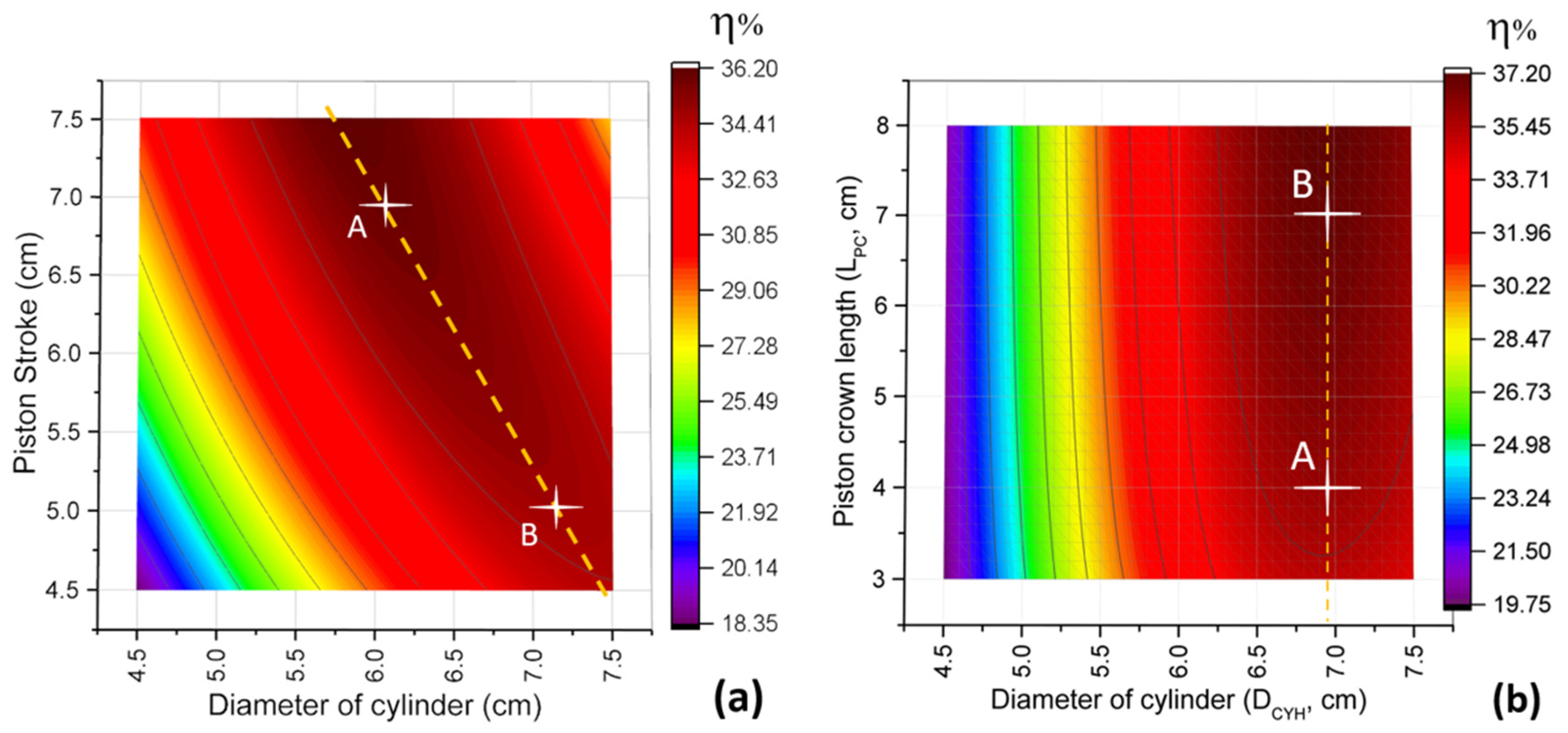
Figure 8a presents an interaction categorized as strong, resulting from the combined effect of piston stroke and cylinder diameter. This can also be expressed through the dependency between these variables, meaning that the piston stroke value is a function of the cylinder diameter, leading to an improvement in system efficiency. For example, if we observe design point B, where the piston stroke is 5 cm, the highest efficiency is achieved with a cylinder diameter of 7.2 cm. However, based on the same relationship between these variables, other design points with better efficiency can be determined, such as point A. Starting from the initial design, this relationship can be described as inversely proportional, since decreasing the cylinder diameter requires a greater piston stroke than that of the initial design, thus increasing system efficiency.
On the other hand, Figure 8b illustrates the combined effect of the cylinder diameter and the length of the piston crown (hot side) as an example of an interaction categorized as null. It can be observed that, regardless of the cylinder length, the design points with the highest efficiency occur when the cylinder diameter is 7 cm. This indicates the independence between these variables or, in other words, shows that they are orthogonal variables (graphically). However, the individual influence of the piston crown length on system efficiency is significant, showing increases of up to 0.25% per additional centimeter.

4.2. System Performance Optimization

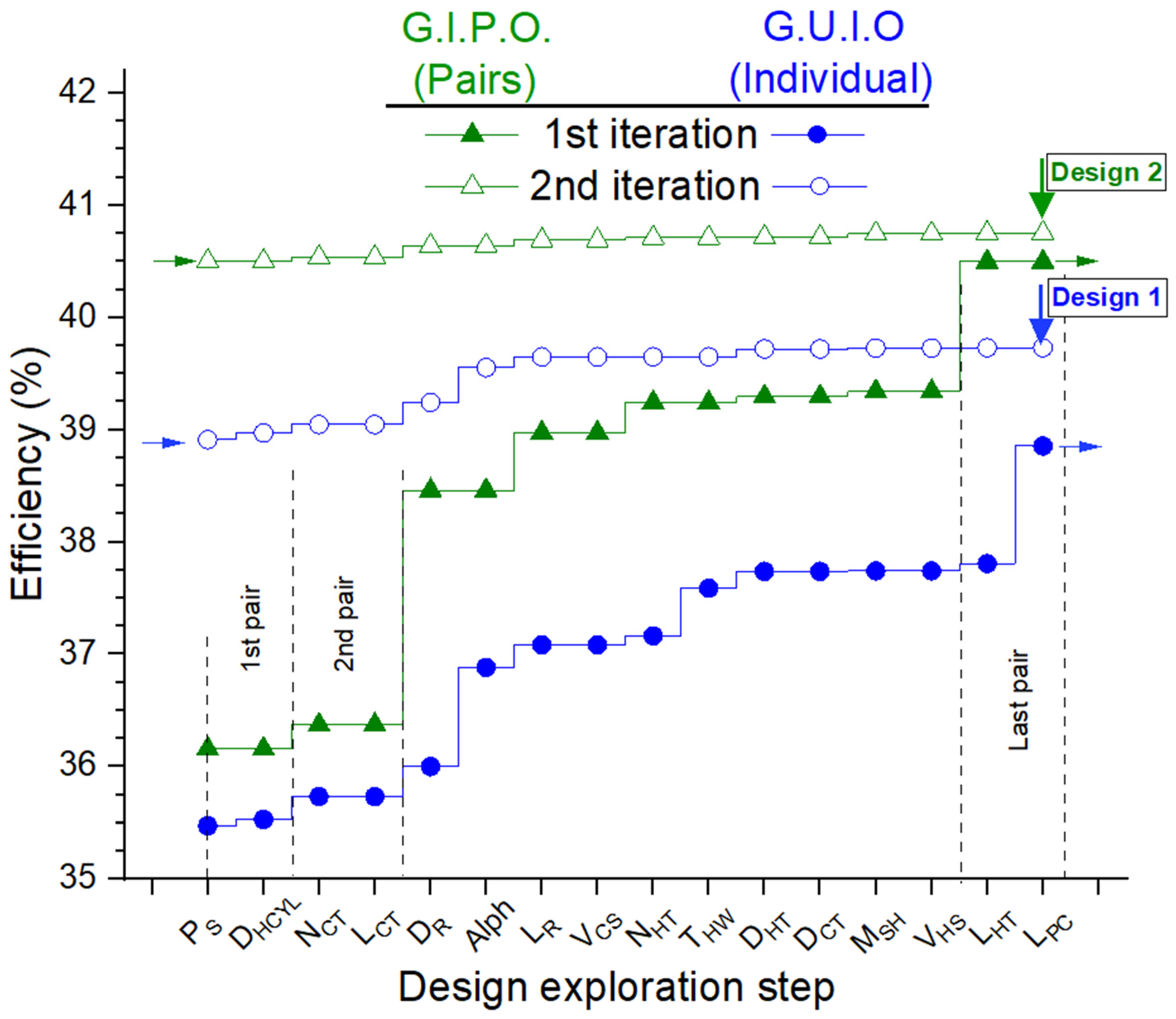
The objective of this study is to present the steps or guidelines for optimizing an Alpha-type Stirling engine through a guided parametric exploration of variable pairs to improve system performance. The Figure 9 illustrates the efficiency increase at each step of the guided exploration for both the proposed guided pairwise variable optimization (G.I.P.O.) method and the guided univariate optimization (G.U.I.O.) approach. It is important to note that once the first iteration, or the first guided parametric exploration, is completed, the parametric exploration can be restarted by implementing the design values obtained from the first iteration. Analyzing the first iteration, it is observed that after exploring the first two pairs of variables ( P S   v s .   D H C Y L and N C T   v s .   L C T ) and determining the best operating points, efficiency increases by approximately 0.4%. However, when exploring the third pair ( D R   v s .   A l p h a ) and determining the new operating point, efficiency increases significantly by 2.01%.
This improvement is mainly due to the new design point of the variable Alpha, which decreased from 90° to 52° in this first iteration. Similarly, in the univariate exploration, the same behavior can be observed, where Alpha is reduced from 90° to 64° in the first iteration.
It is important to mention that the improvement in efficiency may be due to the selection of the new design point for the explored variable pair or to the individual influence of one of the explored variables. For example, analyzing the first iteration, it is observed that the new design point of the piston crown length ( L P C ) improves efficiency by 1.05% in the case of univariate exploration. On the other hand, for the guided pairwise variable exploration, efficiency increases by 1.15% due to the combined effect of the heater tube length and the piston crown length ( L H T   v s .   L P C ).
Although the difference between the efficiencies of the designs generated by both approaches is only 1.64% in the first iteration, it is worth noting that the guided pairwise variable exploration achieves a better result with half the steps required by the univariate exploration.
Table 3 presents the values of the variables for the initial design, the design resulting from univariate exploration, and the design obtained through guided pairwise variable exploration. It is observed that system efficiency increases by 4.55% and 3.53% in the resulting designs from G.I.P.O. and G.U.I.O., respectively.
Additionally, it is important to mention that, based on their observed trends, the variables V H S and V C S should be minimized to ensure maximum system efficiency. In contrast, L P C should be maximized to reduce heat conduction losses through the hot piston to the crankcase of the Stirling engine.
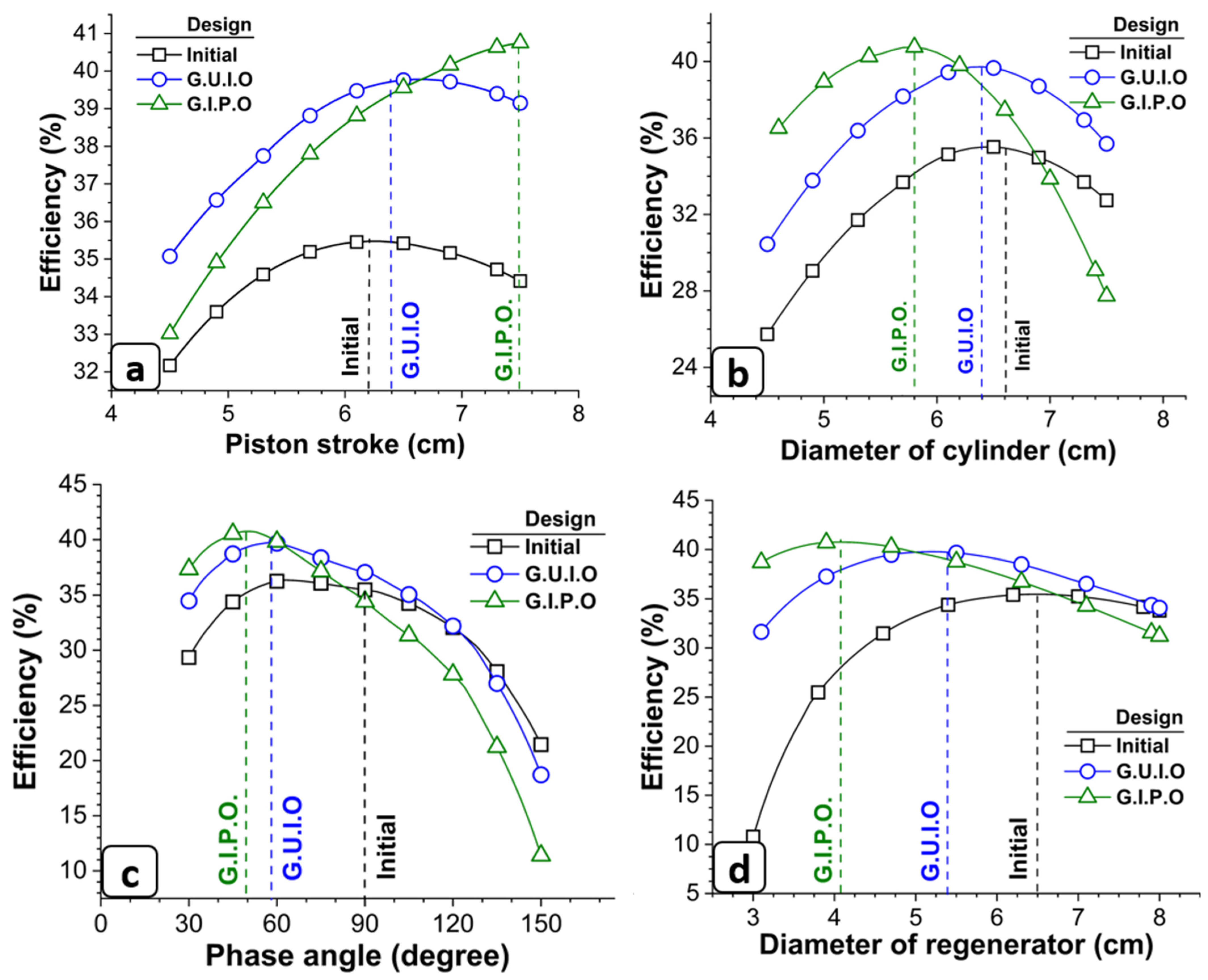
Figure 10 presents four of the sixteen design variables studied in this work and illustrates their individual influence on system efficiency for both the initial Stirling engine design and the optimized proposals (Table 3).
For example, Figure 10a shows the variation of the piston stroke from the initial design, where it is evident that the maximum efficiency occurs at P S   = 6.2 cm. Therefore, further improvement in design efficiency is not possible with this parametric exploration. However, in the G.U.I.O. proposal, the maximum efficiency is observed at P S = 6.6 cm, but this result would only be achieved in the third iteration. Since only two iterations were performed, the proposed P S value obtained was 6.4 cm. On the other hand, the behavior of the G.I.P.O. proposal indicates that the longer the piston stroke, the higher the efficiency. The final stroke value reached was 7.5 cm, limited by the exploration boundaries.
In Figure 10b, it is shown that under these design conditions, the values of D H C Y L = 5.8 cm and D H C Y L = 6.4 cm correspond to the maximum efficiency for G.I.P.O. and G.U.I.O., respectively. In contrast, for the initial design proposal, the maximum efficiency does not correspond to the initial cylinder diameter value.
On the other hand, Figure 10c presents the exploration of the phase angle Alpha, where A l p h a = 90° in the initial design, as stated in the original design of an Alpha-type Stirling engine according to the literature. However, control systems based on varying this angle have been proposed. Under these operating conditions, it is observed that the initial design achieves higher efficiency at A l p h a   =   60 ° . Consequently, it is expected that the G.U.I.O. design proposal would take approximately this value. Similarly, the design proposed by G.I.P.O. results in A l p h a   <   90 ° .
It is worth mentioning that if we analyze the behavior of these explorations with Alpha = 90°, the G.U.I.O. proposal shows higher efficiency compared to both the initial design and the G.I.P.O. design.
The regenerator diameter is included in the third pair of explored variables and significantly influences energy losses associated with pressure drops, thermal conduction, overheating, and the overall regeneration capacity of the system. Figure 10d presents the exploration of the regenerator diameter, showing that the initial design achieves maximum efficiency at D R = 6.5 cm, indicating an appropriate selection of the regenerator diameter based on a previous parametric study. However, since the variables P S   , D H C Y L , N T C , L C T , and Alpha were not properly selected, it can be observed that for diameters smaller than 4.5 cm, efficiency decreases significantly.
In contrast, for the G.I.P.O. design proposal, the regenerator diameter that provides the highest efficiency is 4.1 cm, with a noticeable decrease only for diameters greater than 6.75 cm. However, the G.U.I.O. design proposal shows better efficiency than the initial design across all explored values of D R .
Based on the analysis of the variables in Figure 10, it was determined that the design proposed by G.I.P.O. has appropriately selected P S , D H C Y L , A l p h a , and D R .
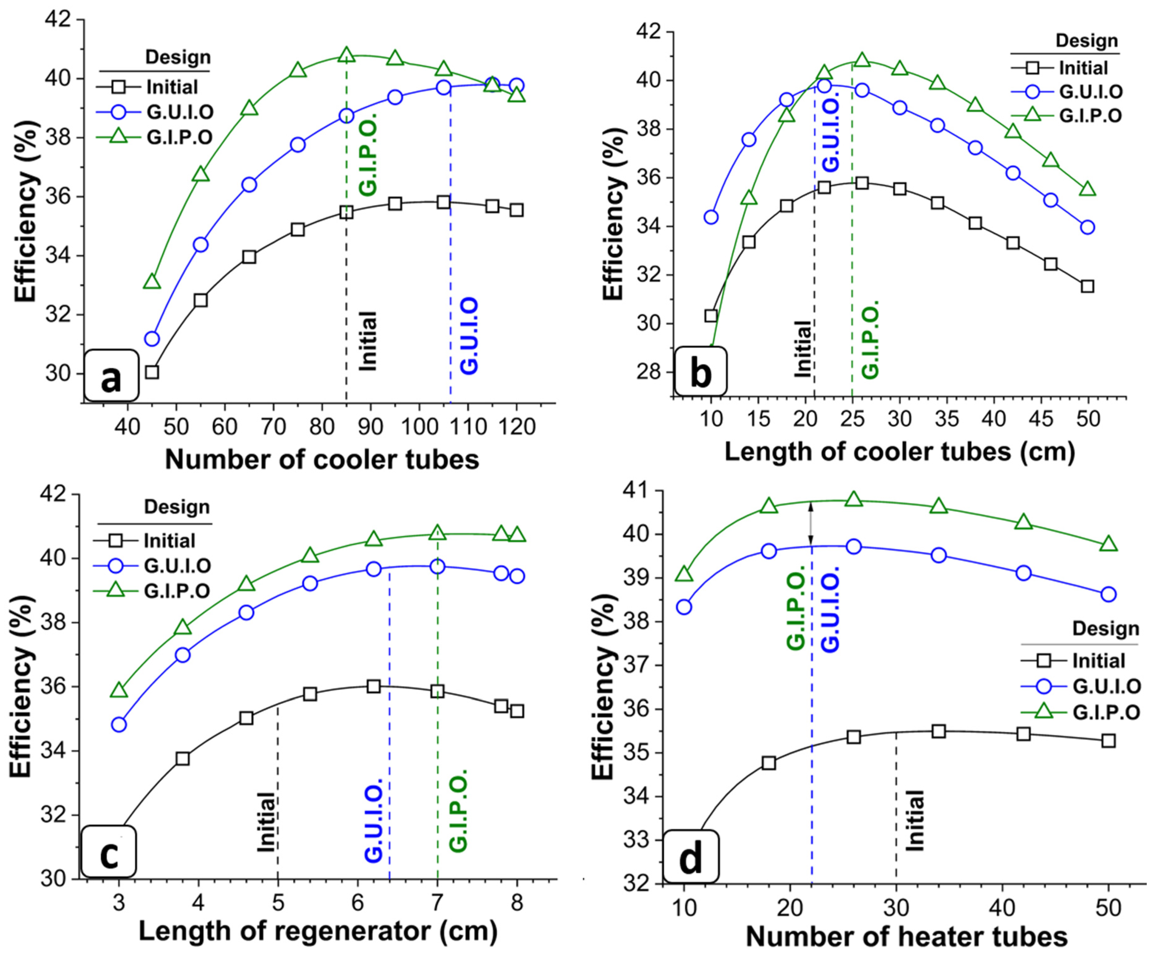
The next pair of explored variables corresponds to N T C and L T C , which are specific to the cooler of the Stirling engine. Figure 11a presents the exploration of the number of cooler tubes, where the initial design shows that the selected value does not result in maximum efficiency. Instead, with approximately 100 tubes, efficiency increases by 0.45%. Thus, it is expected that the G.U.I.O. design will select N T C = 106, as the previously selected values of P S and D H C Y L are similar to those in the initial proposal. However, in the G.I.P.O. design, where the piston stroke is at its maximum within the exploration range, the selected value is N T C = 85. This coincides with the initial design, but in this case, the efficiency is indeed maximized.
On the other hand, Figure 11b presents the exploration of the cooler tube length, where the initial design with L C T = 21 cm indicates that efficiency can be improved by increasing this length. It is important to note that although the initial design values of N T C and L T C do not correspond to the maximum efficiency under these conditions, they still yield excellent results for the other design proposals.
The exploration of the regenerator length is shown in Figure 11c. Similar to the variables L C T , N C T , and A l p h a , it is evident that the initial design value does not yield maximum efficiency under these operating conditions. However, the G.U.I.O. method suggests maintaining L R at 6.4 cm, which increases efficiency by 3.53%. In contrast, modifying L R to 6.4 cm in the initial design would only result in a 0.52% efficiency increase.
Additionally, In the Figure 11d, it is shown that both the G.U.I.O. and the G.I.P.O. methods recommend reducing the number of heater tubes ( N H T ) from 30 to 22, which increases efficiency to 3.53% and 4.55%, respectively.

4.3. Operational Performance of the Studied Designs

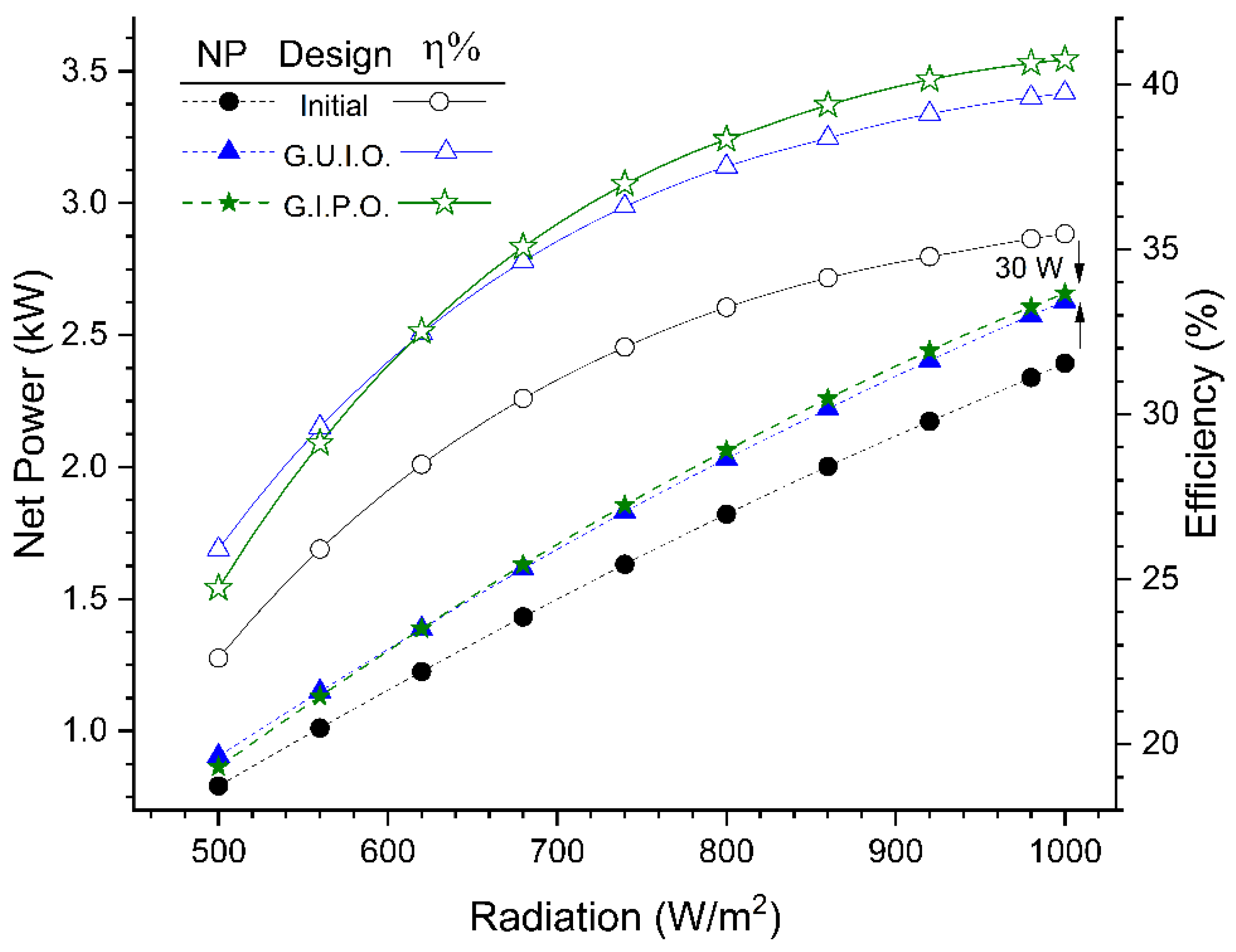
To evaluate whether the proposed designs exhibit improved performance under different operating conditions, an exploration was conducted based on the heat input of the Stirling engine. The heat input was analyzed by varying the irradiance (W/m2), as shown in the Figure 12. It was determined that both the efficiency and net power of the initial Stirling engine design are lower than those obtained from the proposed designs. Additionally, it was observed that for irradiance levels below 620 W/m2, the net power and efficiency of the design resulting from the G.U.I.O. method are higher than those of the design proposed by the G.I.P.O. methodology.
The performance of the Stirling engine, as a heat engine, is governed by Carnot efficiency, meaning that both its efficiency and power increase proportionally with heat input. It was observed that at an irradiance of 1000 W/m2, the net power of the Stirling engine designed using the G.I.P.O. methodology improves by 30 W.
Additionally, efficiency increases by 1.02% compared to the G.U.I.O. design and by 4.55% compared to the initial design.

5. Conclusions

This study proposes a methodology for optimizing Alpha-type Stirling engines based on the analysis of interactions between pairs of variables. This methodology, referred to as Guided Pairwise Variable Optimization (G.I.P.O.), has proven to be an efficient and practical tool for improving the theoretical performance of these systems through the use of a second-order numerical simulator. The methodology allows for the identification of the variables that most influence system efficiency, as well as the weighting of their interactions. By hierarchizing the interaction indicators, the optimization process achieves more effective configurations in fewer iterations.
Compared to the Guided Univariate Optimization (G.U.I.O.) method, G.I.P.O. achieves significant efficiency improvements, reaching a 4.55% increase compared to the 3.53% obtained with G.U.I.O. However, it is important to note that both approaches are guided by the hierarchy of interaction indicators.
The analysis reveals that variables such as cylinder diameter and piston stroke have a critical impact on system performance, not only due to their direct influence but also because of their interaction with other subsystems. Additionally, increasing the piston crown length improves efficiency individually, despite not exhibiting strong or significant interactions with other variables.
Finally, the optimized designs were simulated under various operating conditions, demonstrating significant improvements in efficiency and net power compared to the initial design, particularly when radiation exceeds 620 W/m2. It is important to highlight that the objective of this methodology is to guide the user through a set of parametric explorations of their system to determine the best configuration without the need for advanced optimization techniques.

Author Contributions

Conceptualization, S.I.-P., R.B.-C. and R.L.-Z.; methodology, S.I.-P. and R.B.-C.; software, S.I.-P.; investigation, S.I.-P.; writing—original draft, S.I.-P.; writing—review & editing, N.V.-L., R.B.-C., J.A.A.-J. and R.L.-Z.; supervision, S.I.-P. and N.V.-L.; project administration, S.I.-P. All authors have read and agreed to the published version of the manuscript.

Funding

This research received no external funding.

Data Availability Statement

The data presented in this study are available on request from the corresponding author.

Conflicts of Interest

The authors declare no conflict of interest.

Abbreviations

The following abbreviations are used in this manuscript:
SymbolDescription
A Transversal   area ,   c m 2
A l p h a Phase angle, degree
B H I basic heat input, W
B P Basic power, W
C v Heat capacity, J/kg °C
D Diameter, cm
F Fanning friction factor
F C T   Time fraction
F r Friction factor
k Thermal conductivity coefficient
L Length, cm
m Mass, kg
M F L Losses due friction, W
M S H Mesh size, w i r e s / c m
N Number of
N P Net power, W
N T U number of transfer units
N u Nusselt number
P Pressure, MPa
P r Prandtl number
P S Piston stroke, cm
Q c y l , k heat losses through the expansion cylinder, W
Q M X , k heat losses through the regenerator matrix, W
Q P C , k heat losses through the piston crown, W
Q R H losses in the regenerator due to imperfect regenerations, W
Q R , k heat losses through the casing, W
Q S static conduction heat losses, W
Q T S losses caused by overheating
R Gas constant
R e Reynolds number
T Temperature, K
T H W Wire thickness in the mesh, cm
V C D Dead   volume   of   the   cooler ,   c m 3
V C S Extra   dead   volume   in   the   compression   zone ,   c m 3
V H D Heater   dead   volume ,   c m 3
V H S Extra   dead   volume   in   the   expansion   zone ,   c m 3
V R Dead   volume   of   regenerator ,   c m 3
V r p m Revolutions of crankshaft, rpm
V S W Swept volume, c m 3
W P energy losses due to pressure drops, W
Greeks
ϴ Crankshaft position, degree
η Efficiency, %
ρ Density, k g / c m 3
ƞ s Thermal efficiency response surface
φ Interaction grade of the variable pair
subscripts
C C Y L Compression cylinder
C T Tubes of the cooler.
H C Y L Expansion cylinder
H Heater
H T Tubes of the heater.
P C Piston crown
R Regenerator

References

  1. Bert, J.; Chrenko, D.; Sophy, T.; Le Moyne, L.; Sirot, F. Simulation, experimental validation and kinematic optimization of a Stirling engine using air and helium. Energy 2014, 78, 701–712. [Google Scholar] [CrossRef] [Scilit]
  2. Colmenar-Santos, A.; Zarzuelo-Puch, G.; Borge-Diez, D.; García-Diéguez, C. Thermodynamic and exergoeconomic analysis of energy recovery system of biogas from a wastewater treatment plant and use in a Stirling engine. Renew. Energy 2016, 88, 171–184. [Google Scholar] [CrossRef] [Scilit]
  3. Marion, M.; Louahlia, H.; Gualous, H. Performances of a CHP Stirling system fuelled with glycerol. Renew. Energy 2016, 86, 182–191. [Google Scholar] [CrossRef] [Scilit]
  4. Beltrán-Chacon, R.; Leal-Chavez, D.; Sauceda, D.; Pellegrini-Cervantes, M.; Borunda, M. Design and analysis of a dead volume control for a solar Stirling engine with induction generator. Energy 2015, 93, 2593–2603. [Google Scholar] [CrossRef] [Scilit]
  5. Chen, M.; Ju, Y.L. Effect of different working gases on the performance of a small thermoacoustic Stirling engine. Int. J. Refrig. 2015, 51, 41–51. [Google Scholar] [CrossRef] [Scilit]
  6. Kazimierski, Z.; Wojewoda, J. Comparison of the externally heated air valve engine and the helium Stirling engine. Energy Convers. Manag. 2014, 80, 357–362. [Google Scholar] [CrossRef] [Scilit]
  7. Catapano, F.; Frazzica, A.; Freni, A.; Manzan, M.; Micheli, D.; Palomba, V.; Sementa, P.; Vaglieco, B.M. Development and experimental testing of an integrated prototype based on Stirling, ORC and a latent thermal energy storage system for waste heat recovery in naval application. Appl. Energy 2022, 311, 118673. [Google Scholar] [CrossRef] [Scilit]
  8. Araoz, J.A.; Cardozo, E.; Salomon, M.; Alejo, L.; Fransson, T.H. Development and validation of a thermodynamic model for the performance analysis of a gamma Stirling engine prototype. Appl. Therm. Eng. 2015, 83, 16–30. [Google Scholar] [CrossRef] [Scilit]
  9. de Moura, E.F.; Henriques, I.B.; Ribeiro, G.B. Thermodynamic-Dynamic coupling of a Stirling engine for space exploration. Therm. Sci. Eng. Prog. 2022, 32, 101320. [Google Scholar] [CrossRef] [Scilit]
  10. Dai, D.; Yuan, F.; Long, R.; Liu, Z.; Liu, W. Performance analysis and multi-objective optimization of a Stirling engine based on MOPSOCD. Int. J. Therm. Sci. 2018, 124, 399–406. [Google Scholar] [CrossRef] [Scilit]
  11. Rutczyk, B.; Szczygieł, I.; Kabaj, A. Evaluation of an α type stirling engine regenerator using a new differential model. Energy 2020, 209, 118369. [Google Scholar] [CrossRef] [Scilit]
  12. Qiu, H.; Wang, K.; Yu, P.; Ni, M.; Xiao, G. A third-order numerical model and transient characterization of a β-type Stirling engine. Energy 2021, 222, 119973. [Google Scholar] [CrossRef] [Scilit]
  13. Getie, M.Z.; Lanzetta, F.; Bégot, S.; Admassu, B.T.; Djetel-Gothe, S. A non-ideal second order thermal model with effects of losses for simulating beta-type Stirling refrigerating machine. Int. J. Refrig. 2021, 130, 413–423. [Google Scholar] [CrossRef] [Scilit]
  14. Bataineh, K.M.; Maqableh, M.F. A new numerical thermodynamic model for a beta-type Stirling engine with a rhombic drive. Therm. Sci. Eng. Prog. 2022, 28, 101071. [Google Scholar] [CrossRef] [Scilit]
  15. Ahmed, F.; Zhu, S.; Yu, G.; Luo, E. A potent numerical model coupled with multi-objective NSGA-II algorithm for the optimal design of Stirling engine. Energy 2022, 247, 123468. [Google Scholar] [CrossRef] [Scilit]
  16. Li, R.; Grosu, L.; Li, W. New polytropic model to predict the performance of beta and gamma type Stirling engine. Energy 2017, 128, 62–76. [Google Scholar] [CrossRef] [Scilit]
  17. West, C.D. Principles and Applications of Stirling Engines, 1st ed.; Van Nostrand Reinhold: New York, NY, USA, 1986. [Google Scholar]
  18. Jan, W.; Marek, P. Mathematical Modeling of the Stirling Engine. Procedia Eng. 2016, 157, 349–356. [Google Scholar] [CrossRef] [Scilit]
  19. Babaelahi, M.; Sayyaadi, H. Modified PSVL: A second order model for thermal simulation of Stirling engines based on convective–polytropic heat transfer of working spaces. Appl. Therm. Eng. 2015, 85, 340–355. [Google Scholar] [CrossRef] [Scilit]
  20. Tlili, I.; Musmar, S.A. Thermodynamic evaluation of a second order simulation for Yoke Ross Stirling engine. Energy Convers. Manag. 2013, 68, 149–160. [Google Scholar] [CrossRef] [Scilit]
  21. Almajri, A.K.; Mahmoud, S.; Al-Dadah, R. Modelling and parametric study of an efficient Alpha type Stirling engine performance based on 3D CFD analysis. Energy Convers. Manag. 2017, 145, 93–106. [Google Scholar] [CrossRef] [Scilit]
  22. Xu, H.; Chen, L.; Ge, Y.; Feng, H. Multi-objective optimization of Stirling heat engine with various heat and mechanical losses. Energy 2022, 256, 124699. [Google Scholar] [CrossRef] [Scilit]
  23. Prajapati, P.; Patel, V.; Raja, B.D.; Jouhara, H. Multi objective ecological optimization of an irreversible Stirling cryogenic refrigerator cycle. Energy 2023, 274, 127253. [Google Scholar] [CrossRef] [Scilit]
  24. Eser, S.; Yuce, B.E. A metaheuristic approach for multi-objective optimization of the Stirling cycle with internal irreversibilities and regenerative losses using artificial bee colony algorithm. Energy Convers. Manag. 2023, 292, 117372. [Google Scholar] [CrossRef] [Scilit]
  25. Solmaz, H.; Karabulut, H. Performance comparison of a novel configuration of beta-type Stirling engines with rhombic drive engine. Energy Convers. Manag. 2014, 78, 627–633. [Google Scholar] [CrossRef] [Scilit]
  26. Ye, W.; Wang, W.; Zhu, J.; Liu, Y. Optimizing design of a free piston Stirling engine using response surface methodology and grey relation analysis. Case Stud. Therm. Eng. 2024, 54, 103981. [Google Scholar] [CrossRef] [Scilit]
  27. Rahmati, A.; Varedi-Koulaei, S.M.; Ahmadi, M.H.; Ahmadi, H. Dimensional synthesis of the Stirling engine based on optimizing the output work by evolutionary algorithms. Energy Rep. 2020, 6, 1468–1486. [Google Scholar] [CrossRef] [Scilit]
  28. Chen, P.; Deng, C.; Luo, X.; Ye, W.; Hu, L.; Wang, X.; Liu, Y. Performance optimization of a free piston Stirling engine using the self-directed online machine learning optimization approach. Appl. Therm. Eng. 2024, 236, 121482. [Google Scholar] [CrossRef] [Scilit]
  29. Gholamian, E.; Seyed Mahmoudi, S.M.; Balafkandeh, S. Techno-economic appraisal and machine learning-based gray wolf optimization of enhanced fuel cell integrated with stirling engine and vanadium-chlorine cycle. Int. J. Hydrogen Energy 2024, 51, 1227–1241. [Google Scholar] [CrossRef] [Scilit]
  30. Masoumi, A.P.; Tavakolpour-Saleh, A.R.; Bagherian, V. Performance investigation of an active free-piston Stirling engine using artificial neural network and firefly optimization algorithm. Heliyon 2024, 10, e28387. [Google Scholar] [CrossRef] [Scilit] [PubMed]
  31. Yang, H.-S.; Cheng, C.-H. Development of a beta-type Stirling engine with rhombic-drive mechanism using a modified non-ideal adiabatic model. Appl. Energy 2017, 200, 62–72. [Google Scholar] [CrossRef] [Scilit]
  32. Ergin, T. Experimental optimization of displacer working gap in a gamma-type Stirling engine. Eng. Sci. Technol. Int. J. 2024, 52, 101677. [Google Scholar] [CrossRef] [Scilit]
  33. Sheykhi, M.; Mehregan, M. Comprehensive technical and economic study and optimization of a novel combined cooling heating and power system driven by a four cylinder α type Stirling engine. Appl. Therm. Eng. 2024, 236, 121869. [Google Scholar] [CrossRef] [Scilit]
  34. Martini, W.R. Stirling Engine Design Manual, 2nd ed.; DOE/NASA/3194-1; NASA CR-168088; National Aeronautics and Space Administration, Lewis Research Center: Cleveland, OH, USA, 1983.
  35. Chen, N.C.J.; Griffin, F.P. A Review of Stirling Engine Mathematical Models; Oak Ridge National Laboratory (ORNL): Oak Ridge, TN, USA, 1983.
  36. Bejan, A.; Kraus, A.D. Heat Transfer Handbook; John Wiley & Sons: Hoboken, NJ, USA, 2003. [Google Scholar]
  37. Beltrán-Chacon, R. Análisis y diseño de un sistema de generación eléctrica termosolar con concentrador de disco parabólico y motor Stirling de 2. 7 kW enfriado por aire Analysis and Design of a Dish/Stirling System for Solar Electric. Ing. Investig. Tecnol. 2012, XIII, 43–53. [Google Scholar]
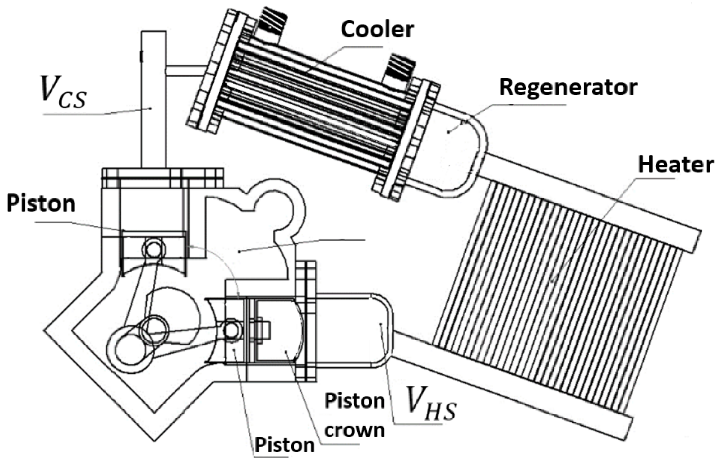
Figure 1. Stirling engine Alpha- type prototype.
Processes 14 00620 g001
Figure 2. Flowchart of the second-order numerical simulator in the MATLAB platform.
Processes 14 00620 g002
Figure 3. Graphical representation of the relationship between piston stroke, cylinder diameter, and efficiency. (a) 3D response surface showing efficiency as a function of piston stroke and cylinder diameter. (b) Top view of the response surface (normalized variable value), highlighting the optimal trend with a dashed yellow line.
Processes 14 00620 g003
Figure 4. Classification of system variable interactions based on slope (φ) values, defining categories A, B, C and D according to their influence.
Processes 14 00620 g004
Figure 5. Heatmap illustrating the interactions among variables, classified as strong (A), significant (B), weak (C), and null (D).
Processes 14 00620 g005
Figure 6. Hierarchy of system design variables interactions.
Processes 14 00620 g006
Figure 7. Flowchart of the guided exploration for system optimization.
Processes 14 00620 g007
Figure 8. Graphical representation of the combined effect of variables on system efficiency: (a) strong interaction, (b) null interaction.
Processes 14 00620 g008
Figure 9. Efficiency increases in each iteration.
Processes 14 00620 g009
Figure 10. Comparison of variable trends at design points: (a) Piston stroke, (b) Cylinder diameter, (c) Phase angle, and (d) Regenerator diameter.
Processes 14 00620 g010
Figure 11. Comparison of variable trends at design points: (a) Number of cooler tubes, (b) Length of cooler tubes, (c) Length of regenerator, and (d) Number of heater tubes.
Processes 14 00620 g011
Figure 12. Operational performance of the proposed designs in contrast to the initial design of the studied Stirling engine.
Processes 14 00620 g012
Table 1. Exploration ranges and design point of the variables.
EquipmentVariableDesign PointExploration Range
Min Increase Max
Units
E n g i n e P S 6.24.50.17.5 c m
D H C Y L 6.6 4.5 0.1 7.5 c m
A l p h 90301150 d e g r e e s
L P C 4.35930.17 c m
Heater L H T 16.612100.135 c m
D H T 0.30480.140.010.45 c m
N H T 3010150----
V H S 12.38912.3891120 c m 3
Regenerator L R 530.18 c m
D R 6.530.18 c m
M S H 6040180 w i r e s / c m
T H W 0.00410.00200.00010.0040 c m
Cooler L C T 21100.150 c m
D C T 0.21340.140.010.45 c m
N C T 85451120----
V C S 5.7855.7851120 c m 3
Table 2. Global scheme of system interactions.
Variable   n i 1216
1- φ d 1,2 φ d 1 , φ d 1,16
2 φ d 2,1 - φ d 2 , φ d 2,16
φ d , 1 φ d , 2 - φ d , 16
16 φ d 16,1 φ d 16,2 φ d 16 , -
Φ n i Φ 1 Φ 2 Φ Φ 16
Table 3. Comparison of the initial design and the optimized design points obtained using the G.U.I.O. and G.I.P.O. methodologies.
VariableInitialDesign 1Design 2Units
Efficiency36.239.7340.75%
Power2393.72628.82658.6W
P S 6.26.47.5 cm
D HCYL 6.66.45.8 cm
Alph 905850 d e g r e e s
L P C 4.35977 c m
L H T 16.61221.420.3 c m
D H T 0.30480.30.27 c m
N H T 302222----
V H S 12.38912.38912.389 c m 3
L R 56.47 c m
D R 6.55.44.1 c m
M S H 605752 w i r e s / c m
T H W 0.00410.00590.006 c m
L C T 2121.125 c m
D C T 0.21340.190.21 c m
N C T 8510685----
V C S 5.7855.7855.785 c m 3
Disclaimer/Publisher’s Note: The statements, opinions and data contained in all publications are solely those of the individual author(s) and contributor(s) and not of MDPI and/or the editor(s). MDPI and/or the editor(s) disclaim responsibility for any injury to people or property resulting from any ideas, methods, instructions or products referred to in the content.