Abstract
This study explores the effects of electrically assisted turbochargers (EAT) on the performance of diesel engines by incorporating an electrical motor/generator into a conventional turbocharged model. The engine simulations were conducted at three different power levels of 2, 2.5, and 3 kW to assess the impact of electrical assistance. The results demonstrated that EAT significantly boosts engine performance, with an increase in boost pressure of up to 58.9% at 1000 rpm and an average increase of 30.9% across the low engine speed range (1000–2200 rpm). Additionally, the maximum turbocharger speed was achieved at lower engine speeds, dropping from 2400 rpm to as low as 1600 rpm with 3 kW assistance. Engine torque improved by up to 28.2% at 1000 rpm, and brake-specific fuel consumption (BSFC) was reduced by as much as 8.1%. Transient simulations showed notable improvements in response times, with turbo lag reduced by up to 53% under acceleration conditions. Overall, EAT technology provides significant enhancements in engine efficiency, torque output, fuel economy, and transient response, positioning it as a promising solution for improving diesel engine performance, particularly in addressing turbo lag and low-speed inefficiencies.
1. Introduction
With the increasing stringency of global emission regulations and fuel economy requirements, automotive companies are accelerating their research, development, and introduction of new technologies to provide compliant solutions [1,2,3]. Electrically assisted turbocharging (EAT) is one of them and is an innovative technology developed to enhance the efficiency and performance of internal combustion engines (ICEs) and to reduce harmful emissions [4,5,6,7]. Traditional turbocharging systems rely on the kinetic energy of exhaust gases to compress the intake air, thereby allowing a higher amount of air–fuel mixture to enter the combustion chamber, increasing engine power [8,9]. However, at low engine speeds, the turbo may not generate sufficient pressure, leading to a performance issue known as turbo lag [10]. EAT addresses this challenge by employing electric motors to support the turbo independently of exhaust gases, enabling immediate response and allowing the engine to operate efficiently across a wider range of speeds [11,12].
One of the key advantages of this technology is its ability to maintain high efficiency at all engine speeds. EAT improves low-end performance while also optimizing fuel economy and reducing emissions [13,14,15,16,17]. As a result, it offers superior performance and promotes lower fuel consumption and environmentally friendly driving in vehicles [18,19,20]. This technology plays a pivotal role in helping the automotive industry meet its efficiency and sustainability goals through electric and hybrid solutions [21,22,23]. EAT systems present an innovative alternative to traditional boosting methods for enhancing the efficiency of internal combustion engines, and the boosting of ICEs has long been a compelling area of research and remains relevant today [24,25,26,27,28]. This interest is likely to persist in the coming years due to ongoing emission regulations, trends toward engine downsizing, and the need for improved fuel efficiency [29,30,31,32,33].
Katrašnik et al. [34] indicated that the dynamic response of turbocharged diesel engines can be enhanced through electric assisting systems, which can either provide direct energy via an integrated starter–generator–booster (ISG) mounted on the engine flywheel or supply energy indirectly through an electrically assisted turbocharger. The results demonstrate that electrically assisted systems significantly improve load acceptance in turbocharged engines. Furthermore, these systems allow for reductions in production and operating costs by enabling the downsizing of electrically assisted engines while maintaining performance. An electrically assisted turbocharger facilitates a rapid increase in engine power due to its substantial boost pressure increase. To efficiently enhance the dynamics of turbocharged engines, an electric motor (EM) with a much higher angular acceleration than that of the conventional turbocharger is necessary, a requirement applicable to all types of turbochargers, including free-floating, waste-gated, and variable-nozzle turbine (VNT) configurations. Panting et al. [35] highlighted that using a direct-drive motor generator to add or subtract power from the turbocharger shaft provides an additional degree of freedom for better engine–turbocharger matching. This method, known as hybrid turbocharging, can significantly enhance both engine efficiency and transient response. The study presents theoretical findings on the advantages of hybrid turbocharging over conventional systems in both steady-state and transient operations. Four different turbocharger configurations were analyzed alongside the baseline engine, demonstrating that re-matching turbocharger components improves design point cycle efficiency and enhances full-throttle transient performance while also reducing fuel consumption during steady-state operation. Tavčar et al. [36] conducted a comprehensive analysis comparing various electrically assisted turbocharger configurations with a baseline turbocharged high-speed direct-injection (HSDI) diesel engine. The study evaluated systems including an electrically assisted turbocharger, a turbocharger with an additional electric compressor, and an electrically split turbocharger using a validated engine and vehicle model. Results across various driving conditions, such as tip-in scenarios and the New European Driving Cycle (NEDC), demonstrated that electrically assisted turbocharging improves transient engine response and drive ability. Additionally, these systems enhance steady-state torque output through energy stored in electric devices. Notably, the electrically split turbocharger significantly reduces fuel consumption in urban driving, while the turbocharger with an additional electric compressor delivers the highest low-speed torque and fastest transient response. Terdich et al. [37] assessed the improvements in engine energy efficiency and transient response correlated to the hybridization of the air system. To achieve this, an electrically assisted turbocharger with a variable-geometry turbine was compared to a similar, not hybridized system over step changes in engine load. The variable-geometry turbine was controlled to provide different levels of initial boost, including one optimized for efficiency, and to change its flow capacity during the transient. The engine modeled was a 7 L, six-cylinder diesel engine with a power output of over 200 kW and a sub-10 kW turbocharger electric assistance power. To improve the accuracy of the model, the turbocharger turbine was experimentally characterized by means of a unique testing facility available at Imperial College, and the data were extrapolated by means of a turbine meanline model. Optimization of the engine boost to minimize pumping losses showed a reduction in brake-specific fuel consumption (BSFC) by up to 4.2%. Kolmanovsky and Stefanopoulou [38] simulated a bi-directional energy transfer system between the turbocharger shaft and energy storage on a medium-sized passenger car. The primary goal was not to maximize electric energy recovery for fuel consumption improvement; instead, the EAT system aimed to regenerate its own power during full-load accelerations to optimize transient response. Maximum power output in both motoring and generating modes was limited to 1.5 kW, with assumed efficiencies of 90% for the motor and 70% for the generator. Using optimal control techniques, they defined the best transient operating strategy, reporting a 10% improvement in takeoff performance during 0–40 km/h acceleration in first gear, without compromising smoke emissions and maintaining comparable fuel consumption to conventional turbocharged engines. Additionally, they concluded that to offset the acceleration improvement achieved, the rotor’s moment of inertia would need to increase by 250%. In extending their research to parallel hybrid configurations with an electric motor on the drive shaft, Kolmanovsky and Stefanopoulou [39] found that the hybrid vehicle required 10.3 kW to achieve the same acceleration time as the 1.5 kW EAT system, while Shahed [40] indicated that his drive-line motor assist system needed 10 kW to match the performance of a 2 kW EAT system. Both studies noted similar fuel consumption across both system types when accounting for electric production. This power difference is attributed to the hybrid vehicle directly delivering electric torque to the crankshaft, whereas the EAT system increases air supply, enabling more fuel combustion to generate additional torque. Consequently, assisted turbocharging technology presents significant potential to deliver similar benefits—fuel efficiency and transient response—compared to hybrid systems, without the added weight and cost [41]. Men et al. [42] investigated the performance of an electrically assisted boosting (eBoost) system integrated into a diesel engine under both steady-state and transient conditions. The results showed that the eBoost configuration significantly improved fuel efficiency at moderate engine speeds and significantly increased maximum torque at low speeds. Furthermore, the system was shown to improve transient response by reducing turbo lag by up to 60%. In a previous study conducted by Ozgur and Aydin [43], the effect of an EAT on the performance characteristics of a diesel engine was investigated using one-dimensional simulations using the AVL Boost software. Two engine models—a conventional turbocharger and an electrically assisted turbocharger—were compared to evaluate torque, power output, and specific fuel consumption. The results revealed that the EAT system significantly increased low-speed torque by up to 30% and reduced specific fuel consumption by approximately 27% at low engine speeds and 9% at higher engine speeds.
The objective of this study is to investigate the effects of an electrically assisted turbocharger on diesel engine performance parameters. The experimental work of matching an electrically assisted turbocharger to an engine is rather expensive; therefore, a conventional turbocharged automotive diesel engine was simulated using AVL Boost, and the simulation results were compared with experimental results. Engine model simulation was run at three different electrical powers of 2, 2.5, and 3 kW, respectively, with the purpose of investigating the effect of electrical power assistance on the turbocharger. Boost pressure, turbocharger speed, turbine inlet temperature, turbine outlet temperature, turbine inlet pressure, electric power, electric motor mechanical work, engine torque, engine power, and BSFC values were simulated for the three electric power values and interpreted. Also, the transient behavior of the electrically assisted turbocharger was simulated and commented on.
Although several studies have investigated EAT technologies, most have focused on either theoretical aspects or limited performance cases. Few works have provided a systematic, comparative assessment of different electrical assistance levels on diesel engine performance across both steady-state and transient operating conditions. This study contributes a novel simulation-based evaluation of EAT’s impacts on engine response, particularly in mitigating turbo lag and improving low-speed torque. The research is distinguished by its inclusion of three discrete electric assist power levels (2, 2.5, and 3 kW) and evaluation under full-load transient events. Furthermore, the study leverages AVL Boost simulation with experimentally validated models, enhancing the reliability and reproducibility of findings. This work extends prior efforts by providing detailed performance metrics under dynamic conditions and establishing scalable design implications for modern diesel engines.
Unlike previous studies that mainly address steady-state operation or assume idealized motor–turbo coupling, this work evaluates dynamic, power-scaled electric assist levels under transient conditions, providing practical insights for engine design and ECU calibration.
2. Materials and Methods
The experimental data for the diesel engine used in the modeling were obtained from Ceausu’s doctoral thesis [44], and the electrically assisted turbocharger was modeled using these experimental data. The engine has a total displacement of 2499 cm3 and four valves per cylinder. Engine specifications are listed in Table 1. The boost pressure is limited by a spring-loaded wastegate. Specifications of the turbocharger are given in Table 2.

Table 1.
Specifications of the experimental engine [44].
Table 2.
Specifications of the RFC5 series turbocharger [44].
The electrically assisted turbocharged automotive diesel engine, which is shown in Figure 1, was modeled by using the Boost tool of AVL Advanced Simulation Technologies. The electrical device, which can work in both motor and generator mode, was mechanically connected to the turbocharger for power assistance. An electronic control unit was used to control electrical devices in the model.
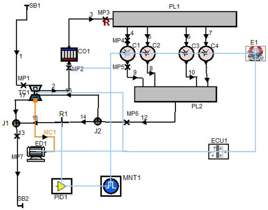
Figure 1.
Schematic model view of the electrically assisted turbocharged diesel engine as simulated in AVL Boost.
The electric motor was modeled as a dynamic component with 90% efficiency (motoring) and 70% (generating) with instantaneous torque response to simulate ideal dynamic behavior controlled by an ECU module. The electric motor was dynamically coupled to the turbocharger shaft and controlled via an ECU to simulate real-time assist behavior under varying engine loads and speeds. Engine operating conditions were simulated across the 1000–4000 rpm range at full load, and transient cases were modeled using 50–200 Nm load steps.
The simulation is based on 1D gas dynamics using conservation equations for mass, momentum, and energy. Engine torque T is computed via , where Vd is displacement volume. Compressor and turbine performance are interpolated from manufacturer maps, while the electric motor torque Te(t) is applied as a function of boost demand through ECU logic.
The one-dimensional engine model was developed in AVL Boost by solving the unsteady conservation equations for mass, momentum, and energy in each control volume. The finite volume method was applied to discretize the governing equations:
Mass conservation:
Momentum conservation:
Energy conservation:
Here, ρ is density, u is flow velocity, p is pressure, τ is shear stress, et is total specific energy, Q˙ is heat addition, and Sm and Se are source terms due to mass or energy addition.
The in-cylinder process was modeled using the Vibe combustion law to represent the heat release rate:
where xb is the mass fraction burned, a and m are shape parameters, θ0 is the start of combustion, and Δθ is the combustion duration.
The instantaneous heat transfer between the gas and cylinder walls was calculated using the Woschni correlation:
where h is the heat transfer coefficient, B is bore, p is cylinder pressure, T is gas temperature, and w is characteristic gas velocity.
The intake and exhaust systems, including plenums, pipes, and junctions, were modeled as 1D ducts governed by the same conservation equations. Friction losses were calculated using the Darcy–Weisbach equation:
where f is the Fanning friction factor, L is pipe length, and D is diameter.
The turbocharger performance was modeled using manufacturer-supplied compressor and turbine maps. The compressor mass flow rate was interpolated from the map as a function of pressure ratio and corrected speed:
The turbine power was determined from the enthalpy drop across the turbine:
Mechanical losses in the bearing system were accounted for by a friction torque model.
The electric motor/generator was coupled to the turbocharger shaft via a mechanical connection. The motor torque was modeled as:
where Pem is the electrical power (positive in assist mode, negative in generation mode) and ωtc is the turbocharger shaft speed.
The control strategy for the electrically assisted turbocharger aimed to supply additional torque during transient acceleration or low-speed operation to reduce turbo lag.
The simulation model was validated using experimental data reported by Ceausu [44], including torque and BSFC values, and adjusted to match real engine behavior with high fidelity.
AVL Boost applies 1D fluid dynamics using the conservation of mass, energy, and momentum, along with heat transfer and combustion models. Compressor and turbine behavior was defined using map-based input, and the electric motor’s torque was regulated via a simulated ECU. The simulation was run under steady-state and transient boundary conditions across a range of speeds and loads.
An error analysis was performed by comparing simulation outputs with the experimental data from Ceausu [44]. The average absolute error remained within 5% for torque and BSFC across all tested conditions, validating the model’s accuracy.
Baseline simulation results (torque, BSFC) were compared with experimental measurements from Ceausu [44], and the deviation was within 5%, confirming the model’s predictive capability.
The engine model was calibrated by adjusting combustion and heat transfer parameters until simulated torque and BSFC matched Ceausu’s [44] experimental data within a ±5% error margin.
3. Results and Discussion
In this study, an electrical device acting as a motor/generator was integrated into the AVL Boost model in order to investigate the effects of an electrically assisted turbocharger on diesel engine performance parameters. The model simulation was run at three different electrical powers of 2, 2.5, and 3 kW at full-load conditions in order to investigate the effect of electrical power assistance on turbocharger. Boost pressure, turbocharger speed, turbine inlet temperature, turbine outlet temperature, turbine inlet pressure, electric power, electric motor mechanical work, engine torque, engine power, and BSFC values were simulated for three electric power values and compared with results of a conventional turbocharged automotive diesel engine.
The effects of different electrical power assistance levels on boost pressure values according to varying engine speeds at full-load conditions are presented in Figure 2. Boost pressure is limited to 2.3 bar with waste gate application. The maximum boost pressure, which is 2.3 bar, was obtained at 2400 rpm for the conventional turbocharged engine. When the turbocharger was assisted with 2, 2.5, and 3 kW electrical power, the maximum boost pressure was achieved at 2000, 1800, and 1600 rpm, respectively. The boost pressure of a conventional turbocharged diesel engine was increased with electrical power assistance. The boost pressure was increased by 41.2%, 50.2%, and 58.9% at 1000 rpm engine speed with 2, 2.5, and 3 kW electrical power assistance, respectively. The average increment is 22%, 27%, and 30.9% with an electrical power assistance of 2, 2.5, and 3 kW, respectively, for the low engine speed zone, which is between 1000–2200 rpm. Therefore, it can be concluded that providing electrical power assistance to the turbocharger enhances boost pressure in the turbo lag region where the exhaust gases are insufficient to provide proper boost pressure.
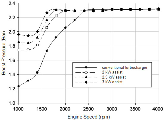
Figure 2.
Boost pressure versus engine speed for different electrical power assistance levels.
The variation in turbocharger speed according to varying engine speed values for different electrical power assistance values at full-load conditions is illustrated in Figure 3. It shows a similar trend to the boost pressure versus engine speed graph because the boost pressure is directly proportional to the turbocharger speed. The engine speed where the maximum turbocharger speed was obtained was reduced from 2400 rpm to 2000, 1800, and 1600 rpm with 2, 2.5, and 3 kW electrical power assistance, respectively. The turbocharger speed of the conventional turbocharged diesel engine was increased by 69.3%, 82%, and 92.6% at 1000 rpm, 48.6%, 58.2%, and 67% at 1200 rpm, and 35%, 43.1%, and 49.1% at 1400 rpm engine speed with 2, 2.5 and 3 kW electrical power assistance, respectively. The average increment is 28.7%, 34.4%, and 38.7% with electrical power assistance at 2, 2.5, and 3 kW, respectively, for the low engine speed zone, which is between 1000–2200 rpm.
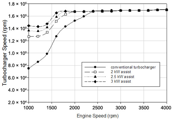
Figure 3.
Turbocharger speed versus engine speed for different electrical power assistance levels.
Figure 4 demonstrates the variation in the turbine inlet and outlet temperature values according to varying engine speeds for different electrical power assistance levels at full-load conditions. The turbine inlet and outlet temperature decreased with electrical power assistance.
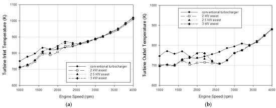
Figure 4.
Turbine (a) inlet and (b) outlet temperature versus engine speed at different engine loads.
The average reduction for the turbine inlet temperature was 4%, 2.5%, and 0.5% with 2, 2.5, and 3 kW electrical power assistance, respectively, for the low engine speed range (1000–2200 rpm). Furthermore, the average reduction for the turbine outlet temperature was 6.1%, 5%, and 3.6% with 2, 2.5, and 3 kW electrical power assistance, respectively, for the low engine speed range.
The variation in the turbine inlet pressure according to varying engine speed values for different electrical power assistance levels at full-load conditions is shown in Figure 5. The turbine inlet pressure of the conventional turbocharged diesel engine was increased with electrical power assistance. The turbine inlet pressure was increased by 16.6%, 20.8%, and 24.8% at 1000 rpm and 13%, 16.9%, and 20.7% at 1200 rpm engine speeds with 2, 2.5, and 3 kW electrical power assistance, respectively. The average increment is 7.8%, 9.2%, and 11.3% with electrical power assistance of 2, 2.5, and 3 kW, respectively.
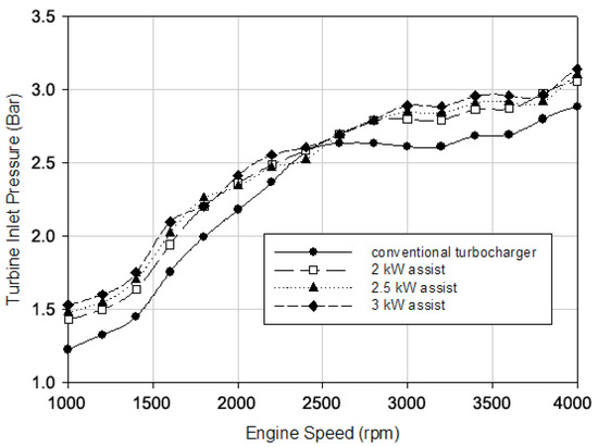
Figure 5.
Turbine inlet pressure versus engine speed for different electrical power assistance levels.
Figure 6 illustrates the variation in the electrical power and electric motor mechanical work values with respect to varying engine speeds for different electrical power assistance levels at full-load conditions. The electrical device acts as a motor and supplies electrical power until the target boost pressure is achieved, and when the target boost pressure is obtained, it acts as a generator and produces electrical power, as shown in the following figures. At low engine speeds, where the exhaust gas energy is insufficient to produce proper boost pressure, the turbocharger is electrically assisted and the boost pressure is increased, which improves the transient response of the turbocharger.
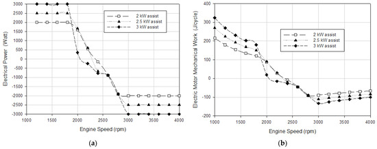
Figure 6.
(a) Electrical power and (b) electric motor mechanical work engine speed for different electrical power assistance levels.
The variation in engine torque according to varying engine speed values for different electrical power assistance levels at full-load conditions is presented in Figure 7. Engine torque was increased with electrical power assistance where the electric device acts as a motor in the low engine speed zone. The engine torque of the conventional turbocharged diesel engine was increased by 15.6%, 22%, and 28.2% at 1000 rpm, 12.1%, 18.1%, and 23.9% at 1200 rpm, and 9.4%, 17%, and 20.6% at 1400 rpm engine speeds with 2, 2.5 and 3 kW electrical power assistance, respectively. The average improvement is 8.8%, 15%, and 21.1% with electrical power assistance of 2, 2.5, and 3 kW, respectively, for the low engine speed zone, which is between 1000–2200. This effect was thought to be due mainly to the higher air–fuel ratio. It can be concluded that providing electrical power assistance to the conventional turbocharger improves low-end torque and reduces turbo lag during acceleration.
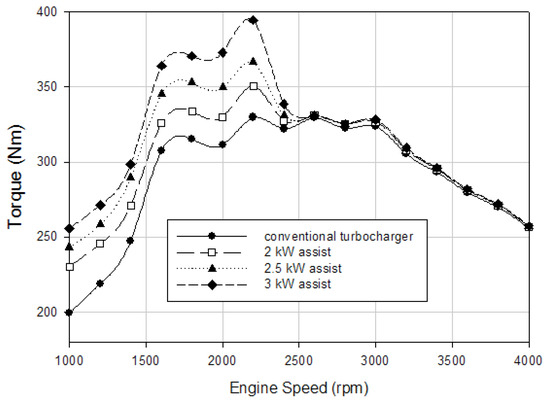
Figure 7.
Torque versus engine speed for different electrical power assistance levels.
The effects of different electrical power assistance levels on engine power values according to varying engine speeds at full-load conditions are presented in Figure 8. It demonstrates a similar trend to the engine torque versus engine speed graph because the engine power is directly proportional to the engine torque. Therefore, the same improvements were obtained for the engine power as the engine torque.
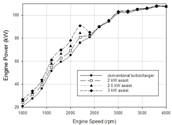
Figure 8.
Engine power versus low engine speed zone for different electrical power assistance levels.
Figure 9 indicates the variation in BSFC values according to varying engine speeds for different electrical power assistance levels at full-load conditions. BSFC was reduced with electrical power assistance where the electric device acts as a motor at the low engine speed zone. The BSFC of the conventional turbocharged diesel engine was improved by 6%, 8%, and 8.1% at 1000 rpm, 5.5%, 7%, and 8% at 1200 rpm, and 5%, 6%, and 7% at 1400 rpm engine speeds with 2, 2.5 and 3 kW electrical power assistance, respectively. The average improvement is 4.5%, 5.4%, and 6.1% with electrical power assistance of 2, 2.5, and 3 kW, respectively, for the low engine speed zone. It can be stated that providing electrical power assistance to the conventional turbocharger improves fuel efficiency during the low engine speed zone.
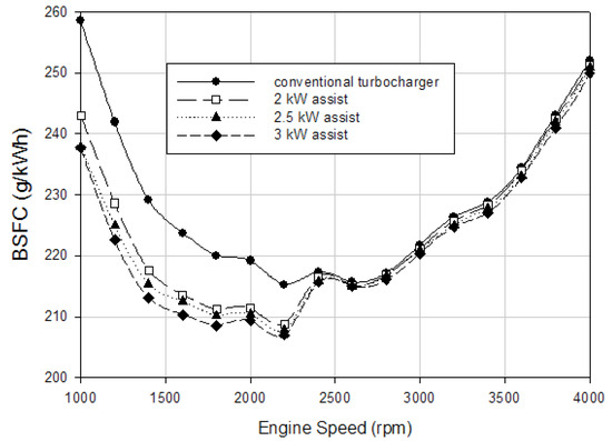
Figure 9.
BSFC versus engine speed for different electrical power assistance levels.
The load acceptance of the engine under transient operating conditions at a sudden load increase and under different turbocharger configurations is presented in Figure 10. The simulation introduces a 200 Nm sudden load application to the engine at 1500 rpm. Electric motors such as 2 kW, 2.5 kW, and 3 kW ensured a faster boost pressure rise and therefore allowed for larger quantities of the fuel to be injected into the cylinder. It is evident that the engine equipped with the electrically assisted turbocharger can accept a higher instant load. It can be stated that load acceptance of the engine was improved with electrical power assistance provided to the engine. Also, the conventional turbocharged engine could not respond to the load, so the engine speed decreased with respect to the increase in time. The electrically assisted turbocharger could accept the engine load; it took 3.75, 2.85, and 2.15 s for the engine to reach a 2000 rpm engine speed from 1500 rpm with 2, 2.5, and 3 kW electrical power assistance, respectively. Higher electrical power assistance resulted in a faster response to the load, which means a greater improvement in transient response.
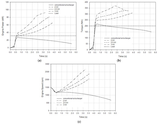
Figure 10.
Engine (a) power, (b) torque, and (c) speed versus time for 200 Nm engine load at 1500 rpm.
Figure 11 represents the variation in engine power and speed according to time for different electrical power assistance levels at an engine load under 100 Nm at a 1500 rpm engine speed. According to Figure 11, it took 3 s for the conventional turbocharged engine to produce 70 kW of engine power, and when the electrically assisted turbochargers were used, this time was reduced to 1.48, 1.27, and 1 s with 2, 2.5, and 3 kW electrical power assistance, respectively. The simulation results revealed that the engine load response time improved by 51%, 58%, and 67% with 2, 2.5, and 3 kW electrical power assistance, respectively. The conventional turbocharged engine attained 3000 rpm engine speed in 3.37 s under a 100 Nm load at a 1500 rpm initial engine speed. This time decreased to 2.43, 2.07, and 2.07 s with 2, 2.5, and 3 kW electrical power assistance, respectively. It can be stated that the transient response of the engine was improved by up to 40% with electrical power assistance.
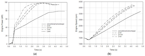
Figure 11.
Engine (a) power and (b) speed versus time for 100 Nm engine load at 1500 rpm.
Figure 12 compares the transient response of the turbocharger speed and the boost pressure under a 100 Nm load at a 1500 rpm engine speed for different turbocharger configurations. According to the figure, it took 3.18 s for the conventional turbocharger to reach a 170,000 rpm rotational speed, and by the time the electrically assisted turbochargers were used, this time was reduced to 1.66, 1.42, and 1.12 s with 2, 2.5, and 3 kW electrical power assistance, respectively. Figure 12 also shows that the time required for the turbocharger to produce 2.3 bar of boost pressure, which was 3.12 s for the conventional turbocharger, was reduced to 1.61, 1.37, and 1.07 s with the 2, 2.5, and 3 kW electrically assisted turbocharger. Since boost pressure is a function of turbocharger, speed similar trends were obtained. The effects of electrical power assistance are noticeable if the values during acceleration are examined: the turbocharger took 65% less time to reach 170,000 rpm, and the boost pressure took 66% less time to reach 2.3 bar with the 3 kW electrical power assistance.
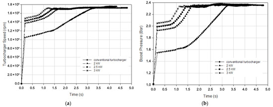
Figure 12.
(a) Turbocharger speed and (b) boost pressure versus time for 100 Nm engine load at 1500 rpm engine speed.
The effects of different levels of electrical power assistance on engine power output and speed over time under a 50 Nm load at 1000 rpm are illustrated in Figure 13. The data show that the conventional turbocharged engine required 2.68 s to reach 60 kW of power. In contrast, with the implementation of an electrically assisted turbocharger, the time decreased to 1.94 s with 2 kW of electrical power assistance, 1.74 s with 2.5 kW, and 1.50 s with 3 kW. The simulation results indicate that the engine load response time improved by 28%, 35%, and 44% with 2, 2.5, and 3 kW of electrical power assistance, respectively. Also, the conventional turbocharged engine achieved a speed of 2000 rpm in 2.25 s under a 50 Nm load at an initial speed of 1000 rpm. This time was reduced to 1.98 s with 2 kW of electrical power assistance, 1.87 s with 2.5 kW, and 1.73 s with 3 kW. This indicates an improvement in the transient response of the engine by 12%, 17%, and 23% with the corresponding levels of electrical power assistance.
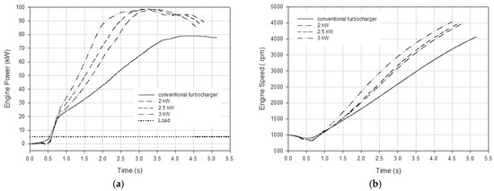
Figure 13.
Engine (a) power and (b) speed versus time for 50 Nm engine load at 1000 rpm.
Figure 14 compares the transient response of the turbocharger speed and the boost pressure under a 50 Nm load at a 1000 rpm engine speed for different turbocharger configurations. According to the figure, it took 3.47 s for the conventional turbocharger to reach 170,000 rpm, which is the maximum rotational speed, and when the electrically assisted turbocharger was used, this time was reduced to 2.36, 2.12, and 1.81 s with 2, 2.5, and 3 kW, respectively. The time required for the turbocharger to produce 2.3 bar, which is the peak boost pressure, which was 3.43 s for the conventional turbocharger, was reduced to 2.33, 2.08, and 1.78 s with the 2, 2.5, and 3 kW electrically assisted turbocharger. Since boost pressure is a function of turbocharger speed, similar trends were obtained. The simulation results indicated that the turbocharger response time was improved by 32%, 39%, and 48% with 2, 2.5, and 3 kW electrical power assistance, respectively.
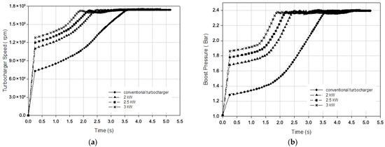
Figure 14.
(a) Turbocharger speed and (b) boost pressure versus time for 50 Nm engine load at 1000 rpm engine speed.
Figure 15 represents the variation in engine power and speed according to time for different electrical power assistance levels under a 100 Nm engine load at a 1000 rpm engine speed. According to the figure, it took 4.32 s for the conventional turbocharged engine to produce 60 kW of engine power, and when the electrically assisted turbocharger was used, this time was reduced to 2.90, 2.44, and 2.04 s with 2, 2.5, and 3 kW electrical power assistance, respectively. The simulation results revealed that the engine load response time improved by 33%, 44%, and 53% with 2, 2.5, and 3 kW electrical power assistance, respectively. Also, the conventional turbocharged engine reached a 2000 rpm engine speed in 3.63 s. This time decreased to 2.97, 2.61, and 2.32 s with 2, 2.5, and 3 kW electrical power assistance, respectively. It can be stated that the transient response of the engine was improved by 11%, 20%, and 36% with 2, 2.5, and 3 kW assistance, respectively.
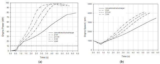
Figure 15.
Engine (a) power and (b) speed versus time for 100 Nm engine load at 1000 rpm engine speed.
Figure 16 compares the transient response of the turbocharger speed and the boost pressure under a 100 Nm load at a 1000 rpm engine speed for different turbocharger configurations. According to the figure, it took 5.19 s for the conventional turbocharger to reach 170,000 rpm, which is the maximum rotational speed, and when the electrically assisted turbocharger was used, this time was reduced to 3.37, 2.88, and 2.46 s with 2, 2.5, and 3 kW electrical power assistance, respectively. Also, the time required for the turbocharger to produce 2.3 bar, which is the peak boost pressure, which was 5.15 s for the conventional turbocharger, was reduced to 3.37, 2.88, and 2.46 s with 2, 2.5, and 3 kW assistance. Since boost pressure is a function of turbocharger speed, similar trends were obtained. The simulation results indicated that the turbocharger response time improved by 35%, 45%, and 53% with 2, 2.5, and 3 kW assistance, respectively.
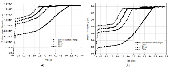
Figure 16.
(a) Turbocharger speed and (b) boost pressure versus time for 100 Nm engine load at 1000 rpm engine speed.
The effects of different electrical power assist levels on engine power and speed values according to time for vehicle acceleration from a 1000 rpm initial engine speed are presented in Figure 17. According to the figure, it took 1.46 s for the conventional turbocharged engine to produce 60 kW of engine power, and when the electrically assisted turbocharger was used, this time was reduced to 1.07, 1.01, and 0.95 s with 2, 2.5, and 3 kW electrical power assistance, respectively. The simulation results showed that the engine load response time improved by 27%, 31%, and 35% with 2, 2.5, and 3 kW assistance, respectively. Also, the conventional turbocharged engine reached a 2000 rpm engine speed in 1.25 s under vehicle acceleration from a 1000 rpm initial engine speed. This time was reduced to 1.09, 1.05, and 1.03 s with 2, 2.5, and 3 kW electrical power assistance, respectively. It can be stated that the transient response of the engine was improved by 13%, 16%, and 18% with 2, 2.5, and 3 kW assistance, respectively.
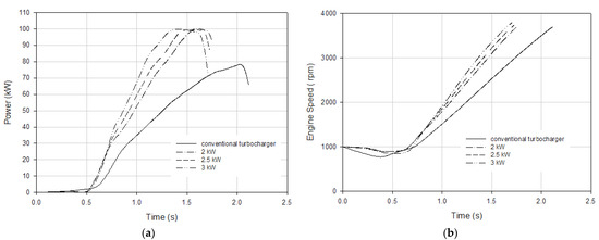
Figure 17.
Engine (a) power and (b) speed versus time for vehicle acceleration from 1000 rpm engine speed.
Figure 18 compares the transient response of the turbocharger speed and the boost pressure under vehicle acceleration from a 1000 rpm initial engine speed for different turbocharger configurations. According to the figure, it took 1.84 s for the conventional turbocharger to reach 170,000 rpm, which is the maximum rotational speed, and when the electrically assisted turbocharger was used, this time was reduced to 1.32, 1.22, and 1.14 s with 2, 2.5, and 3 kW electrical power assistance, respectively. The figure also shows that the time required for the turbocharger to produce 2.3 bar, which is the peak boost pressure, which was 1.87 s for the conventional turbocharger, was reduced to 1.31, 1.21, and 1.15 s with 2, 2.5, and 3 kW assistance, respectively. Since boost pressure is a function of turbocharger speed, similar trends were obtained. The simulation results indicated that the turbocharger response time was improved by 30%, 35%, and 39% with 2, 2.5, and 3 kW assistance, respectively.
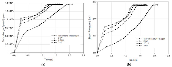
Figure 18.
(a) Turbocharger speed and (b) boost pressure versus time for vehicle acceleration from 1000 rpm engine speed.
The boost pressure increase at lower engine speeds is primarily attributed to the immediate torque delivery of the electric motor, which compensates for the traditional exhaust energy delay in spooling up the turbocharger. This early boost activation improves the air–fuel ratio available for combustion, directly enhancing the torque and reducing BSFC. For instance, 3 kW electrical assistance raised the boost pressure by 58.9% at 1000 rpm, translating to an approximate 28% increase in engine torque—effects that cannot be achieved via conventional turbochargers alone at such low speeds.
The turbocharger speed increases in parallel with the boost pressure, confirming the direct influence of electric motor support on compressor dynamics. The engine reaches the maximum turbocharger speed 800 rpm earlier with 3 kW assistance, reducing the delay in torque buildup and improving drivability under load. These dynamics are particularly beneficial in urban and off-road applications, where frequent accelerations from low rpm are common.
Furthermore, the reduction in the turbine inlet and outlet temperatures with electrical assistance highlights a thermodynamic benefit of a lower exhaust backpressure and optimized combustion. This may also positively influence engine durability and emissions control.
Compared to VGTs and mild hybrid systems, the EAT approach demonstrated comparable or superior transient performance improvements at lower power and system complexity levels, consistent with prior studies [37,39].
Comparison with the works of Kolmanovsky and Stefanopoulou [38,39], as well as Tavčar et al. [36], confirms the consistency of the findings but also emphasizes the expanded scope of this study, which uniquely considers power-matched assistance levels and practical load simulations. These features strengthen the applicability of EAT systems to production-level engine control strategies.
Compared to our earlier work [43], which examined only steady-state behavior, this study extends the analysis to transient conditions, incorporates scalable electric assistance levels, and dynamically models motor–turbocharger interactions, offering more practical insights for engine control strategies.
Unlike conventional methods that treat electrical assistance as a static input, this study dynamically models motor–turbocharger interactions and evaluates transient performance under realistic load conditions, enabling more accurate and practical insights.
The configuration with 3 kW electrical assistance at low engine speeds (1000–1600 rpm) was found to be the most effective in improving torque, fuel efficiency, and transient response, making it the optimal setup for the analyzed engine.
Although the simulation provides valuable insights, it has several limitations. Real-world actuator delays, thermal effects, and part-load variability were not fully modeled. Additionally, the ECU logic was simplified, and long-term durability factors were beyond the current scope.
4. Conclusions
In this study, an electrical device acting as a motor/generator was integrated into a conventional model in order to investigate the effects of an electrically assisted turbocharger on diesel engine performance parameters. The engine model simulation was run at three different electrical powers of 2, 2.5, and 3 kW, respectively. Also, the transient behavior of the EAT was simulated and examined. The following conclusions were obtained:
- The boost pressure of the conventional turbocharged diesel engine was increased with electrical power assistance. The boost pressure was increased by 41.2%, 50.2%, and 58.9% at a 1000 rpm engine speed with 2, 2.5, and 3 kW electrical power assistance, respectively. The average increment was 22%, 27%, and 30.9% with electrical power assistance of 2, 2.5, and 3 kW, respectively, for the low engine speed zone, which is between 1000–2200 rpm.
- The results revealed that the engine speed where the maximum turbocharger speed was obtained was reduced from 2400 rpm to 2000, 1800, and 1600 rpm with 2, 2.5, and 3 kW electrical power assistance, respectively.
- According to the engine simulation results, the engine torque of the conventional turbocharged diesel engine was increased by 15.6%, 22%, and 28.2% at 1000 rpm, 12.1%, 18.1%, and 23.9% at 1200 rpm, and 9.4%, 17%, and 20.6% at 1400 rpm engine speeds with 2, 2.5, and 3 kW electrical power assistance, respectively.
- The BSFC of the conventional turbocharged diesel engine was improved by 6%, 8%, and 8.1% at 1000 rpm, 5.5%, 7%, and 8% at 1200 rpm, and 5%, 6%, and 7% at 1400 rpm engine speeds with 2, 2.5, and 3 kW electrical power assistance, respectively.
- The transient simulation results revealed that the transient response of the conventional turbocharger improved up to 35%, 45%, and 53% with 2, 2.5, and 3 kW electrical power assistance, respectively, under different load conditions. It can be stated that the turbo lag time of the conventional turbocharger can be reduced by 53% during acceleration with 3 kW electrical power assistance.
Author Contributions
Conceptualization, T.O. and K.A.; methodology, T.O.; investigation, T.O.; writing—original draft preparation, T.O.; writing—review and editing, T.O. and K.A.; visualization, T.O.; supervision, K.A. All authors have read and agreed to the published version of the manuscript.
Funding
This research received no external funding.
Data Availability Statement
The raw data supporting the conclusions of this article will be made available by the authors on request.
Acknowledgments
The authors thank the AVL Company, Austria for providing the AVL Boost software.
Conflicts of Interest
The authors declare no conflicts of interest.
Abbreviations
The following abbreviations are used in this manuscript:
| EAT | Electrically assisted turbocharging |
| ICE | Internal combustion engine |
| BSFC | Brake-specific fuel consumption |
| ISG | Integrated starter–generator–booster |
| EM | Electric motor |
| VNT | Variable-nozzle turbine |
| HSDI | High-speed direct-injection |
| NEDC | The new European driving cycle |
References
- Gerada, D.; Huang, X.; Zhang, C.; Zhang, H.; Zhang, X.; Gerada, C. Electrical Machines for Automotive Electrically Assisted Turbocharging. IEEE/ASME Trans. Mechatron. 2018, 23, 2054–2065. [Google Scholar] [CrossRef]
- Galindo, J.; Climent, H.; Varnier, O.; Patil, C. Effect of Boosting System Architecture and Thermomechanical Limits on Diesel Engine Performance: Part II—Transient Operation. Int. J. Engine Res. 2018, 19, 873–885. [Google Scholar] [CrossRef]
- Grill, M.; Keller, P.; Mohon, S.; van Maanen, K.; Wenzel, W.; Liu, X.; Negandhi, V. Development of a 48V P0 Demonstration Vehicle with EBooster® Air Charging. In 18. Internationales Stuttgarter Symposium; Springer: Wiesbaden, Germany, 2018; pp. 551–566. [Google Scholar]
- Katsanos, C.O.; Hountalas, D.T.; Zannis, T.C. Simulation of a Heavy-Duty Diesel Engine with Electrical Turbocompounding System Using Operating Charts for Turbocharger Components and Power Turbine. Energy Convers. Manag. 2013, 76, 712–724. [Google Scholar] [CrossRef]
- Millo, F.; Mallamo, F.; Pautasso, E.; Ganio Mego, G. The Potential of Electric Exhaust Gas Turbocharging for HD Diesel Engines. In Proceedings of the SAE 2006 World Congress & Exhibition, Sacramento, CA, USA, 9–12 July 2006. [Google Scholar]
- Newman, P.; Luard, N.; Jarvis, S.; Richardson, S.; Smith, T.; Jackson, R.; Rochette, C.; Lee, D.; Criddle, M. Electrical Supercharging for Future Diesel Powertrain Applications. In Proceedings of the 11th International Conference on Turbochargers and Turbocharging, London, UK, 13–14 May 2014; Elsevier: Amsterdam, The Netherlands, 2014; pp. 207–216. [Google Scholar]
- Kong, X.; Guo, H.; Cheng, Z.; Men, R. Dynamic Characteristics of Electrically Assisted Turbocharger Rotor System Under Strong Impacts. J. Vib. Eng. Technol. 2024, 12, 7955–7967. [Google Scholar] [CrossRef]
- Filipi, Z.; Wang, Y.; Assanis, D.N. Effect of Variable Geometry Turbine (VGT) on Diesel Engine and Vehicle System Transient Response. In Proceedings of the SAE 2001 World Congress, Detroit, MI, USA, 5–8 March 2001. [Google Scholar]
- Dambrosio, L.; Pascazio, G.; Fortunato, B. Vgt Turbocharger Controlled by an Adaptive Technique. IEEE/ASME Trans. Mechatron. 2003, 8, 492–499. [Google Scholar] [CrossRef]
- Duan, B.; Yang, C.; Wang, Y.; Wang, H.; Wang, B.; Deng, H.; Wang, B. Model-Based Performance Study of Electrically Assisted Turbocharging Diesel Engine. J. Phys. Conf. Ser. 2023, 2437, 012016. [Google Scholar] [CrossRef]
- Ricardo, M.-B.; Apostolos, P.; Yang, M. Overview of Boosting Options for Future Downsized Engines. Sci. China Technol. Sci. 2011, 54, 318–331. [Google Scholar] [CrossRef]
- Lee, W.; Schubert, E.; Li, Y.; Li, S.; Bobba, D.; Sarlioglu, B. Overview of Electric Turbocharger and Supercharger for Downsized Internal Combustion Engines. IEEE Trans. Transp. Electrif. 2017, 3, 36–47. [Google Scholar] [CrossRef]
- Winterbone, D.E.; Benson, R.S.; Mortimer, A.G.; Kenyon, P.; Stotter, A. Transient Response of Turbocharged Diesel Engines. In Proceedings of the 1977 International Automotive Engineering Congress and Exposition, Detroit, MI, USA, 28 February–4 March 1977. [Google Scholar]
- Grönman, A.; Sallinen, P.; Honkatukia, J.; Backman, J.; Uusitalo, A. Design and Experiments of Two-Stage Intercooled Electrically Assisted Turbocharger. Energy Convers. Manag. 2016, 111, 115–124. [Google Scholar] [CrossRef]
- Yang, M.Y.; Martinez-Botas, R.F.; Zhuge, W.L.; Qureshi, U.; Richards, B. Centrifugal Compressor Design for Electrically Assisted Boost. IOP Conf. Ser. Mater. Sci. Eng. 2013, 52, 042014. [Google Scholar] [CrossRef]
- Pesiridis, A.; Saccomanno, A.; Tuccillo, R.; Capobianco, A. Conceptual Design of a Variable Geometry, Axial Flow Turbocharger Turbine. In Proceedings of the 13th International Conference on Engines & Vehicles, Capri, Italy, 10–14 September 2017. [Google Scholar]
- Pesiridis, A.; Ferrara, A.; Tuccillo, R.; Chen, H. Conceptual Design of an Axial Turbocharger Turbine. In Proceedings of the ASME Turbo Expo 2017: Turbomachinery Technical Conference and Exposition, Volume 8: Microturbines, Turbochargers and Small Turbomachines; Steam Turbines, Charlotte, NC, USA, 26–30 June 2017; American Society of Mechanical Engineers: Washington, DC, USA, 2017. [Google Scholar]
- Dimitriou, P.; Burke, R.; Zhang, Q.; Copeland, C.; Stoffels, H. Electric Turbocharging for Energy Regeneration and Increased Efficiency at Real Driving Conditions. Appl. Sci. 2017, 7, 350. [Google Scholar] [CrossRef]
- Lee, W.; Schubert, E.; Li, Y.; Li, S.; Bobba, D.; Sarlioglu, B. Electrification of Turbocharger and Supercharger for Downsized Internal Combustion Engines and Hybrid Electric Vehicles-Benefits and Challenges. In Proceedings of the 2016 IEEE Transportation Electrification Conference and Expo (ITEC), Dearborn, MI, USA, 27–29 June 2016; pp. 1–6. [Google Scholar]
- Noguchi, T.; Takata, Y.; Pyamashita, Y.; Komatsu, Y.; Ibaraki, S. 220,000-r/Min, 2-kW PM Motor Drive for Turbocharger. Electr. Eng. Jpn. 2007, 161, 31–40. [Google Scholar] [CrossRef]
- Ishikawa, N. A Study on Emissions Improvement of a Diesel Engine Equipped with a Mechanical Supercharger. Int. J. Engine Res. 2012, 13, 99–107. [Google Scholar] [CrossRef]
- Tae-Woo, L.; Do-Kwan, H. Performance Validation of High-Speed Motor for Electric Turbochargers Using Various Test Methods. Electronics 2023, 12, 2937. [Google Scholar] [CrossRef]
- Subramaniam, K.; Salim, W.S.I.W. Modelling an Electrically Turbocharged Engine and Predicting the Performance Under Steady-State Engine. Int. J. Automot. Mech. Eng. 2021, 18, 9244–9252. [Google Scholar] [CrossRef]
- Wu, C.; Kang, S.; Li, S.; Xie, H. Impact of Electrically Assisted Turbocharger on the Intake Oxygen Concentration and Its Disturbance Rejection Control for a Heavy-Duty Diesel Engine. Energies 2019, 12, 3014. [Google Scholar] [CrossRef]
- Alshammari, M.; Xypolitas, N.; Pesyridis, A. Modelling of Electrically-Assisted Turbocharger Compressor Performance. Energies 2019, 12, 975. [Google Scholar] [CrossRef]
- Alshammari, M.; Alshammari, F.; Pesyridis, A. Electric Boosting and Energy Recovery Systems for Engine Downsizing. Energies 2019, 12, 4636. [Google Scholar] [CrossRef]
- Hu, S.; Yu, F.; Cheng, Z.-Y.; Wang, Y.; Shen, J.-X. Study on High-Speed Permanent Magnet Synchronous Motor with Large Airgap for Electrically Assisted Turbocharger. In Proceedings of the 2021 24th International Conference on Electrical Machines and Systems (ICEMS), Gyeongju, Republic of Korea, 31 October–3 November 2021; pp. 365–370. [Google Scholar]
- Song, K.; Upadhyay, D.; Xie, H. An Assessment of the Impacts of Low-Pressure Exhaust Gas Recirculation on the Air Path of a Diesel Engine Equipped with Electrically Assisted Turbochargers. Int. J. Engine Res. 2021, 22, 3–21. [Google Scholar] [CrossRef]
- Rose, A.T.J.M.; Akehurst, S.; Brace, C.J. Modelling the Performance of a Continuously Variable Supercharger Drive System. Proc. Inst. Mech. Eng. Part D J. Automob. Eng. 2011, 225, 1399–1414. [Google Scholar] [CrossRef]
- Kesgin, U. Effect of Turbocharging System on the Performance of a Natural Gas Engine. Energy Convers. Manag. 2005, 46, 11–32. [Google Scholar] [CrossRef]
- Gharehghani, A.; Koochak, M.; Mirsalim, M.; Yusaf, T. Experimental Investigation of Thermal Balance of a Turbocharged SI Engine Operating on Natural Gas. Appl. Therm. Eng. 2013, 60, 200–207. [Google Scholar] [CrossRef]
- Mazanec, J.M.; Vang, N.S.; Kokjohn, S.L. Enabling Off-Highway Diesel Engine Downsizing and Performance Improvement Using Electrically Assisted Turbocharging. Int. J. Engine Res. 2023, 24, 4104–4126. [Google Scholar] [CrossRef]
- van Zuijlen, R.; Kupper, F.; Willems, F. Energy Management for RCCI Engines with Electrically-Assisted Turbocharging. IFAC-PapersOnLine 2022, 55, 354–359. [Google Scholar] [CrossRef]
- Katrašnik, T.; Medica, V.; Trenc, F. Analysis of the Dynamic Response Improvement of a Turbocharged Diesel Engine Driven Alternating Current Generating Set. Energy Convers. Manag. 2005, 46, 2838–2855. [Google Scholar] [CrossRef]
- Panting, J.; Pullen, K.R.; Martinez-Botas, R.F. Turbocharger Motor-Generator for Improvement of Transient Performance in an Internal Combustion Engine. Proc. Inst. Mech. Eng. Part D J. Automob. Eng. 2001, 215, 369–383. [Google Scholar] [CrossRef]
- Tavčar, G.; Bizjan, F.; Katrašnik, T. Methods for Improving Transient Response of Diesel Engines—Influences of Different Electrically Assisted Turbocharging Topologies. Proc. Inst. Mech. Eng. Part D J. Automob. Eng. 2011, 225, 1167–1185. [Google Scholar] [CrossRef]
- Terdich, N.; Martinez-Botas, R.F.; Romagnoli, A.; Pesiridis, A. Mild Hybridization via Electrification of the Air System: Electrically Assisted and Variable Geometry Turbocharging Impact on an off-Road Diesel Engine. J. Eng. Gas Turbine Power 2014, 136, 031703. [Google Scholar] [CrossRef]
- Kolmanovsky, I.V.; Stefanopoulou, A.G. Optimal Control Techniques for Assessing Feasibility and Defining Subsystem Level Requirements: An Automotive Case Study. IEEE Trans. Control Syst. Technol. 2001, 9, 524–534. [Google Scholar] [CrossRef]
- Kolmanovsky, I.; Stefanopoulou, A.G. Evaluation of Turbocharger Power Assist System Using Optimal Control Techniques. In Proceedings of the SAE 2000 World Congress, Las Vegas, NV, USA, 24–28 July 2000. [Google Scholar] [CrossRef]
- Shahed, S.M. An Analysis of Assisted Turbocharging with Light Hybrid Powertrain. In Proceedings of the SAE 2000 World Congress, Detroit, MI, USA, 6–9 March 2000. [Google Scholar] [CrossRef]
- Varnier, O. Trends and Limits of Two-Stage Boosting Systems for Automotive Diesel Engines. Ph.D. Thesis, Universitat Politècnica de València, València, Spain, 2012. [Google Scholar]
- Men, Y.; Martz, J.B.; Curtis, E.; Zhu, G.G. A Numerical Study of an Electrically Assisted Boosting System for Turbocharged Diesel Engines. In Proceedings of the ASME 2019 Dynamic Systems and Control Conference, Volume 2: Modeling and Control of Engine and Aftertreatment Systems; Modeling and Control of IC Engines and Aftertreatment Systems; Modeling and Validation; Motion Planning and Tracking Control; Multi-Agent and Networked Systems, Park City, UT, USA, 8–11 October 2019; American Society of Mechanical Engineers: Washington, DC, USA, 2019. [Google Scholar]
- Özgür, T.; Aydın, K. Analysis of Engine Performance Parameters of Electrically Assisted Turbocharged Diesel Engine. Appl. Mech. Mater. 2015, 799–800, 861–864. [Google Scholar] [CrossRef]
- Ceausu, V.R. Improving Turbocharged Diesel Engine Transient Response. Ph.D. Thesis, Wayne State University, Detroit, MI, USA, 2006. [Google Scholar]
Disclaimer/Publisher’s Note: The statements, opinions and data contained in all publications are solely those of the individual author(s) and contributor(s) and not of MDPI and/or the editor(s). MDPI and/or the editor(s) disclaim responsibility for any injury to people or property resulting from any ideas, methods, instructions or products referred to in the content. |
© 2025 by the authors. Licensee MDPI, Basel, Switzerland. This article is an open access article distributed under the terms and conditions of the Creative Commons Attribution (CC BY) license (https://creativecommons.org/licenses/by/4.0/).