Article

Investigation of the Aero-Thermal Performance of a Turbine Blade Tip with Trapezoidal Slots and Rib Slots in Transonic Flow

1
College of Aerospace Science and Engineering, National University of Defense Technology, Changsha 410073, China
2
Hunan Institute of Advanced Technology, Changsha 410205, China
*
Author to whom correspondence should be addressed.
Processes 2026, 14(15), 2422; https://doi.org/10.3390/pr14152422
Submission received: 9 June 2026 / Revised: 20 July 2026 / Accepted: 24 July 2026 / Published: 27 July 2026
(This article belongs to the Special Issue Clean Combustion and Emission in Vehicle Power System, 2nd Edition)

Abstract

For unshrouded turbine blades, the high-speed tip clearance leakage flow induced by the pressure gradient on the pressure and suction surface sides significantly increases the thermal load in the turbine blade tip regions. Film cooling technology is an effective measure for reducing the external heat transfer temperature at the blade tips. Novel cooling strategies for the turbine blade tip are introduced to reduce adiabatic wall temperature. Here, the spatial distribution of film cooling effectiveness and the associated flow physics of the rib-slot and trapezoidal-slot tip configurations are investigated numerically and experimentally under transonic conditions. Film cooling effectiveness on the tip is quantified using the pressure-sensitive paint technique. Density ratios of 1.5 and 2.0 are considered, with tip clearances set at 0.7% and 1.5% of the blade height and the cascade exit Mach number set at 1.05. Both the trapezoidal-slot and rib-slot tip cooling approaches are capable of establishing complete film coverage over the tip surface. The rib-slot configuration delivers markedly higher effectiveness values over the mid-chord and trailing-edge regions relative to the trapezoidal-slot design. Conversely, the trapezoidal-slot scheme improves tip aerodynamic performance compared with the rib-slot arrangement, with the benefit being most pronounced in the larger clearance setting.

1. Introduction

In accordance with gas turbine thermophysics, elevating the turbine entry temperature augments both aero-thermal efficiency and engine thrust [1]. In state-of-the-art aero-engines, this combustion temperature [2,3,4] now surpasses the allowable limit of the turbine material. Therefore, effective cooling measures must be implemented to prevent system failure [5,6,7]. The tip clearance leakage flow localises an intense thermal load on the blade tip, rendering the tip region a critical focus in the blade cooling design process. Among cooling strategies, forced convection [8,9,10,11] and film cooling [12,13] are the most widely adopted.
Film cooling is a form of air cooling in which high-temperature gas mixes with cooling jets and then covers the region near the turbine blade surface, exchanging heat with the wall. It encompasses heat and momentum exchange between the coolant jet and the high-temperature gas, as well as heat exchange between the mixed gas and the turbine blade surface. In a single film cooling process, the weaker the mixing degree of the high-temperature gas with the cooling jet, the better the film cooling effectiveness, and the more sufficient the protection of the coolant layer on the turbine blade wall; conversely, the effectiveness is poorer. Film cooling does not seek excessive protection in specific regions but rather aims to achieve uniform protection of the film. The uniformity of film coverage determines the film protective performance.
Bunker et al. [14] first quantified the aero-thermal behaviour of a first-stage blade tip, employing liquid crystal thermography to measure the heat transfer coefficient of a flat tip, and they reported a monotonic rise in this coefficient with an increase in tip clearance. Park et al. [15] subsequently performed an experimental investigation of a squealer-tip turbine blade, demonstrating that leakage flow reattachment locally augments heat transfer near the leading edge for both flat and squealer geometries, whereas deeper tip cavities exert an adverse influence on the heat transfer experienced by the cavity floor. Naik et al. [16] observed that the maximum heat transfer coefficient on a squealer tip occurs in the mid-chord region. Kwak et al. [17,18] compared single- and double-squealer configurations, concluding that a suction-side squealer yielded the lowest tip heat load because leakage flow attachment within the clearance was suppressed. Buske et al. [19] showed that a large inlet angle intensified aerodynamic losses associated with the passage vortex and that a midline squealer lowers these losses by 8% relative to a flat tip. Tailoring the suction-side squealer rim was found to enhance aerodynamic performance, albeit at the cost of elevated unsteadiness in the clearance leakage flow [20,21]. Double-squealer and pressure-side squealer tips were also reported to diminish tip-related aerodynamic losses. Huang et al. [22] further documented the coupled flow and heat transfer phenomena on these geometries.
Extensive investigations of blade tip film cooling have been conducted with the objective of minimising adiabatic wall temperature. Kim et al. [23,24] quantified the aero-thermal behaviour of tip film cooling, demonstrating that both the location and the geometry of the cooling features exert a dominant influence on tip thermal performance. Christophel et al. [25,26,27] examined tip film cooling supplied through pressure-side holes, observing a monotonic degradation in cooling effectiveness as tip clearance increased.
The effect of the tip clearance gap and mass flow ratio on the film cooling performance of a blade tip in transonic flow was investigated by Ligrani et al. [28]. The results indicated that a small tip clearance gap increased the film cooling effectiveness of the blade tip. Xu et al. [29] studied the influence of cooling hole blockage on the aero-thermal performance of a turbine blade squealer tip. They found that the tip flow field was changed by the cooling hole blockage, and increasing the blockage ratio had a negative effect on the film cooling performance of the squealer tip. Tao et al. [30] found that increasing the blowing ratio could enhance the film cooling of the blade tip surface, whereas an increase in lateral velocity caused the coolant jet to lift off the blade tip surface, degrading the film coverage. Li et al. [31] systematically varied cavity depth and clearance, establishing that enlarged clearance compromises aerodynamic performance, whereas deeper cavities extend the region of coolant coverage. Zhou et al. [32] characterised the film cooling performance of tip holes inclined to the local surface, while Zamiri et al. [33] evaluated a shaped-hole geometry, reporting an ascending trend of film cooling effectiveness with increasing blowing ratio. Gunady et al. [34] numerically investigated the film cooling performance of a shaped hole by large eddy simulation. There was a slight effect of the inlet condition on the separation position in the large eddy simulation. Variation in the baffle width had a significant effect on the film cooling performance of the blade tip. An increase in baffle width markedly improved the film cooling effectiveness and promoted more uniform cooling. This advantage of a larger baffle width became more pronounced with an increasing blowing ratio [35].
In operational aero-engines, turbine blades function within a transonic regime. Shock waves and compressibility render the tip aero-thermal behaviour complex in transonic flow. Wheeler et al. [36] noted that film-cooled tips can mitigate aerodynamic penalties induced by leakage. Zhou et al. [37,38] evaluated the film cooling performance of flat, squealer and suction-side squealer tips under transonic conditions. They found that at a coolant mass flow ratio of 0.52%, both flat and squealer geometries achieved favourable coolant coverage, whereas the suction-side squealer exhibited local coolant lift-off that depressed film effectiveness and elevated the heat transfer coefficient. Casing motion imparted only a marginal influence on tip thermal behaviour. Li et al. [39] quantified the impact of tip geometry, demonstrating that an enlarged squealer rim height markedly altered aero-thermal performance. Zhang et al. [40,41,42,43] subsequently examined film cooling of a blade tip and solid rocket motor supplied via tangential jets, trapezoidal slots and conical holes, again within a transonic cascade.
For the conventional cylindrical-hole full squealer tip, the coolant discharged from film holes has limited effective contact area with the leakage flow, and the large normal momentum of the coolant causes it to concentrate into discrete jets. The trapezoidal-slot cooling scheme addresses these issues by removing part of the pressure-side squealer rim and arranging trapezoidal slot holes along the near-tip pressure-side region. This design effectively increases the contact area between the cooling jets and the leakage flow, reduces the normal velocity component of the coolant, and utilises the pressure-covering effect of the leakage flow to distribute the coolant uniformly across the entire tip surface.
To address the low cooling efficiency of conventional tip structures, the rib-slot cooling scheme departs from the conventional film hole concept. It generates tangential jets parallel to the tip wall by increasing the width of the ribs in the multi-squealer tip and incorporating slot discharge structures within the ribs. These jets are tightly pressed against the near-wall region of the tip surface by the leakage flow, thereby significantly enhancing the film cooling performance of the blade tip.
For unshrouded turbine blades, the high-speed tip clearance leakage flow induced by the pressure gradient on the pressure and suction surface sides significantly increases the thermal load in the turbine blade tip regions. Therefore, effective cooling techniques must be adopted to alleviate the extremely harsh heat transfer conditions at turbine blade tips. Film cooling technology is an effective measure for reducing the external wall temperature at blade tips. However, due to the difficulty of the coolant adhering to the wall surface, the efficiency of film cooling at blade tips remains relatively low.
In summary, the recent literature has shown increasing interest in blade-tip film cooling behaviour under transonic conditions. Nevertheless, incomplete coolant coverage persists as a limiting factor. A variety of tip cooling concepts have been proposed, among which the rib-slot cooling scheme (RSCS) and the trapezoidal-slot cooling scheme (TSCS) demonstrate superior aero-thermal performance. To date, however, systematic data on the film cooling performance of these two schemes remains limited, warranting further inquiry. The present study therefore examines the influence of tip clearance height and the coolant mass flow ratio on aero-thermal performance. Carbon dioxide and a 15% SF6–85% Ar mixture were employed as coolants, thereby replicating the gas-to-coolant temperature differential encountered in engine operation. Film cooling effectiveness on the tip was quantified experimentally by means of pressure-sensitive paint, while the attendant flow field within the clearance gap was resolved numerically.

2. Experimental System and Numerical Method

2.1. Principles and Measurement Method of Pressure-Sensitive Paint (PSP) Technology

The operational mechanism of PSP rests upon photoluminescence coupled with oxygen quenching, thereby relating the partial pressure of oxygen in the working fluid to the emitted light intensity of the coating. Local film cooling effectiveness is consequently inferred through the mass transfer analogy embodied by the PSP technique [44]. This optical methodology has been extensively adopted to quantify tip film cooling performance on turbine blades; comprehensive procedural details have been documented in prior investigations [43,45].
Under the premise that mass diffusivity equates to vortex thermal diffusivity [44], the heat and mass transfer analogy remains valid, allowing film cooling effectiveness to be expressed as
η = T g T aw T g T c = C g C w C g C c
where Tg, Tc and Taw represent the temperatures of the mainstream, coolant and adiabatic wall, respectively. In addition, Cg, Cc, and Cw denote the oxygen concentrations of the mainstream, coolant and mixture gas, respectively.
CO2 and a 15% SF6 + 85% Ar mixture were used as the coolants in the current experiment to obtain density ratios of 1.5 and 2.0. The coolant oxygen concentration was 0. The partial pressure ratio, mole fraction ratio and mass concentration ratio were the same. The film cooling effectiveness was expressed based on the oxygen partial pressure as follows:
η = 1 C f g C a i r = 1 1 ( 1 + ( p a i r / p r p f g / p r 1 ) W f g W a i r )
where Cair, Cfg, pair, pfg, pr, Wfg and Wair represent the mainstream (air) oxygen concentration, oxygen concentration of the mixture gas near the wall, mainstream oxygen partial pressure, oxygen partial pressure of the mixture gas, reference oxygen partial pressure, air molar mass and mixture gas molar mass, respectively.
The tip oxygen partial pressure distribution was measured by PSP. The correlation between emitted intensity and oxygen partial pressure was determined through the modified Stern–Volmer relation.
I R I B I I B = A ( T ) + B ( T ) p p r
where I, IR, IB, A, B and p denote the luminous intensity, reference luminous intensity, background luminous intensity, Constant A, Constant B and partial pressure, respectively. The calibration was used to obtain constants A and B (as shown in Figure 1 [41]).
Four luminous intensities (Iair, Ifg, IR, IB) are required to obtain the film cooling effectiveness. To measure Iair, air was used as the coolant, the mainstream was opened, and the excitation light was turned on. To measure Ifg, CO2 or the 15% SF6–85% Ar mixture was used as the coolant, the mainstream was opened, and the excitation light was turned on. To measure IR, the coolant and mainstream were closed, and the excitation light was turned on. To measure IB, the coolant and mainstream were closed, and the excitation light was turned off.
Experimental uncertainty in the derived film cooling effectiveness was quantified following the procedure outlined in [45,46]. The inverse relationship between magnitude and uncertainty was such that diminishing effectiveness amplifies the relative error. At effectiveness levels of 0.05, 0.10, 0.30, 0.50, 0.70 and 0.89, the corresponding uncertainties were 26.87%, 12.73%, 3.20%, 1.41%, 0.61% and 0.16%, respectively.

2.2. Transonic Turbine Cascade

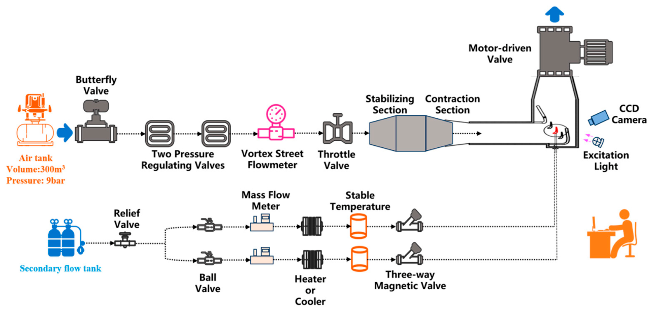
Figure 2 schematically illustrates the transonic turbine cascade employed for tip film cooling effectiveness measurements. The facility comprises a mainstream air loop and an independent coolant loop. A compressor delivers air at 0.9 MPa into a 300 m3 reservoir; dual pressure-regulating valves maintain a steady plenum pressure upstream of the tunnel. A vortex-shedding flowmeter, instrumented with temperature and pressure transducers, records the mainstream mass flow rate, from which the average velocity is inferred using the channel cross-section. Following flow conditioning and contraction, the air enters the cascade and is exhausted through a motor-actuated throttling valve.
Coolant is supplied from separate high-pressure bottles containing CO2 and the 15% SF6–85% Ar mixture. Each stream passes through a relief valve, Coriolis mass flowmeter, thermal conditioner (heater or cooler), temperature stabilisation vessel and three-way solenoid valve before entering the blade internal passages. Two independent feed lines deliver coolant to the leading-edge and trailing-edge plena. ALICAT mass flow controllers meter the individual coolant streams. A UV-LED array excites the PSP luminescent species, and a 16-bit CCD camera captures the resulting intensity distribution on the blade tip.
The cascade test section contains five blades forming four passages; the sidewalls coincide with the suction and pressure surfaces of the end blades. Boundary-layer bleeds are machined into the sidewalls to ensure periodic inlet conditions. Three combined pressure–temperature probes are located 0.5 axial chords upstream of the leading-edge plane; six static pressure taps are positioned one axial chord downstream of the trailing-edge plane. The inlet flow angle is 58°, the exit angle is 14°, and the Reynolds number based on the axial chord is 3.7 × 10⁵. The nominal exit Mach number is 1.05.
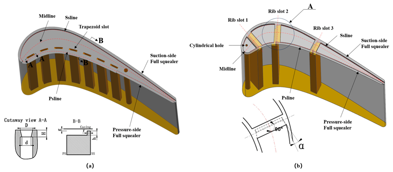
Geometric details of the cooled tips are provided in Figure 3. Both the trapezoidal-slot cooling scheme (TSCS) and the rib-slot cooling scheme (RSCS) were tested at two clearance gaps, g = 0.7% and 1.5% of the 72 mm blade span. The blade pitch is 37 mm; the true chord and axial chord are 42 mm and 28 mm, respectively. A 0.6 mm wide squealer rim surrounds the tip, and the cavity depth is 0.8 mm. Reference lines labelled Psline, Midline and Ssline denote the pressure-side, mid-span and suction-side traces.
The TSCS planform (Figure 3a) incorporates one cylindrical feed hole (Ø 1 mm) and seven trapezoidal slots. The slot width, inlet length, outlet length, pitch and height are 0.4 mm, 1.6 mm, 2.2 mm, 3.8 mm and 1.2 mm, respectively. A partial squealer occupies 40% of the pressure-side rim length, whereas a full squealer is retained on the suction side. The coolant for the five upstream slots is supplied from cavity 1 at mass flow ratio m1; the two downstream slots plus the cylindrical hole are fed from cavity 2 at ratio m2.
The RSCS planform (Figure 3b) contains three rib slots and one cylindrical hole (Ø 0.6 mm). Each rib slot has a 10° expansion angle, 1.8 mm width and 0.4 mm exit height. The cylindrical hole and rib slots 1–2 are connected to cavity 1 (mass flow ratio m1); rib slot 3 is supplied by cavity 2 (mass flow ratio m2).

2.3. Parameter Calculations

The mass flow ratios of cavity 1 to cavity 2 are given below,
m 1 = m c 1 m g r
m 2 = m c 2 m g r
where mc1, mc2, and mgr are the mass flow rates of cavity 1, cavity 2 and the mainstream, respectively. m1 is 0.17%, and m2 is 0.085%.
The inlet Reynolds number is given below,
Re = m g r C μ g A g
where C, μg and Ag denote the blade axial chord length, mainstream dynamic viscosity coefficient and cascade sectional area, respectively.
The aerodynamic loss coefficient [47,48] is calculated as follows,
ξ = 1 [ 1 ( P l o c a l P l o c a l * ) ( k 1 k ) g ] [ m g r T g , i n l e t * + m c 1 T c 1 , i n l e t * + m c 2 T c 2 , i n l e t * ] m g r T g , i n l e t * [ 1 ( P l o c a l P g , i n l e t * ) ( k 1 k ) g ] + m c 1 T c 1 , i n l e t * [ 1 ( P l o c a l P c 1 , i n l e t * ) ( k 1 k ) c 1 ] + m c 2 T c 2 , i n l e t * [ 1 ( P l o c a l P c 2 , i n l e t * ) ( k 1 k ) c 2 ]
where T* and P* are total temperature and total pressure, respectively. k denotes the specific heat ratio.

2.4. Numerical Method

Steady-state RANS equations are employed to resolve the flow field within the CFD solver. Turbulence closure is achieved with the standard k-ω model coupled to automatic near-wall treatment, while a high-speed wall heat transfer model is activated. Total energy formulation is selected for thermal computations. All transport equations are discretised using a second-order upwind scheme. The blade geometry and boundary specifications replicate those of the companion experiments. The computational mesh is generated via ICEM CFD. The numerical framework has been previously validated [28,30] and is therefore considered suitable for predicting the aero-thermal behaviour of both the trapezoidal-slot and rib-slot tip cooling configurations.

3. Results and Discussion

3.1. Investigation of the Flow Performance of the Tip with the Cooling Schemes

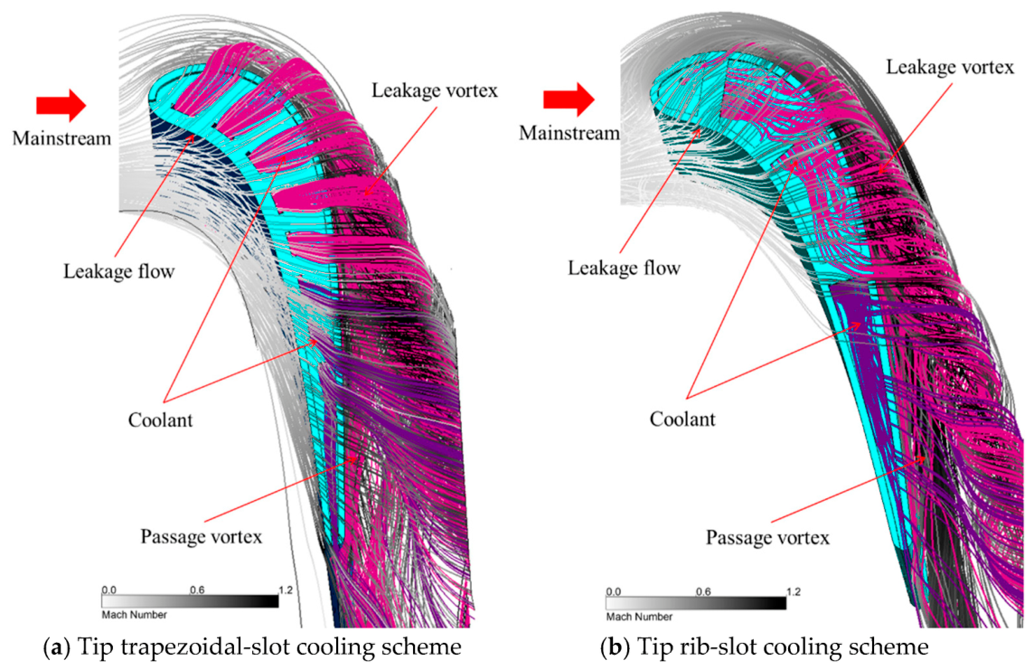
Figure 4 illustrates the streamline patterns of the TSCS and RSCS at 0.7% tip clearance; the density ratio is 1.5. A dominant leakage vortex originates near the suction surface as the clearance flow accelerates, detaching from the suction side around mid-chord. Between this vortex and the blade surface, a secondary passage vortex is established. For the TSCS (Figure 4a), coolant emerging from the trapezoidal slots is driven by the leakage stream back onto the cavity floor before exiting the clearance predominantly over the suction-side rim; a fraction of the cylindrical-hole coolant is swept out of the trailing-edge gap while the remainder is entrained by the leakage flow past the suction-side squealer. In the RSCS (Figure 4b), part of the coolant discharged from rib slots 1 and 2 is immediately carried through the clearance, whereas the remainder escapes from rib slot 2 or 3 and subsequently leaks over the suction side; a portion of the rib slot 3 coolant leaves through the trailing edge, while the cylindrical-hole jet fails to reattach to the cavity floor.
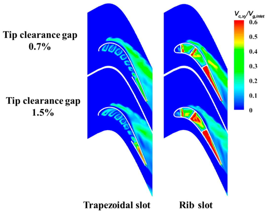
Figure 5 displays the resultant coolant velocity in the blade X-Y plane (Vc,xy normalised by the cascade inlet velocity Vg,inlet) for both schemes at a density ratio of 1.5 and clearance gaps of 0.7% and 1.5%. The section is located 0.2 mm above the tip floor. In the TSCS, high-velocity coolant pockets appear immediately downstream of each trapezoidal slot, but a low-velocity core persists at the centre of each jet due to a recirculating vortex between the coolant and the cavity floor. At the larger clearance, the resultant velocity near the trailing edge increases because the stronger leakage stream forces more coolant onto the floor. For the RSCS, elevated velocity regions are evident at the exits of all three rib slots; enlarging the clearance further augments the velocity downstream of rib slots 2 and 3. Within the trailing-edge cavity, the velocity is higher adjacent to the pressure-side rim because leakage flow reattachment blocks low-momentum fluid, deflecting it toward the pressure side. Overall, the cross-sectional resultant velocity in the TSCS is lower than that in the RSCS, especially downstream of the rib slots, although the RSCS exhibits reduced velocity near the leading edge.
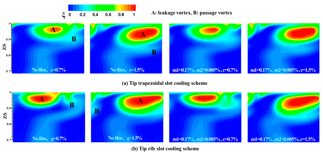
Figure 6 contours the aerodynamic loss coefficient at the computational-plane exit for both schemes at 0.7% and 1.5% clearance. Region A, characterised by a high aerodynamic loss coefficient, is generated by the leakage vortex and enlarges markedly at 1.5% clearance. A secondary loss core attributable to the passage vortex is also present, but its spatial extent is smaller than that of the leakage vortex loss region. Increasing clearance displaces the centre of region A away from the shroud. For the RSCS at 0.7% clearance, the passage vortex loss with coolant injection exceeds that of the uncooled case. The RSCS also produces a larger high aerodynamic loss coefficient region A than the TSCS, an effect linked to the differing squealer configurations; the partial pressure-side squealer of the TSCS strengthens a suction-side corner vortex that provides a local sealing action, thereby moderating the loss.
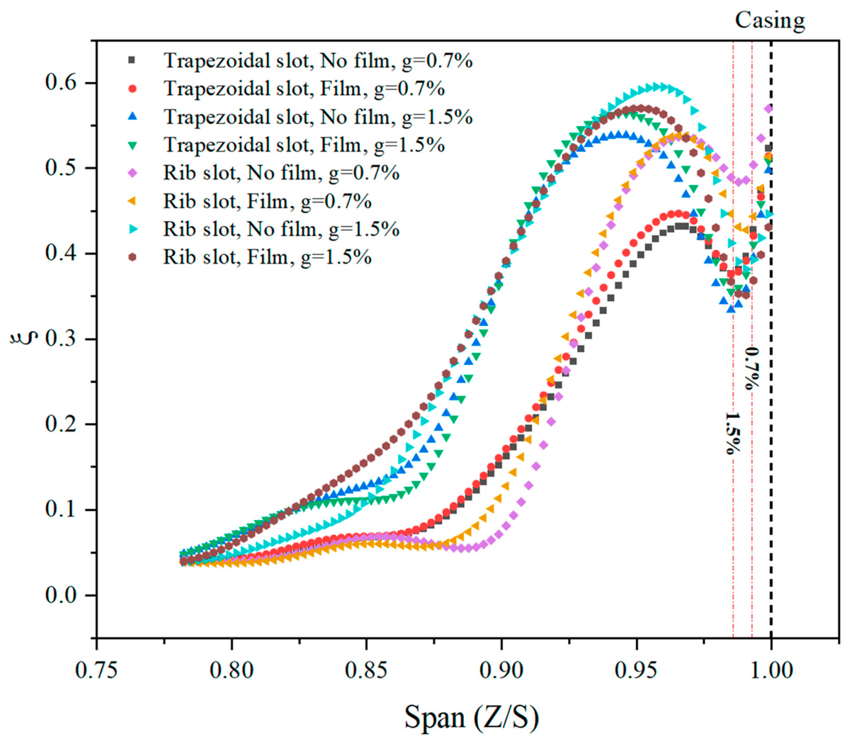
Figure 7 presents the pitch-wise averaged loss coefficient at the exit plane; Z/S = 1 corresponds to the shroud, and the 0.7% and 1.5% clearance cases are indicated by red dashed lines. For both schemes, increasing clearance reduces the pitch-wise averaged loss coefficient in the region Z/S > 0.98 because the leakage vortex core migrates away from the shroud, shifting the peak value of the pitch-wise averaged loss coefficient radially outward. At 0.7% clearance, the TSCS yields a lower pitch-wise averaged loss coefficient than the RSCS, particularly adjacent to the shroud; near the shroud, coolant injection raises the pitch-wise averaged loss coefficient for the TSCS but lowers it for the RSCS. At 1.5% clearance, the RSCS continues to exhibit a higher pitch-wise averaged loss coefficient than the TSCS. Collectively, these results demonstrate that the TSCS confers superior aerodynamic performance relative to the RSCS, with the benefit most pronounced under large clearance conditions.
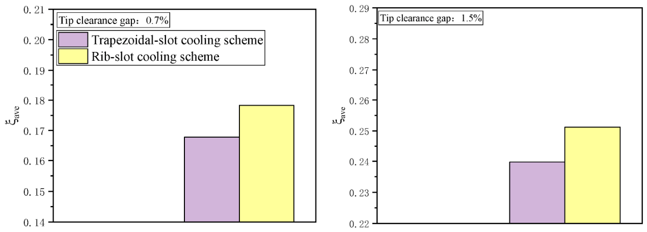
Figure 8 shows the distribution of the area-averaged aerodynamic loss coefficient on the cascade passage surface with different tip cooling structures. Because the aerodynamic loss coefficients within the cascade channels of different tip cooling structures are nearly identical in the region where Z/S < 0.715, to highlight the variations in the average aerodynamic loss coefficient caused by different tip air-cooled structures within the cascade channels, the aerodynamic loss coefficients in the region where 0.715 < Z/S < 1 are selected for area averaging in Figure 8. As can be seen from the figure, the aerodynamic loss coefficient is lowest for the trapezoidal-slot cooling scheme, indicating that this structure achieves the best aerodynamic performance.
At the condition of a tip clearance height of 1.5%, the area-averaged aerodynamic loss coefficient of the cascade passage surface for the trapezoidal-slot cooling scheme is reduced by approximately 4.6% compared to the rib-slot cooling scheme. At a tip clearance height of 0.7%, the average aerodynamic loss coefficient of the cascade passage surface for the trapezoidal-slot cooling scheme is reduced by approximately 5.9% compared to the rib-slot cooling scheme.

3.2. Investigation of the Film Cooling Performance of the Tip with the Cooling Schemes

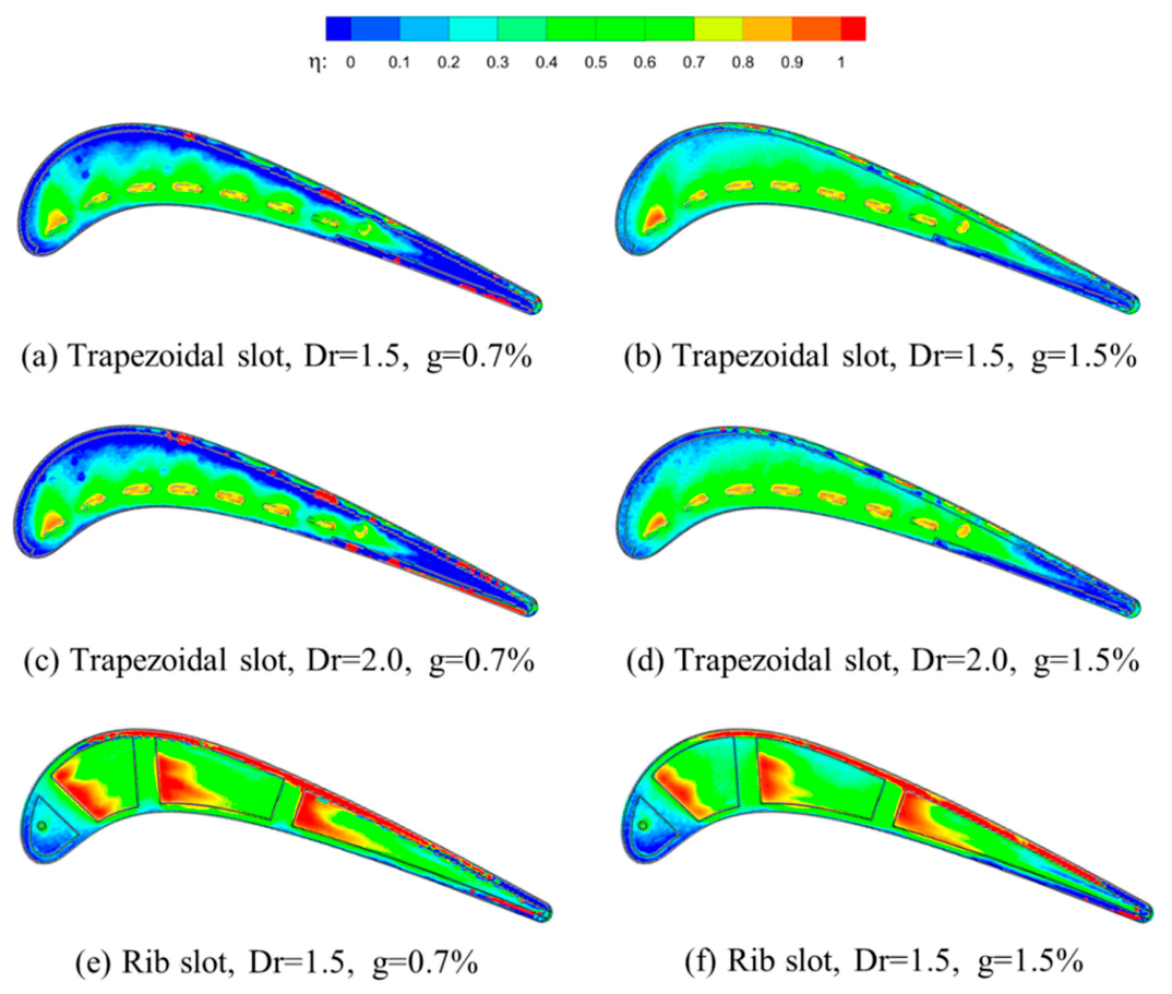
Figure 9 illustrates the experimentally determined adiabatic film cooling effectiveness (η) contours on the blade tip. Inspection of Figure 9a–d reveals that elevating the density ratio from 1.5 to 2.0 exerts a negligible influence on the η distribution for the TSCS at both the 0.7% and 1.5% tip-clearance-to-span ratios. As for the tip-clearance-to-span ratio of 0.7%, the trailing-edge region remains devoid of coolant because the weakened leakage stream is insufficient to pressurise the cylindrical-hole effluent against the cavity floor. Consequently, the coolant is swept over the suction-side squealer and expelled. Expanding the tip-clearance-to-span ratio from 0.7% to 1.5% markedly enhances film cooling effectiveness, particularly along the suction-side rim and at the trailing edge, as the intensified leakage drives a larger fraction of coolant onto the tip floor. Nevertheless, even at the larger clearance, a local film cooling effectiveness minimum persists adjacent to the suction-side squealer near the trailing edge; leakage-flow reattachment at this location blocks low-momentum coolant and deflects it toward the pressure-side cavity. A contiguous film is sustained on the pressure side by a recirculating vortex that transports coolant upstream of the trapezoidal slots, ensuring coverage in that region.
Figure 9e,f reveal a zone of elevated film cooling effectiveness at the rib-slot exit, which diminishes as the tip clearance widens. The enlargement accelerates coolant dispersion through intensified leakage. Within the cavity, the pressure-side squealer rim attains higher effectiveness than its suction-side counterpart because the leakage reattachment drives the coolant toward the pressure wall. Conversely, at the leading-edge cavity, the pressure-side rim exhibits lower effectiveness than the suction-side rim. An increase in tip clearance exerts an adverse influence on the film cooling performance over the rib-slot upper surface.
Both the trapezoidal-tip-slot and rib-slot cooling configurations are capable of delivering complete film coverage over the blade tip. The rib-slot approach yields appreciably higher adiabatic effectiveness across the mid-chord and trailing-edge zones relative to the trapezoidal-slot scheme. However, a region of reduced effectiveness appears at the leading edge of the rib-slot concept. The principal merit of the trapezoidal-slot geometry lies in its uniformity of film coverage.
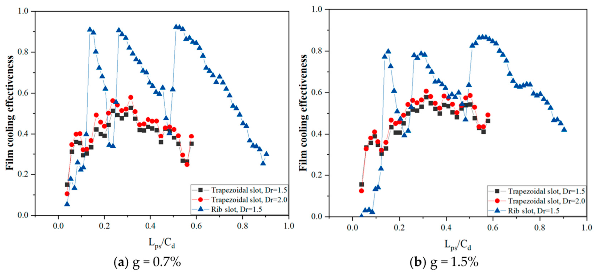
Figure 10 illustrates the adiabatic film effectiveness along the blade tip Ps-line at clearance gaps of 0.7% and 1.5%. For the rib-slot configuration, effectiveness peaks at each rib-slot orifice and decays steeply in the streamwise direction. Enlarging the clearance exerts an adverse influence on the effectiveness emanating from the three rib-slot exits; nevertheless, the trailing-edge Ps-line effectiveness at 1.5% clearance surpasses that at 0.7% because the increased leakage drives additional coolant toward the pressure-side squealer rim. In the trapezoidal-slot scheme, a higher density ratio marginally reduces Ps-line effectiveness, whereas a wider clearance produces a beneficial rise, most noticeable over the mid-chord region. At the leading edge, the rib-slot arrangement delivers lower Ps-line effectiveness than its trapezoidal-slot counterpart. However, for lps/Cd > 0.1, the rib-slot approach achieves markedly higher values, especially at the three slot exits. Relative to the rib-slot concept, the trapezoidal-slot geometry furnishes a more uniform Ps-line effectiveness distribution.
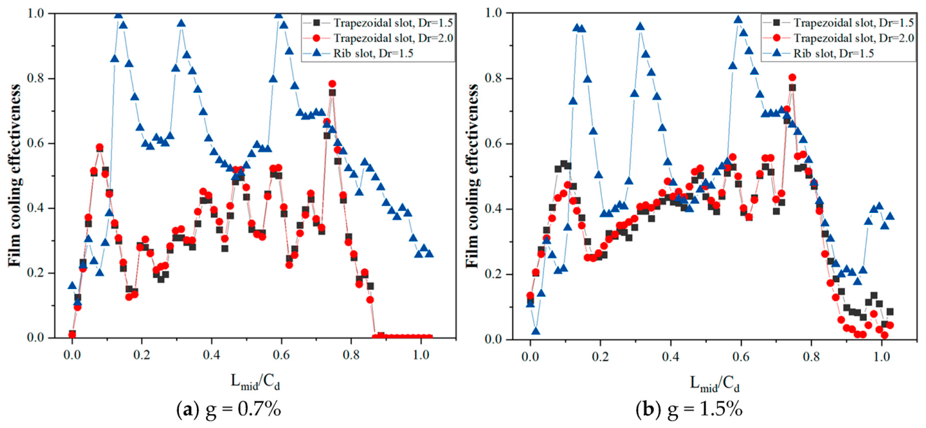
Figure 11 displays the adiabatic film effectiveness distribution along the mid-span line (Midline) of the blade tip for clearance gaps of 0.7% and 1.5%. As evident in Figure 9a, elevating the density ratio exerts a marginal influence on the Midline effectiveness of the trapezoidal-slot scheme; nevertheless, at 1.5% clearance, the elevated density ratio slightly enhances Midline performance. The enlarged clearance consistently improves Midline effectiveness for the trapezoidal-slot configuration because intensified leakage drives additional coolant toward the cavity floor. A local effectiveness peak is observed at the smaller clearance, whereas it vanishes under the larger-clearance condition, an effect ascribed to the altered leakage flow strength. For the rib-slot arrangement, effectiveness approaches unity at each rib-slot exit, followed by a rapid streamwise decay until the subsequent slot. Expanding the clearance markedly reduces Midline effectiveness on the rib-slot upper wall, as the coolant is rapidly dispersed by the stronger leakage.
At the leading edge of the tip, the trapezoidal-slot configuration yields superior Midline adiabatic effectiveness relative to the rib-slot concept. For lmid/Cd > 0.12, the rib-slot scheme attains appreciably higher Midline effectiveness than its trapezoidal-slot counterpart; nevertheless, the spatial uniformity of the rib-slot Midline distribution is comparatively poorer.
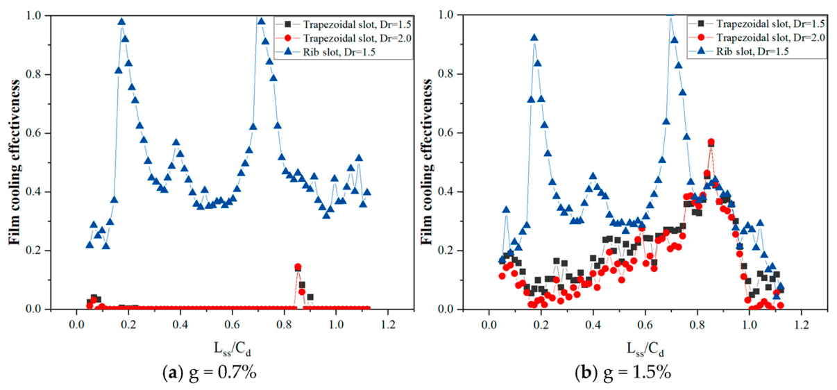
Figure 12 illustrates the adiabatic film effectiveness distribution along the suction-side line (Ss-line) of the blade tip at clearance gaps of 0.7% and 1.5%. For the trapezoidal-slot configuration, the Ss-line remains devoid of coolant coverage because the leakage trajectory is unable to deflect the coolant toward the suction-side cavity floor; instead, the majority of the coolant is swept through the clearance. Enlarging the gap exerts a favourable influence on Ss-line effectiveness, most noticeably in the vicinity of the cylindrical film hole. An elevated density ratio diminishes the Ss-line effectiveness of the trapezoidal-slot scheme, since the higher-density, lower-momentum coolant is readily scattered by the leakage, curtailing its lateral penetration. In contrast, the rib-slot concept experiences an adverse effect from the larger clearance, particularly at the trailing edge, as the intensified leakage rapidly disperses the coolant and, via reattachment, drives it toward the pressure side. Across the entire Ss-line, and especially at the smaller clearance, the rib-slot arrangement delivers markedly higher effectiveness than the trapezoidal-slot alternative.

4. Conclusions

The adiabatic effectiveness and associated flow physics of the trapezoidal-tip-slot and rib-tip-slot cooling concepts are investigated both numerically and experimentally. Pressure-sensitive paint (PSP) is employed to quantify the tip film cooling performance. Aero-thermal behaviour is examined for two coolant-to-mainstream density ratios (1.5 and 2.0) and two tip clearance heights (0.7% and 1.5% chord) under transonic conditions. The principal findings are:
  • Both the trapezoidal-slot and rib-slot geometries are capable of delivering complete film coverage over the blade tip.
  • Relative to the trapezoidal-slot scheme, the rib-slot configuration yields appreciably higher effectiveness over the mid-chord and trailing-edge regions; conversely, a region of reduced effectiveness persists at the leading edge of the rib-slot concept.
  • The trapezoidal-slot approach is distinguished by its spatially uniform film coverage.
  • With respect to aerodynamic performance, the trapezoidal-slot scheme offers a beneficial effect compared with the rib-slot arrangement, an advantage that becomes more pronounced at the larger clearance gap.

Author Contributions

Software, J.X.; investigation, J.X.; writing—original draft, B.-L.Z.; visualisation, X.-P.H. All authors have read and agreed to the published version of the manuscript.

Funding

This research was funded by the Natural Science Foundation of Hunan Province, China (Grant No.2024JJ6464), the Youth Independent Innovation Science Fund Project (Grant No.2023-039), and the Innovation Research Foundation of the National University of Defense Technology 25-XX-DFXJS-XX.

Data Availability Statement

The original contributions presented in this study are included in this article. Further inquiries can be directed to the corresponding author.

Conflicts of Interest

The authors declare no conflicts of interest.

Nomenclature

XX axis direction
YY axis direction
ZZ axis direction, blade spanwise direction
TTemperature
COxygen concentration, blade axial chord length
WMolar mass
pOxygen partial pressure
ILuminous intensity
AConstant
BConstant
SBlade span length
gTip clearance gap
RSCSRib-slot cooling scheme
TSCSTrapezoidal-slot cooling scheme
wSlot width of the TSCS
dInlet length of the TSCS
DOutlet length of the TSCS
pSpacing of the TSCS
HHeight of the TSCS
rTip squealer rim width
mMass flow
VVelocity
PslinePressure-side line
MidlineMiddle line
SslineSuction-side line
Greek symbols
ξ Aerodynamic loss coefficient
ηFilm cooling effectiveness
Subscripts
gMainstream
cCoolant
wMixture gas
RReference

References

  1. Bathie, W.M. Fundamentals of Gas Turbines, 2nd ed.; John Wiley & Sons: New York, NY, USA, 1996. [Google Scholar]
  2. Li, J.T.; E, J.Q.; Ding, J.J.; Cai, L.; Luo, B. Investigation on thermophotovoltaic performance enhancement of the hydrogen fueled micro combustors with the center-cleared twisted tapes for micro-thermophotovoltaic system. Appl. Therm. Eng. 2025, 264, 125483. [Google Scholar] [CrossRef]
  3. Li, J.T.; E, J.Q.; Ding, J.J.; Cai, L.; Luo, B. Effects of deformed twisted tapes on thermal performance enhancement of hydrogen fueled micro combustor for micro-thermophotovoltaic system. Appl. Therm. Eng. 2025, 264, 125413. [Google Scholar] [CrossRef]
  4. Kou, C.F.; Zeng, S.Q.; Chen, X.G.; E, J.Q.; Ma, Y.J. Effects of air–fuel ratio on combustion performance enhancement and emission reduction of the methanol–diesel dual-fuel engine. Can. J. Chem. Eng. 2026, 1–9. [Google Scholar] [CrossRef]
  5. Zhang, B.L.; Xia, J.; Zhang, F.Z.; Shen, Z.Q.; Zhang, F. Investigation on the Effect of Recuperator Design on the Supercritical Carbon Dioxide Power Cycle for Hypersonic Vehicles. Aerosp. Sci. Technol. 2026, 177, 112314. [Google Scholar] [CrossRef]
  6. Ren, L.; Wen, R.; Zheng, D.; Sun, J. The Influence of Detached Rib Locations on the Channel Thermal Performance. Heat Transf. Eng. 2026, 1–18. [Google Scholar] [CrossRef]
  7. Zhou, J.; Cao, L.; Liao, G.; Zhang, F. Performance analysis of a He-Xe Brayton cycle based on recuperator configuration for nuclear space power systems. Appl. Therm. Eng. 2026, 292, 130292. [Google Scholar] [CrossRef]
  8. Dai, H.; Zhang, F.; Liao, G.; E, J. Performance analysis and improvement of the battery thermal management system based on topology-optimized cold plates using sCO2 as coolant. Renew. Energy 2026, 266, 125731. [Google Scholar] [CrossRef]
  9. You, M.; Feng, M.; Zhang, F.; Liao, G. Numerical investigation on the unsteady flow and coupled heat transfer characteristics between supercritical carbon dioxide and pulsating flow of water within a PCHE under offshore conditions. Int. Commun. Heat Mass Transf. 2026, 172, 110249. [Google Scholar] [CrossRef]
  10. Song, H.; Yan, Y.; Zhang, F.; Liao, G.; E, J. Numerical investigation on the unsteady flow and heat transfer characteristics of supercritical carbon dioxide within a vertical tube under offshore conditions. Appl. Therm. Eng. 2025, 274, 126796. [Google Scholar] [CrossRef]
  11. Zhang, B.L.; Zhang, F. Investigations on Flow and Heat Transfer Characteristics of Supercritical Carbon Dioxide Inside Scramjet Cooling Channel Under Different Arrangements. Energies 2026, 19, 3282. [Google Scholar] [CrossRef]
  12. Zhang, B.L.; Xia, J.; Tao, W.; Shen, Z.Q.; Zhang, F.Z.; Zhang, F. Film Cooling Characteristics of a Pintle in a Thrust-Controlled Solid Rocket Motor. Aerosp. Sci. Technol. 2026, 168, 111219. [Google Scholar] [CrossRef]
  13. Zhou, Z.H.; Bai, B.; Li, Z.G.; Li, J. Numerical investigation on film cooling performance and heat transfer characteristics of turbine blade squealer tips with ribs above the film holes. Int. J. Therm. Sci. 2025, 210, 109653. [Google Scholar] [CrossRef]
  14. Bunker, R.S.; Bailey, J.C.; Ameri, A.A. Heat transfer and flow on the first-stage blade tip of a power generation gas turbine: Part 1—Experimental results. J. Turbomach. 2000, 122, 263–271. [Google Scholar]
  15. Park, J.S.; Lee, D.H.; Rhee, D.H.; Kang, S.H. Heat transfer and effectiveness on the film cooled tip and inner rim surfaces of a turbine blade. In ASME Paper GT2010-23203; ASME: New York, NY, USA, 2010. [Google Scholar]
  16. Naik, S.; Georgakis, C.; Hofer, T.; Lengani, D. Heat transfer and film cooling of blade tips and endwalls. J. Turbomach. 2011, 134, 041004. [Google Scholar] [CrossRef]
  17. Kwak, J.S.; Ahn, J.; Han, J.C. Effects of rim location, rim height, and tip clearance on the tip and near tip region heat transfer of a gas turbine blade. Int. J. Heat Mass Transf. 2004, 47, 5651–5663. [Google Scholar] [CrossRef]
  18. Kwak, J.S.; Ahn, J.; Han, J.C. Heat transfer coefficients on the squealer tip and near-tip regions of a gas turbine blade with single or double squealer. J. Turbomach. 2003, 125, 778–787. [Google Scholar] [CrossRef]
  19. Buske, C.; Ullrich, W.C.; Roehle, I. Numerical study of incidence angles and gap heights in turbine cascades and rotors on tip clearance losses. In ASME Paper GT2013-94872; ASME: New York, NY, USA, 2013. [Google Scholar]
  20. Mischo, B.; Behr, T.; Abhari, R.S. Flow physics and profiling of recessed blade tips: Impact on performance and heat load. J. Turbomach. 2008, 130, 021008. [Google Scholar] [CrossRef]
  21. Mischo, B.; Burdet, A.; Abhari, R.S. Influence of stator-rotor interaction on the aerothermal performance of recess blade tips. J. Turbomach. 2011, 133, 011023. [Google Scholar]
  22. Huang, M.; Li, Z.G.; Li, J. Investigations on the aerothermal performance of the turbine blade winglet squealer tip within an uncertainty framework. Aerosp. Sci. Technol. 2022, 123, 107506. [Google Scholar] [CrossRef]
  23. Kim, Y.W.; Downs, J.P.; Soechting, F.O.; Steuber, G.D.; Tanrikut, S. A summary of the cooled turbine blade tip heat transfer and film effectiveness investigations performed by Dr. D. E. Metzger. J. Turbomach. 1995, 117, V004T09A022. [Google Scholar] [CrossRef]
  24. Kim, Y.M.; Metzger, D.E. Heat transfer and effectiveness on film cooled turbine blade tip model. J. Turbomach. 1995, 117, 12–21. [Google Scholar] [CrossRef]
  25. Christophel, J.R.; Thole, K.A.; Cunha, F.J. Cooling the tip of a turbine blade using pressure side holes, part i—Adiabatic effectiveness measurements. J. Turbomach. 2005, 127, 270–277. [Google Scholar] [CrossRef]
  26. Christophel, J.R.; Thole, K.A.; Cunha, F.J. Cooling the tip of a turbine blade using pressure side holes, part ii—Heat transfer measurements. J. Turbomach. 2005, 127, 278–286. [Google Scholar] [CrossRef]
  27. Christophel, J.R.; Thole, K.A.; Cunha, F.J. Measured adiabatic effectiveness and heat transfer for blowing from the tip of a turbine blade. J. Turbomach. 2005, 127, 251–262. [Google Scholar] [CrossRef]
  28. Ligrani, P.; Collopy, H.; Xu, H.Z.; Fox, M. Tip gap and coolant mass flux ratio effects on film cooling effectiveness, coefficients of convection, and net heat flux reduction along a transonic turbine airfoil. Int. J. Heat Fluid Flow 2025, 116, 109989. [Google Scholar] [CrossRef]
  29. Xu, K.W.; He, K.; Yan, X. Effects of cooling hole blockage on heat transfer and film cooling effectiveness of gas turbine squealer tip. Int. J. Heat Fluid Flow 2025, 112, 109678. [Google Scholar] [CrossRef]
  30. Tao, Y.; Liu, Z.; Liu, Y.D.; Zhang, W.; Feng, Z. An investigation on film cooling and aerodynamic performance of squealer blade tip with inclined cavity bottom. Int. J. Heat Fluid Flow 2024, 107, 109434. [Google Scholar] [CrossRef]
  31. Li, C.; Xiang, J.C.; Song, L.M.; Li, J. An aerothermal analysis of the effects of tip gap height and cavity depth of a gas turbine blade. Int. J. Therm. Sci. 2020, 158, 106521. [Google Scholar] [CrossRef]
  32. Zhou, Z.H.; Zhang, K.Y.; Huang, M.; Li, Z.; Li, J. Numerical investigations on film cooling effectiveness and heat transfer performance of inclined film hole on the turbine blade squealer tip with plasma actuation. Aerosp. Sci. Technol. 2024, 151, 109283. [Google Scholar] [CrossRef]
  33. Zamiri, A.; You, S.J.; Chun, J.T. Large eddy simulation of unsteady turbulent flow structures and film-cooling effectiveness in a laidback fan-shaped hole. Aerosp. Sci. Technol. 2020, 100, 105737. [Google Scholar] [CrossRef]
  34. Gunady, E.; Milani, P.M.; Banko, A.J.; Elkins, C.J.; Eaton, J.K. Velocity and concentration field measurements and large eddy simulation of a shaped film cooling hole. Int. J. Heat Fluid Flow 2021, 90, 108837. [Google Scholar] [CrossRef]
  35. Tao, Y.; Liu, Z.; Han, Y.H.; Liu, Y.; Feng, Z. An investigation on aerothermal performance of squealer tip with baffle arranged above film holes-Part I: Film cooling performance. Int. J. Heat Fluid Flow 2025, 115, 109881. [Google Scholar] [CrossRef]
  36. Wheeler, A.P.; Saleh, Z. Effect of cooling injection on transonic tip flows. J. Propul. Power. 2013, 29, 1374–1381. [Google Scholar] [CrossRef]
  37. Zhou, C. Thermal performance of transonic cooled tips in a turbine cascade. J. Propuls. Power 2015, 31, 1268–1280. [Google Scholar] [CrossRef]
  38. Zhou, C.; Hodson, H.; Tibbott, I.; Stokes, M. Effects of endwall motion on the aero-thermal performance of a winglet tip in a HP turbine. J. Turbomach. 2012, 134, 061036. [Google Scholar] [CrossRef]
  39. Li, J.; Du, K.; Song, L. Effects of tip cavity geometries on the aerothermal performance of the transonic turbine blade with cavity tip. J. Power Energy. 2016, 230, 319–331. [Google Scholar] [CrossRef]
  40. Zhang, B.L.; Zhu, H.R.; Yao, C.Y.; Liu, C.L. Investigation on aerothermal performance of a rib-slot scheme on the multi-cavity tip of a gas turbine blade. Int. J. Heat Mass Transf. 2021, 176, 121408. [Google Scholar] [CrossRef]
  41. Zhang, B.L.; Xia, J. Film Cooling Performance of the Moving Pintle in a Thrust-Controlled Solid Rocket Motor. Aerospace 2026, 13, 651. [Google Scholar] [CrossRef]
  42. Zhang, B.L.; Yao, C.Y.; Zhu, H.R.; Liu, C.L.; Sunden, B. Experimental study on film cooling performance of a turbine blade tip with a trapezoidal slot cooling scheme in transonic flow using PSP technique. Exp. Therm. Fluid Sci. 2022, 130, 110513. [Google Scholar] [CrossRef]
  43. Zhang, B.L.; Xia, J.; Yang, L.P.; Xi, Y.-Z.; Gao, J.-W.; Zhu, H.-R. Investigation of aerothermal performance of blade tip with conical holes in transonic flow. Aerosp. Sci. Technol. 2023, 142, 108590. [Google Scholar] [CrossRef]
  44. Han, J.C.; Rallabandi, A.P. Turbine blade film-cooling using PSP technique. Front. Heat Pipes 2010, 1, 227–237. [Google Scholar] [CrossRef]
  45. Chen, D.W.; Zhu, H.R.; Liu, C.L.; Li, H.-T.; Li, B.-R.; Zhou, D.-E. Combined effects of unsteady wake and free-stream turbulence on turbine blade film-cooling with laid-back fan-shaped holes using PSP technique. Int. J. Heat Mass Transf. 2019, 133, 382–392. [Google Scholar] [CrossRef]
  46. Coleman, H.W.; Steele, W.G. Experimentation and Uncertainty Analysis for Engineers; John Wiley & Sons, Inc.: Hoboken, NJ, USA, 1989; Chapters 3 and 4. [Google Scholar]
  47. Young, J.B.; Horlock, J.H. Defining the Efficiency of a Cooled Turbine. J. Turbomach. 2006, 128, 658–667. [Google Scholar] [CrossRef]
  48. Hofer, T.; Arts, T. Aerodynamic Investigation of the Tip Leakage Flow for Blades with Different Tip Squealer Geometries at Transonic Conditions. In ASME Paper GT2009-59909; ASME: New York, NY, USA, 2009. [Google Scholar]
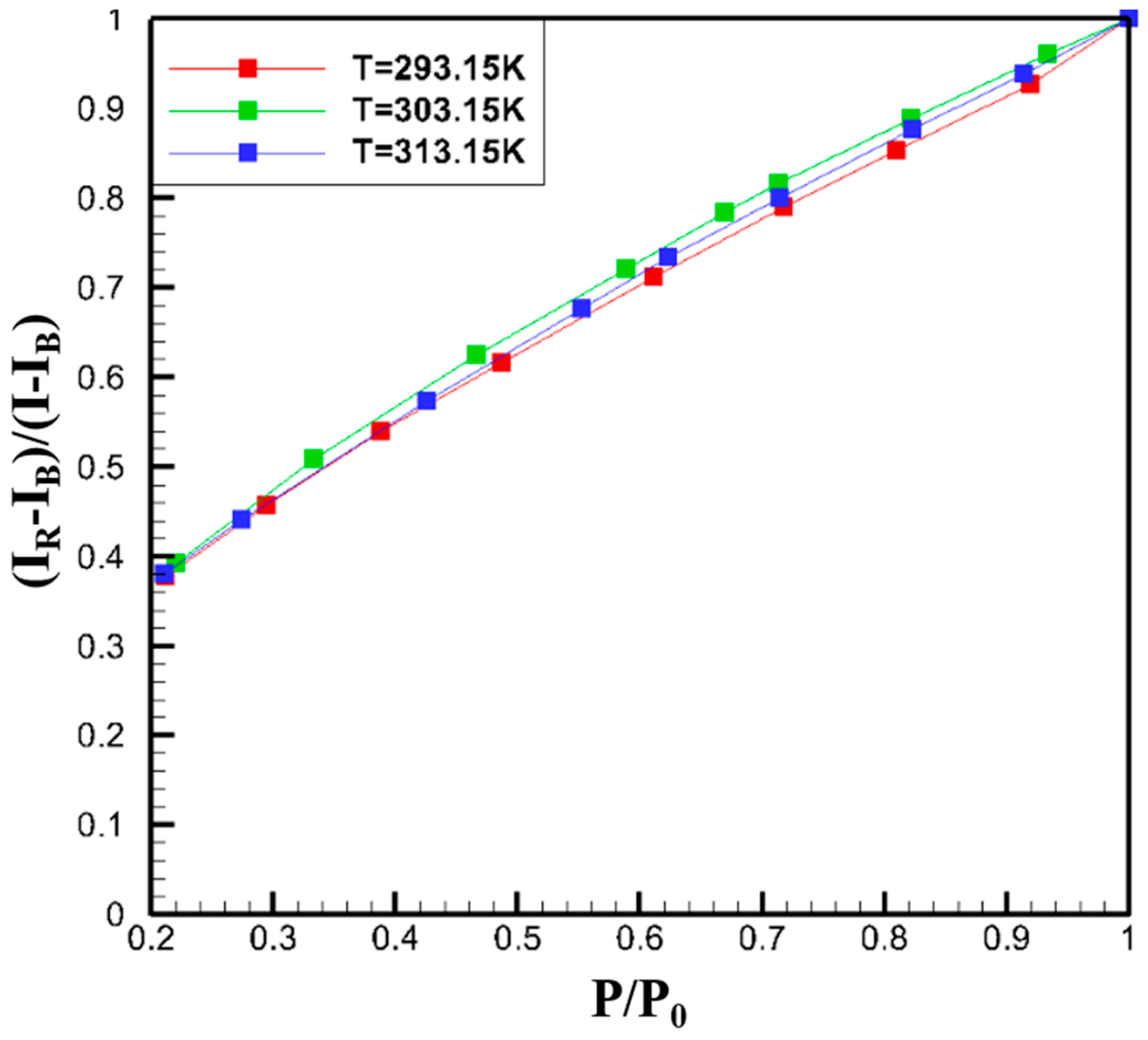
Figure 1. PSP calibration.
Processes 14 02422 g001
Figure 2. Experimental system.
Processes 14 02422 g002
Figure 3. Blade tip cooling scheme. (a) Planform of the tip trapezoidal-slot cooling scheme; (b) Planform of the tip rib-slot cooling scheme.
Processes 14 02422 g003
Figure 4. Streamlines of the tip trapezoidal-slot cooling scheme and tip rib-slot cooling scheme.
Processes 14 02422 g004
Figure 5. The coolant resultant velocity in the X and Y directions at a density ratio of 1.5.
Processes 14 02422 g005
Figure 6. The aerodynamic loss coefficient distribution on the computational domain outlet.
Processes 14 02422 g006
Figure 7. The pitch-wise averaged aerodynamic loss coefficient on the computational domain outlet.
Processes 14 02422 g007
Figure 8. Area-averaged aerodynamic loss coefficient on the cascade passage surface with different tip cooling structures.
Processes 14 02422 g008
Figure 9. Film cooling effectiveness distribution on the blade tip obtained by the experimental method.
Processes 14 02422 g009
Figure 10. Film cooling effectiveness distribution on the Psline of the blade tip.
Processes 14 02422 g010
Figure 11. Film cooling effectiveness distribution on the Midline of the blade tip.
Processes 14 02422 g011
Figure 12. Film cooling effectiveness distribution on the Ssline of the blade tip.
Processes 14 02422 g012
Disclaimer/Publisher’s Note: The statements, opinions and data contained in all publications are solely those of the individual author(s) and contributor(s) and not of MDPI and/or the editor(s). MDPI and/or the editor(s) disclaim responsibility for any injury to people or property resulting from any ideas, methods, instructions or products referred to in the content.