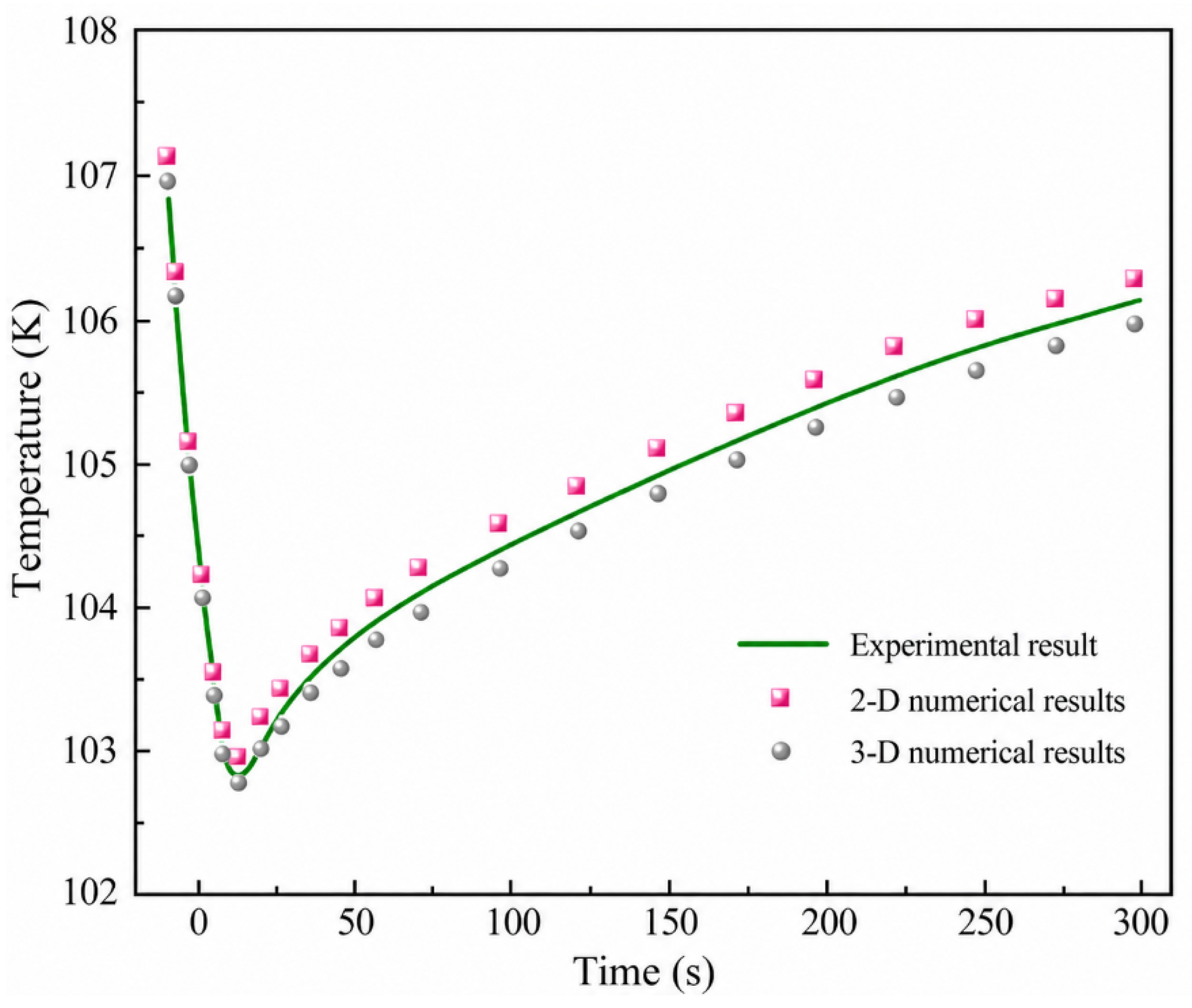
1. Introduction
In recent years, considerable attention has been paid to the filling and thermal management of cryogenic hydrogen storage tanks because the filling process involves strong coupling among gas–liquid two-phase flow, heat transfer, phase change, and pressure evolution [
1,
2,
3].
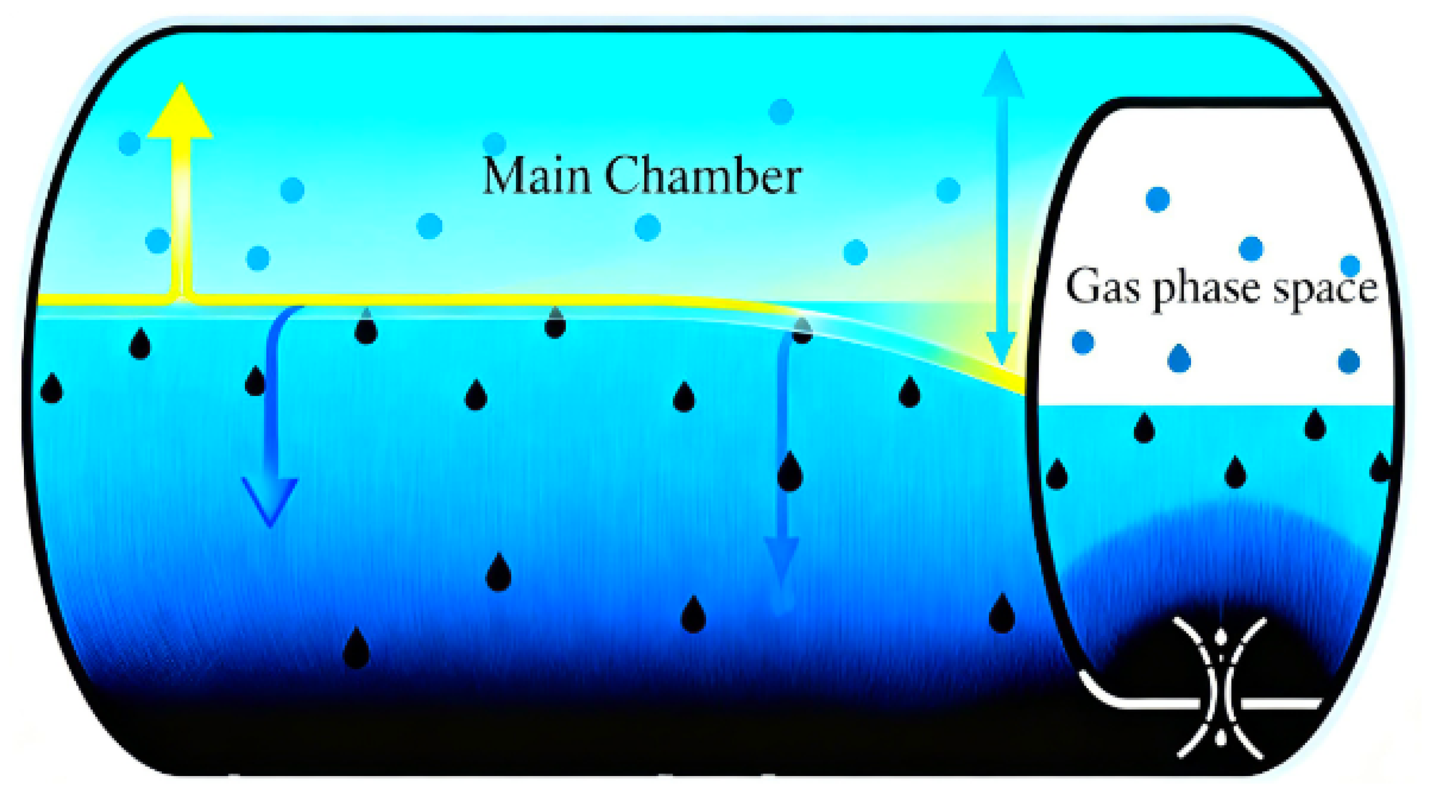
During liquid hydrogen filling, the gas–liquid two-phase regions inside the cylinder change dynamically, and physical parameters such as pressure and temperature are coupled with complex heat and mass transfer processes. Because liquid hydrogen has an extremely low temperature, approximately 20 K, a small latent heat of vaporization, and a saturation pressure that is sensitive to temperature, even a slight thermal disturbance can induce obvious evaporation, condensation, or flash evaporation, leading to rapid changes in the internal state of the cylinder. From the perspective of heat transfer, when low-temperature liquid hydrogen enters the relatively warm cylinder, it exchanges heat strongly with the original gaseous hydrogen, the inner wall, and local high-temperature regions. In the initial stage, wall cooling is accompanied by wall evaporation or local boiling, which increases the gas-phase mass and causes a rapid pressure rise. As liquid hydrogen accumulates, the heat transfer process gradually changes to liquid-phase convective heat transfer, while the gas-phase region is jointly affected by the gas–liquid interface, the wall, and gas compression. From the perspective of mass transfer, three phase change processes exist during filling: liquid hydrogen flash evaporation, liquid-phase evaporation, and gas-phase condensation. Evaporation and condensation compete with each other. Wall heat input and liquid hydrogen heating promote evaporation, whereas the cooling effect of low-temperature liquid hydrogen on the gas phase promotes condensation. If insufficient gas-phase safety space is reserved, overfilling or a rapid pressure rise may occur. Therefore, liquid hydrogen filling is essentially a complex coupled process of unsteady energy exchange and mass transfer between a low-temperature liquid and a warm vessel, as shown in
Figure 1.
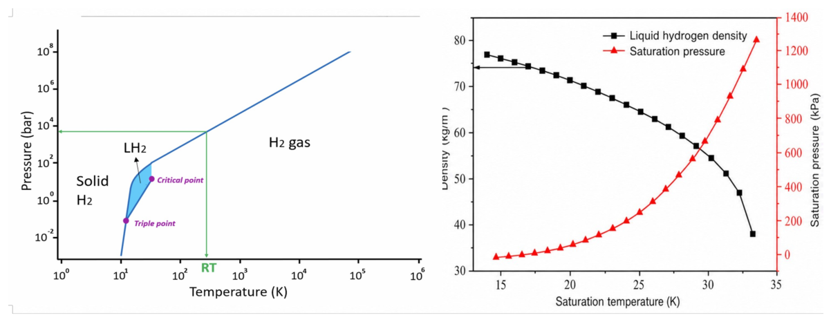
Liquid hydrogen (LH
2) exhibits a normal boiling point of only 20 K at atmospheric pressure, creating a significant temperature gradient of approximately 250 K relative to ambient conditions [
4,
5,
6,
7]. Owing to its low latent heat of vaporization, LH
2 is highly prone to flash evaporation during the initial refueling phase. Vaporized hydrogen rapidly fills the gaseous phase space at the top of the storage tank, inducing an exponential rise in system pressure. Once the pressure exceeds the maximum allowable working pressure, the pressure relief device may be actuated repeatedly, resulting not only in the loss of hydrogen mass but also in a risk of overfilling due to rapid refueling within a confined space.
In recent years, extensive research has been undertaken globally on the refueling process of cryogenic liquids, focusing on heat and mass transfer mechanisms, phase change behavior, and structural effects. Moran et al. [
8], using NASA’s Cryogenic Components Laboratory (CCL) platform, performed ventless filling experiments on small stainless-steel LH
2 tanks, systematically investigating the effects of filling method, inlet temperature, mass flow rate, and initial wall temperature on the filling dynamics, and provided in-depth analysis of the pressure evolution curves. Ma et al. [
9] developed a numerical model for a vertically oriented liquid nitrogen vessel, analyzing its thermal behavior and stress characteristics during filling, and demonstrated the model’s predictive capability for transient thermal fields and thermo-mechanical responses. Gile et al. [
10] employed a finite difference method to construct a cryogenic system model and simulated the thermodynamic behavior during ventless filling, highlighting the significant impacts of fluid properties and tank geometry on refueling performance. Ferrin et al. [
11] conducted two-dimensional CFD simulations on a 0.5 m vertical LNG tank, exploring the coupled effects of initial fill level and insulation thickness on pressure, temperature, and boil-off losses. Wang et al. [
12] performed ground-based experiments using liquid nitrogen to compare system responses under both vented and ventless filling conditions.
In summary, previous studies have investigated cryogenic liquid filling methods, filling rates, tank cooling processes, pressure responses, and phase change heat transfer characteristics. These studies provide an important basis for analyzing the mechanism and numerical simulation of no-vent filling processes for cryogenic fluids. However, most existing research focuses on conventional cryogenic tanks or no-vent filling processes, while relatively limited attention has been paid to the structural role of the gas-phase safety space inside vehicle-mounted liquid hydrogen cylinders. In particular, under overfilling conditions, how the gas-phase space affects the distribution of liquid hydrogen between the main chamber and the local chamber, and how it changes the evolution of the gas–liquid interface, pressure rise, and temperature variation, still require systematic investigation. Therefore, in this study, a 34 L vehicle-mounted liquid hydrogen cylinder is taken as the research object. A non-isothermal two-dimensional numerical model considering gas–liquid two-phase flow, heat transfer, and phase change is established. The filling processes with and without a gas phase space are compared under different filling rates. The effects of the gas-phase space on phase evolution, liquid hydrogen volume distribution, pressure response, and temperature variation are analyzed, providing a reference for the design of the gas-phase safety space and the control of filling rates in liquid hydrogen cylinders.
3. Results and Discussion
3.1. Gas–Liquid Distribution Contours
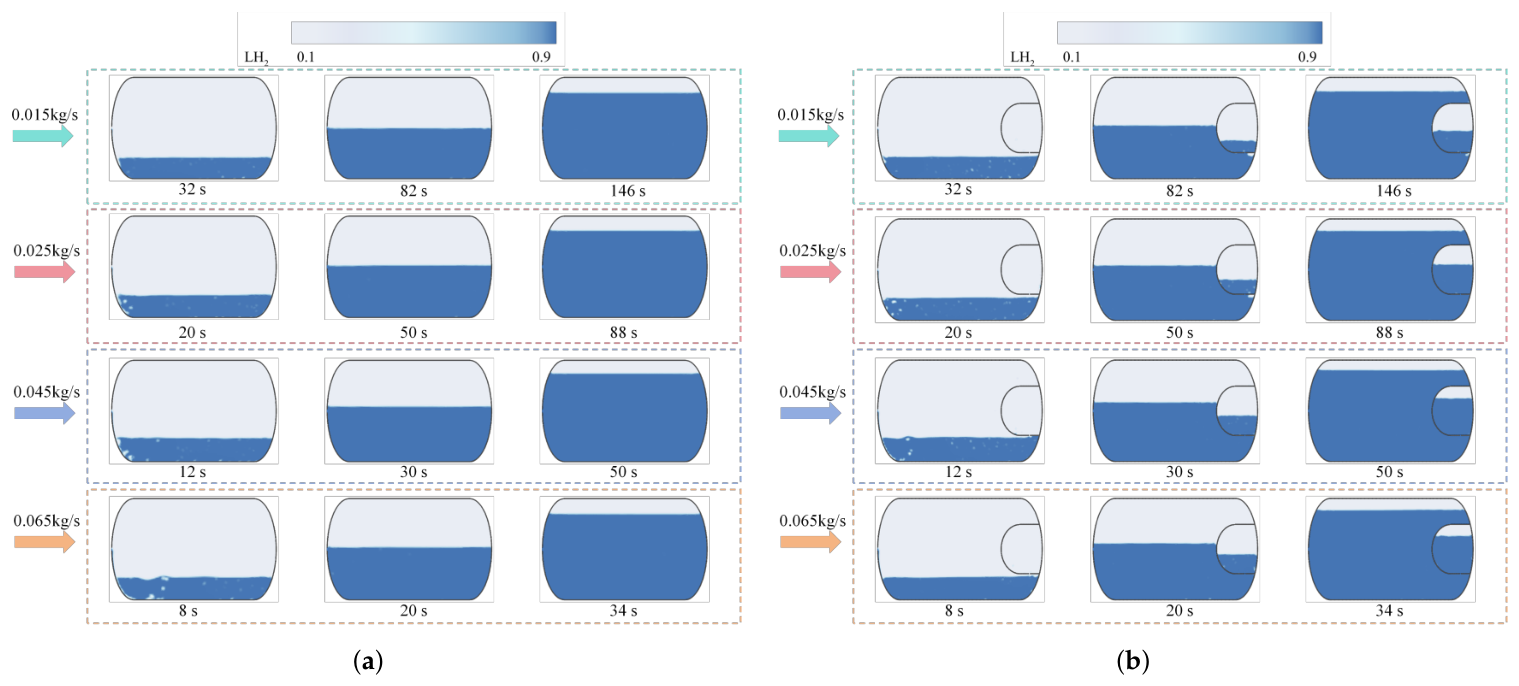
Figure 6 presents the phase distribution contours during the filling process of the liquid hydrogen cylinder under different filling rates. To compare the evolution of the gas–liquid interface at equivalent filling conditions, three representative liquid-level positions were selected, corresponding to the initial filling stage, the intermediate filling stage, and the near-overfilling stage, respectively. This comparison method avoids using identical physical times, because the total filling duration differs substantially among the cases with different inlet mass flow rates.
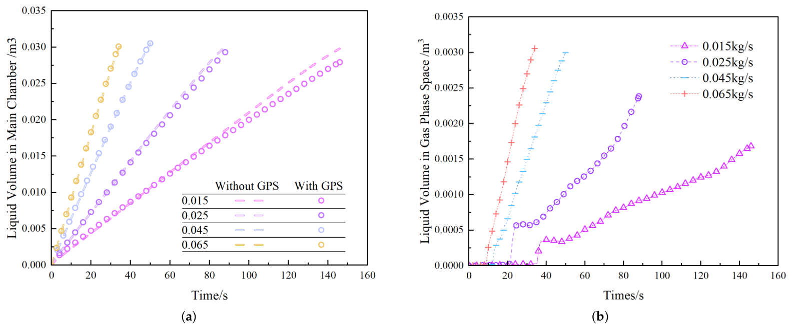
Figure 7 further shows the corresponding time histories of liquid hydrogen volume in the main chamber and gas-phase space. Four filling rates, namely 0.015 kg/s, 0.025 kg/s, 0.045 kg/s, and 0.065 kg/s, were considered to evaluate the influence of inlet flow rate on liquid accumulation, vapor retention, gas–liquid interface evolution, and the overfilling response of the cylinder.
After entering the cylinder, LH2 initially accumulates at the bottom of the main chamber under the combined effects of gravity and inlet momentum. A continuous liquid region is gradually established near the lower wall, whereas the upper part of the cylinder remains occupied by gaseous hydrogen. As filling proceeds, the liquid level rises continuously and the available vapor volume in the main chamber decreases. Accordingly, the gas–liquid interface moves upward, which is reflected in the phase contours by the gradual expansion of the liquid region and the corresponding reduction in the gas region.
At the beginning of filling, most of the injected LH2 remains in the main chamber, while the gas-phase space is still predominantly occupied by vapor. The gas-phase space is not immediately invaded by liquid because the liquid level must first rise to the connecting passage between the two regions. Once the liquid reaches this passage, part of the LH2 begins to enter the gas-phase space. Therefore, the increase in liquid volume within the gas-phase space is delayed relative to that in the main chamber. This behavior indicates that the main chamber receives LH2 first, whereas the gas-phase space acts as an additional safety volume that is occupied only during the later stage of filling.
At a filling rate of 0.015 kg/s, the inlet momentum is relatively weak. The liquid phase spreads gradually along the bottom of the main chamber, and the gas–liquid interface remains comparatively smooth and stable. No pronounced interface breakup, droplet entrainment, or gas entrainment is observed in the phase contours. The relatively small slope of the liquid volume curve in the main chamber also indicates a slow and steady accumulation process. Meanwhile, the liquid volume in the gas-phase space remains low for an extended period, suggesting that the vapor cushion is effectively preserved. Under this condition, the gas-phase space provides the strongest buffering effect because a substantial portion of its volume remains available for vapor compression. The relatively stable interface and gradual liquid-level rise also reduce the possibility of rapid vapor compression during the final filling stage.
When the filling rate increases to 0.025 kg/s, the liquid level in the main chamber rises more rapidly. The liquid region expands over a larger area at the same filling stage, and the liquid volume curve in the main chamber becomes steeper. Although the gas–liquid interface remains generally continuous, local fluctuations begin to appear near the liquid surface and the connecting passage. Compared with the 0.015 kg/s case, the liquid reaches the connecting region earlier and begins to enter the gas-phase space sooner. Consequently, the liquid volume in the gas-phase space starts to increase at an earlier time. However, a distinct vapor region is still retained in the upper part of the gas-phase space. This result indicates that the gas cushion has not yet been fully displaced by liquid hydrogen and that the gas-phase space still provides a measurable buffering capacity during the later filling period.
At 0.045 kg/s, the influence of inlet momentum becomes more pronounced. Liquid hydrogen occupies a large portion of the main chamber over a shorter filling time, and the gas–liquid interface exhibits stronger fluctuations. The enhanced liquid-jet momentum promotes local interface deformation and may induce liquid entrainment into the upper vapor region. As a result, the interface stability decreases compared with the lower filling rate cases. The liquid volume curves show that the main chamber fills rapidly, while the gas-phase space is also invaded by LH2 at a higher rate. Once the liquid level reaches the connecting passage, liquid enters the gas-phase space more easily, thereby reducing the volume available for vapor retention. Although part of the vapor remains in the gas-phase space, the remaining gas volume is substantially smaller than that under the 0.015 kg/s and 0.025 kg/s conditions. This behavior demonstrates that the buffering effect of the gas-phase space is progressively weakened as the filling rate increases.
At the highest filling rate of 0.065 kg/s, the filling process displays the strongest transient behavior. Liquid hydrogen enters the main chamber rapidly, and the liquid level rises within a very short period. The vapor region is compressed toward the upper part of the cylinder, while the gas–liquid interface becomes highly disturbed. The large inlet momentum intensifies interfacial oscillation and may result in localized droplet entrainment and gas entrainment. The liquid volume curve in the main chamber rises most rapidly under this condition, confirming that a high filling rate can substantially shorten the filling time. However, the gas-phase space is also occupied by liquid at a much faster rate. The residual vapor is compressed rapidly, and the effective volume available for pressure buffering decreases significantly. Although a small vapor region may still remain in the upper portion of the gas-phase space, its ability to accommodate further liquid displacement becomes limited. Therefore, the high-flow-rate condition presents the greatest potential risk of rapid vapor compression and pressure increase during the final filling stage.
Based on the phase contours and the time histories of liquid hydrogen volume in the main chamber and gas-phase space, the filling process can be divided into three characteristic stages: the main chamber-dominated filling stage, the coupled filling stage of the main chamber and gas-phase space, and the overfilling compression stage.
The first stage is the main chamber-dominated filling stage. After entering the cylinder, LH2 initially accumulates at the bottom of the main chamber under the action of gravity and gradually forms a continuous liquid region. At this stage, the liquid level in the main chamber remains relatively low, and the injected liquid has not yet reached the passage connecting the main chamber with the gas-phase space. Therefore, most of the incoming LH2 is retained in the main chamber. Accordingly, the liquid volume in the main chamber increases continuously, whereas that in the gas-phase space changes only slightly and remains predominantly occupied by gaseous hydrogen. Since the gas-phase space is not yet significantly invaded by liquid, a relatively large compressible vapor volume is preserved within the system, resulting in an evident gas cushion buffering effect.
The second stage is the coupled filling stage of the main chamber and gas-phase space. As the liquid level in the main chamber continues to rise, LH2 gradually approaches and reaches the connecting passage, after which part of the liquid begins to enter the gas-phase space. During this period, the liquid volumes in both regions increase simultaneously, indicating that the two chambers participate in the filling process concurrently. Compared with the first stage, the growth rate of liquid volume in the gas-phase space becomes more pronounced, showing that its original vapor volume is progressively occupied and compressed by the incoming liquid. In addition, gas–liquid interfacial disturbances near the connecting passage become stronger. The distribution of LH2 between the main chamber and gas-phase space is jointly influenced by the liquid level, inlet momentum, and local pressure variation. This stage represents the transition of the gas-phase space from a primarily vapor storage region to a vapor–liquid coexistence zone with a buffering function.
The third stage is the overfilling compression stage. When the liquid level in the main chamber continues to increase and LH2 progressively intrudes into the gas-phase space, the effective volume available for the residual vapor decreases rapidly. The remaining gas is therefore further compressed, and the occupation of the gas cushion volume by liquid becomes increasingly significant. As the compressible gas volume diminishes, the ability of the gas-phase space to buffer subsequent liquid inflow gradually weakens, making rapid compression and pressure rise more likely near the end of filling. With increasing filling rate, the liquid reaches the connecting passage and enters the gas-phase space earlier. Consequently, the onset of the third stage occurs sooner, the liquid intrusion rate becomes higher, and the available gas cushion volume decreases more rapidly. Therefore, although a higher filling rate can shorten the overall filling time, it also weakens the buffering effect of the gas-phase space during the final filling stage and increases the risk of rapid vapor compression under overfilling conditions.
From a safety perspective, the gas-phase space is not designed to completely prevent LH2 from entering the upper region of the cylinder. Its primary function is to delay the occupation of the gas cushion region and maintain a certain amount of compressible vapor during the late filling stage. At low filling rates, liquid hydrogen enters the gas-phase space slowly, allowing a larger vapor volume to be retained for a longer period. This condition provides a relatively stable pressure-buffering effect. At high filling rates, liquid hydrogen reaches and enters the gas-phase space more rapidly, causing the available gas volume to decrease quickly. Nevertheless, the additional space still prevents the vapor cushion from being displaced instantaneously and provides a limited pressure-buffering margin during overfilling.
Overall, the liquid volume variation in the main chamber mainly reflects the global filling rate, whereas the liquid volume change in the gas-phase space directly reflects the vapor retention capability of the gas-phase safety volume. By introducing this additional space, the internal liquid distribution pathway is modified. Instead of experiencing only direct vapor compression in the main chamber, the cylinder undergoes a coupled process involving main chamber filling, delayed liquid intrusion into the gas-phase space, and progressive vapor cushioning. This structural arrangement can improve the safety margin during the final filling stage. However, its effectiveness decreases as the filling rate increases. Therefore, the filling strategy should balance refueling efficiency against the vapor retention capacity of the gas-phase space, and excessively high filling rates should be avoided when the pressure-buffering capability is limited.
3.2. Pressure Variation Curves
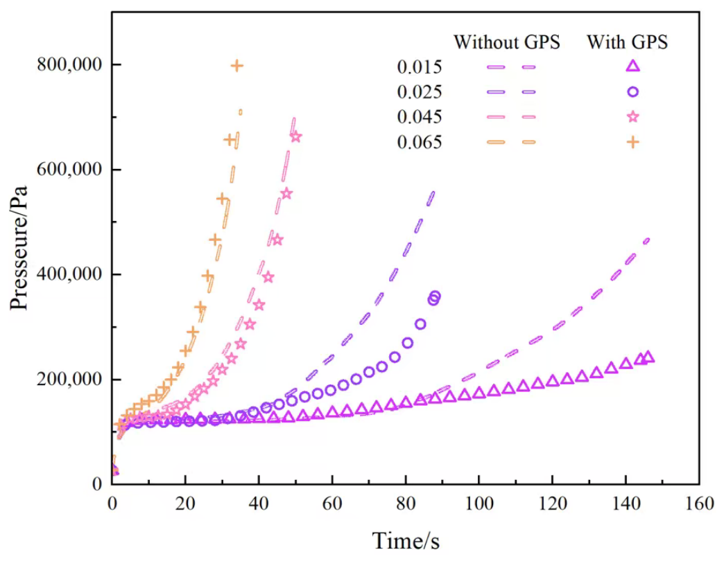
Figure 8 illustrates the temporal evolution of the internal pressure in the liquid hydrogen cylinder under different filling rates. Overall, the pressure response under all conditions exhibits three distinct stages: a rapid pressure increase at the beginning of filling, a relatively moderate growth period in the middle stage, and a second rapid increase near the end of filling. Although the duration of each stage, the pressure rise rate, and the final pressure level vary with the inlet mass flow rate, the general evolution pattern remains similar. This indicates that the pressure response during liquid hydrogen filling is not controlled by a single mechanism. Instead, it results from the combined effects of liquid hydrogen flash evaporation and evaporation, gaseous hydrogen condensation, gas–liquid interfacial disturbance, liquid volume redistribution, reduction in the residual vapor volume, and gas compression.
The pressure evolution is closely related to the phase distribution inside the cylinder and to the variation in liquid hydrogen volume within the main chamber and gas-phase space. At the initial stage, the thermal and mass transfer processes between the liquid and vapor phases are most intense. During the intermediate stage, liquid hydrogen gradually accumulates and forms a relatively stable liquid region, while gas cooling and local condensation become increasingly important. In the final stage, the effective volume available for the residual gas decreases substantially, and gas compression gradually becomes the dominant factor governing the rapid pressure increase. Therefore, the variation in the slope of the pressure curves reflects the change in the dominant heat transfer, mass transfer, and volume compression mechanisms during filling.
At the beginning of filling, the internal pressure rises rapidly within a short period. Once LH2 enters the cylinder through the inlet, it comes into direct contact with the original hydrogen vapor, the inner wall, and local regions with relatively high temperatures. Because the temperature of the incoming liquid hydrogen is extremely low, whereas the initial vapor and wall temperatures are comparatively higher, heat is transferred from the surrounding medium to the liquid hydrogen. Under this local thermal load, a fraction of the liquid hydrogen undergoes flash evaporation and evaporation. The phase transition from liquid to vapor increases the gas-phase mass rapidly, which directly causes the pressure inside the cylinder to rise.
The rapid pressure increase during the initial period is not caused solely by flash evaporation. It is also affected by the flow disturbance associated with the inlet jet. The incoming liquid hydrogen possesses a certain momentum, and a strongly mixed gas–liquid region may form near the inlet. At this time, a stable and continuous liquid layer has not yet developed at the bottom of the main chamber, and the gas–liquid interface is still evolving rapidly. Strong interfacial fluctuations increase the effective contact area between the liquid hydrogen and the gaseous hydrogen, thereby enhancing local heat transfer and phase change processes. The pronounced gas–liquid disturbance observed near the inlet in the phase contours further supports the existence of strong transient flow and phase change behavior in this region. Therefore, the rapid pressure rise at the beginning of filling can be attributed to the combined effects of flash evaporation, evaporation, and intense gas–liquid disturbance near the inlet.
As filling continues, liquid hydrogen gradually accumulates at the bottom of the main chamber and forms a more continuous liquid region. The overall shape of the gas–liquid interface becomes more stable, and the degree of local gas–liquid mixing decreases. At the same time, the extent of direct contact between the liquid hydrogen and the initially warm vapor or wall regions is reduced. The higher-temperature regions within the cylinder are progressively cooled by the continuously accumulated low-temperature liquid hydrogen. Consequently, the driving force for flash evaporation and evaporation decreases, and the amount of liquid transformed into vapor per unit time is reduced. As a result, the pressure rise rate gradually decreases.
During the intermediate filling stage, the pressure curve enters a relatively moderate growth period. At this stage, a stable liquid hydrogen accumulation region has been established at the bottom of the main chamber, and the liquid level continues to rise. However, the liquid has not yet occupied most of the available volume inside the cylinder. The cooling effect of the low-temperature liquid hydrogen on the surrounding vapor and the inner wall becomes increasingly significant, causing the gas-phase temperature to decrease. Gaseous hydrogen located near the low-temperature liquid surface may partially condense as the local temperature decreases. This condensation process reduces the gas-phase mass and thereby offsets part of the pressure increase caused by liquid evaporation.
Accordingly, the pressure evolution in the intermediate stage can be regarded as the result of competition among evaporation, condensation, and gas compression. On the one hand, liquid hydrogen continues to enter the cylinder, reducing the volume available for the gas phase and producing a certain degree of compression. On the other hand, the continued cooling of the vapor and wall promotes local condensation, which suppresses the increase in gas-phase mass. Because these mechanisms partially counteract each other, the pressure curve exhibits a relatively slow and stable upward trend during this period. The lower pressure rise rate indicates that the internal process has gradually changed from the strongly non-equilibrium state observed at the beginning of filling to a more stable vapor–liquid coexistence state.
As the filling process advances further, the liquid hydrogen volume continues to increase, and the effective volume occupied by the residual vapor in the main chamber decreases significantly. The pressure curve then enters a second rapid-rise stage. Unlike the initial stage, the dominant mechanism responsible for the rapid pressure increase at the end of filling is no longer the rapid growth of gas-phase mass caused by flash evaporation. Instead, the main reason is the strong compression of the remaining gas. As the liquid level rises continuously, the available gas volume in the upper part of the main chamber and in the gas-phase space decreases progressively. Under these conditions, even a relatively small additional increase in liquid hydrogen volume can lead to a substantial reduction in the residual gas volume and, consequently, a marked pressure increase.
The phase contours show that, during the late filling stage, the liquid phase occupies most of the main chamber, while gaseous hydrogen is confined mainly to the upper region of the main chamber or to local regions within the gas-phase space. Because the vapor is restricted to a limited volume, its pressure becomes more sensitive to further liquid-level changes. Once liquid hydrogen continues to rise and intrudes into the gas-phase space, the gas volume originally available for buffering is progressively occupied by liquid. The remaining gas is then subjected to stronger compression. As a result, the slope of the pressure curve increases significantly in the later stage. This behavior indicates that the cylinder has gradually entered the overfilling compression stage, during which the remaining buffering capacity of the gas-phase safety volume decreases rapidly.
A comparison of the pressure curves under different filling rates shows that, as the filling rate increases from 0.015 kg/s to 0.065 kg/s, the pressure curves shift progressively to the left. In other words, the time required to reach the same pressure level decreases substantially. This result is mainly because a higher filling rate introduces a larger amount of liquid hydrogen into the cylinder per unit time, leading to a faster rise in the liquid level and a more rapid reduction in the available gas volume. In addition, a higher inlet flow rate corresponds to a greater inlet momentum, which intensifies the disturbance of the gas–liquid interface and enhances the heat and mass transfer processes near the inlet. Consequently, the rapid pressure rise stage at the beginning of filling occurs earlier, the liquid reaches the gas-phase space sooner, and the final gas compression stage is initiated more rapidly.
For the cylinder configuration without a gas-phase space, gaseous hydrogen is mainly retained at the top of the main chamber, and no additional volume is available for gas buffering. Under low filling rates, a certain amount of vapor can still remain in the upper part of the main chamber, and the pressure increase is relatively moderate. However, under high filling rates, the liquid level rises rapidly and the gas cushion volume at the top of the main chamber decreases within a short period. The residual gas is then strongly compressed, resulting in a more pronounced pressure increase near the end of filling. In this configuration, the gas in the main chamber must simultaneously accommodate the pressure regulation associated with vapor–liquid phase transition and the direct displacement caused by the rising liquid level, which limits the overall pressure-buffering capability.
By contrast, the configuration incorporating a gas-phase space can improve the pressure response during the late filling stage to a certain extent. The gas-phase space is not designed to completely prevent liquid hydrogen from entering. Instead, it provides an additional volume that delays the occupation of the gas cushion region by liquid hydrogen. At low and moderate filling rates, once the liquid level in the main chamber reaches the connecting passage, part of the liquid enters the gas-phase space, but a certain volume of gaseous hydrogen can still be retained. This retained vapor acts as an additional gas cushion and provides volumetric buffering for subsequent liquid inflow. Therefore, compared with the structure without a gas-phase space, the overall pressure level is lower and the pressure rise process is relatively smoother.
At low filling rates, liquid hydrogen enters the gas-phase space slowly, allowing the gas-phase space to retain a relatively large vapor volume for a longer period. Under this condition, the buffering effect of the gas-phase space is most evident and can effectively delay the rapid pressure increase near the end of filling. At moderate filling rates, the liquid enters the gas-phase space earlier, but part of the vapor volume is still retained. Therefore, the gas-phase space continues to provide a certain pressure-buffering effect. In this case, pressure regulation inside the cylinder no longer depends only on the compression of the gas at the top of the main chamber; instead, both the main chamber and the gas-phase space participate in the accommodation of the residual vapor volume.
However, when the filling rate increases to 0.045 kg/s and 0.065 kg/s, the buffering effect of the gas-phase space is significantly weakened. Under high-flow-rate conditions, the liquid level in the main chamber rises rapidly, and liquid hydrogen reaches the connecting passage earlier and enters the gas-phase space at a higher rate. Because the liquid intrusion rate is high, the gas volume originally retained for buffering in the gas-phase space is occupied rapidly, and the remaining vapor is strongly compressed. Although a local vapor region may still remain in the gas-phase space, its effective buffering capacity is substantially reduced. Therefore, under high filling rates, the gas-phase space can still delay the complete displacement of the gas cushion to some extent, but its ability to suppress the rapid pressure rise during the final stage is limited.
By combining the pressure curves, phase contours, and liquid hydrogen volume histories, a clear correspondence among these results can be identified. The rapid pressure increase in the initial stage corresponds mainly to liquid hydrogen flash evaporation, evaporation, and strong gas–liquid disturbance near the inlet. The slower pressure increase in the intermediate stage corresponds to the gradual stabilization of liquid accumulation in the main chamber, enhanced cooling of the vapor and wall by liquid hydrogen, and the occurrence of local condensation. The second rapid pressure increase in the final stage corresponds primarily to the strong compression of the residual gas after the available vapor volume in the main chamber and gas-phase space has decreased significantly. The liquid volume curves reflect the redistribution of liquid hydrogen between the main chamber and gas-phase space, whereas the phase contours provide a direct visualization of gas–liquid interface movement and vapor-volume compression. Together, these results explain the physical mechanisms responsible for the pressure evolution at different filling stages.
From an engineering perspective, the filling strategy for liquid hydrogen cylinders should balance refueling efficiency and pressure safety. A high filling rate can shorten the total filling time and improve refueling efficiency; however, it also intensifies gas–liquid disturbance near the inlet, accelerates liquid accumulation in both the main chamber and gas-phase space, and causes the overfilling compression stage to occur earlier. A lower filling rate prolongs the total filling time but helps maintain a more stable gas–liquid interface, preserve a larger gas cushion volume, and reduce the pressure rise rate. Therefore, the filling rate should be selected according to the cylinder geometry, gas-phase space volume, initial pressure condition, allowable operating pressure, and the pressure-control capability of the refueling system. When the pressure-buffering capacity is limited, excessively high filling rates should be avoided. In particular, reducing the filling rate during the final stage may help mitigate the pressure risk associated with rapid compression of the remaining vapor.
3.3. Temperature Variation
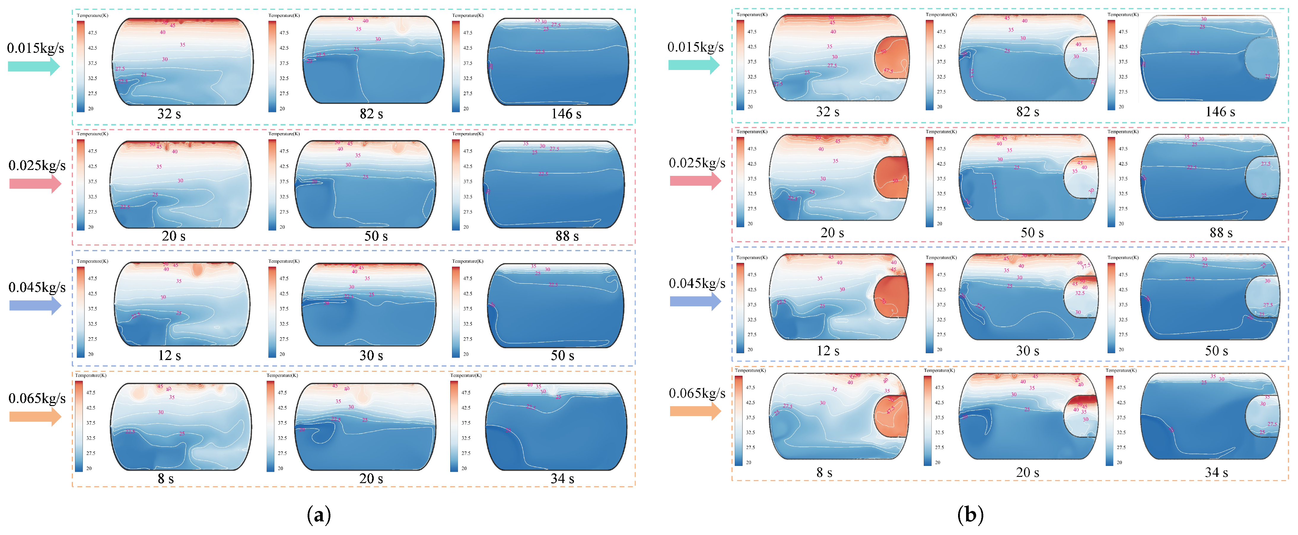
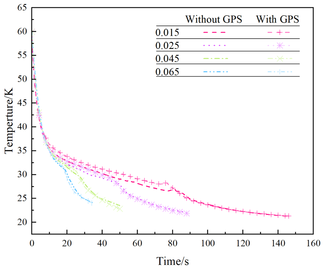
Figure 9 and
Figure 10 show the temperature contours inside the tank and the corresponding temperature histories under different filling rates, respectively. When combined with the phase contours discussed above, the temperature field generally exhibits a rapid decrease at the beginning of filling, followed by a more gradual decline, and finally approaches the temperature range of liquid hydrogen. This evolution is closely associated with the cooling effect of incoming LH
2, vapor–liquid phase change, wall heat transfer, and the redistribution of liquid and vapor volumes inside the cylinder. In particular, the temperature response is strongly influenced by the movement of the gas–liquid interface and the gradual occupation of the main chamber and gas-phase space by liquid hydrogen.
During the initial filling stage, the temperature inside the cylinder decreases most rapidly. At this time, low-temperature liquid hydrogen enters a tank that is initially at a relatively higher temperature and exchanges heat intensely with the gaseous hydrogen and the inner wall. The phase contours indicate that LH2 first forms a low-temperature liquid region at the bottom of the main chamber and comes into direct contact with the upper vapor phase. Owing to the large initial temperature difference between the vapor, wall, and liquid hydrogen, the thermal driving force is high. Consequently, heat is transferred rapidly from the warmer gas phase and wall to the incoming liquid hydrogen, causing a sharp decline in the local and average tank temperatures.
Although part of the incoming liquid hydrogen undergoes flash evaporation during this stage and contributes to the rapid pressure rise, the overall thermal effect remains dominated by the strong cooling capacity of LH2. In other words, the energy absorbed by liquid hydrogen from the wall and surrounding gas is sufficiently large to reduce the temperature of the system rapidly. The temperature contours generally show a cold liquid region expanding upward from the bottom of the main chamber, while a relatively warm vapor region remains in the upper part of the cylinder. This temperature stratification is particularly evident at the beginning of filling because the lower liquid region is cooled immediately, whereas the upper vapor region requires a longer time to exchange heat with the liquid phase.
The initial temperature decrease is also influenced by inlet-induced flow disturbance. Liquid hydrogen enters the cylinder with a certain momentum, producing local mixing near the inlet and increasing the contact area between the cold liquid and the warmer vapor. This enhanced gas–liquid contact promotes convective heat transfer and accelerates the cooling of the vapor phase near the injection region. However, the cooling effect is not spatially uniform. Regions close to the liquid pool and inlet cool more rapidly, whereas the upper vapor region and wall sections farther from the liquid phase retain relatively higher temperatures for a longer period. Therefore, the temperature field in the early stage is characterized by a strong vertical gradient.
As filling proceeds, the rate of temperature decrease gradually becomes lower. The liquid volume in the main chamber continues to increase, and the gas–liquid interface becomes more stable. Most regions of the tank have already been exposed to the cooling effect of liquid hydrogen, and the temperature difference between the vapor phase, wall, and liquid gradually decreases. As a result, the heat transfer driving force weakens. The temperature curve therefore changes from a steep decline in the initial stage to a slower decrease during the intermediate stage.
In the temperature contours, this process is reflected by the continuous expansion of the low-temperature liquid region and the gradual shrinkage of the upper high-temperature vapor region. However, the high-temperature gas region does not disappear immediately, indicating that cooling of the vapor phase has a certain delay. This delay is related to the relatively low thermal conductivity and limited convective mixing of the gaseous hydrogen, especially in the upper part of the tank. In addition, the wall temperature cannot decrease instantaneously because the wall has thermal inertia. Even after the nearby fluid has been cooled, heat stored in the wall may continue to transfer into the vapor and liquid regions. Therefore, the middle stage represents a coupled cooling process involving liquid accumulation, vapor cooling, wall heat release, and gradual reduction in thermal stratification.
The comparison among different filling rates shows that a higher filling rate produces a faster temperature decrease and shortens the time required for the tank to enter the low-temperature range. Under the 0.045 kg/s and 0.065 kg/s conditions, liquid hydrogen fills the main chamber within a shorter period, and the low-temperature liquid phase occupies a larger volume more rapidly. Consequently, the cooling effect on the vapor phase and wall is intensified, and the temperature curves decrease more sharply. The rapid upward movement of the liquid level also reduces the volume of warm vapor remaining in the main chamber, thereby accelerating the overall cooling process.
Under the 0.015 kg/s condition, liquid hydrogen enters more slowly, and the cooling process lasts longer. The liquid level rises gradually, and the upper vapor region remains exposed to relatively higher temperatures for an extended period. Therefore, the temperature decrease is more moderate, and the thermal stratification inside the cylinder persists for a longer time. This trend is consistent with the liquid-level movement observed in the phase contours. Under high filling rates, the liquid phase expands more rapidly and the gas phase is compressed at a higher rate; under low filling rates, the gas–liquid interface advances more slowly and the cooling process is correspondingly milder.
Comparison between the structures with and without a gas-phase space further indicates that the gas-phase space modifies the temperature decrease process inside the cylinder. At a low filling rate, the structure with a gas-phase space generally exhibits a slightly higher overall temperature and a slower cooling rate. This is because the gas-phase space remains mainly occupied by vapor during the early filling stage and forms a local region in which relatively warm gas is retained. Since LH2 does not immediately enter this space, the retained vapor and adjacent wall cannot be cooled as rapidly as the lower main chamber region.
Therefore, while the gas-phase space provides a safety gas cushion, it also introduces a local thermal-buffering effect. The temperature contours show a stratified distribution inside this region, with relatively warm gas remaining in the upper part and lower-temperature liquid occupying the lower part. This thermal delay is beneficial for retaining the gas cushion during low-speed filling, but it also means that the gas-phase space may remain thermally non-uniform for a longer period. The local temperature difference between the retained vapor and the adjacent liquid can influence condensation behavior and pressure evolution during the subsequent filling process.
At higher filling rates, the temperature of the structure with a gas-phase space decreases more rapidly. Once the liquid level in the main chamber rises quickly, liquid hydrogen reaches the connecting passage earlier and enters the gas-phase space sooner. This increases gas–liquid contact and enhances convective cooling inside the gas-phase space. The originally retained warm vapor is then compressed, cooled, and partially replaced by low-temperature liquid hydrogen. As a result, the temperature curve exhibits a more pronounced decrease. However, this rapid cooling also indicates that liquid hydrogen enters the gas-phase space earlier, meaning that the available gas-buffering volume decreases as the filling rate increases.
It should be noted that a lower tank temperature does not necessarily imply a lower pressure risk. During the early stage, the temperature decreases rapidly because LH2 absorbs heat from the warmer gas and wall, whereas flash evaporation may simultaneously increase the gas-phase mass and cause a rapid pressure rise. During the intermediate stage, the temperature continues to decrease more slowly, while gas cooling and local condensation partially restrain the pressure increase. In the final stage, the temperature gradually approaches the liquid hydrogen temperature range, but the remaining vapor volume is compressed strongly by the rising liquid level, which may cause the pressure to increase rapidly again. Therefore, the temperature response and pressure response should be interpreted together rather than separately.
In summary, the temperature variation curves correspond well with the phase contours and pressure curves. In the initial stage, strong contact between incoming LH2 and the warmer vapor and wall causes a rapid temperature decrease, while flash evaporation leads to a rapid pressure increase. In the intermediate stage, the liquid phase accumulates steadily, the vapor phase is progressively cooled, the wall releases stored heat gradually, and the temperature decrease becomes slower. In the final stage, the tank temperature approaches the liquid hydrogen temperature range, but the remaining gas volume is compressed, causing the pressure to rise rapidly again. Therefore, a high filling rate can improve cooling efficiency and reduce the time required for the tank to reach a low-temperature state, but it also accelerates the occupation and compression of the gas-phase space. A low filling rate is beneficial for maintaining the gas cushion and reducing the intensity of gas–liquid disturbance, although the cooling process becomes longer. The gas-phase space exhibits favorable thermal-buffering and gas retention effects under low-speed filling, whereas its buffering capability is weakened when liquid hydrogen enters rapidly under high-speed filling. Consequently, the selection of filling rate should consider both cooling performance and pressure-control requirements to ensure safe and stable liquid hydrogen filling.
4. Conclusions
In this study, a 34 L vehicle-mounted liquid hydrogen cylinder was investigated by using a non-isothermal two-dimensional numerical model that considered vapor–liquid two-phase flow, heat transfer, and phase change. The Volume of Fluid (VOF) method was employed to track the evolution of the gas–liquid interface, while the Lee phase change model was used to describe evaporation and condensation between liquid hydrogen and gaseous hydrogen. The filling behaviors of cylinders with and without a gas-phase safety space were compared under four filling rates of 0.015 kg/s, 0.025 kg/s, 0.045 kg/s, and 0.065 kg/s. The results reveal the coupled effects of liquid accumulation, gas retention, phase evolution, pressure rise, and temperature reduction during the liquid hydrogen filling process. The main conclusions are summarized as follows:
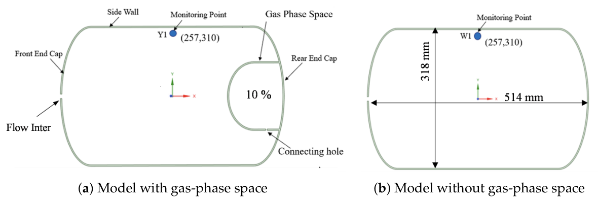
(1) The gas-phase safety space modifies the liquid hydrogen distribution path during the late filling stage and provides an additional vapor retention volume. For the cylinder with a gas-phase space, the safety volume accounts for 10% of the total effective cylinder volume, corresponding to 3.4 L. During filling, liquid hydrogen first accumulates in the main chamber and gradually forms a continuous liquid region near the bottom of the cylinder. The gas-phase safety space is not immediately occupied by liquid hydrogen. Instead, liquid hydrogen enters this region only after the liquid level in the main chamber rises to the connecting passage. Therefore, the gas-phase safety space behaves as a delayed filling region and retains a certain amount of compressible vapor during the early and intermediate filling stages. This structural feature delays the direct occupation of the gas cushion region by liquid hydrogen and changes the overfilling process from direct gas compression in the main chamber to a coupled process involving main chamber filling, delayed liquid intrusion, and vapor buffering in the gas-phase space.
(2) The filling rate significantly affects liquid-level rise, liquid distribution, and the vapor retention capability of the gas-phase safety space. When the filling rate increases from 0.015 kg/s to 0.065 kg/s, the time required for liquid hydrogen to reach the near-overfilling characteristic liquid level decreases from 146 s to 34 s, corresponding to a reduction of approximately 76.7%. This result confirms that increasing the inlet mass flow rate can substantially improve filling efficiency. However, the higher filling rate also increases the inlet momentum, accelerates gas–liquid interface disturbance, and causes liquid hydrogen to reach the connecting passage earlier. Consequently, liquid hydrogen enters the gas-phase safety space sooner, and the remaining compressible vapor volume decreases more rapidly. Under low filling rates, the gas-phase space can retain a relatively large gas volume for a longer period. In contrast, under high filling rates, the safety space is invaded by liquid more rapidly, and its pressure-buffering capacity is progressively weakened.
(3) The internal pressure response during filling exhibits three characteristic stages: an initial rapid rise, a relatively slow increase during the intermediate period, and a second rapid rise near the end of filling. The initial pressure increase is mainly associated with liquid hydrogen flash evaporation, evaporation, and strong gas–liquid disturbance near the inlet. During the intermediate stage, liquid hydrogen gradually accumulates in the main chamber, while the low-temperature liquid phase cools the vapor and wall. The reduction in flash evaporation intensity and the occurrence of local vapor condensation partially offset the pressure increase caused by continuous liquid inflow. As a result, the pressure rise becomes relatively moderate. In the final stage, the available vapor volume in the main chamber and gas-phase space decreases significantly, and compression of the residual gas becomes the dominant mechanism responsible for the renewed rapid pressure increase.
(4) Compared with the cylinder without a gas-phase safety space, the structure incorporating a gas-phase space can retain additional compressible vapor during low- and medium-rate filling processes. This additional vapor volume reduces the rate at which the gas cushion is compressed and delays the occurrence of rapid pressure rise during the final filling stage. Therefore, the gas-phase safety space improves the pressure-buffering capability and provides a larger safety margin under relatively moderate filling conditions. However, when the filling rate reaches 0.045 kg/s and 0.065 kg/s, liquid hydrogen enters the gas-phase space earlier and compresses the retained vapor more rapidly. Under these conditions, the gas-phase safety space still delays complete vapor displacement to a certain extent, but its ability to suppress the final pressure rise becomes limited. This indicates that the safety benefit provided by the gas-phase space is strongly dependent on the selected filling rate.
(5) The temperature evolution is closely coupled with phase distribution and pressure response. In the initial stage, incoming low-temperature liquid hydrogen absorbs heat rapidly from the warmer vapor and wall, resulting in a sharp decrease in the tank temperature. Although flash evaporation may simultaneously increase the gas-phase mass and cause a rapid pressure rise, the overall thermal effect is dominated by the strong cooling capability of liquid hydrogen. During the intermediate stage, the low-temperature liquid region expands continuously, the gas–liquid interface becomes more stable, and the temperature reduction rate gradually decreases as the thermal driving force weakens. In the final stage, the tank temperature gradually approaches the liquid hydrogen temperature range; however, the remaining vapor volume is strongly compressed by the rising liquid level. Therefore, a lower tank temperature does not necessarily correspond to a lower pressure risk, particularly during the late filling stage.
(6) From an engineering perspective, the gas-phase safety space provides both thermal-buffering and vapor retention functions under low-speed filling conditions. It can maintain a certain amount of gas cushion, delay the occupation of the upper vapor region by liquid hydrogen, and reduce the sensitivity of pressure rise to further liquid inflow. Nevertheless, high filling rates improve cooling efficiency and shorten the filling time at the expense of faster vapor compression and reduced pressure-buffering capability. Therefore, the filling strategy for vehicle-mounted liquid hydrogen cylinders should balance refueling efficiency, cooling performance, available gas cushion volume, and pressure safety. In practical applications, an excessively high filling rate should be avoided when the pressure-buffering capacity is limited. A lower or controlled filling rate during the late filling stage may be beneficial for mitigating the risk of rapid pressure rise and improving the safety margin against overfilling.