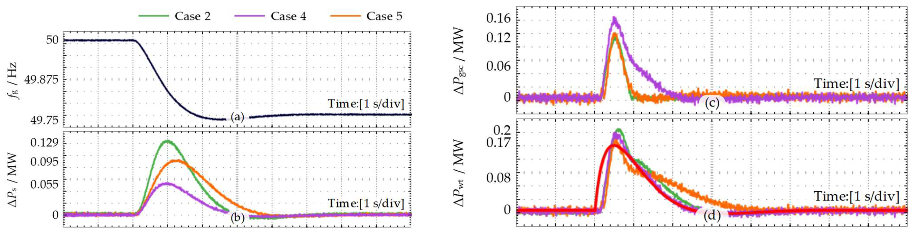
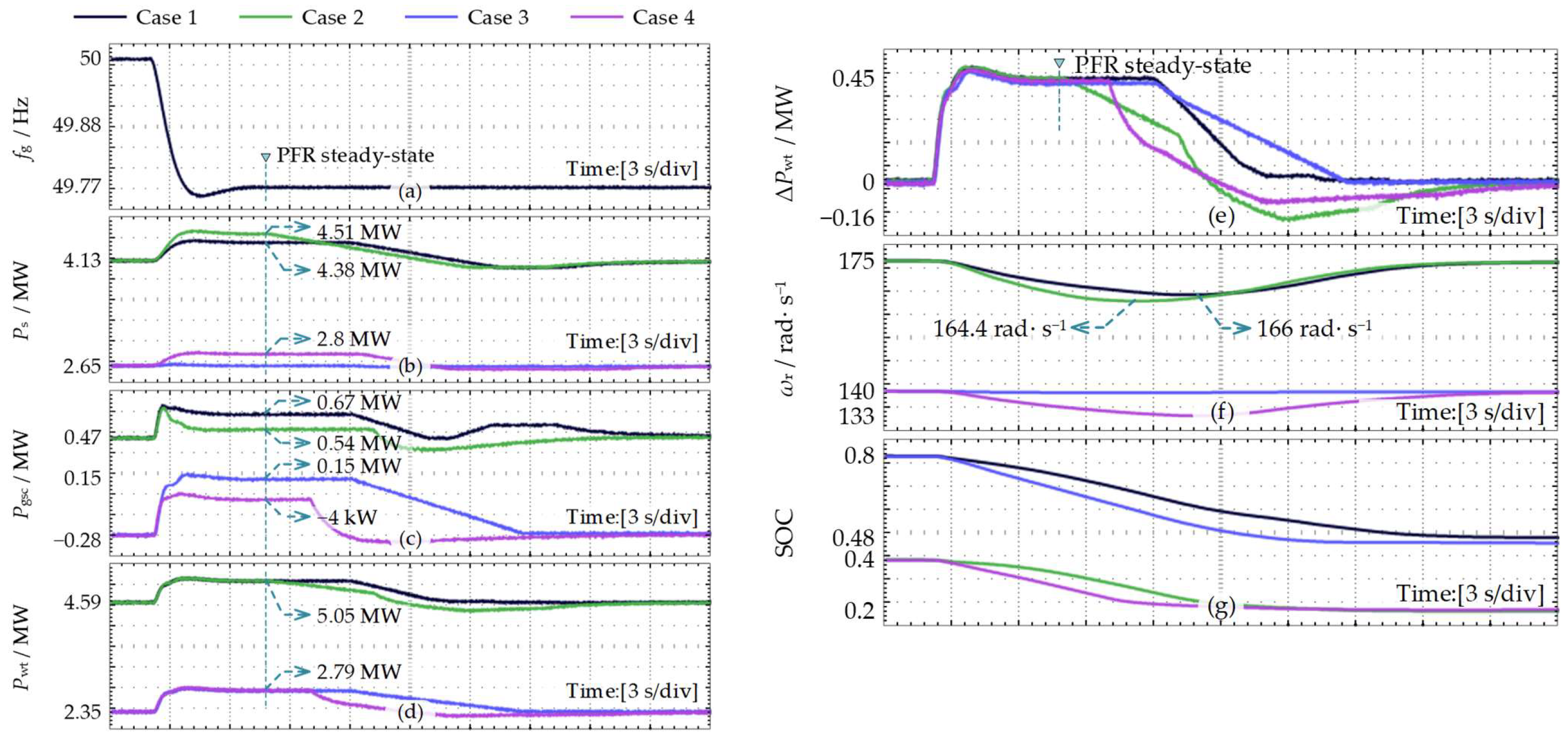
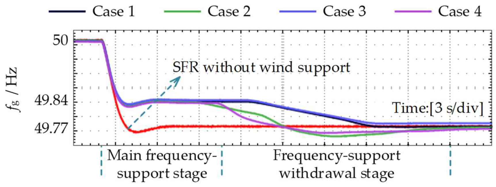
1. Introduction
Driven by the global transition toward low-carbon power systems, the penetration of renewable energy sources such as wind and photovoltaic power continues to increase, and power systems are shifting from synchronous-generator-dominated structures to power-electronic-interfaced sources [
1]. Synchronous generators naturally participate in frequency dynamics through rotor kinetic energy, power-angle characteristics, and governor systems. In contrast, the active-power response of converter-interfaced renewable energy units is mainly determined by control strategies and is therefore decoupled from grid-frequency dynamics [
2]. As renewable penetration increases, system equivalent inertia and frequency-regulation capability decrease, leading to a higher rate of change in frequency, a lower frequency nadir, and increased frequency-security risks [
3]. Existing control strategies have enabled wind turbines to provide active frequency support. However, the available support power is governed by wind speed, rotor speed, and converter power margin, causing the frequency-support response to vary across operating conditions. Achieving controllable and stable frequency support over a wide operating range has therefore become a central requirement for renewable energy units [
4].
Wind-turbine frequency support is implemented by regulating active power to improve the post-disturbance system power balance and suppress frequency deviations. In conventional doubly fed induction generator (DFIG) wind turbines, the power reserve available for frequency support mainly comes from rotor kinetic energy and is released through rotor-side converter (RSC) control. The active power of the grid-side converter (GSC) is constrained by the DC-link power balance and therefore cannot provide independently controlled active-power regulation for frequency support [
5,
6]. When an energy-storage unit is connected to the DC link of the back-to-back converter, the GSC side obtains an adjustable power source. The energy-storage DFIG therefore forms dual power reserves consisting of rotor kinetic energy and DC energy storage. Since the wind-turbine power output is not naturally coupled with grid frequency, frequency-support strategies are required to release these two power reserves and form a controllable frequency-support power response.
Existing studies have developed several frequency-support strategies for DFIGs, including virtual synchronous generator (VSG) control, droop control, overspeed deloading, pitch-angle regulation, and energy-storage-assisted frequency regulation. VSG, virtual-inertia, and droop-control methods can introduce frequency-dependent active-power regulation based on the rate of change in frequency or frequency deviation, thereby improving the frequency response after disturbances; however, their power dynamics are affected by frequency measurement, power-reference generation, and the underlying converter control loops [
7]. Overspeed deloading and pitch-angle regulation can reserve active-power headroom for primary frequency regulation (PFR), but this is usually achieved at the cost of wind-energy capture efficiency or increased mechanical regulation burden [
8]. Energy-storage-assisted frequency regulation increases the available support power of wind turbines, while its effectiveness depends on storage state, power allocation, and converter execution capability [
9,
10]. These methods enable DFIGs to participate in frequency support, but the relationship among the target frequency-support power response, the VSG closed-loop power response, and the internal multi-channel power output remains insufficiently characterized.
Research on the frequency-support process has further considered power coordination, stability enhancement, support withdrawal, and rotor-speed recovery. Wind-storage coordinated PFR strategies have been developed to account for rotor kinetic-energy recovery, in which inertial and droop power are adaptively allocated on the DFIG side, and hybrid battery–supercapacitor power sharing is adopted on the storage side [
11]. For grid-forming DFIGs under VSG control, transient damping enhancement and steady-state recovery initial values have been introduced to suppress low-frequency oscillations and improve transient support performance [
12]. Adaptive rotor-speed recovery based on variable-coefficient PI control has been used to balance secondary frequency-drop suppression and rotor-speed recovery through staged active-power deloading [
13]. From the perspective of transient synchronization stability, PLL parameter design has been investigated by considering the opposite requirements of inertia enhancement and synchronization stability [
14]. Two-stage frequency-regulation strategies have further combined adaptive inertia and droop coefficients during the support stage with optimized switching and fuzzy PI control during the recovery stage [
15]. These studies improve DFIG frequency-response performance in terms of support dynamics, stability, and recovery, but they mainly focus on single-channel support, external wind-storage coordination, or post-support recovery. The power-response equivalence and wind-turbine-level coordinated configuration of internal RSC/GSC dual-VSG channels in energy-storage DFIGs remain insufficiently studied.
To address operating-condition variations, limited power margins, and multi-resource coordination, optimization algorithms have been applied to frequency-support parameter tuning, power allocation, and capability-boundary evaluation in DFIGs and wind-storage systems. Multi-objective particle swarm optimization has configured virtual inertia in DFIG wind farms using frequency nadir and time to nadir as objectives [
16]. Fuzzy logic control combined with model predictive control (MPC) has been used for wind-storage coordinated frequency regulation, where fuzzy logic adjusts support and droop coefficients, and MPC optimizes reference power allocation [
17]. For grid-forming DFIGs, bi-level MPC optimizes VSG coefficients and additional power commands at the upper level and improves stator voltage and current tracking at the lower level [
18]. Power-support capability models with coupled constraints of rotor speed, pitch angle, and rotor current allocate wind-farm frequency-control power according to turbine-level support capability [
19]. Knowledge- and data-driven Koopman-MILP methods transform nonlinear DFIG wind-farm frequency-support dynamics into high-dimensional linear models for online capability-boundary assessment [
20]. These studies improve the adaptability and security of frequency support, but mainly target system frequency indices, control-coefficient tuning, wind-storage power allocation, or capability boundaries. A systematic method is still needed to link the target inertial-support power response with the VSG closed-loop power response and to coordinate inertia-target decomposition with PFR power allocation in internal dual-VSG channels.
In summary, controllable and stable frequency support of energy-storage DFIGs requires a clear relationship between the equivalent inertia target and the VSG closed-loop power response, as well as dual-channel task allocation under operating-state constraints. Specifically, the equivalent inertia target is translated into a target inertial-support power response for VSG parameter configuration, while rotor speed, SOC, and GSC upward power margin determine the stator-side and GSC-side support contributions under a unified turbine power base. Based on this analysis, this paper proposes a power-response-equivalence-based dual-VSG method for energy-storage DFIGs, integrating VSG parameter configuration with dual-channel frequency-support task allocation.
Table 1 summarizes the key differences between representative existing methods and the proposed method.
The main contributions are as follows:
- (1)
A dual-VSG frequency-support power-response model of the energy-storage DFIG is established. The model reveals the frequency-disturbance-to-power-response relationships of the RSC-VSG and GSC-VSG channels, providing a theoretical basis for unified wind-turbine-level power-response characterization.
- (2)
A target-power-response-equivalence-based VSG inertia parameter configuration method is proposed. The method establishes a direct relationship between the equivalent inertia target and the VSG control parameter configuration, enabling the VSG closed-loop power response to match the target inertial-support response.
- (3)
A dual-VSG coordinated frequency-support allocation method considering operating-state constraints is proposed. It relates the wind-turbine-level frequency-support target to stator/GSC channel contributions, enabling stable and consistent support performance across different rotor-speed, SOC, and GSC power-margin conditions.
The remainder of this paper is organized as follows.
Section 2 presents the energy-storage DFIG model and dual-VSG control.
Section 3 and
Section 4 develop the power-response-equivalence-based parameter configuration and coordinated frequency-support strategy, respectively.
Section 5 provides HIL validation, and
Section 6 concludes the paper.
2. Modeling of Energy-Storage DFIG Wind Turbines for Frequency-Support Analysis
The energy-storage DFIG wind turbine extends the active-power control flexibility of the GSC through DC-link energy storage, thereby expanding the GSC control objective from solely maintaining DC-link voltage stability to active-power control with frequency-support capability. Based on this configuration, the RSC/GSC dual-VSGs enable both the stator-side active power and the GSC grid-connected power to respond to system frequency disturbances, thereby enhancing the overall equivalent inertia and PFR support capability of the turbine.
2.1. Topology and Power-Coupling Characteristics of Energy-Storage DFIG Wind Turbines
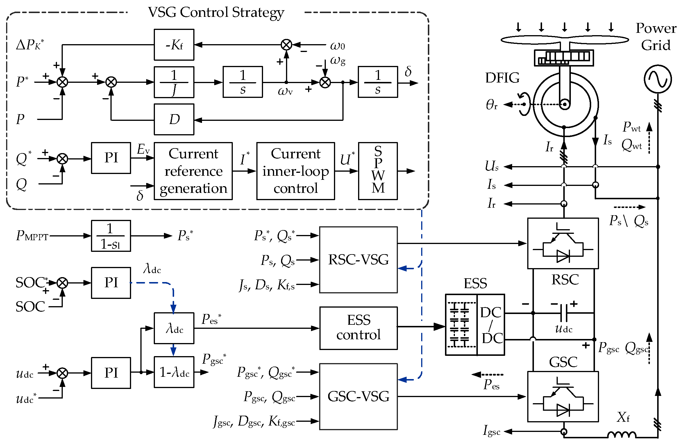
The structure of the energy-storage DFIG wind turbine and its control system is shown in
Figure 1. A supercapacitor energy-storage unit is connected to the DC bus of the back-to-back converter through a bidirectional DC/DC converter.
The power balance of the converter DC bus is expressed as
where
Cdc and
udc denote the DC-bus capacitance and DC-bus voltage, respectively;
Pr is the power injected into the DC bus from the rotor through the RSC;
Pes is the power absorbed by the energy-storage unit from the DC bus; and
Pgsc is the active power delivered from the GSC to the grid. When the DC-bus voltage is regulated to be stable, Equation (1) can be simplified as
This equation indicates that the energy-storage unit supplies the power difference between the GSC grid-connected power and the rotor-side power, thereby supporting independent GSC power control under stable DC-bus voltage conditions. Since the DC-bus voltage loop of the energy-storage DC/DC converter is designed with a higher bandwidth than the RSC and GSC power-control loops, the DC-bus power imbalance is regulated on a faster time scale. This reduces the dynamic coupling between the RSC-VSG and GSC-VSG through the DC bus during frequency-support operation.
The output power of the wind turbine is given by
where
Ps is the active power delivered from the stator to the grid. During frequency-support operation, the stator side provides frequency-regulation power by releasing rotor kinetic energy, whereas the GSC provides frequency-regulation power by utilizing the DC-side energy storage. Together, these two power components constitute the overall frequency-support output of the turbine.
Neglecting losses, the stator and rotor powers satisfy the following relationship with the slip
sl:
Substituting (4) into (2) yields
Therefore, the control of the energy-storage DFIG wind turbine power Pwt is essentially realized through the coordination of the stator power, the GSC power, and the energy-storage power.
2.2. RSC/GSC Dual-VSG Control Strategy
To accommodate the control characteristics of the energy-storage DFIG, in which the stator-side active power and the GSC grid-connected power can be independently regulated, RSC/GSC dual-VSGs are adopted to realize inertial support and frequency-regulation operation on both the stator side and the GSC side. The RSC-side VSG acts on stator active-power control, whereas the GSC-side VSG acts on the active-power control of the grid-side converter. The two VSGs adopt a unified power outer-loop structure. However, considering the differences in the electromagnetic channels and power bases corresponding to the RSC side and the GSC side, the VSG parameters should be configured separately.
In the power outer loop, the active-power loop generates the virtual angular frequency and phase angle based on the virtual rotor motion equation, whereas the reactive-power loop generates the magnitude of the virtual internal electromotive force according to the reactive-power deviation. Thus, a virtual internal electromotive force is formed to characterize the internal voltage characteristics of the equivalent synchronous machine. The main difference between the two control schemes lies in the dq-coordinate transformation angle aligned with the virtual internal electromotive force. The GSC-side VSG uses the phase angle of the virtual internal electromotive force, whereas the RSC-side VSG uses the slip angle between the phase angle of the virtual internal electromotive force and the rotor electrical angle.
Around a steady-state operating point, the small-signal active-power outer loop model of the VSG strategy is constructed based on the virtual rotor motion equation as follows:
where Δ denotes the small-signal increment of the corresponding variable;
J and
D are the virtual inertia and virtual damping parameters, respectively;
ωv and
θv are the virtual angular frequency and phase angle of the VSG, respectively;
ωg is the grid angular frequency;
P* and
P are the active-power command and the actual active power of the corresponding channel, respectively. When applied to the RSC side,
P =
Ps, with the corresponding parameters denoted as
Js and
Ds. When applied to the GSC side,
P =
Pgsc, with the corresponding parameters denoted as
Jgsc and
Dgsc.
The small-signal reactive-power loop of the VSG strategy can be expressed as
where
Ev is the magnitude of the virtual internal electromotive force of the VSG, and
GQ,PI(
s) is the transfer function of the reactive-power PI controller.
To analyze the relationship between the VSG equivalent inertia and the frequency-support power response, the power angle is defined as
The active and reactive powers of the VSG can be expressed as
where
Ug is the grid-voltage magnitude, and
Xeq is the equivalent reactance between the virtual internal electromotive force and the grid. For the RSC-VSG,
Xeq is the stator reactance
Xs; for the GSC-VSG,
Xeq is the filter reactance
Xf.
Linearizing around the operating point (
Ev,0,
δ0) gives
where
k0 =
Ug/
Xeq,
k1 = sin(
δ0), and
k2 = cos(
δ0). The subscript 0 denotes the steady-state value of the corresponding variable at the operating point.
From (6)–(9) and (11), the transfer relationship from the frequency disturbance Δ
ωg(s) to the VSG active-power response Δ
P(s) can be obtained as
where
Keq(
s) is the equivalent synchronizing power coefficient considering the coupling effect of the reactive-power loop;
GδE(
s) is the transfer function from the power-angle disturbance to the magnitude disturbance of the virtual internal electromotive force; and
kp,Q,
ki,Q are the proportional and integral parameters of the reactive-power control loop, respectively. Considering that the current-loop response is much faster than the power-loop response, the current inner-loop dynamics are approximated as a fast-tracking process and are not explicitly included in (12). The resulting reduced-order model retains the dominant dependence of the active-power response on the control parameters
J and
D, thereby providing a concise basis for the subsequent parameter optimization.
Equation (12) indicates that the VSG active-power response is not an ideal pure inertial link. Instead, its dynamics are jointly affected by the virtual inertia parameter J, the virtual damping parameter D, and the equivalent synchronizing power coefficient Keq(s). Therefore, the virtual inertia parameter J only characterizes the inertial term in the VSG control equation and cannot be directly equated with the equivalent inertia H in the sense of frequency support.
The PFR droop control is given by
where Δ
PK* is the PFR power reference,
Kf is the frequency droop coefficient, and Δ
fg is the grid frequency deviation. This droop control directly generates the active-power command from the frequency deviation, and its power contribution satisfies a linear superposition relationship.
During normal operation, the stator active-power reference is determined by the maximum power point tracking (MPPT) control for wind-energy capture. The DC-voltage PI controller calculates the DC-side power imbalance and allocates this command to the power commands of the DC/DC converter and the GSC as follows:
where
udc* and
udc are the DC-bus voltage reference and actual value, respectively;
Gdc,PI(
s) is the transfer function of the DC-voltage PI controller;
Pdc* is the DC-side power-imbalance command output by the DC-voltage PI controller; and
λdc is the DC-side power allocation coefficient used to regulate the power sharing between the energy-storage system and the GSC, with 0 ≤
λdc ≤ 1. During normal operation,
λdc can be set to 0, so that the DC-side power imbalance is fully handled by the GSC, while the energy-storage side does not participate in DC-voltage regulation. This corresponds to the conventional GSC DC-voltage control mode of a DFIG. During frequency-regulation operation, the GSC power allocation described by (14) is no longer updated. Instead, the GSC power reference is jointly determined by the baseline value before frequency regulation is activated and the frequency-support power of the GSC-VSG. In this case, both the RSC-side power and the GSC-side frequency-support power appear as disturbance powers on the DC bus, and the DC-side power imbalance is fully handled by the energy-storage system rather than being allocated according to (14).
2.3. Representative Frequency Disturbance Based on the SFR Model
The frequency-support power response of the wind turbine refers to the active-power response produced by inertial support and PFR support under a frequency disturbance. This active-power response requires a representative frequency disturbance as the input. In this paper, the representative system frequency response model under a step load disturbance is adopted to describe the frequency-drop process.
The equivalent system frequency dynamics can be expressed as
where
Hsys is the equivalent inertia of the system;
f0 is the rated frequency; Δ
Psg is the PFR power increment of the synchronous generator; Δ
PL is the load disturbance; and
KL is the load frequency-regulation coefficient.
The PFR and prime-mover response can be equivalently represented by a first-order element as
where
Tg is the equivalent time constant of PFR, and
Kg is the equivalent power–frequency coefficient of system PFR. From (15) and (16), one obtains
Equation (17) gives the representative SFR relationship from the load disturbance to the system frequency deviation. This model retains the main effects of system inertia, load frequency regulation, and PFR response on the frequency trajectory. Based on this SFR model, the time-domain frequency deviation Δf(t) and its rate of change dΔf(t)/dt can be further obtained, providing the input for the subsequent analysis of the target inertial-support power response.
2.4. Inertial-Support Power Response and Parallel-Channel Equivalence
The equivalent inertia
H characterizes the active-power response capability of a frequency-support unit with respect to the rate of change in frequency. For the frequency disturbance Δ
f(t) generated by a given SFR model, the inertial-support power of a frequency-support unit with equivalent inertia
H is given by
where
S is the power base of the support unit. Equation (18) gives the correspondence between equivalent inertia and active support power. Under the same frequency disturbance, the inertial-support power is jointly determined by
H and
S. Since the VSG closed-loop active-power response is not identical to the ideal inertial-support power response described by (18), the equivalent inertia
H cannot be equated with the virtual inertia term in the VSG control equation. Instead, this power response should be used as the target response for the subsequent mapping of VSG control parameters.
For multiple parallel frequency-support units responding to the same frequency disturbance, the total inertial-support power satisfies
where
Hm is the equivalent inertia of the
m-th frequency-support unit, and
Sm is its power base.
If the sum of the power bases of all support units is taken as the unified power base
Sb, then
Under the unified power base
Sb, the overall equivalent inertia
HΣ is represented as
Furthermore, the equivalent inertia share of the
m-th support unit under the unified power base can be obtained as
Equations (20)–(22) indicate that the overall equivalent inertia of parallel frequency-support units is jointly determined by the equivalent inertia and power base of each unit. It can be expressed as the sum of the inertia shares of all units under the unified power base. For an energy-storage DFIG wind turbine using dual-VSG control, the stator-side channel controlled by the RSC and the GSC channel can be regarded as two parallel frequency-support units and incorporated into the calculation of the overall equivalent inertia of the turbine. The inertia contributed by the two channels should be converted to the turbine power base before being summed. This relationship provides the basis for decomposing the overall equivalent inertia target of the turbine into stator-side and GSC-side inertia indices.
3. Power-Response-Equivalence-Based VSG Parameter Configuration for Inertial Support
Using the target power response corresponding to the equivalent inertia H as the reference, the VSG control parameters J and D are determined so that the VSG power response matches this reference. In this way, the VSG frequency-support power response characterized by the equivalent inertia H can be realized.
3.1. Evaluation Indices for Inertial-Support Power Responses
For a given equivalent inertia H, the target inertial-support power response can be determined from (18). For the VSG control strategy, its inertial-support power response can be obtained from (12) together with the frequency-disturbance input. Since the two power-response models are different, the VSG control parameters J and D cannot be directly determined from the equivalent inertia H. Therefore, evaluation indices for the inertial-support power response should be constructed to quantify the time-domain power characteristics during inertial-support operation. On this basis, a time-domain power-response equivalence method is adopted to solve the J and D control parameters that match the target inertial-support power response.
The inertial-support power response is first reflected in the rising speed of active-power support at the initial stage of the disturbance. Let
t0 denote the time instant at which the frequency disturbance occurs, and
t1 denote the initial evaluation instant. The initial power increase slope is defined as the first power-response evaluation index. For the target inertial-support power response:
For the VSG closed-loop power response:
I1,H and I1,vsg characterize the power increase rates of the target power response and the VSG closed-loop power response, respectively, during the initial stage of the frequency disturbance. The closer these two indices are, the more accurately the actual VSG response reproduces the support characteristics of the target equivalent inertia at the disturbance onset.
In addition to the initial support speed, the cumulative active-power output during the inertial-response period reflects the sustained effect of the frequency-support power. Let
t2 denote the end instant of the inertial-response evaluation. The power integral during the inertial-response period is defined as the second power-response evaluation index. For the target inertial-support power response,
For the VSG closed-loop power response,
I2,H and I2,vsg characterize the cumulative energy of the target power response and the actual VSG power response, respectively, during the inertial-support period. Compared with the power magnitude at a single instant, the power integral can reflect the sustained output capability and the overall response performance during the inertial-support process.
3.2. VSG Parameter Configuration and Error Verification Based on Power-Response Consistency
The VSG parameter configuration corresponding to the equivalent inertia target
H should ensure that the target inertial-support power response and the VSG inertial-support power response are consistent in their key dynamic characteristics [
21]. In addition to the initial power increase slope
I1 and the power integral
I2 during the inertial-response period, a normalized power error index is introduced to further constrain the overall consistency of the power responses during the inertial-response stage.
Based on the index
I1, the relative error of the initial power increase slope is defined as
Based on the index
I2, the relative error of the power integral during the inertial-support period is defined as
The normalized power error during the inertial-support stage is defined as
Accordingly, the comprehensive error function is defined as
where
λ1,
λ2, and
λ3 are the weighting coefficients of the relative error of the power increase slope, the relative error of the power integral, and the normalized power error, respectively, with
λ1 +
λ2 +
λ3 = 1. In this study,
λ1 = 0.35,
λ2 = 0.45, and
λ3 = 0.2 are selected to prioritize the slope and integral errors, which reflect the initial response speed and cumulative support energy, respectively, over the waveform-consistency error.
Within the boundaries of the VSG control parameters, solving the
J and
D parameters based on power-response equivalence can be converted into a boundary-constrained minimization problem of the comprehensive error function:
where
Jmin,
Jmax,
Dmin, and
Dmax are the boundaries of the VSG control parameters;
ξvsg is the damping ratio of the dominant oscillation mode of the VSG active-power response;
ξmin is its lower limit; and
Fmin(
H) is the minimum comprehensive error under the given equivalent inertia target
H. In this study, for the stator-side VSG,
Js is searched within [1.26 × 10
4, 2.0 × 10
5], corresponding to an equivalent inertia range of approximately 0.38–6 s.
Ds is searched within [1.0 × 10
5, 1.2 × 10
6]. For the GSC-side VSG, the search ranges of
Jgsc and
Dgsc are set to 0.3 times the corresponding stator-side search ranges according to the relative power capacity of the GSC channel. The parameter combination that minimizes (31) is denoted as
J*(
H) and
D*(
H), satisfying
Equation (32) gives the power-response consistency error corresponding to the configured parameters under the equivalent inertia target H. By solving (31) for different values of H within the target inertia range, the VSG parameter configuration relationship among H, J*(H), and D*(H) can be obtained.
Low, medium, and high representative equivalent inertia targets are selected, and the corresponding
J*(
H) and
D*(
H) are solved, respectively. The target power response Δ
P(
t,
H) and the VSG inertial-support power response Δ
Pvsg(
t,
J*(
H),
D*(
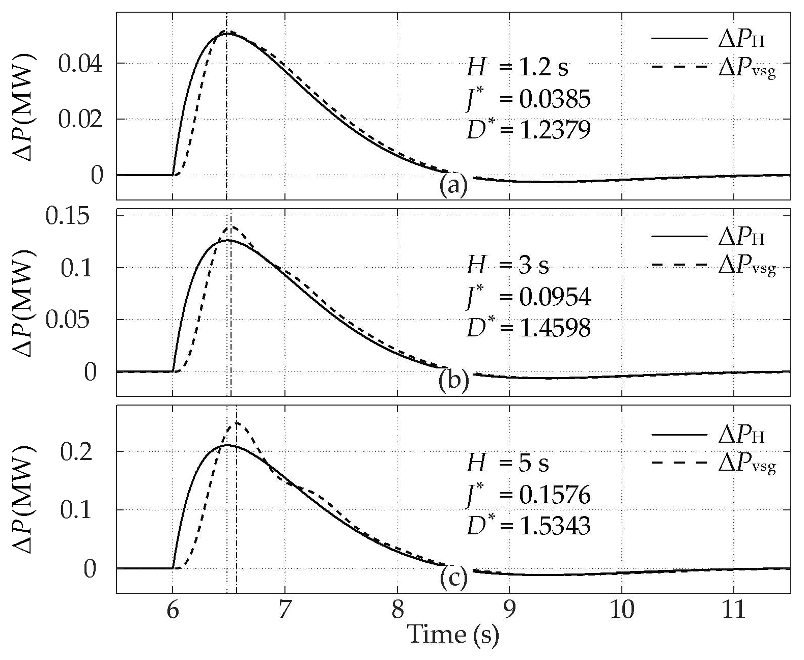
H)) under the three representative inertia targets are shown in
Figure 2.
As shown in
Figure 2, under different equivalent inertia targets, the VSG inertial-support power response maintains high consistency with the target inertial-support power response. Since the initial power increase rate of the VSG power response is slightly lower than that of the target inertial-support power response, its peak value is correspondingly higher than the target response peak, thereby ensuring consistency in the cumulative power contribution during the inertial-support stage.
The contour of the comprehensive error function
E(
H,
J,
D) on the
J–D plane under a given
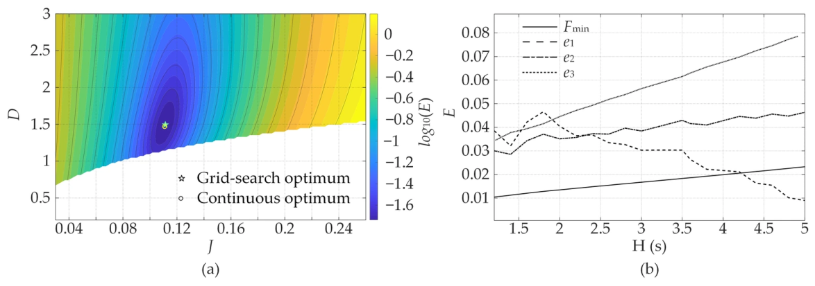
H is shown in
Figure 3a. As can be observed from
Figure 3a, the comprehensive error function exhibits a single distinct low-error region on the
J–
D plane. These results indicate that, within the selected parameter boundaries, the boundary-constrained optimization provides an identifiable numerical optimum. The accuracy of the obtained
J and
D values is mainly affected by the grid resolution and the convergence tolerance of the continuous optimization.
The minimum comprehensive error
Fmin(
H) under different values of
H is shown in
Figure 3b. Within the range of
H = 1.2~5
, the initial power increase rate error
e1, the relative error of the power integral during the inertial-support period
e2, and the normalized power error
e3 all remain at low levels. This indicates that the obtained VSG parameters can achieve good power-response equivalence under different equivalent inertia targets. In particular,
e3 increases slightly as
H increases, suggesting that the overall waveform matching of the power response becomes more difficult under higher equivalent inertia targets.
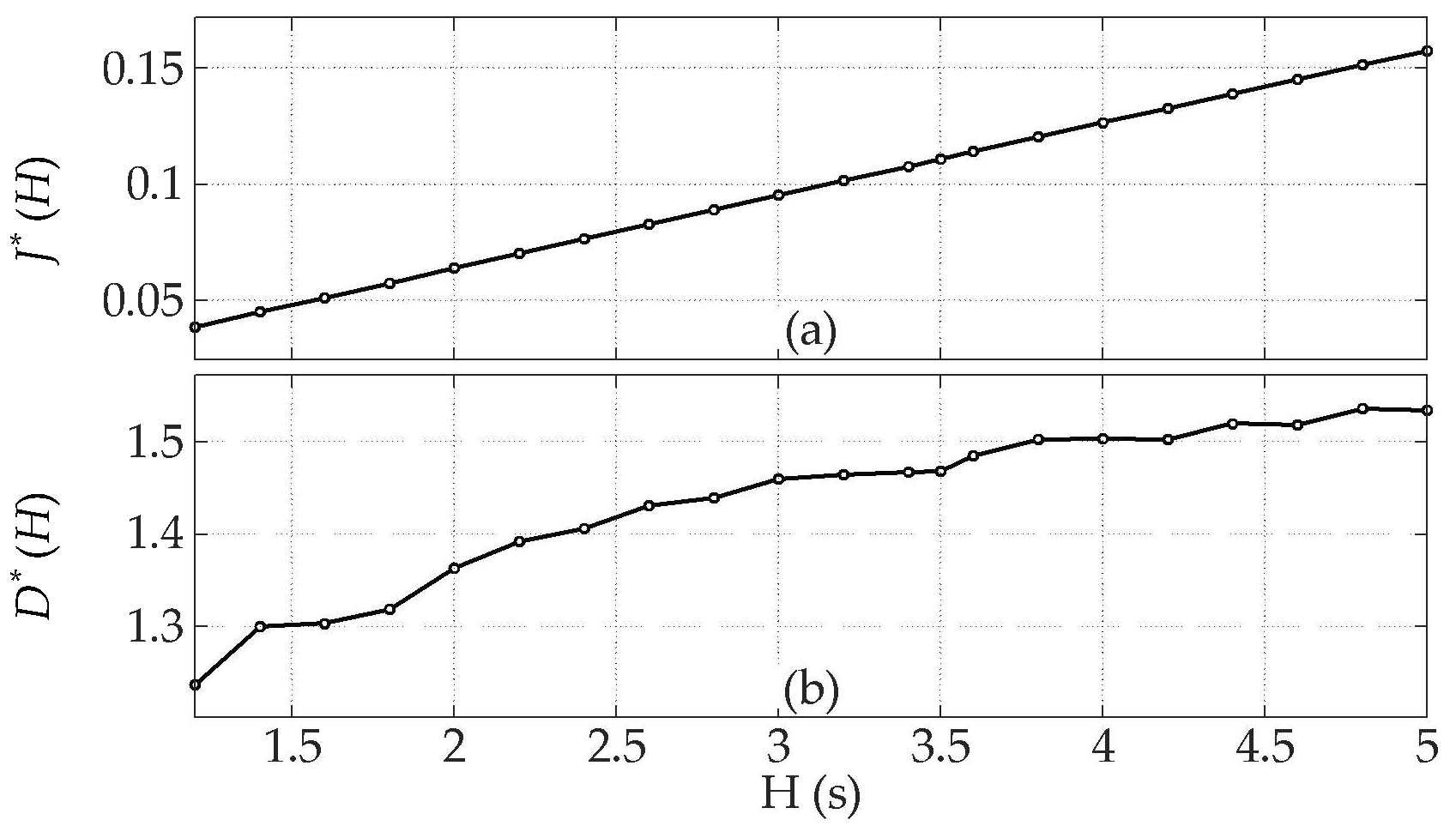
The VSG parameter configuration results under different equivalent inertia targets are shown in
Figure 4. As shown in
Figure 4, as the equivalent inertia target
H increases, the configured inertia parameter
J*(
H) increases approximately linearly, indicating that
J mainly determines the intensity of the VSG inertial-support response. The damping parameter
D*(
H) first increases and then tends to saturate as
H increases, suggesting that
D is mainly used to regulate the damping characteristics of the power response and the waveform near the peak, while its marginal effect becomes weaker under higher inertia targets.
3.3. Inertia-Target Conversion and Parameter Configuration for RSC/GSC Dual-VSGs
For an energy-storage DFIG using the dual-VSG strategy, the overall equivalent inertia target of the turbine should be converted into inertia indices under the respective power bases of the stator side and the GSC side. The power-response equivalence method is then applied separately to solve the corresponding J and D control parameters.
To ensure a consistent power response corresponding to the same turbine-level equivalent inertia target
Hwt under different operating conditions, fixed power bases are adopted for the overall turbine, the stator side, and the GSC side. Let
Swt denote the turbine power base, and let
Ss and
Sgsc denote the power bases of the stator side and the GSC side, respectively. Then,
Let
and
denote the equivalent inertia of the stator side and the GSC side, respectively, converted to the turbine power base. According to (21)–(22), the overall equivalent inertia target
of the turbine is decomposed as
where
and
represent the equivalent inertia of the stator side and the GSC side converted to the turbine power base, respectively. Their specific values are determined by the rotor kinetic-energy reserve and the available state of the DC-side energy storage.
Furthermore, according to (22), the target equivalent inertia of the stator side and the GSC side under their respective power bases can be obtained as
Then, for the corresponding equivalent inertia targets, the stator-side VSG and the GSC-VSG control parameters are solved according to (31):
Equations (33)–(36) give the calculation relationship from the overall turbine-level equivalent inertia target Hwt to the dual-VSG control parameters Js, Ds, Jgsc, and Dgsc. The overall turbine-level inertia target is first decomposed into the stator-side and GSC-side inertia components under the turbine power base, then converted into the equivalent inertia targets under the respective power bases of the two sides. Finally, the VSG control parameters of both sides are obtained using the power-response equivalence method. By allocating the inertial-support tasks between the stator side and the GSC side, this method maintains the stability and controllability of the overall turbine-level inertial-support power response under different rotor speeds and energy-storage states. When the allocated equivalent inertia of a channel is zero, this channel is not assigned an inertial-support response target, and the power-response-equivalence-based parameter calculation is not performed. In this case, the corresponding VSG parameters are set to the minimum allowable J and the maximum allowable D within the predefined parameter boundaries, so that the inertial response is minimized while sufficient damping is maintained.
4. Dual-VSG Coordinated Frequency-Support Control Strategy for Energy-Storage DFIG Wind Turbines
Dual-VSG coordinated control should determine the inertia shares and PFR power allocation of the stator side and the GSC side according to the rotor kinetic-energy reserve, the DC-side energy-storage state, and the GSC upward power margin, so that the overall frequency-support power response of the turbine meets the specified target.
4.1. Dual-Channel Frequency-Support Capability Characterization and Boundary Constraints
The stator-side frequency-support power is provided by the release of rotor kinetic energy and is constrained by the rotor speed. The GSC-side frequency-support power is provided by the release of DC-side energy storage and is constrained by both the storage SOC and the GSC upward power margin.
According to the quadratic relationship between rotor kinetic energy and rotor speed, the rotor kinetic-energy reserve coefficient
ρs is defined as
where
ωr,0 is the rotor mechanical angular speed before the frequency disturbance;
ωmin is the minimum allowable rotor speed;
ωr,N is the rated rotor speed;
ρs characterizes the releasable rotor kinetic-energy level under the current rotor speed, and its calculated value is limited to the range [0, 1].
The available-state coefficient of the DC-side energy storage
ρes is defined as
where SOC
0 is the state of charge of the energy storage before the frequency disturbance; SOC
min is the minimum allowable state of charge; SOC
N is the reference state of charge;
ρes characterizes the energy reserve level of the DC-side energy storage available for frequency support, and its calculated value is limited to the range [0, 1].
The GSC upward power margin coefficient
ρp is defined as
where
Pgsc,N is the GSC power upper limit;
Pgsc,0 is the GSC active-power before the frequency disturbance;
ρp characterizes the upward power margin of the GSC at the pre-disturbance operating point, and its calculated value is limited to the range [0, 1].
The storage SOC and the GSC upward power margin jointly determine the available frequency-support capability of the GSC side. Therefore, the available frequency-support coefficient of the GSC side is defined as
where
ρgsc simultaneously reflects the energy constraint of the storage system and the upward power margin constraint of the GSC. When the storage SOC is low or the GSC upward power margin is insufficient,
ρgsc decreases. When both the storage SOC and the GSC upward power margin are sufficient,
ρgsc approaches one.
Under the current operating condition, the maximum equivalent inertia components that can be undertaken by the stator side and the GSC side under the turbine power base are denoted as and , respectively. Here, is determined by the rotor kinetic-energy reserve and the rotor-speed lower limit, whereas is jointly determined by the storage SOC and the GSC upward power margin. These two quantities constitute the boundary constraints for dual-VSG inertia allocation.
4.2. Coordinated Allocation of Inertial-Support and Primary-Frequency-Control Power for Dual-VSGs
The dual-VSG frequency-support power allocation is used to coordinate the inertial-support and PFR power outputs of the stator side and the GSC side, so that the overall frequency-support response of the turbine satisfies the prescribed target. In terms of the allocation logic, when the available capability of the GSC side is sufficient, DC-side energy storage is preferentially utilized for support so as to reduce the release of rotor kinetic energy and its impact on wind-energy capture. When the GSC side is constrained, the stator side provides supplementary support to maintain the overall frequency-support capability of the turbine.
According to the rotor kinetic-energy reserve coefficient of the stator side and the availability coefficient of the GSC side, the GSC-side inertia-sharing coefficient
is defined as
where
γgsc represents the proportion of the overall turbine-level equivalent inertia target undertaken by the GSC side. The higher the GSC-side availability coefficient is, the larger
γgsc becomes. When the GSC-side availability coefficient decreases, the inertial-support task is transferred to the stator side. When both
ρs and
ρgsc are zero, neither side has an inertial-support margin under the current operating condition.
For a given turbine-level equivalent inertia target
Hwt, the equivalent inertia component of the GSC side is
The equivalent inertia component of the stator side is determined by the overall turbine-level target and the actual share undertaken by the GSC side, and is subject to the stator-side inertia boundary constraint:
Equations (42) and (43) give the inertia allocation relationship in which the GSC side is given priority and the stator side provides supplementary support. When the stator-side limit in (43) is not activated, the turbine can realize the target equivalent inertia
under the current operating condition. When the stator-side limit is activated, the current rotor kinetic-energy reserve and the available GSC capability are insufficient to fully realize the target inertial support. In this case, the maximum achievable turbine-level inertia is
According to (35), and can be converted into the equivalent inertia targets Hs and Hgsc under the respective power bases of the two sides. The corresponding stator-side VSG and GSC-VSG control parameters can then be calculated according to (30) and (31).
Since the PFR power command is linearly determined by the frequency deviation and the droop coefficient, the PFR power commands of the stator side and the GSC side can be directly allocated according to the inertia-sharing ratio of the two sides. The inertia-sharing ratios of the stator side and the GSC side are defined as
Let
Kf,wt denote the overall droop coefficient of the turbine. Then, the droop coefficients of the stator side and the GSC side are given by
Equations (42), (43) and (46) give the dual-VSG frequency-support power allocation method considering both inertial support and PFR. For the inertial-support component, the GSC-side share is first determined by the GSC-side inertia-sharing coefficient, and then the stator-side share is determined according to the overall turbine-level target. The boundary constraints are further used to assess the feasibility of the frequency-support target under the current operating condition. For PFR, the droop coefficients are allocated according to the inertia-sharing ratios of the two sides.
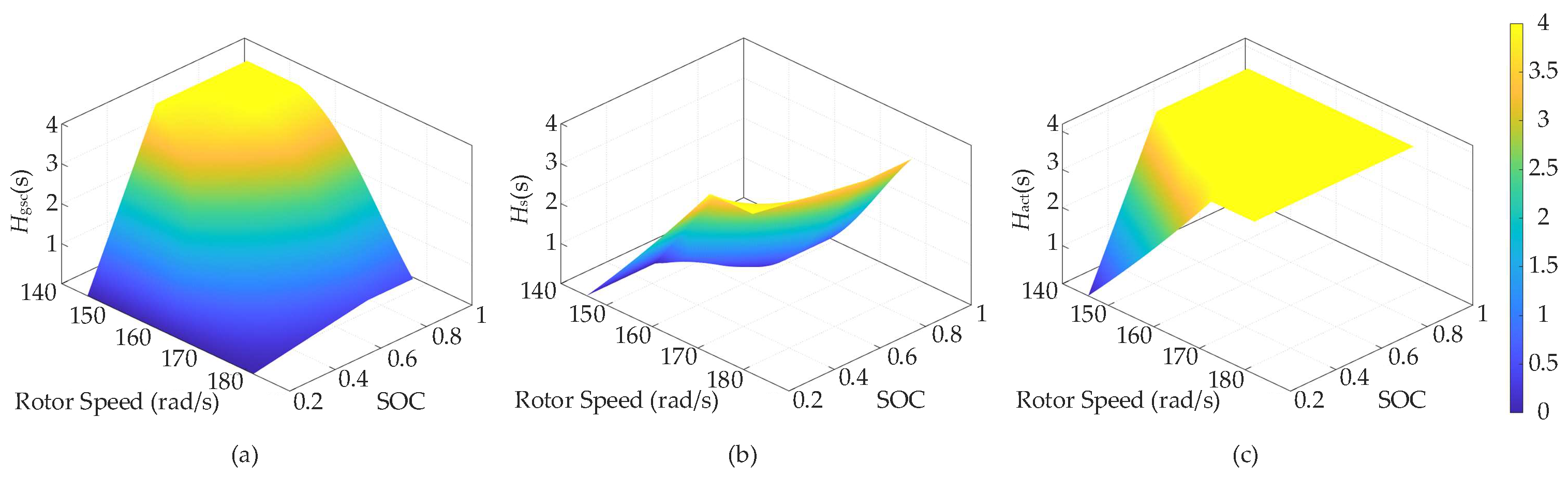
Let the turbine-level equivalent inertia target be
Hwt = 4 s. The allocation results of the inertia shares of the stator side and the GSC side under different rotor-speed and storage-SOC conditions are shown in
Figure 5. Here, the rotor speed characterizes not only the rotor kinetic-energy reserve of the stator side, but also affects the GSC upward power margin through its influence on the pre-disturbance GSC active-power
Pgsc,0. The SOC characterizes the available energy level of the DC-side storage system.
As shown in
Figure 5a, when the SOC is high and the rotor speed is low, the available capability of the GSC side is strong, and
Hgsc is relatively large, which reflects the allocation logic of preferentially utilizing DC-side energy storage for support. As shown in
Figure 5b, as the share undertaken by the GSC side decreases, the inertia share of the stator side,
, correspondingly increases, indicating that the frequency-support task is transferred from the GSC side to the stator side in order to maintain the overall inertial-support capability of the turbine. As shown in
Figure 5c, in the medium- and high-speed regions or the high-SOC region, the achievable WT-level inertia
Hact can reach the target inertia
Hwt. By contrast, in the low-speed and low-SOC region,
Hact is lower than the target value, indicating that the turbine frequency-support capability is limited under the current operating state.
Since the PFR droop coefficients are directly determined according to the inertia-sharing ratios of the two sides, their variation trends are consistent with the allocation results of Hs and Hgsc.
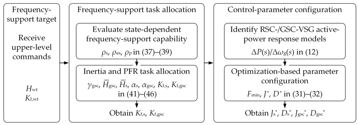
The VSG parameter configuration based on frequency-support power-response equivalence, together with the allocation of the frequency-support shares between the stator side and the GSC side, jointly constitutes the core of the dual-VSG coordinated control of the energy-storage DFIG wind turbine. Its overall control structure is shown in
Figure 6.
6. Conclusions
This paper investigates the dual-VSG coordinated frequency-support problem of energy-storage DFIG wind turbines. The results show that the difference between the equivalent inertia definition and the VSG closed-loop power-response model makes it difficult to directly determine VSG control parameters from a target inertia. The frequency-support power-response equivalence method establishes the correspondence between the equivalent inertia target and the RSC-VSG/GSC-VSG control parameters, enabling the overall inertial-support power response of the wind turbine to match the specified target. On this basis, rotor kinetic-energy reserve, storage SOC, and GSC upward power margin are considered to coordinate the inertia-support and PFR power contributions of the stator side and the GSC side.
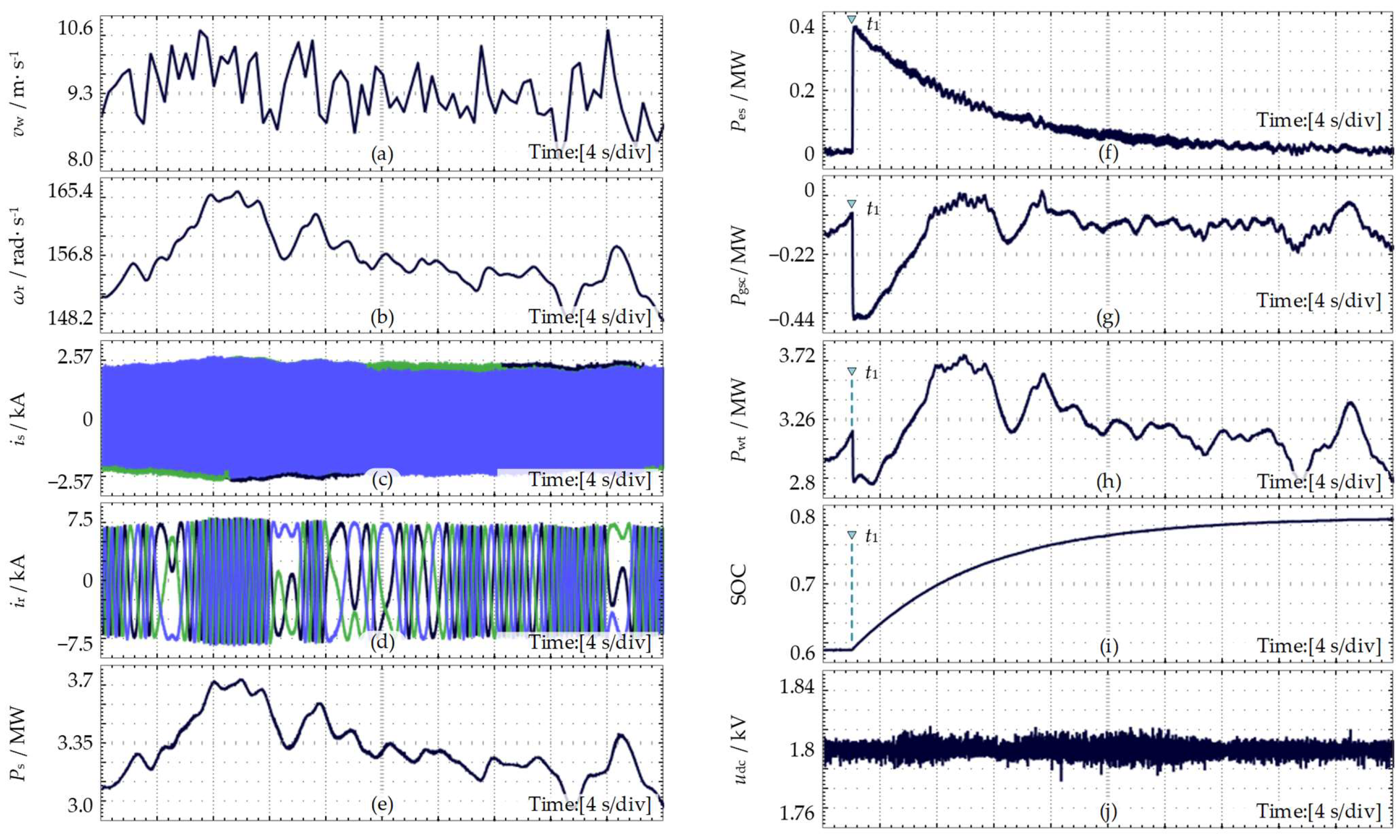
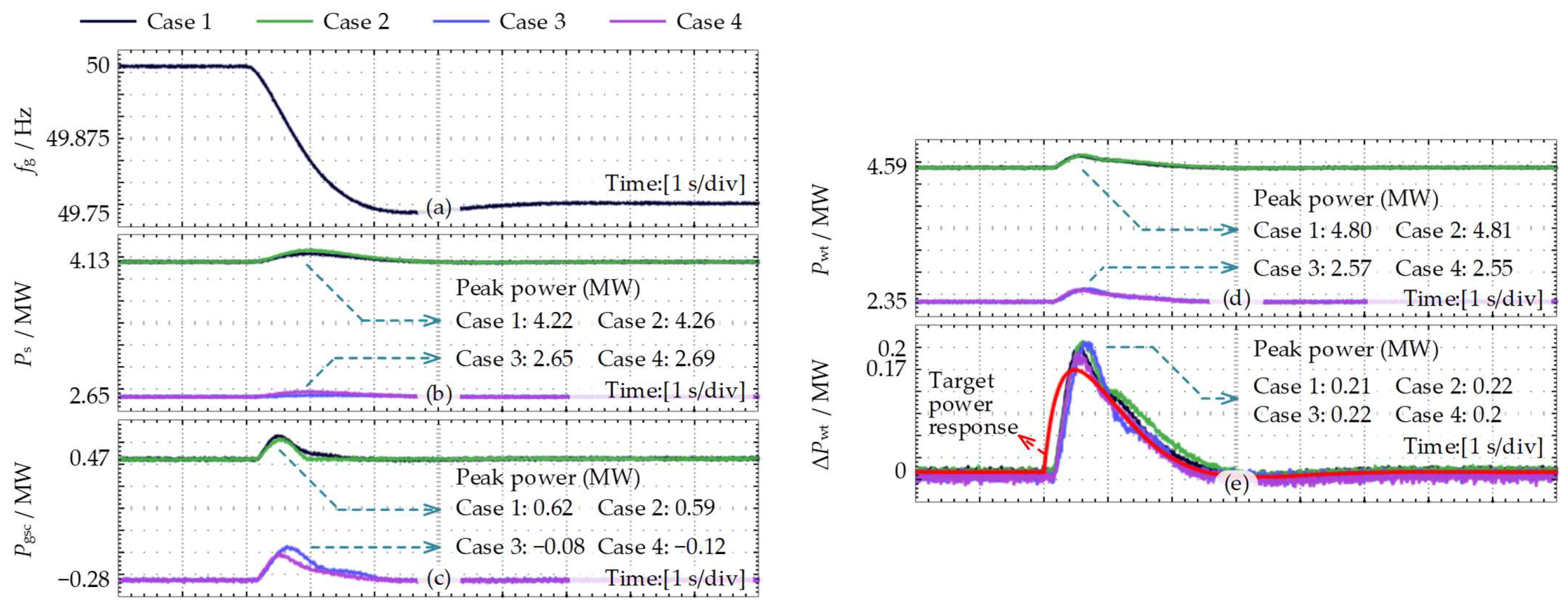
Hardware-in-the-loop validation shows that, under four typical operating conditions with high/low wind speeds and high/low SOC levels, the proposed method adjusts the frequency-support contributions of the stator side and the GSC side according to the operating state. Under all operating conditions, the inertial-support power response of the wind turbine tracks the target response, and the frequency-support power response remains consistent and stable throughout the main support interval. These results demonstrate that the proposed method maintains the stability and controllability of the turbine-level frequency-support response under operating-state variations, thereby improving the frequency-support performance of energy-storage DFIGs over a wide operating range.
Future work will extend the present turbine-level frequency-support control study to multi-turbine parallel operation and wind-farm-level applications, with a focus on coordinated configuration and stable control of the frequency-support power response of energy-storage DFIG clusters.