Abstract
Enhanced oil recovery (EOR) techniques are essential for maximizing hydrocarbon extraction from mature reservoirs. CO2 injection (CO2-EOR) is a promising technology that improves oil recovery while contributing to greenhouse gas reduction. This study investigates the potential of miscible CO2-enhanced oil recovery (CO2-EOR) in the MakXX oilfield of southeastern Kazakhstan. The aim is to assess oil displacement efficiency and its impact on key rock properties, including porosity, permeability, and mineral composition, under reservoir conditions. Core flooding experiments were conducted at 13 MPa and 42 °C using high-precision equipment to replicate reservoir conditions. The core was analyzed before and after CO2 injection using SEM, EDS, and XRD. The results revealed a 54% oil recovery efficiency, accompanied by a 19% decrease in permeability and 8% reduction in porosity due to mineral precipitation and clay transformation. These findings provide insight into the performance and limitations of CO2-EOR and support its application in similar lithology. To confirm and upscale laboratory observations, numerical simulation was conducted using a compositional model. The results demonstrated improved oil recovery, pressure stabilization, and enhanced sweep efficiency under CO2 injection, supporting the scalability and field applicability of the proposed EOR approach.
1. Introduction
Enhanced oil recovery (EOR) techniques become essential during the mature phase of an oilfield, following primary and secondary recovery. At this stage, oil production declines due to reduced reservoir pressure and the presence of unswept oil regions after water injection. The most effective EOR techniques include thermal, chemical, microbial recovery, and polymer flooding [1], methods also applied in Kazakhstani oilfields [2]. These methods not only enhance recovery rates but also mitigate reservoir inefficiencies inherent in earlier recovery stages. Notably, polymer flooding has shown promise in increasing displacement efficiency by modifying the viscoelastic behavior of injected fluids. For instance, the interaction of elasticity and wettability was explored in recent studies, revealing the enhanced mobilization of oil droplets [3]. As the primary and secondary recovery methods only recover a limited amount of the remaining oil, enhanced oil recovery techniques such as CO2 injection have been developed to further extract oil from mature fields. These methods improve the efficiency of oil recovery by addressing the limitations of earlier methods, such as pressure maintenance and the displacement of unswept oil [4].
The CO2-EOR method has gained significant attention due to its dual benefits: enhancing oil recovery and potentially reducing CO2 emissions, a major greenhouse gas contributing to climate change [5]. The CO2-EOR method not only helps in increasing the recovery factor by injecting CO2 into reservoirs, but it also has a significant role in reducing CO2 emissions. By capturing and injecting CO2 into deep reservoirs, where it can be stored safely, this method addresses both energy and environmental concerns [6]. Moreover, as an environmentally friendly alternative, CO2-EOR can potentially serve as a tool for carbon sequestration, which plays an important part in Kazakhstan’s national strategy for reducing its carbon footprint [7].
As an EOR method, the CO2-EOR process is categorized into two primary methods: miscible CO2 displacement, where CO2 fully mixes with the oil to reduce its viscosity and improve flow, and immiscible CO2 displacement, where CO2 does not mix but instead creates pressure to mobilize the oil [8,9]. Moreover, the impact of CO2 injection on oil recovery is generally determined by various factors, such as the mineral composition of the reservoir rock, the properties of the oil, and the prevailing temperature and pressure conditions [10]. Rock–gas interactions can result in either enhancement or reduction in poroperm parameters, depending on the rock composition [11]. Enhancement is typically linked to K-feldspar dissolution, as seen in shales [12], while reduction is attributed to the precipitation of Ca(HCO3)2 and NaCl, as observed in carbonates [5,13]. Therefore, the preceding experimental investigation is required prior to field scale pilot testing. The pioneering laboratory testing on the Kazakhstani reservoir core samples [4] revealed permeability reduction due to clay mineral alteration and halite precipitation. Moreover, the study suggested that the variability in the results necessitates a larger number of tests and the involvement of additional oilfields, and covering the latter is one of the goals of this study.
The efficiency of miscible displacement is heavily dependent on achieving the minimum miscibility pressure (MMP), which varies across reservoirs and directly influences the contact between CO2 and oil [14]. Studies indicate that achieving MMP can significantly improve recovery by increasing the displacement efficiency and reducing residual oil saturation. In contrast, immiscible CO2 injection relies on volumetric sweep efficiency, which is influenced by reservoir heterogeneity and pressure maintenance. Furthermore, laboratory studies have shown that CO2 injection in carbonate reservoirs can lead to increased pore space heterogeneity due to localized dissolution and precipitation processes, emphasizing the need for a detailed understanding of mineralogical changes. Recent advances in experimental setups, such as dynamic core flooding systems, allow for more precise simulation of reservoir conditions and better evaluation of CO2–rock interactions under varying temperatures and pressures [15]. This finding aligns with observations in similar lithologies, where the presence of reactive clay minerals amplifies CO2-induced alterations [16].
The role of CO2 in reservoir transformation has garnered increasing attention in recent years, particularly due to its capacity to alter the geochemical equilibrium between formation fluids and reservoir rocks. Such interactions include clay swelling, mineral dissolution and precipitation, and changes in porosity and permeability, all of which directly affect the performance of EOR operations. Experimental studies have demonstrated that CO2 injection can significantly influence these reservoir properties, leading to enhanced oil mobility and production rates [17]. Moreover, the observed petrophysical changes emphasize the necessity of thoroughly understanding fluid–rock interactions under actual reservoir conditions. This understanding is essential to ensure both the efficiency and integrity of CO2-based EOR projects over the long term, as highlighted in recent investigations [18].
This study integrates the laboratory investigation of miscible CO2-induced enhanced oil recovery from the east-southern Pre-Caspian region under controlled laboratory conditions using the core samples from the MakXX oilfield (field name partially concealed for confidentiality). SEM and EDS analyses before and after testing reveal the effects of miscible CO2 on reservoir properties and rock structure. The findings provide a preliminary laboratory-scale assessment of this method’s feasibility. Despite several studies on CO2-EOR, limited data exists on Kazakhstani core samples under near-miscible conditions, especially regarding their effect on rock structure. This study represents the first comprehensive integration of laboratory core flooding, mineralogical analysis, and numerical simulation using native Kazakhstani reservoir core samples. In particular, it focuses on quartz–albite-dominated sandstone lithology under reservoir-simulated miscible CO2 conditions—a combination not previously explored in this regional context. Therefore, the study fills an important knowledge gap and contributes to the foundation for field-scale CO2-EOR deployment in the Pre-Caspian Basin. The following sections describe the geological setting, experimental methodology, analysis techniques, and discussion of displacement efficiency and structural changes due to CO2 injection.
2. Materials and Methods
2.1. Geological Settings
The MakXX oilfield is located in the southeastern part of the Pre-Caspian Basin, on the eastern shore of the Caspian Sea, and administratively belong to the Atyrau Region, in the Republic of Kazakhstan. The exploratory, appraisal, and production wells have penetrated deposits ranging from the Kungurian age to the Quaternary system in the field. The geological structure of this area is determined by salt-dome tectonics (Figure 1). The oil-bearing horizons are associated with the sandy-clay deposits of the Middle Jurassic. The oil reservoirs are stratified, anticlinal, and tectonically and lithologically sealed. The boundaries of oil accumulation for all horizons are defined by contour water and tectonic faults.
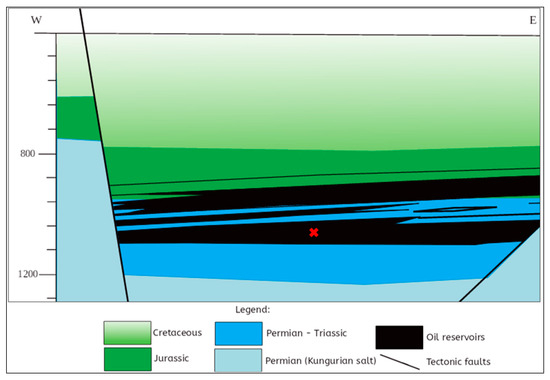
Figure 1.
Profile section along the well line of the field (the red dashed box in the geological cross-section delineates the exact depth and location of the core sampling point utilized in this study [19]).
The core samples were obtained from the target oilfield, with key reservoir and core parameters summarized in Table 1. The core selected for this study was retrieved from a depth of 1057.47 m, located within the Permian–Triassic interval and corresponding to the main oil-bearing horizon of the field. This depth was chosen due to its representative porosity and permeability characteristics, as well as its position near the central part of the field structure—approximately beneath the anticlinal crest, as illustrated in the geological cross-section in Figure 1 (the core location is marked by a red dashed box). While the setup provides valuable insight into reservoir behavior under miscible CO2 injection, certain methodological limitations should be acknowledged. The measurements were obtained from a single core plug, and repeatability or experimental uncertainty was not assessed. To better understand the influence of mineralogical composition on CO2-EOR performance, future work should incorporate multiple core samples and a range of injection pressures and temperatures to establish reproducible patterns.

Table 1.
The reservoir and core characteristics of the core sample prior to CO2 injection.
A 5 mm thick slice was cut from the central portion of the core sample for detailed analysis. This slice was subjected to Scanning Electron Microscopy (SEM) examination both prior to and following the flooding experiments to detect any alterations in the microstructure caused by the process. To ensure the clarity and quality of SEM imaging, the surfaces of the slices were carefully polished. Additionally, X-ray diffraction (XRD) was carried out on the samples to accurately determine their mineralogical composition and concentrations.
2.2. Oil and Brine Used in Core Flooding
The reservoir oil from the oilfield was employed in the experiment for saturation purposes. Moreover, the chemical composition of the reservoir water from the field was replicated by mixing salts in precise proportions as presented in Table 2.
Table 2.
Chemical composition of brine used in core samples saturation (unit: g/L).
2.3. Minimum Miscible Pressure Estimation
Prior to the experiments, the minimum miscibility pressure (MMP) for the core sample was determined to be 13.2 MPa, based on empirical correlations that account for oil composition and reservoir conditions [4]. Among these, the average values obtained from the correlations proposed by Cronquist, 1978 [20], Li et al. 2012 [21], and Orr and Jensen, 1984 [22], as reported by Shabdirova et al. (2024) [4], served as the reference framework. These correlations incorporate reservoir temperature, the molecular weight of heavy hydrocarbon fractions (C7+), and the mole fractions of volatile and intermediate components (e.g., CH4, N2, CO2, C2–C4).
Although this method is commonly used for preliminary MMP screening, it inherently involves uncertainties and does not replace experimental validation. The estimated MMP value was used to guide the selection of the experimental pressure (13 MPa), ensuring near-miscible conditions and enabling the evaluation of phase behavior and displacement efficiency under simulated reservoir conditions.
To estimate the MMP, the following parameters were considered: reservoir temperature, molecular weights of the C5+ and C7+ fractions, mole fractions of volatile components (e.g., N2 and CH4), and mole fractions of intermediate components (e.g., CO2, H2S, and C2–C4). Direct experimental validation of the estimated MMP—such as slim-tube, rising bubble, or vanishing interfacial tension (VIT) tests—was not feasible in this study due to the unavailability of suitable high-pressure laboratory equipment. As a result, the estimated value of 13.2 MPa was benchmarked against the literature data for similar oil compositions and conservatively adjusted to 13 MPa to ensure near-miscible conditions in the core flooding experiments. While empirical correlations provide a useful preliminary estimate, we acknowledge that they are insufficient as standalone methods. Future work will include direct MMP validation using experimental techniques once laboratory resources become available.
A sensitivity analysis around the estimated MMP was conducted and is discussed in Section 4. Based on the variability among the applied correlations and benchmarking against the literature values, the uncertainty of the estimated MMP was evaluated to be approximately ±1 MPa. Deviations below MMP can result in partial miscibility or immiscible displacement, reducing sweep efficiency and increasing residual oil saturation. Conversely, operating significantly above MMP may lead to premature gas breakthrough, asphaltene precipitation, and undesired changes in phase behavior. These deviations could affect both laboratory outcomes and field-scale CO2 injection strategies. As such, we emphasize the importance of direct experimental determination in future work to reduce uncertainty and enhance predictive confidence. Additional details can be found in the preceding study by Shabdirova et al. [4].
2.4. Experimental Procedure
The experimental procedure consisted of the following steps:
- ˗
- Core samples were saturated with model reservoir brine under controlled pressure and temperature conditions, with injection rates and fluid volumes carefully recorded.
- ˗
- Oil was subsequently injected until all brine was displaced, followed by a stabilization period of 24 h to ensure equilibrium.
- ˗
- CO2 was injected at a constant rate, and the produced fluid mixture (oil, water, and CO2) was separated and measured using a dedicated separator.
- ˗
- To assess the impact of CO2 injection, porosity and permeability were measured both before and after the experiment using the same core plug. These measurements were conducted under identical pressure and temperature conditions (13 MPa, 42 °C) using a single core sample, allowing reliable comparison of the property alterations.
- ˗
- SEM and XRD analyses were performed on the post-experiment samples to evaluate mineralogical and structural transformations. These methods provided a comprehensive understanding of the dynamic processes occurring within the reservoir rock during CO2 injection, offering valuable insights into optimizing EOR operations.
As a first step, a computer-controlled saturator for unattended saturation AST-600 (Taha Kimia Tajhiz Co., Tehran, Iran) was employed for the uniform saturation of core samples with synthetic reservoir water, ensuring control over air evacuation and saturation pressure.
Figure 2 illustrates the schematic of the experimental CO2 flooding setup, comprising the injection system, accumulator, core holder, heating elements, and effluent collection. To enhance clarity, instruments are color-coded according to function: green indicates flow control components, such as the CO2 cylinder, intermediate reservoirs, and injection pumps, while yellow designates pressure monitoring elements, including sensors and gauges. A description of these functionalities has been added to the figure caption for reader reference.
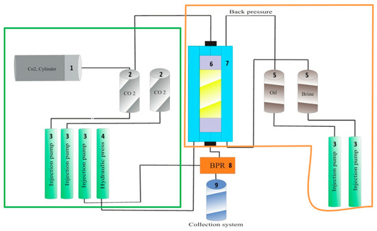
Figure 2.
General schematic of the CO2-EOR experimental setup. 1—CO2 gas cylinder; 2—CO2 reservoirs; 3,4—injection pumps and press; 5—oil and brine supply reservoirs; 6—core holder; 7—temperature control jackets; 8—back-pressure regulator; 9—disposed fluid collection system. Note: Orange rectangle—core flooding PLS-200 system (presented in Figure 3); green rectangle—CO2 injection system (presented in Figure 4).
The system is divided into two functional blocks. The CO2 injection module (green) delivers gas at a controlled rate and pressure into the core flooding apparatus. The core flooding unit (highlighted in orange in Figure 2) corresponds to the PLS-200 system (Core Laboratories, Houston, TX, USA) and includes the oil and brine reservoirs, additional injection pumps, the core holder (Element 6), temperature control jacket (Element 7), back-pressure regulator (Element 8), and effluent collection system (Element 9). These components collectively ensure precise simulation of subsurface conditions and control of fluid flow through the rock sample.
A critical component of the setup is the back-pressure regulator (BPR) (Element 8), which maintains the outlet pressure above the minimum miscibility pressure (MMP). This ensures that CO2 remains in a supercritical or dense phase throughout injection, a prerequisite for stable displacement and realistic reservoir simulation.
The temperature jacket (Element 7) maintains a constant experimental temperature of 42 °C, while the core holder (Element 6), made of high-strength stainless steel, applies uniform confining pressure to the rock sample. A hydraulic loading mechanism, rubber sleeve, and thermocouples enable controlled mechanical loading and real-time monitoring of thermal conditions.
The system operates at pressures up to 30 MPa and temperatures exceeding 70 °C, enabling high-fidelity assessments of fluid–rock interactions during CO2-EOR processes. A check valve ensures unidirectional fluid flow, preventing backflow and preserving experimental accuracy.
The method used to maintain outlet back-pressure, via a manually adjustable back-pressure regulator, is described in Section 2.4, and instrument-specific roles are now clarified in the caption of Figure 2, improving interpretability for researchers and practitioners. Following the saturation, core flooding experiments were conducted using the PLS-200 system (Figure 3), a high-precision apparatus designed to replicate reservoir conditions under controlled pressure and temperature. The flooding experiment was conducted at a constant pressure of 13 MPa and temperature of 42 °C, controlled using the integrated hydraulic and thermal regulation system of the PLS-200 unit. The pressure control was achieved using a manual hydraulic pump and pressure regulators with ±0.1 MPa accuracy, while temperature was maintained by a thermostatic jacket with ±0.5 °C precision. The CO2 injection flow rate was set at 0.2 cm3/min, using high-precision syringe pumps with continuous monitoring by calibrated flow meters. The integration of AST-600 (Taha Kimia Tajhiz Co., Tehran, Iran) and PLS-200 (Core Laboratories, Houston, TX, USA) ensures a seamless transition from sample preparation to experimental analysis, minimizing inconsistencies in initial fluid distribution. This methodological approach enhances the accuracy of fluid displacement studies, providing reliable data for advanced research on EOR.
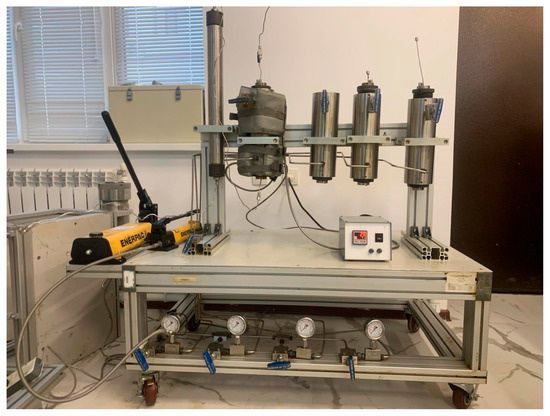
Figure 3.
Core flooding PLS-200 system.
Comparable methodological frameworks have been applied in related studies on polymer-based displacement systems under elevated fracturing pressures, confirming the relevance and applicability of such high-fidelity setups in EOR research [23]
Fluid measurement cylinders of the core flooding system (Figure 3) provide precise volume readings (±0.01 mL). The confining pressure gauge continuously monitors applied stress, ensuring accurate subsurface condition simulation with enhanced reliability through regular calibration. The hydraulic press, equipped with a manual pump, is essential for applying and maintaining the confining pressures specified in Table 1 for the core sample, ensuring precise simulation of reservoir stress conditions. Its ergonomic design and precision components ensure consistent pressure application, closely simulating reservoir conditions.
The configuration is tailored for advanced studies involving fluid flow and displacement in porous media under controlled conditions. Below is a detailed description of the unique components depicted:
- The setup includes multiple high-pressure core holders made from corrosion-resistant stainless steel, ensuring uniform pressure distribution for accurate fluid displacement experiments.
- An integrated network of pipes and valves controls fluid injection and extraction, enabling smooth phase transitions between brine, oil, and gas. High-precision valves ensure leakage-free operation.
- A transparent fluid storage bottle and collection unit facilitate real-time monitoring of displaced fluids. Pressure and flow sensors connected to control units provide continuous feedback for precise experimental control and data acquisition.
- The core holders and fluid management system are mounted on a modular, mobile aluminum frame, enhancing adaptability and integration with other experimental setups. An auxiliary power distribution strip ensures reliable operation, minimizing electrical interference.
The integration of high-pressure core holders with a fluid management system enhances experimental reliability while reducing complexity. It provides critical insights into EOR efficiency, fluid displacement, and CO2 sequestration under reservoir conditions. Its modular design ensures adaptability for advanced research in petroleum and environmental engineering.
Figure 4 presents an advanced CO2 injection system designed to replicate reservoir conditions for fluid displacement studies. The system ensures precise regulation of pressure (±0.1 MPa), temperature (±0.5 °C), and gas flow rate (±0.01 mL/min). The primary components are detailed as follows:
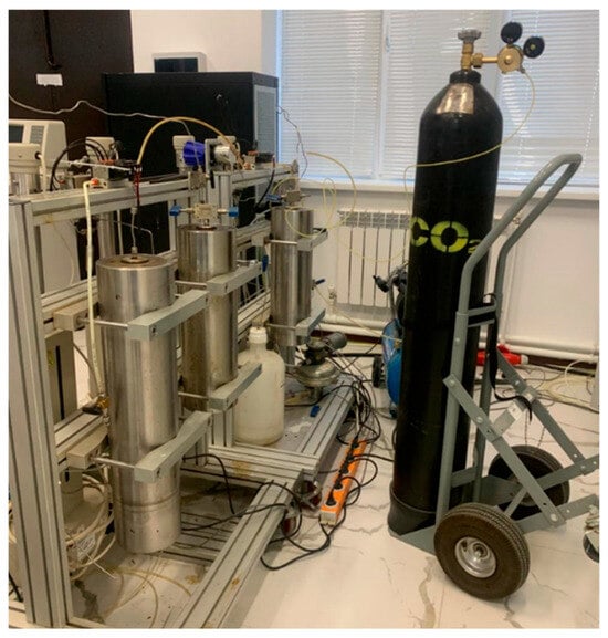
Figure 4.
CO2 injection system of the CO2-induced enhanced oil recovery experimental setup.
- ˗
- CO2 Cylinder: A high-capacity (up to 50 L) CO2 storage unit equipped with a pressure regulator to maintain a stable and controlled gas supply, ensuring consistent injection conditions.
- ˗
- Pressure Regulator: A precision regulator that modulates CO2 flow to maintain the required pressure for experimental stability.
- ˗
- Stabilization Tank: A dedicated buffer unit designed to collect displaced fluids during CO2 injection or regulate fluid flow to prevent system fluctuations.
- ˗
- High-Pressure Tubing: A network of reinforced stainless-steel pipelines and hoses ensuring secure, high-pressure transport of CO2 and fluids between components, minimizing leakage risks and enhancing operational safety.
- ˗
- Monitoring Instruments (Pressure Gauges, Flow Meters): Integrated high-precision monitoring devices calibrated for real-time measurement and regulation of CO2 and fluid flow parameters.
The CO2 cylinder, with a high-precision pressure regulator, introduces carbon dioxide at a controlled rate, facilitating gas injection simulations for EOR studies and CO2 sequestration analysis. The pump ensures precise fluid injection into the core sample, maintaining stable flow rates and pressures while minimizing pulsation. A gas storage tank stabilizes CO2 flow, improving reproducibility.
2.5. Core Flooding Experimental Conditions
The sample from the MakXX oilfield was tested at 42 °C and 13 MPa. The sample was secured, and brine was injected for 2 h at 0.2 cm3/min until full saturation, followed by 24 h stabilization, under controlled conditions. Oil displaced brine under reservoir conditions, followed by a 24 h stabilization period. After that, CO2 was injected at a steady rate, with displaced fluid volume measured. Cleaning of the samples was performed using a Soxhlet apparatus with a benzene–alcohol solvent mixture. This process ensured the complete removal of hydrocarbons and impurities that could potentially alter the subsequent measurements. The Soxhlet apparatus operates on a cyclic principle, where solvent vapor condenses and washes the sample repeatedly until the cleaning process is complete.
To verify the effectiveness of the cleaning, samples were inspected under ultraviolet light for luminescence, and the solvent color was monitored as an additional control. This multi-step verification guaranteed that the samples were entirely free of hydrocarbon residues. Post-cleaning, samples were dried at 60 °C in a drying oven to achieve a stable, constant weight, ensuring the reliability of subsequent analyses.
To minimize atmospheric moisture adsorption, the dried samples were stored in glass desiccators and transferred for further standard analyses, such as porosity and permeability testing. These analyses were conducted before and after flooding on the same core plug under simulated reservoir conditions (13 MPa, 42 °C). Precise geometric parameters of cylindrical samples were determined using the automated “Abacus” system (Abacus Analytical Systems GmbH, Berlin, Germany), which integrated weight measurements from analytical scales (accurate to 0.001 g) with dimensional data obtained through repeated measurements using a digital caliper.
For grain volume determination, a calibrated helium porosimeter was employed. The porosimeter utilizes Boyle’s law for high-precision calculations, ensuring minimal deviation in volume measurements.
These parameters provide foundational insights into the sample’s petrophysical properties, enabling a comprehensive evaluation of reservoir quality. It is important to note that the porosity determined represents open porosity, while mineral density refers to apparent values in cases where closed porosity is present. Absolute permeability was determined by using nitrogen gas as a flowing medium based on Darcy’s law.
This method allowed for a detailed quantification of the permeability values, providing critical insights into the fluid flow dynamics within the rock matrix. The results obtained are instrumental in predicting the reservoir’s production potential and informing enhanced oil recovery (EOR) strategies.
2.6. Scanning Electron Microscopy (SEM)
Core sample imaging was performed using the QUANTA 650 SEM (Thermo Fisher Scientific, Hillsboro, OR, USA) with an XFlash energy-dispersive (Bruker Nano GmbH, Karlsruhe, Germany) X-ray spectrometer, enabling high-resolution analysis of pore morphology, mineral distribution, and CO2-induced microstructural changes. Imaging under low-vacuum conditions with an LFD (FEI Company, Hillsboro, OR, USA) allowed detailed observation of pore structures, grain boundaries, and secondary alterations. The analysis is capable of identifying the textural evolution and new mineral phase formation during CO2 injection. Core ends (5–10 mm) were prepared for imaging to ensure consistency. This approach provided a comprehensive microstructural characterization, revealing key fluid flow mechanisms and enhancing the understanding of rock–fluid interactions in CO2-EOR.
2.7. X-Ray Diffraction Analysis (XRD)
Mineralogical analysis was conducted using an Ultima IV diffractometer (Rigaku Corporation, The Woodlands, TX, USA), which provided highly precise quantitative data on the mineral composition of the core samples. The samples, with particle sizes ranging from 5 to 10 microns, were analyzed at scattering angles between 5° and 60° with a step size of 0.05°/s. The XRD patterns obtained were compared against standard reference spectra to determine the normalized percentages of individual minerals. This approach enabled the identification of even minor mineral phases, which play a significant role in determining the reservoir’s reactivity and storage capacity during CO2 injection.
3. Results
Core Samples’ Characterization
Before CO2 flooding, the sample was composed of 61% quartz, 39% albite, 1% illite, 1% smectite, and 7% calcite, as determined by normalized XRD intensity. While the dominant components (quartz and albite) are chemically inert and not associated with formation damage, the presence of minor amounts of smectite and calcite may lead to pore clogging through specific mechanisms. In particular, smectite swelling and calcite dissolution followed by mineral reprecipitation under acidic CO2-rich conditions could contribute to permeability reduction during injection. The slight exceedance of 100% is attributed to peak overlap and rounding errors during XRD processing. Although the tested core is siliciclastic in nature, the insights can support screening workflows for CO2-EOR in similar lithologies with moderate clay content.
Pore blockage can arise from smectite swelling and the dissolution–reprecipitation of calcite under acidic CO2-rich conditions. In contrast, quartz and albite are chemically inert and unlikely to impair permeability. The mineral percentages may slightly exceed 100% due to overlapping peaks and rounding effects. Core flooding experiments conducted under controlled reservoir conditions (13 MPa and 42 °C) demonstrated an oil recovery efficiency of 54%, based on direct measurement of the cumulative oil volume displaced during CO2 injection (Table 3). This value was determined independently of mineralogical data. However, the mineral composition played an important interpretive role: the dominance of chemically inert minerals (quartz and albite) likely supported stable injection behavior, while the presence of smectite and calcite explains the observed permeability and porosity reduction due to swelling and precipitation mechanisms. These interactions reflect the geochemical effects of CO2 and help to contextualize the efficiency of oil displacement. The initial porosity (30.3%) and permeability (144.5 mD) of the sample were determined prior to CO2 flooding under simulated reservoir conditions (13 MPa and 42 °C) using the same cylindrical core plug (Table 3). After the injection experiment, these parameters were measured again under the same conditions, yielding 22.2% porosity and 116.6 mD permeability. This consistent pre- and post-experimental methodology enables direct and reliable comparison, confirming a 19% permeability reduction and an 8% porosity loss attributable to fluid–rock interaction during CO2 injection. These values represent a single core plug and reflect localized behavior under idealized conditions. The experimental design did not include replication; thus, variability and uncertainty remain unquantified. Despite these limitations, the results offer preliminary insights into the coupled displacement and geochemical effects of miscible CO2 injection on reservoir rocks. This value was determined by direct fluid recovery measurements and not inferred from mineralogy. The favorable mineralogical composition, mainly composed of chemically inert minerals such as quartz and albite, likely contributed to stable injection behavior by minimizing formation damage. Additionally, the presence of minor amounts of swelling clays such as smectite and reactive carbonates such as calcite helps to explain the geochemical interactions and the observed changes in petrophysical properties. These mineral-related transformations support the overall understanding of oil displacement mechanisms during CO2 flooding. A 19% reduction in permeability was observed, as values declined from 144.5 mD to 116.6 mD, along with a decrease in porosity from 30.3% to 22.2%. These petrophysical changes are attributed to mineralogical alterations, particularly clay transformation and the precipitation of secondary salts. SEM–EDS analysis confirmed these processes by identifying Fe, Na, and Cl compounds on the pore surfaces, suggesting that salt accumulation contributed to reduced flow capacity.
Table 3.
Outcomes of the flooding experiments.
The observed permeability reduction (−19%) was not related to CO2 viscosity, but rather to mineralogical changes, including clay alteration and salt precipitation, as confirmed by SEM–EDS. These geochemical interactions underscore the importance of evaluating reservoir-specific mineral sensitivity in CO2-EOR design.
The results, obtained from a single core under controlled conditions without replication, highlight the need for expanded testing with multiple samples and varied injection scenarios; the extracted oil–CO2 mixture is shown in Figure 5. This figure shows the produced fluid mixture (oil and CO2) collected at the outlet of the core flooding system after a 24 h CO2 injection phase under 13 MPa and 42 °C. The mixture was stabilized under room conditions for visualization, with CO2 in the gaseous phase and oil remaining in the liquid phase. This image reflects the effective displacement and partial dissolution of CO2 in the oil. In contrast, primary and secondary recovery efficiencies of 25–35% are field-averaged values affected by reservoir heterogeneity, operational constraints, and large-scale dynamics. Therefore, the results should not be directly compared but rather interpreted as an upper-limit efficiency potential under optimal miscible displacement conditions [24]. However, the core flooding experiments demonstrated pronounced changes in the porosity and permeability of the reservoir samples, highlighting the transformative impact of CO2 injection on rock properties. As can be seen in Table 3, the permeability of the sample showed a decrease from 144.5 mD to 116.6 mD after CO2 flooding, which is about 19%, whereas porosity decreased from 30.3% to 22.2%. These results suggest that CO2 injection induced geochemical alterations involving clay minerals and carbonate phases. While complete smectite-to-illite transformation is widely recognized as a diagenetic process that requires prolonged geological timescales and elevated temperatures, emerging evidence indicates that partial structural modification of smectite, as well as surface-level reorganization, may be initiated under acidic CO2-rich conditions during laboratory-scale exposure.
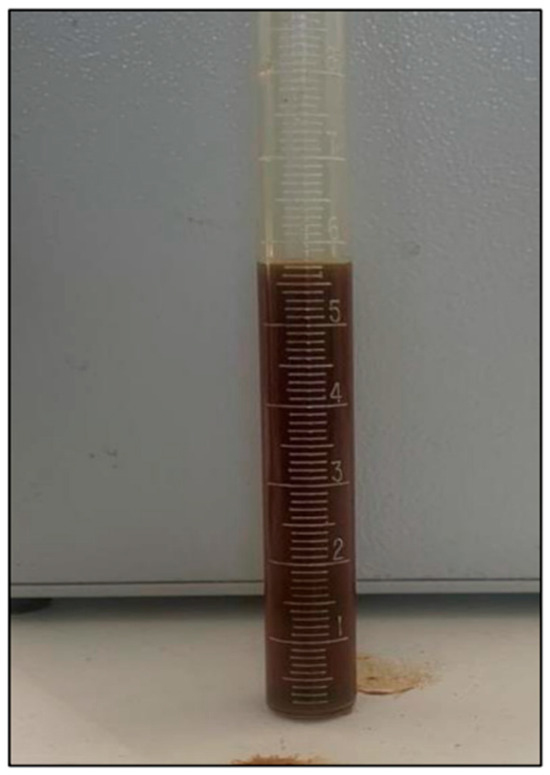
Figure 5.
Extracted oil and CO2 mixture after the experiment.
This hypothesis is substantiated by controlled experimental investigations conducted under supercritical CO2 conditions. In earlier investigations [25], mixed-layer illite–smectite clays were subjected to supercritical CO2 at 100 bar and 35 °C for durations ranging from 120 to 240 h. The study reported distinct shifts in X-ray diffraction patterns consistent with illite development, increases in illite-layer proportions, modifications in Brunauer–Emmett–Teller (BET) surface area, and evidence of mineral dissolution accompanied by secondary phase precipitation. These results demonstrate that incipient illitization and related mineralogical transformations can occur on short timescales under CO2 injection scenarios. Although the current study employed milder temperature and pressure conditions, the observed reduction in permeability and changes in elemental composition (as verified by SEM–EDS) are consistent with such reaction pathways, thereby reinforcing the interpretation of clay mineral alteration as a contributing factor to pore structure modification and flow impairment. SEM and EDS analyses confirmed the formation of secondary precipitates on pore surfaces, primarily composed of Fe, Na, and Cl compounds, which further reduced flow paths. The decrease in permeability (−19%) and porosity (−8%) is therefore attributed to a combination of physical compaction and geochemical transformations, particularly within clay-rich zones. These findings emphasize the importance of mineralogical composition in determining the outcomes of CO2-enhanced oil recovery processes. Figure 6 illustrates pore clogging observed by SEM before and after CO2 flooding. Table 4 and Table 5 show the elemental composition of particle surfaces, confirming the accumulation of Na, Cl, and Fe indicating salt precipitation. EDS (energy-dispersive X-ray spectroscopy) was used to determine the elemental composition of mineral surfaces.
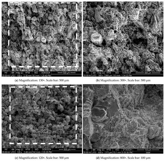
Figure 6.
SEM image of the sample: (a) Before the experiment with open pore spaces. General view of the sample fracture surface. The area outlined by the white line indicates the region analyzed using energy-dispersive X-ray spectroscopy (EDS). (b) After the experiment with clogged pores. (c) Particle surface after the experiment. (d) Pore space after the experiment.
Table 4.
Elemental composition (wt.%) of the particle surface after CO2 injection, obtained from EDS analysis at 1000× magnification.
Table 5.
Elemental composition (wt.%) of the clay-dominated zone on the particle surface after CO2 exposure, obtained from EDS analysis at 1000× magnification.
This study investigated pore structure modifications before and after CO2 injection. The core sample initially contained clay and carbonate cement, both of which underwent mineralogical alterations under CO2 exposure. The interaction between CO2 and the cementing materials led to severe pore clogging and a significant reduction in permeability. These findings highlight the critical role of mineral composition in CO2-induced reservoir transformations.
This study outlines a CO2-EOR testing procedure with pre-test rock characterization, reservoir condition simulation, and miscible CO2 injection under reservoir pressure and temperature. Experimental results based on the collected fluid composition showed that CO2 injection resulted in an increased oil recovery coefficient of −54%. However, the SEM and EDS results from the particle surfaces and pore space suggest induced structural modifications in reservoir rocks, impacting the reservoir properties of the formation rock. Permeability reduction around 19% resulted from the precipitation occurrence on the particle surface and clay mineral transformation. The porosity values also dropped by 8%, which along with the SEM and XRD analyses confirmed structural changes in pore networks due to CO2 injection.
Despite showing good results in terms of oil sweeping, poroperm parameter degradation requires further research. Future work should focus on screening optimal CO2-EOR candidates based on rock mineralogy and defining cutoff conditions to prevent cement bond alterations.
4. Simulation Study
Numerical simulation is a vital extension of laboratory experiments, allowing accurate prediction of reservoir-scale behavior of miscible CO2 injection under realistic geological settings. It bridges the gap between core-scale observations and field-scale application by incorporating multiphase flow physics, compositional effects, and reservoir heterogeneity. Additionally, simulation supports the optimization of injection strategies and enables long-term forecasting of oil recovery under various development scenarios [26].
CO2 injection into a sandstone reservoir was modeled, taking into account the complex multiphase flow phenomena, phase behavior, and compositional variations induced by CO2 interactions with reservoir fluids and rock. To capture these processes with high fidelity, the ECLIPSE E300 (2019.1) simulator was employed, given its robust capabilities for compositional and miscible gas injection modeling.
A single-porosity compositional model was employed, governed by mass conservation, Darcy’s law, and phase equilibrium equations. This framework provides a physically consistent representation of fluid transport and interaction within porous media.
To represent the physical heterogeneity of the MakXX field, a detailed three-dimensional sector model was constructed. The model captures the spatial variability of reservoir properties and fluid flow behavior with adequate resolution. The main parameters of the model are provided in Table 6.
Table 6.
The key specifications of the model.
To achieve the objectives of the study, a structured simulation workflow was implemented as follows:
- ✓
- Baseline reservoir conditions were established through initialization, ensuring accurate starting points for CO2 injection scenarios.
- ✓
- Laboratory measurements were used to calibrate model parameters. This step ensured alignment between simulated outputs and actual reservoir behavior.
- ✓
- Laboratory-derived fluid properties, core analysis, and PVT data were incorporated into the model to reflect realistic reservoir conditions and fluid responses to CO2 injection.
Figure 7 below presents the results of simulation calculations performed using T-Navigator software (2024, 24.1), illustrating the dynamics of daily oil production (ton/day) under two scenarios: with and without CO2 injection.
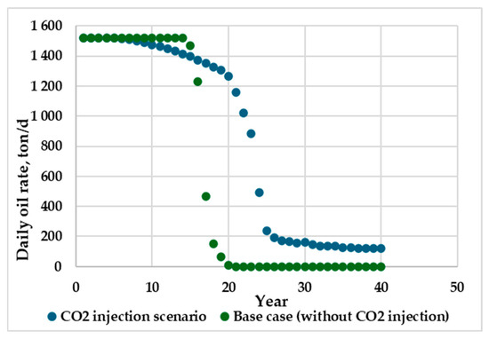
Figure 7.
Daily oil rate—CO2 vs. base case.
The green curve represents the base case scenario without CO2 injection, while the blue curve corresponds to the case with CO2 injection. Both curves illustrate the daily oil production rate (ton/day) over time.
Initially, oil production rates in both scenarios are comparable, reaching approximately 1500 tons/day. However, as production continues, a notable divergence is observed: the base case exhibits a sharp decline in oil production, whereas the CO2-injected case demonstrates a more gradual decrease.
This behavior indicates that CO2 injection contributes to production stabilization and slows the decline rate in oil output. Despite the overall downward trend in production, the implementation of miscible CO2-EOR results in more sustained oil recovery over time. These findings confirm the effectiveness of CO2 injection in enhancing oil recovery and improving reservoir performance compared to natural depletion.
The simulation results clearly demonstrate that miscible CO2 injection contributes to the stabilization of oil production and slows the rate of decline in comparison to natural depletion. While both scenarios exhibit an overall downward trend, the CO2-injected case maintains a more gradual reduction in oil output, thereby extending the effective production period and improving long-term recovery performance.
The consistency between simulation outcomes and laboratory results—specifically the replicated 54% oil recovery—provides strong validation of the physical mechanisms involved in miscible CO2-EOR. This agreement underscores the scalability of experimental observations and supports the robustness of the calibrated model (Figure 8).
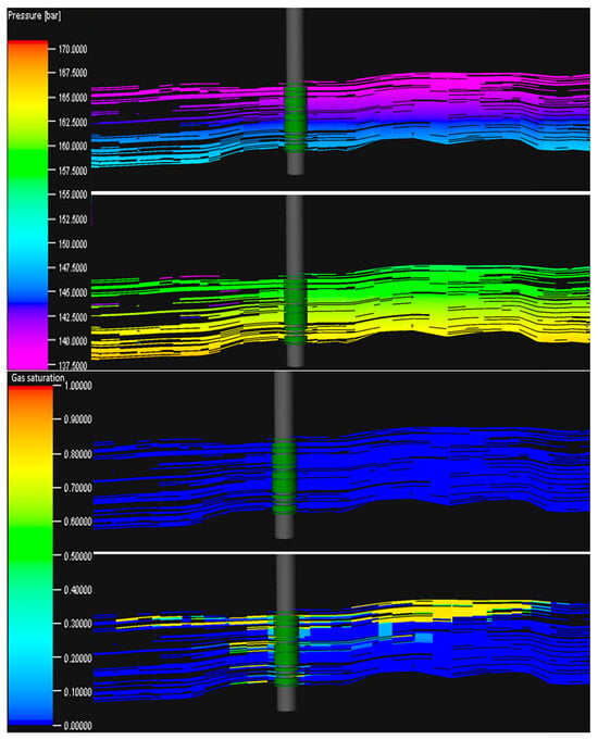
Figure 8.
Pressure and gas saturation evolution after 10 years.
Furthermore, the smoother decline in daily production observed in the CO2-injected scenario suggests a more efficient volumetric sweep and uniform displacement front, which can be attributed to the reduction in oil viscosity and interfacial tension characteristic of miscible conditions. Such behavior supports the hypothesis that CO2-EOR mechanisms established at core scale—such as enhanced mobility and improved contact efficiency—can be reliably upscaled to reservoir dimensions.
Figure 8 illustrates the spatial distribution of pressure and gas saturation after 10 years of simulation for both the base case and the CO2-injected scenario. The left panels show reservoir pressure evolution, while the right panels depict gas saturation. In the CO2-injected case, pressure distribution remains more uniform and elevated around the injection well, indicating effective pressure support and delayed reservoir depletion. This sustained pressure regime is critical for maintaining favorable displacement gradients during oil mobilization.
The gas saturation maps reveal a clear advancement of the CO2 front into the reservoir matrix. Notably, higher gas saturation is observed along the central flow paths, reflecting efficient miscible displacement and volumetric sweep. In contrast, the base case (without injection) exhibits a decline in pressure and a lack of gas-phase propagation, leading to reduced sweep efficiency and early water breakthrough.
These simulation outcomes confirm that CO2 injection enhances both areal and vertical sweep efficiency by stabilizing pressure and promoting uniform displacement. As a result, the mobility ratio improves, residual oil saturation decreases, and production decline slows. The synergy between laboratory observations (e.g., 54% oil recovery under miscible core flooding) and simulation data underscores the robustness of the proposed EOR approach and its applicability for field-scale deployment in heterogeneous reservoirs with moderate clay content.
In addition to the base case comparison, pressure sensitivity analysis was conducted to examine how deviations from the estimated MMP influence displacement performance. To assess the impact of injection pressure variation around the estimated minimum miscibility pressure (MMP), a sensitivity analysis was conducted using the compositional model. Simulations were performed at 12 MPa (sub-MMP), 13 MPa (baseline), and 14 MPa (above-MMP) to evaluate oil recovery performance. The results showed that oil recovery efficiency decreased by approximately 7–9% under sub-MMP conditions (12 MPa), indicating incomplete miscibility. At 14 MPa, displacement efficiency improved slightly compared to the baseline, but the risk of CO2 channeling and early breakthrough increased. These findings highlight the importance of accurate MMP determination and the need to carefully balance pressure selection in CO2-EOR design.
In summary, the integration of laboratory experiments and calibrated numerical simulation demonstrates that miscible CO2-EOR is a technically sound and scalable method for increasing oil recovery in the MakXX reservoir. These results substantiate the potential for field-scale application and provide a reliable foundation for designing and optimizing pilot CO2 injection schemes in clay-rich, heterogeneous siliciclastic reservoirs.
5. Conclusions
This study demonstrated the potential of miscible CO2-enhanced oil recovery (CO2-EOR) using reservoir core samples from the MakXX oilfield in southeastern Kazakhstan. Core flooding experiments under near-miscible conditions resulted in a 54% oil recovery efficiency. However, structural analysis revealed a 19% reduction in permeability and an 8% decline in porosity, attributed to mineralogical alterations such as clay transformation and carbonate precipitation. These findings highlight the dual impact of CO2-EOR: improved hydrocarbon recovery coupled with potential reservoir degradation. While the tested core is composed primarily of quartz–albite sandstone, the observed mechanisms—such as clay transformation and secondary mineral precipitation—are also relevant in clay- and carbonate-containing formations. Thus, while direct extrapolation to carbonate reservoirs is limited, the results can inform preliminary screening and modeling efforts in similar heterogeneous systems.
Simulation results based on a calibrated reservoir model confirmed that miscible CO2 injection enhances oil recovery and delays production decline, aligning well with laboratory observations. The consistency between core-scale experiments and field-scale modeling validates the applicability of CO2-EOR in the MakXX reservoir.
Future research should address the identified limitations by expanding the experimental dataset, incorporating mineralogical screening, and developing mitigation strategies to ensure reservoir integrity during large-scale CO2-EOR deployment.
Author Contributions
Conceptualization, A.B.N. and A.D.S.; Methodology, Y.R.S. and A.A.K.; Software, A.T.Z.; Formal analysis, A.B.N. and A.A.K.; Investigation, Y.R.S. and A.D.S.; Resources, R.B.M. and Y.R.S.; Data curation, R.B.M. and A.T.Z.; Writing—original draft, A.B.N.; Writing—review & editing, A.B.N.; Supervision, A.A.K. and A.D.S.; Project administration, A.A.K.; Funding acquisition, A.A.K. All authors have read and agreed to the published version of the manuscript.
Funding
This research was funded by Ministry of Science and Higher Education of the Republic of Kazakhstan, grant number AP19576974.
Data Availability Statement
The original contributions presented in this study are included in the article. Further inquiries can be directed to the corresponding author.
Conflicts of Interest
Ainur B. Niyazbayeva was employed by the company JSC “Kalamkas-Khazar Operating”. Rinat B. Merbayev was employed by the company KazMunayGas Engineering. The remaining authors declare that the research was conducted in the absence of any commercial or financial relationships that could be construed as a potential conflict of interest. The company had no role in the design of the study; in the collection, analyses, or interpretation of data; in the writing of the manuscript, or in the decision to publish the results.
References
- Massarweh, O.; Abushaikha, A.S. A Review of Recent Developments in CO2 Mobility Control in Enhanced Oil Recovery. Petroleum 2021, 8, 291–317. [Google Scholar] [CrossRef]
- Bealessio, B.A.; Alonso, N.A.B.; Mendes, N.J.; Sande, A.V.; Hascakir, B. A Review of Enhanced Oil Recovery (EOR) Methods Applied in Kazakhstan. Petroleum 2021, 7, 1–9. [Google Scholar] [CrossRef]
- Zhong, H.; Shi, B.; Bi, Y.; Cao, X.; Zhang, H.; Yu, C.; Tang, H. Interaction of Elasticity and Wettability on Enhanced Oil Recovery in Viscoelastic Polymer Flooding: A Case Study on Oil Droplet. Geoenergy Sci. Eng. 2025, 250, 213827. [Google Scholar] [CrossRef]
- Shabdirova, A.; Kozhagulova, A.; Samenov, Y.; Merbayev, R.; Niyazbayeva, A.; Shabdirov, D. Core Flooding Experiments on the Impact of CO2-EOR on the Petrophysical Properties and Oil Recovery Parameters of Reservoir Sandstones in Kazakhstan. Geosciences 2024, 14, 185. [Google Scholar] [CrossRef]
- Izgec, O.; Demiral, B.; Bertin, H.; Trefle, L.; Akin, S. CO2 Injection in Carbonates. In Proceedings of the SPE Western Regional Meeting, Irvine, CA, USA, 30 March–1 April 2005. [Google Scholar]
- Bachu, S. Identification of Oil Reservoirs Suitable for CO2-EOR and CO2 Storage (CCUS) Using Reserves Databases, with Application to Alberta, Canada. Int. J. Greenh. Gas Control. 2016, 44, 152–165. [Google Scholar] [CrossRef]
- Abuov, Y.; Serik, G.; Lee, W. Techno-Economic Assessment and Life Cycle Assessment of CO2-EOR. Environ. Sci. Technol. 2022, 56, 8571–8580. [Google Scholar] [CrossRef]
- Fath, A.H.; Pouranfard, A.-R. Evaluation of Miscible and Immiscible CO2 Injection in One of the Iranian Oil Fields. Egypt. J. Pet. 2014, 23, 255–270. [Google Scholar] [CrossRef]
- Gozalpour, F.; Ren, S.R.; Tohidi, B. CO2 EOR and Storage in Oil Reservoirs. Oil Gas Sci. Technol. Rev. IFP 2005, 60, 537–546. [Google Scholar] [CrossRef]
- Rufford, T.E.; Smart, S.; Watson, G.C.Y.; Graham, B.F.; Boxall, J.; Diniz da Costa, J.C.; May, E.F. The Removal of CO2 and N2 from Natural Gas: A Review of Conventional and Emerging Process Technologies. J. Pet. Sci. Eng. 2012, 94–95, 123–154. [Google Scholar] [CrossRef]
- Dong, Z.; Zhang, M.; Li, W.; Wen, F.; Dong, G.; Zou, L.; Zhang, Y. Development of a Predictive Model for Carbon Dioxide Corrosion Rate and Severity Based on Machine Learning Algorithms. Materials 2024, 17, 4046. [Google Scholar] [CrossRef]
- Rezaee, R.; Saeedi, A.; Iglauer, S.; Evans, B. Shale Alteration after Exposure to Supercritical CO2. Int. J. Greenh. Gas Control. 2017, 62, 91–99. [Google Scholar] [CrossRef]
- Khather, M.; Saeedi, A.; Myers, M.B.; Verrall, M. An Experimental Study for Carbonate Reservoirs on the Impact of CO2-EOR on Petrophysics and Oil Recovery. Fuel 2019, 235, 1019–1038. [Google Scholar] [CrossRef]
- Alvarado, V.; Manrique, E. Enhanced Oil Recovery: An Update Review. Energies 2010, 3, 1529–1575. [Google Scholar] [CrossRef]
- Krevor, S.; Pini, R.; Benson, S.M. Measurement of the Multiphase Flow Properties of the CO2/Brine System for Carbon Sequestration. Energy Procedia 2013, 37, 4499–4503. [Google Scholar] [CrossRef]
- He, H.; Ma, X.; Lei, F.; Liu, X.; Jiang, M.; Li, Y.; Mou, J. An Experimental Investigation of Interaction between CO2 Solution and Rock under Reservoir Conditions in the Jimsar Shale Oil Formation. Processes 2024, 12, 673. [Google Scholar] [CrossRef]
- Li, Q.; Li, Q.; Wang, F.; Xu, N.; Wang, Y.; Bai, B. Settling Behavior and Mechanism Analysis of Kaolinite as a Fracture Proppant of Hydrocarbon Reservoirs in CO2 Fracturing Fluid. Colloids Surf. A Physicochem. Eng. Asp. 2025, 724, 137463. [Google Scholar] [CrossRef]
- Qingchao, L.; Jingjuan, W.; Qiang, L.; Fuling, W.; Cheng, Y. Sediment Instability Caused by Gas Production from Hydrate-Bearing Sediment in Northern South China Sea by Horizontal Wellbore: Sensitivity Analysis. Nat. Resour. Res. 2025, 34, 1667–1699. [Google Scholar] [CrossRef]
- Bulekbayev, Z.E.; Iskuzhiyev, B.A.; Kamalov, S.M. Oil and Gas Fields of Kazakhstan: A Catalogue, 3rd ed.; Kazhegeldin, A.M., Ed.; Kazakhstan Mineral Resources: Almaty, Kazakhstan, 2016. [Google Scholar]
- Cronquist, C. Carbon Dioxide Dynamic Miscibility with Light Reservoir Oils. In Proceedings of the 4th Annual U.S. DOE Symposium, Tulsa, OK, USA, 29–31 August 1978. [Google Scholar]
- Li, H.; Qin, J.; Yang, D. An Improved CO2-Oil Minimum Miscibility Pressure Correlation for Live and Dead Crude Oils. Ind. Eng. Chem. Res. 2012, 51, 3516–3523. [Google Scholar] [CrossRef]
- Orr, F.M., Jr.; Jensen, C.M. Interpretation of Pressure-Composition Phase Diagrams for CO2/Crude-Oil Systems. Soc. Pet. Eng. J. 1984, 24, 485–497. [Google Scholar] [CrossRef]
- Bondarenko, A.V.; Islamov, S.R.; Ignatyev, K.V.; Mardashov, D.V. Laboratory Studies of Polymer Compositions for Well-Kill under Increased Fracturing. Perm J. Pet. Min. Eng. 2020, 20, 37–48. [Google Scholar] [CrossRef]
- Speight, J.G. CHAPTER 5—Exploration and General Methods for Oil Recovery. In Enhanced Recovery Methods for Heavy Oil and Tar Sands; Speight, J.G., Ed.; Gulf Publishing Company: Houston, TX, USA, 2009; pp. 133–184. ISBN 978-1-933762-25-8. [Google Scholar]
- Martín, D.; Aparicio, P.; García, S.; Maroto-Valer, M.M. Mixed-Layer Illite-Smectite Illitization under Supercritical CO2 Conditions. Appl. Sci. 2022, 12, 11477. [Google Scholar] [CrossRef]
- Zholdybayeva, A.; Syzdykov, A.; Pourafshary, P.; Ismailova, J.; Delikesheva, D. Importance of Clay Swelling on the Efficacy of Cyclic Steam Stimulation in the East Moldabek Formation in Kazakhstan. Energies 2024, 17, 5078. [Google Scholar] [CrossRef]


Disclaimer/Publisher’s Note: The statements, opinions and data contained in all publications are solely those of the individual author(s) and contributor(s) and not of MDPI and/or the editor(s). MDPI and/or the editor(s) disclaim responsibility for any injury to people or property resulting from any ideas, methods, instructions or products referred to in the content. |
© 2025 by the authors. Licensee MDPI, Basel, Switzerland. This article is an open access article distributed under the terms and conditions of the Creative Commons Attribution (CC BY) license (https://creativecommons.org/licenses/by/4.0/).