Abstract
With growing demand for high-performance and high-efficiency motors, Axial Flux Permanent Magnet Motors (AFPMs) have received significant attention. These motors typically use rare-earth magnets due to their high magnetic and energy density. However, rare-earth magnets face challenges such as limited availability and price volatility, prompting research into reducing magnet usage. This study aims to reduce magnet consumption by applying a Consequent Pole (CP) structure to AFPMs. While CP structures improve magnet efficiency, they also introduce significant back-EMF ripple. To address this, an Intersect Consequent Pole (ICP) structure is proposed, which reduces ripple through alternating magnet placement within the rotor. Since ICP implementation is difficult in single-rotor AFPMs, a double-rotor, single-stator configuration was used. Simulation results show that the proposed design effectively reduces magnet usage and back-EMF ripple, demonstrating its potential for maintaining high performance with reduced rare-earth dependency.
Keywords:
motor; axial flux motor; AFM; AFPM; cogging torque; torque ripple; consequent pole; magnet using 1. Introduction
Among various types of motors, the two most representative categories are the Radial Flux Permanent Magnet Motor (RFPM) and the Axial Flux Permanent Magnet Motor (AFPM). These classifications are based on the direction of the magnetic flux generated by the permanent magnets. Due to its various advantages, AFPMs have been widely studied for applications in home appliances, defense industries, and hybrid electric vehicles [1,2,3,4,5]. The key benefits of AFPMs include a compact structure, high torque and power density, low maintenance, and high efficiency. However, to achieve high torque and power density, AFPMs typically require magnets containing rare-earth elements [6,7,8]. These materials are associated with high costs and supply chain vulnerabilities due to their limited reserves and heavy reliance on imports. Therefore, this study focuses on reducing the magnet usage while maintaining the same performance level. To this end, the Consequent Pole (CP) structure is applied to the AFPM motor [9,10,11,12,13,14,15]. While the use of CPs can effectively reduce magnet consumption, it also introduces several drawbacks. In conventional motors, applying a CP structure leads to asymmetric magnet placement, resulting in unbalanced back electromotive force (back-EMF) and increased ripple components, which cause undesirable noise and vibration. This study investigates an AFPM design intended for collaborative robots, where minimizing noise and vibration is particularly critical. While the CP structure helps reduce magnet usage, it significantly increases ripple. To address this issue, we propose the Intersect Consequent Pole (ICP) structure. However, ICP can only be implemented in specific AFPM configurations. AFPM motors are available in various configurations, including single-stator/single-rotor, double-stator/single-rotor, single-stator/double-rotor, and multi-stator/multi-rotor types. ICP can only be applied to the double-rotor type, as this configuration allows for the implementation of opposing CPs on the upper and lower rotors, thereby compensating for the disadvantages of the conventional CP structure. In this study, we select the single-stator and double-rotor configuration for the AFPM. This configuration can be further categorized into NN-type and NS-type. While the overall performance difference between these two types is minimal, the NN-type generates significantly less ripple. Therefore, the NN-type is adopted. In the NN-type single-stator and double-rotor AFPM, both the upper and lower rotors include only N-pole magnets in a consequent pole configuration. This allows the ripple components generated by each rotor to cancel each other, thereby reducing total ripple. Moreover, the combined back-EMF from both rotors results in a more symmetrical waveform, effectively eliminating asymmetry issues.
Consequently, the proposed configuration resolves the major drawbacks of the conventional CP structure. Although magnet usage is reduced by approximately 50%, this leads to a reduction in magnetic loading and thus motor performance. To compensate, we increase the electric loading to maintain equivalent overall performance. Importantly, magnetic loading does not decrease in exact proportion to the magnet reduction, allowing the required increase in electric loading to be kept relatively low. Furthermore, the reduced magnetic loading results in lower flux density saturation in both the rotor and the stator. This enables the reduction of back yoke thickness and an increase in the number of turns per teeth, enhancing performance. In conclusion, the proposed ICP-based AFPM design achieves both magnet-usage reduction and ripple suppression without compromising motor size or performance, making it highly suitable for noise-sensitive applications such as collaborative robots.
2. Analysis of Conventional Models
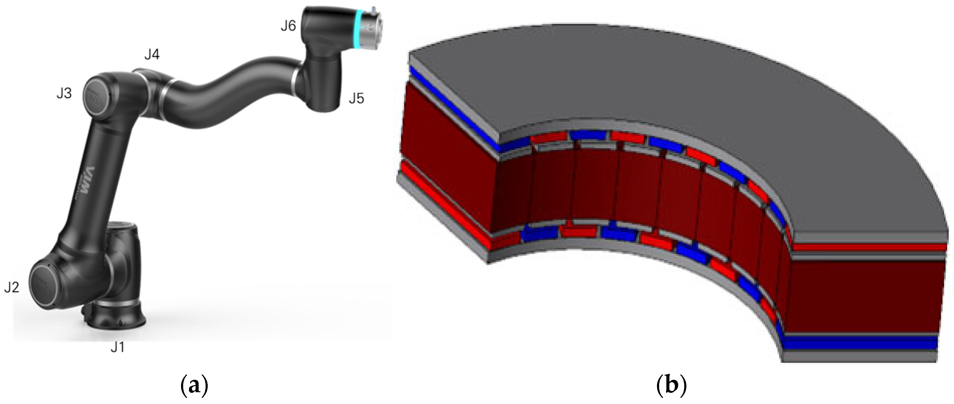
Figure 1 illustrates the structure of a collaborative robot. For the collaborative robot application, an axial flux motor was selected due to its advantages in thin, compact designs. A thin (or flat) structure refers to a motor configuration in which the stacking length is shorter than the outer diameter. The reason axial flux motors are well-suited for such thin structures can be understood by examining the torque equation. Equation (1) presents the torque equation for a radial flux motor.

Figure 1.
Collaborative robot and its dedicated motor: (a) Collaborative robot; (b) axial flux motor for collaborative robot applications.
In this equation, denotes the winding factor, is the average air-gap magnetic flux density, represents the specific electric loading, is the rotor diameter, and indicates the stack length. The torque of a radial flux motor is proportional to . Equation (2) presents the torque equation for an axial flux motor.
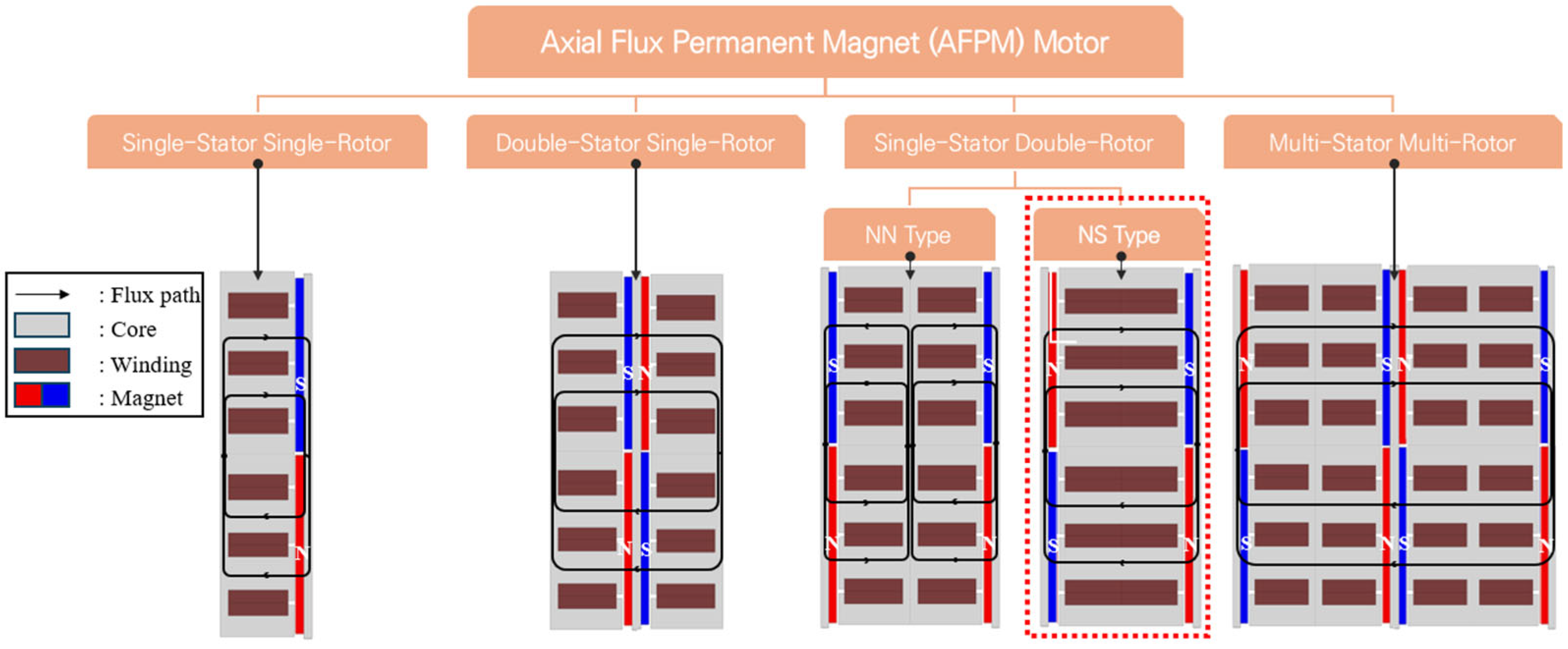
The torque of an axial flux motor is proportional to , where represents the rotor diameter. Unlike radial flux motors where the rotor diameter is not equal to the overall motor diameter in axial flux motors, the rotor diameter is equal to the motor diameter. This results in higher torque density. Moreover, since torque increases with the cube of the diameter in thin motor structures, axial flux motors are particularly advantageous for compact, flat designs. Various types of axial flux motors exist. Figure 2 illustrates several types of axial flux motor configurations. The most basic type is the single-stator, single-rotor structure, but other types can be classified based on the number of stators and rotors. In this study, the reference model employs a single-stator, double-rotor configuration. This type can be further divided into two subtypes: the NN-type and the NS-type. The reference motor used in this paper corresponds to the NS-type. Figure 1b shows the structure of the single-stator, double-rotor axial flux motor designed for collaborative robot applications. In the NS-type, the stator is located between the upper and lower rotors, and the magnetic polarities of the two rotors are opposite to each other.
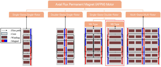
Figure 2.
Axial flux permanent magnet motor type.
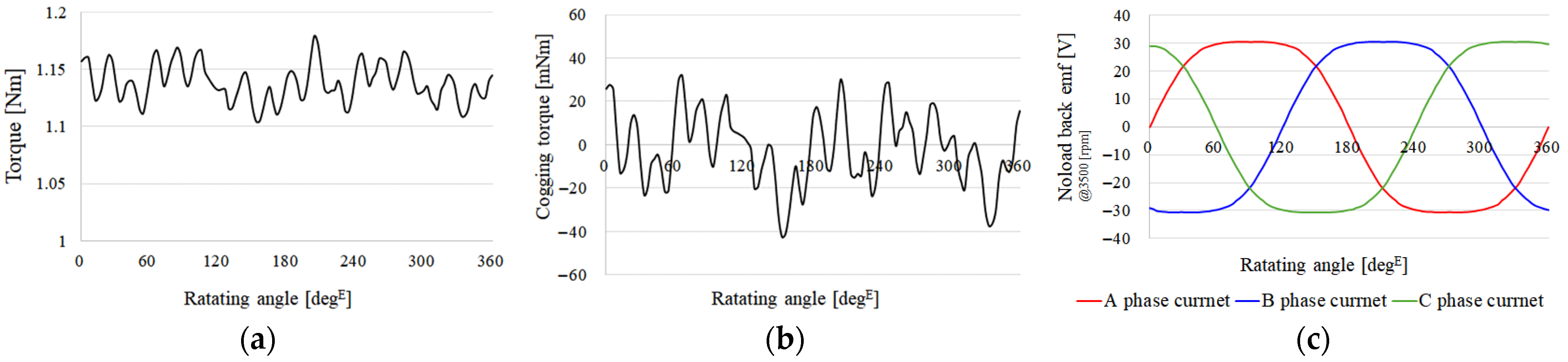
Table 1 shows the specifications and materials of the existing models. Since the stator is significantly affected by core loss, Somaloy material was used to reduce it. In contrast, the rotor rotates at synchronous speed, making it less susceptible to core loss. Additionally, to improve manufacturability, a solid core made of S45C steel was employed for the rotor. Motors used in collaborative robots must operate smoothly. Therefore, it is essential to minimize ripple components, which can cause vibration and interfere with precise motion control. In electric motors, ripple components include cogging torque, which appears under no-load conditions, and torque ripple, which occurs under load. For collaborative robot applications, both cogging torque and torque ripple must be minimized to ensure smooth and stable operation. Figure 3 shows the load and no-load torque waveforms, as well as the no-load back-EMF waveform of the reference model. Table 2 summarizes the key performance metrics of the motor.

Table 1.
The specifications of the reference motor.
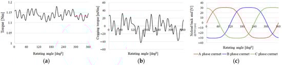
Figure 3.
Main performance characteristics of the baseline model: (a) torque; (b) cogging torque; (c) no-load back electromotive force (EMF).
Table 2.
Performance of the reference model.
The performance of the conventional model shows that both torque ripple and cogging torque are relatively low. However, it exhibits a high core loss. This study aims to reduce the motor’s ripple characteristics and magnet usage, and further, to achieve a reduction in core loss as well.
3. Consequent Pole Structure of a Dual-Rotor Type Axial Flux Motor
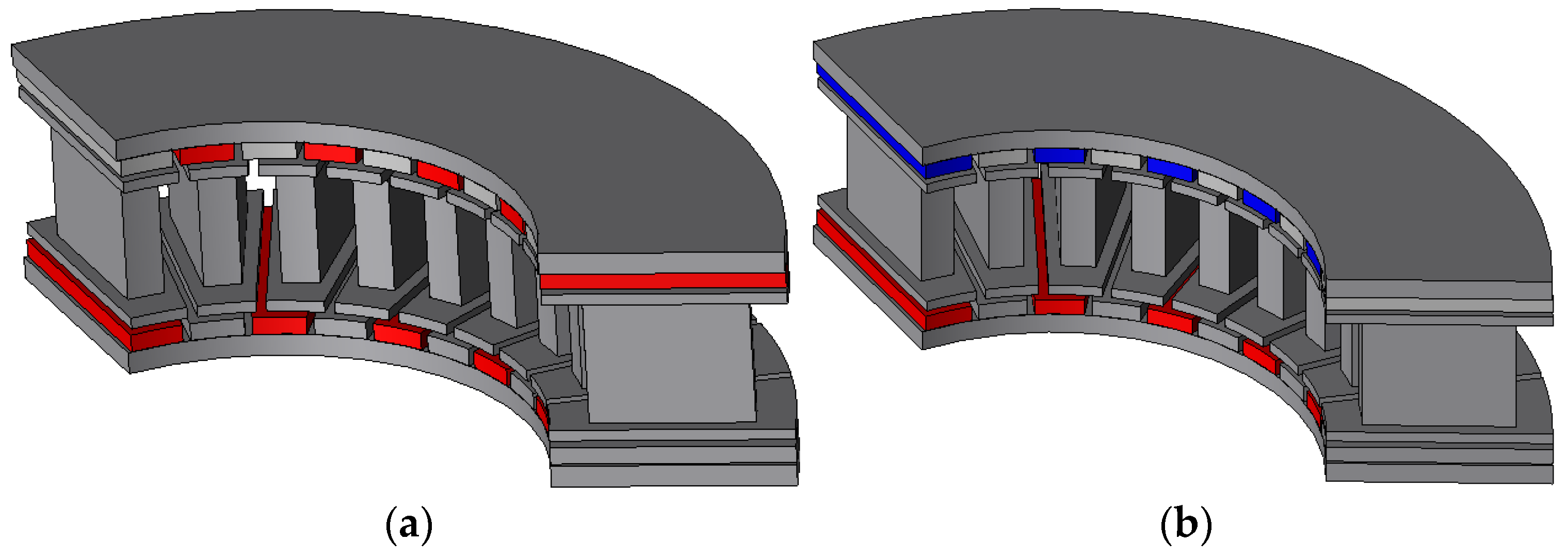
In this study, a consequent pole (CP) structure is applied to an axial flux motor (AFM). The CP structure uses only one magnetic pole, where one side consists of a permanent magnet and the other side is replaced by iron. This configuration can reduce magnet usage by approximately 50%. However, when the CP structure is applied to a radial flux motor or a basic axial flux motor (e.g., single-rotor, single-stator type), several drawbacks occur. First, ripple components such as torque ripple and cogging torque significantly increase. This is because a motor using full-pole magnets has symmetrical magnetic characteristics, whereas the CP structure, which consists of a magnet on one side and iron on the other, introduces asymmetry. As a result, ripple components are amplified. Additionally, asymmetry in the back electromotive force (back-EMF) also arises. In collaborative robot applications, ripple components are critical; thus, a conventional CP structure is generally not suitable. However, a dual-rotor, single-stator type AFM can overcome these limitations. This is because it allows for a symmetrical arrangement of the CP structure on the upper and lower rotors, balancing the magnetic effects and mitigating the ripple increase. Figure 4 illustrates the symmetrical CP configuration applied to a dual-rotor, single-stator type axial flux motor.
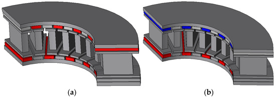
Figure 4.
Consequent pole structure of a dual-rotor, single-stator type AFM: (a) NN-type configuration; (b) NS-type configuration.
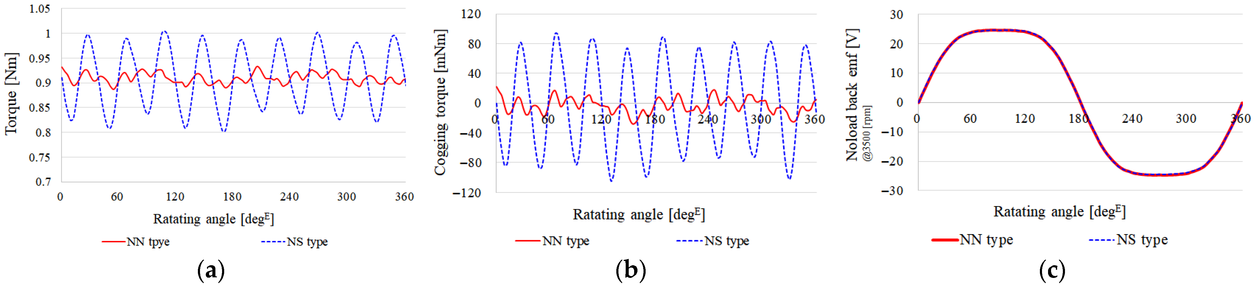
Figure 4a shows the consequent pole NN-type of a dual-rotor, single-stator axial flux motor (AFM), and Figure 4b illustrates the consequent pole NS-type configuration. In these figures, the N-pole is defined as the direction in which magnetic flux enters the stator, while the S-pole indicates the direction in which magnetic flux exits the stator. In the NN-type configuration, both the upper and lower rotors consist of N-pole magnets and iron segments. The magnets and iron pieces are arranged to face each other across the stator, allowing a proper magnetic flux path to be established. In the NS-type configuration, the upper and lower rotors consist of N-pole and S-pole magnets, respectively, with iron segments facing each other. This configuration also ensures a continuous magnetic flux path between the rotors through the stator. Figure 5 presents the key performance results for the two consequent pole types applied to the dual-rotor, single-stator AFM. In this analysis, all motor parameters remain identical to the reference model, except that the permanent magnets were selectively replaced with iron segments to evaluate the impact of the consequent pole configuration.
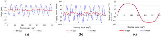
Figure 5.
Performance comparison between NN-type and NS-type: (a) torque; (b) cogging torque; (c) no-load back-EMF.
Table 3 presents the key performance metrics of the NN-type and NS-type consequent pole configurations in the dual-rotor, single-stator axial flux motor (AFM). The overall performance of both types was found to be similar. However, there were significant differences in ripple-related characteristics, specifically in torque ripple and cogging torque. The NS-type exhibited higher ripple components compared to the NN-type. This is attributed to the structural asymmetry in the NS-type configuration. While the NN-type has magnets arranged in an alternating pattern across the upper and lower rotors, the NS-type has magnets on one rotor facing iron segments on the other, creating an asymmetrical magnetic distribution. In the NN-type, the upper rotor has a magnet–iron alternating pattern, and the lower rotor follows a magnet–iron sequence in reverse. This configuration causes the ripple components generated by the upper and lower rotors to partially cancel each other, resulting in reduced overall ripple. Therefore, this study selects the NN-type configuration for the consequent pole structure in the dual-rotor, single-stator AFM, as it provides superior performance in terms of ripple suppression.
Table 3.
Performance comparison between NN-type and NS-type.
4. Consequent Pole NN-Type of a Dual-Rotor Axial Flux Motor
In this study, the consequent pole structure of the dual-rotor type axial flux motor (AFM) was designed with an intersected configuration, which is hereafter referred to as the ICP-AFM (Intersect Consequent Pole Axial Flux Motor). Table 4 presents the key performance metrics of the ICP-AFM with the NN-type configuration.
Table 4.
Main performance of ICP-AFM NN-type.
When comparing the reference model and the ICP-AFM with NN-type, the no-load back-EMF decreased from 24.6 Vrms to 19.97 Vrms, representing a reduction of 18.82%, and the torque decreased from 1.01 Nm to 0.79 Nm, a 21.8% reduction. However, the magnet usage in the ICP-AFM NN-type was reduced by 50% compared to the reference model. In terms of ripple-related performance, the torque ripple decreased from 74.74 mNm to 46.01 mNm, a 38.45% reduction, and the cogging torque was reduced from 74.65 mNm to 49.04 mNm, corresponding to a 34.36% decrease. Additionally, the core loss was reduced from 46.33 W to 31.9 W, showing a 31.14% improvement. However, the rotor back yoke eddy current loss increased significantly, from 1.6 W to 7.44 W. This increase is due to the replacement of magnets with iron material (S45C) in the consequent pole regions, which leads to additional eddy current loss in the rotor back yoke. Although the magnet volume in the ICP-AFM NN-type is reduced by 50%, the magnet eddy current loss remains comparable to that of the reference model. This is because the magnetic flux variation in the magnets is greater in the consequent pole structure. Despite the performance reductions, the ICP-AFM NN-type offers significant advantages in terms of material efficiency and ripple suppression. To further analyze and compensate for performance differences, the magnetic saturation levels of both models were investigated.
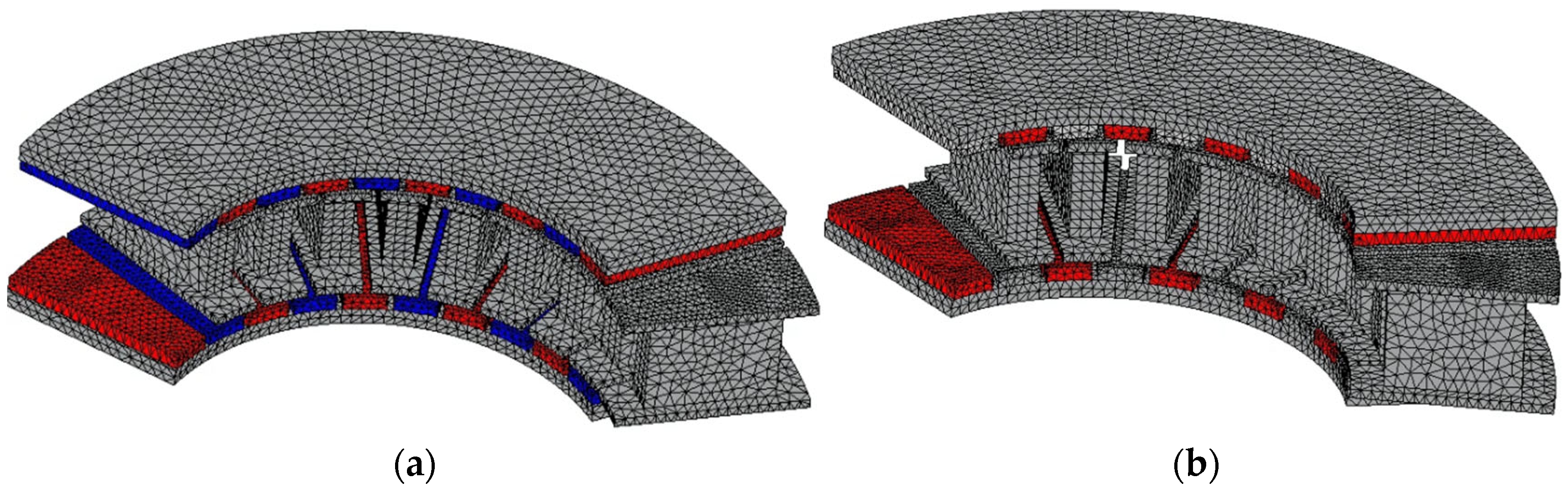
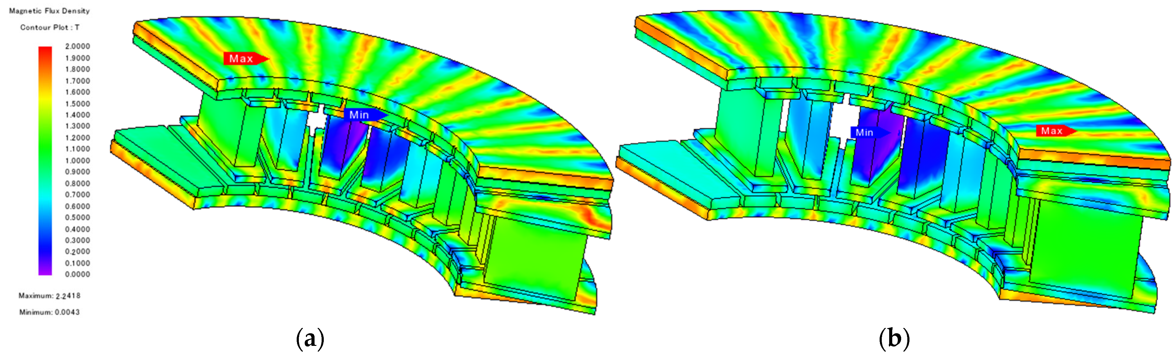
Figure 6 shows the saturation comparison between the reference model and the ICP-AFM NN-type. In addition, Figure 7 shows the FEA simulation mesh configurations for both models. The analysis was conducted using a similar number of mesh elements for a fair comparison.
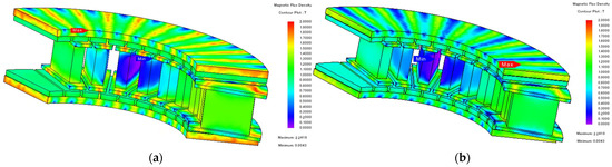
Figure 6.
Magnetic flux density distribution: (a) reference model; (b) ICP-AFM.
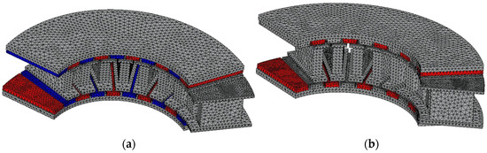
Figure 7.
Finite Element Analysis (FEA) mesh: (a) reference model; (b) ICP-AFM.
The ICP-AFM uses 50% less magnet material compared to the reference model, which results in a lower magnetic flux density saturation. To match the performance of the reference model, several design strategies can be considered. The first approach is to increase the magnet thickness, since the magnetic flux density in the rotor back yoke is lower than that of the reference model. By increasing the magnet thickness, the ICP-AFM—despite using less magnet material overall—can recover the required performance level with only a slight increase in magnet usage. The second approach involves reducing the teeth width, thereby allowing a greater number of turns per teeth, which leads to an increase in electric loading to compensate for the performance drop. In this study, the first approach was investigated first. This decision was based on the fact that, in the reference motor, the core loss is greater than the copper loss, making it more effective to pursue a design strategy that increases electric loading rather than further increasing current. Because the magnetic flux density in the ICP-AFM is lower than in the reference model, the rotor back yoke and teeth thickness were reduced to raise the magnetic loading back to comparable levels. This design change also increases slot area, which enables more turns per teeth, thereby increasing electric loading. Figure 7 shows the variation in back-EMF with respect to different rotor back yoke and slot thickness values.
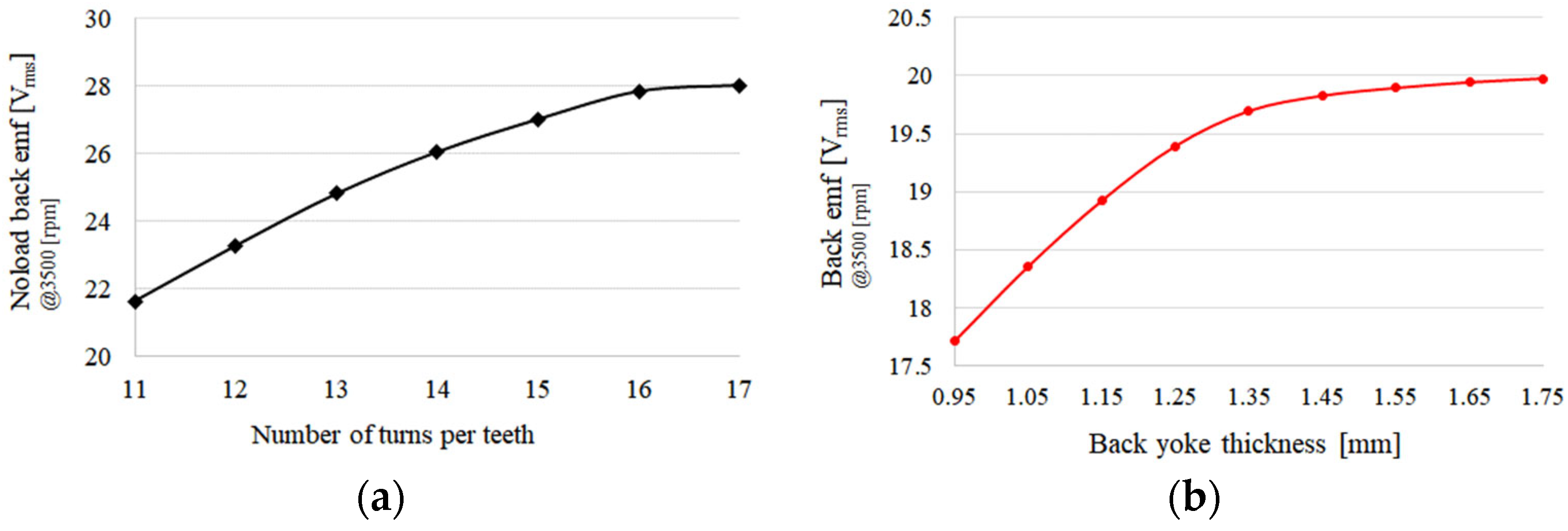
Figure 8a shows the variation of back-EMF with respect to the number of turns per teeth. As the slot thickness increases, the teeth width decreases, leading to magnetic saturation in the teeth. As a result, a decreasing trend in back-EMF is observed. This analysis was performed under the condition of a constant number of turns per teeth. Figure 8b presents the relationship between rotor back yoke thickness and back-EMF, with the back yoke thickness varied from 0.95 mm to 1.75 mm. As the rotor back yoke becomes thinner, the teeth length increases, which in turn enlarges the slot area, allowing for higher electric loading. It was observed that magnetic saturation begins to occur around 1.25 mm to 1.35 mm back yoke thickness. Based on this trend, the slot thickness and rotor back yoke thickness should be carefully selected. Referring to Figure 6b, the rotor back yoke thickness was set to 1.35 mm. Reducing the back yoke thickness increases the stator slot area, which leads to a decrease in the fill factor. To ensure equivalent performance compared to the reference model, the fill factor and current density were maintained at the same level. For a fair comparison under the same fill factor, the same wire diameter as the reference model was used, and the number of turns per teeth was increased while expanding the slot area accordingly. Figure 8a also shows the no-load back-EMF as a function of the number of turns per teeth under the condition of a constant fill factor. As the number of turns per teeth increases, the no-load back-EMF also increases. However, because the teeth width decreases with more turns, magnetic saturation under load conditions may occur, potentially degrading performance. Therefore, it is important to optimize the teeth thickness. From Figure 8b, it was confirmed that at 13 turns per teeth, the same performance as the reference model can be achieved, and the final design was set to 13 turns. Although increasing the number of turns per teeth leads to higher electric loading and thus greater copper loss, the reference model has dominant core loss. Therefore, this design approach slightly increases copper loss while significantly reducing core loss, resulting in improved overall efficiency.
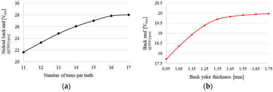
Figure 8.
Back-EMF variation according to key design parameters: (a) back-EMF versus number of turns per teeth, (b) back-EMF versus rotor back yoke thickness.
5. Magnetic Equivalent Circuit of the ICP-AFM NN-Type
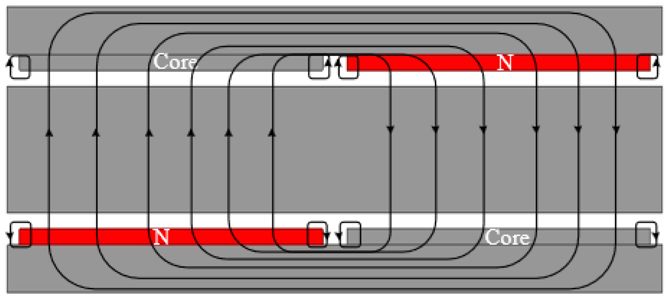
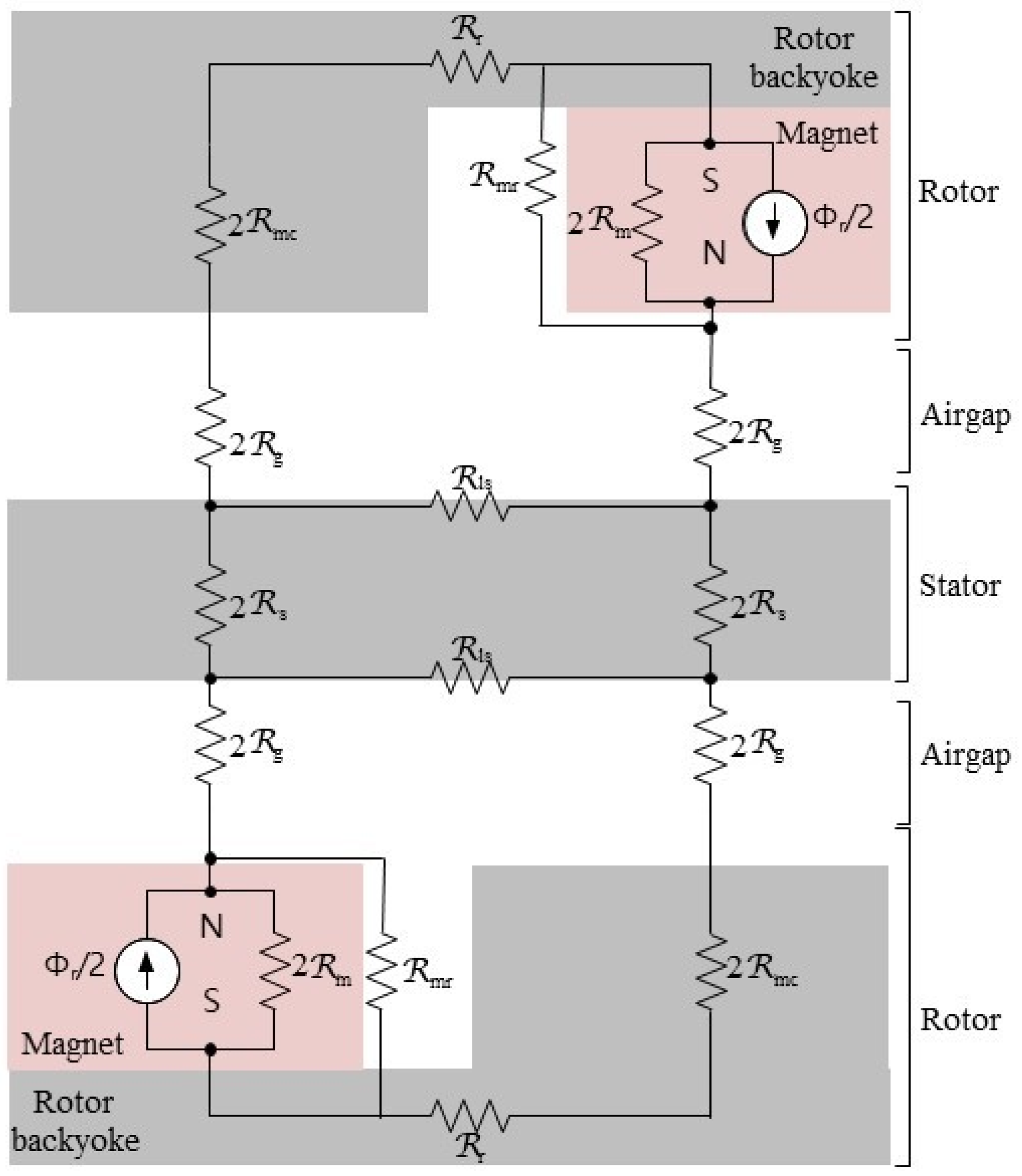
Figure 9 illustrates the magnetic flux diagram of the dual-rotor ICP-AFM. As shown in the diagram, the magnetic flux originating from the N-pole follows two distinct paths: one part passes through the stator and links to the opposing S-pole, while the other part leaks through the air gap, bypassing the stator, and connects to the adjacent S-pole. Due to the symmetrical configuration of the structure, it can be assumed that the flux emanating from one pole splits evenly, with a portion entering the adjacent pole. This symmetrical flux distribution ensures a balanced magnetic circuit within the motor. Figure 10 presents the magnetic equivalent circuit, modeled based on half of one magnetic pole. In this equivalent circuit, the magnetomotive force (MMF) generated by the windings is neglected, and only the passive magnetic components are considered.
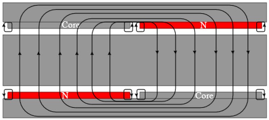
Figure 9.
Magnetic flux path of the consequent pole structure.

Figure 10.
Magnetic equivalent circuit of the ICP-AFM.
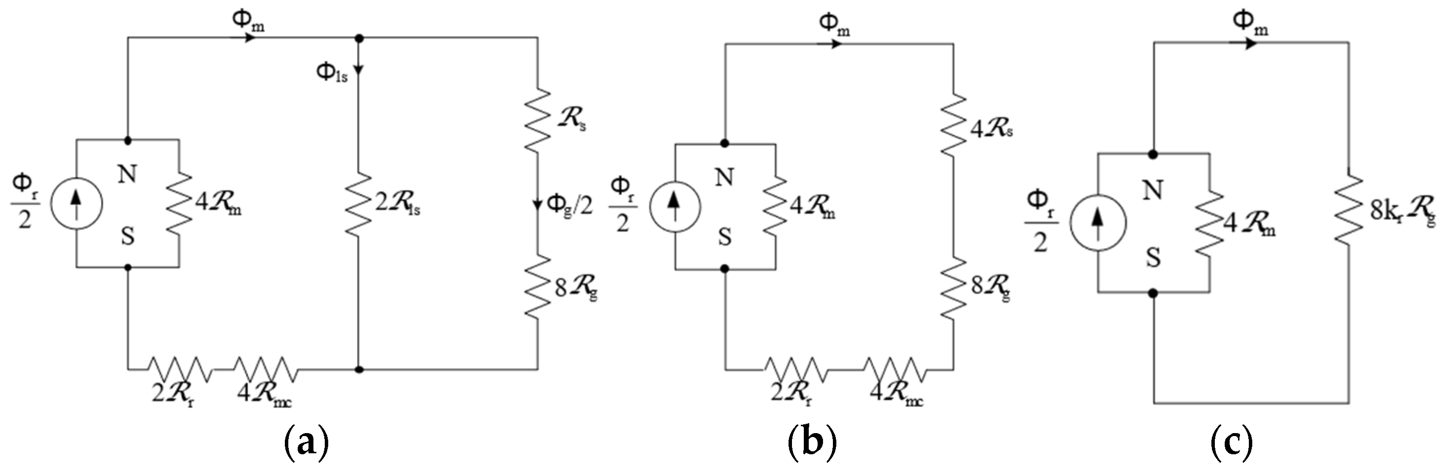
In Figure 10, the permanent magnet is modeled as a Norton equivalent magnetic flux source, representing half of the flux produced by a single magnet pole as . The magnetic reluctance of the permanent magnet is expressed as 2. In the magnetic equivalent circuit and represent the reluctance of the stator back yoke and rotor back yoke, respectively, while denotes the air-gap reluctance. The reluctance corresponds to the leakage reluctance, representing flux that does not link with the armature windings and instead leaks into adjacent or opposite poles. By simplifying the magnetic equivalent circuit shown in Figure 10, a more compact representation is illustrated in Figure 11. Furthermore, by introducing the leakage coefficient (), the circuit can be further simplified as shown in Figure 11b. Figure 12 presents the key rotor geometry parameters used in the equivalent circuit model. The leakage coefficient ( is always less than 1, as it accounts for the proportion of magnetic flux generated by the permanent magnet that leaks through the air gap and does not link with the intended magnetic path. This leakage coefficient can be defined as follows:

Figure 11.
Magnetic equivalent circuits of the ICP-AFM: (a) first simplified magnetic equivalent circuit of the ICP-AFM; (b) second magnetic equivalent circuit of the ICP-AFM; (c) third magnetic equivalent circuit of the ICP-AFM.

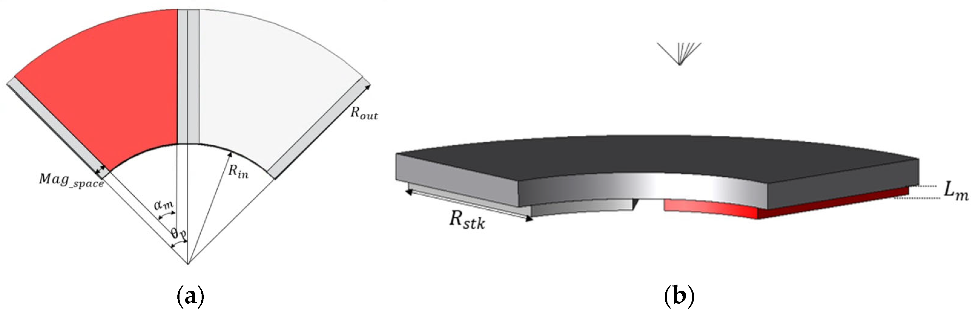
Figure 12.
Rotor geometry definition: (a) main variables of the rotor cross-section; (b) main variables of the rotor lamination structure.
The air-gap magnetic flux can be calculated using the leakage coefficient ( as follows:
Additionally, it is difficult to precisely calculate the magnetic reluctance of the core components, such as the rotor and stator iron cores. However, since the reluctance of the core is significantly smaller compared to that of the air gap, the circuit can be further simplified using a reluctance coefficient, as shown in Figure 11c.
Finally, using the fully simplified magnetic equivalent circuit, the magnetic flux generated by the permanent magnet can be calculated as follows:
Here, the magnetic reluctance of the permanent magnet and the air gap can be calculated as follows:
Here, is the magnet thickness in the stacking direction, is the effective air-gap length, is the cross-sectional area of the permanent magnet, and is the effective air-gap area per pole. These parameters can be used to compute the reluctances as follows. In this context, denotes the Carter coefficient.
Here, is defined as the average radius between the inner and outer radii of the axial permanent magnet. is defined as the radial length of the motor, calculated by subtracting the inner radius from the outer radius. The term refers to the spacing between magnets, which is determined based on the selected pole arc ratio. In the case of axial flux motors, accurately determining the magnet width is challenging because, unlike in radial SPM motors, the inner and outer arc lengths of the magnets differ due to their circular geometry. To address this, a practical approach is adopted: a reference radius defined at one-quarter of the radial length from the inner radius. Using this intermediate radius, the effective magnet width can be estimated, as illustrated in Figure 13.

Figure 13.
No-load magnetic saturation comparison between the conventional and final models: (a) conventional model; (b) final model.
Based on the relationship between magnetic flux density and magnetic flux, the air-gap magnetic flux density can be expressed as follows:
The air-gap magnetic flux density is defined as the average flux density considering only the vertical (normal) component of the magnetic flux derived earlier. Accordingly, the magnitude of the fundamental wave of the air-gap magnetic flux density can be calculated as follows:
The equation for the air-gap magnetic flux density represents the average flux density considering only the normal (vertical) component of the previously derived magnetic flux. Therefore, the magnitude of the fundamental component of the air-gap magnetic flux density can be calculated as follows:
The magnetic flux per pole can be calculated using the magnitude of the fundamental component of the air-gap magnetic flux density, as follows:
Finally, the linkage magnetic flux generated by the permanent magnet can be calculated as follows:
A comparative analysis was performed between the simulation data and the analytical calculation results. Table 5 presents a comparison between the simulation data and the calculated values. The comparison between the FEA simulation results and the MEC (magnetic equivalent circuit) calculations showed an error rate of approximately 1.2%, confirming the validity and accuracy of the calculated values.
Table 5.
A comparison between simulated and theoretical results.
6. Performance Analysis of the Final Model
For the final model development, it is essential to perform not only no-load analysis but also load analysis. Under load conditions, the magnetic flux density in the core becomes a critical design parameter when current is applied. If the magnetic flux density is too high, magnetic saturation may occur, adversely affecting performance. No-load analysis results showed that applying the consequent pole structure leads to a reduction in no-load back-EMF. To maintain equivalent performance, the teeth and slot widths were reduced to increase the slot area. The expanded slot area allows for a greater number of turns per teeth, which enhances the motor’s performance. The design was carried out under the same current density and fill factor conditions as the reference model. To improve performance, the number of turns per teeth was increased from 10 to 13. Figure 12 illustrates the magnetic saturation distributions of the two models.
As shown in Figure 13, the magnetic saturation levels of the conventional model and the final model are observed to be similar. These findings provide indirect evidence that the iron-related heat and eddy current losses are minimal. Table 6 summarizes the key performance metrics of both the conventional and final models.
Table 6.
Main performance comparison between the conventional and final models.
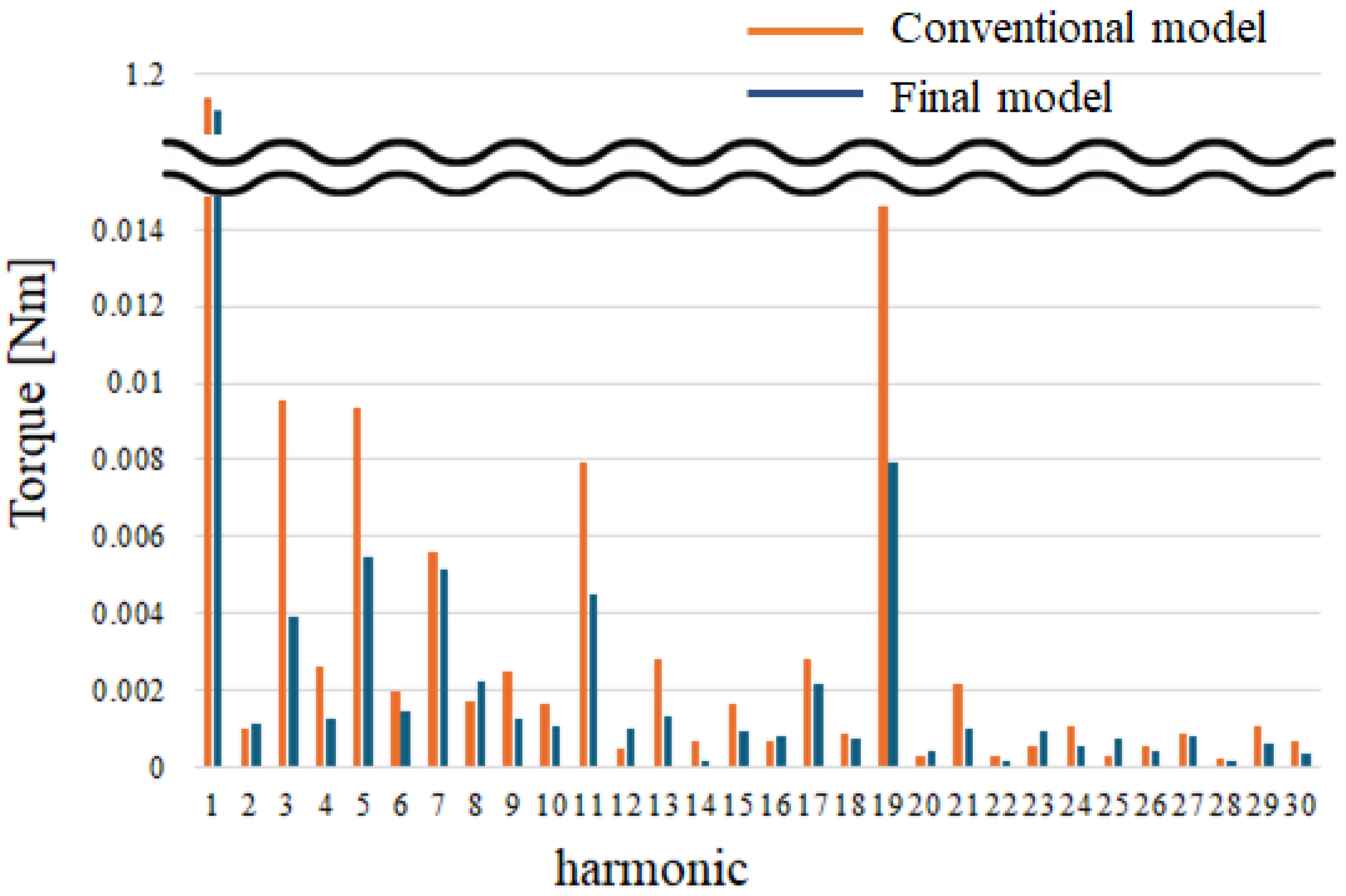
As shown in Table 6, the conventional model and the final model exhibit comparable performance. The no-load back-EMF and torque values are similar between the two models. However, differences are observed in terms of losses, output power, and efficiency. Losses are primarily categorized into core loss and eddy current loss. In this study, core eddy current loss refers to the eddy current loss generated in components made of S45C material, such as the rotor back yoke or magnet regions that have been replaced with core material in the ICP structure. The core loss of the conventional model is 46.33 W, whereas the final model achieves a reduced value of 34.97 W, representing a 24.5% reduction. However, the core eddy current loss increased significantly from 1.16 W to 7.16 W, which is approximately a 6.2-fold increase. As a result, the total core-related losses decreased from 60.19 W to 56.78 W, showing an overall 5.66% reduction. The copper loss increased slightly, from 12.08 W to 14.05 W, which is an approximate 1.5% increase. Nevertheless, due to the overall decrease in total losses, the efficiency improved from 86.12% to 86.78%. This improvement is mainly attributed to the reduction in rotor back yoke and teeth thickness in the final model, which helped lower core losses. Although additional coil turns were required leading to a slight increase in copper loss the increase in coil length was limited due to the reduced teeth width. As a result, the rise in copper loss was minimal. Finally, a harmonic analysis of the torque waveform was performed using FFT (Fast Fourier Transform). The torque harmonics are illustrated in Figure 13.
As shown in Figure 14, the final model with the consequent pole structure exhibits lower overall torque harmonics compared to the conventional model. In particular, the 3rd-, 5th-, 11th-, and 19th-order harmonics are significantly reduced. As a result, the electromagnetic vibration of the final model is effectively suppressed.

Figure 14.
Torque harmonic spectrum.
7. Results
This study focuses on the design and analysis of a motor for collaborative robot applications. To achieve high power density, an axial flux motor (AFM) was selected. Among various AFM configurations, the single-stator, double-rotor type was chosen for its structural advantages. In collaborative robot motors, cogging torque and torque ripple are critical factors affecting smooth motion and precise control. To address this, a consequent pole (CP) structure was proposed for the single-stator, double-rotor AFM. Two types of CP configurations were considered: NN-type and NS-type. In the NS-type, magnets and cores are aligned across the two rotors, leading to increased cogging torque and torque ripple. In contrast, the NN-type features alternating magnets and cores across the rotors, resulting in more uniform magnetic force distribution and thus reduced cogging torque and torque ripple. However, applying the intersect consequent pole (ICP) structure reduces magnet usage by 50%, which inherently decreases performance. To compensate, a design strategy was implemented to increase electric loading and restore performance to the level of the reference model. As a result, under equivalent performance conditions, the core loss was reduced from 46.33 W to 34.97 W (24.5%), while the core eddy current loss increased from 1.16 W to 7.16 W (6.2 times) due to the use of S45C material. The copper loss also increased slightly from 12.08 W to 14.05 W. Despite this, the total loss decreased, leading to an efficiency improvement from 86.12% to 86.78%, a gain of 0.68 percentage points. In conclusion, the proposed design achieves equivalent performance with a 50% reduction in magnet usage and a 0.68 percentage point improvement in efficiency, making it a promising solution for collaborative robot motor applications.
Author Contributions
Conceptualization, S.-W.S. and W.-H.K.; Methodology, S.-W.S. and W.-H.K.; Validation, S.-W.S., S.-H.L. and W.-H.K.; Formal analysis, S.-W.S.; Investigation, S.-W.S. and S.-H.L.; Data curation, S.-W.S.; Writing—original draft, S.-W.S.; Writing—review and editing, S.-W.S.; Visualization, S.-H.L.; Supervision, W.-H.K.; Project administration, S.-W.S. and W.-H.K.; Funding acquisition, W.-H.K. All authors have read and agreed to the published version of the manuscript.
Funding
This work was supported by the Technology Innovation Program (No. 2410000834), Development of industrial DC servo motor technology of 750W. In part, this research was funded by the Korea Institute of Energy Technology Evaluation and Planning (KETEP) and the Ministry of Trade, Industry & Energy (MOTIE) of the Republic of Korea (No. RS-2023-00232767).
Data Availability Statement
The original contributions presented in this study are included in the article. Further inquiries can be directed to the corresponding author.
Conflicts of Interest
The authors declare no conflict of interest.
References
- Polat, M.; Yildiz, A.; Akinci, R. Performance Analysis and Reduction of Torque Ripple of Axial Flux Permanent Magnet Synchronous Motor Manufactured for Electric Vehicles. IEEE Trans. Magn. 2021, 57, 8106809. [Google Scholar] [CrossRef]
- Kim, K.; Hwang, M.; Kim, H.K.D.; Cha, H. Torque Improvement and Magnetic Flux Leakage Reduction in Interior Permanent Magnet Axial Flux Motors with Flux Barrier Structure. IEEE Access 2024, 12, 150869–150879. [Google Scholar] [CrossRef]
- Fan, W.; Quan, L.; Zhu, X.; Xu, L.; Fan, D. Electromagnetic Performance Analysis of an Axial Flux Partitioned Stator Hybrid-Excited Less-Rare-Earth PM Synchronous Motor. IEEE Trans. Appl. Supercond. 2020, 30, 5203905. [Google Scholar] [CrossRef]
- Bauer, A.; Dieterich, D.; Urschel, S. Comparison of Eddy Current Loss Calculation Techniques for Axial Flux Motors with Printed Circuit Board Windings. Energies 2025, 18, 2603. [Google Scholar] [CrossRef]
- Guo, M.; Xia, J.; Wu, Q.; Gao, W.; Qiu, H. Study on Length–Diameter Ratio of Axial–Radial Flux Hybrid Excitation Machine. Processes 2024, 12, 2942. [Google Scholar] [CrossRef]
- Komlev, A.S.; Gimaev, R.R.; Davydov, A.S.; Zverev, V.I. The influence of chemical impurities on the properties of heavy rare-earth metals (Tb, Dy, Ho): Experimental and theoretical approaches. Materialia 2021, 18, 101166. [Google Scholar] [CrossRef]
- Kim, B.-C.; Lee, J.-H.; Kang, D.-W. A Study on the Effect of Eddy Current Loss and Demagnetization Characteristics of Magnet Division. IEEE Trans. Appl. Supercond. 2020, 30, 600805. [Google Scholar] [CrossRef]
- Jeong, G.; Kim, H.; Lee, J. A Study on the Design of IPMSM for Reliability of Demagnetization Characteristics-Based Rotor. IEEE Trans. Appl. Supercond. 2020, 30, 5204805. [Google Scholar] [CrossRef]
- Cai, S.; Zhu, Z.-Q.; Wang, C.; Mipo, J.-C.; Personnaz, S. A Novel Fractional Slot Non-Overlapping Winding Hybrid Excited Machine with Consequent-Pole PM Rotor. IEEE Trans. Energy Convers. 2020, 35, 1628–1637. [Google Scholar] [CrossRef]
- Li, Y.; Yang, H.; Lin, H.; Ding, S.; Hang, J.; Li, W. Influences of Magnet Arrangements on Air-Gap Field Modulation Effects in Interior Consequent-Pole PM Machines. IEEE Trans. Transp. Electrif. 2023, 9, 819–832. [Google Scholar] [CrossRef]
- Jo, C.; Yun, I.; Hong, H.; Lee, J.; Kim, H. Asymmetric Design of Consequent Pole to Reduce Torque Ripple. IEEE Trans. Magn. 2024, 60, 8204905. [Google Scholar] [CrossRef]
- Hsieh, M.-F.; Chang, C.-Y.; Huynh, T.-A.; Dorrell, D.G. Design and Analysis of Consequent-Pole Permanent Magnet Vernier Motor with Cancellation of Even-Order Harmonics. IEEE Trans. Magn. 2023, 59, 8204406. [Google Scholar] [CrossRef]
- Yang, K.; Zhao, F.; Wang, Y.; Bao, Z. Consequent-Pole Flux Reversal Permanent Magnet Machine with Halbach Array Magnets in Rotor Slot. IEEE Trans. Magn. 2021, 57, 8100905. [Google Scholar] [CrossRef]
- Zheng, Y.; Zhu, Z.Q.; Liang, D.; Xu, H.; Zhou, Y.; Liu, H.; Chen, L. Analysis and Reduction of Unipolar End Leakage Flux in Consequent-Pole PM Machines. IEEE Trans. Ind. Appl. 2025, 61, 196–208. [Google Scholar] [CrossRef]
- Zheng, Y.; Xiang, W.; Xu, H.; Tan, P.; Fang, Y. Analysis of a Flux Reversal Machine with Consequent-Pole Evenly Distributed PM. IEEE Trans. Ind. Appl. 2024, 60, 4–11. [Google Scholar] [CrossRef]

Disclaimer/Publisher’s Note: The statements, opinions and data contained in all publications are solely those of the individual author(s) and contributor(s) and not of MDPI and/or the editor(s). MDPI and/or the editor(s) disclaim responsibility for any injury to people or property resulting from any ideas, methods, instructions or products referred to in the content. |
© 2025 by the authors. Licensee MDPI, Basel, Switzerland. This article is an open access article distributed under the terms and conditions of the Creative Commons Attribution (CC BY) license (https://creativecommons.org/licenses/by/4.0/).