Abstract
With the increasing depth of mining operations, roadways experience higher ground stress and pronounced deformation. Elevated in situ stress leads to a continuous rise in vertical stress on surrounding rock. The excavation of roadways and working faces further redistributes the stress field, resulting in more frequent and severe floor heave. To address this issue in the 1232 transportation roadway of Shuguang Coal Mine, a numerical model was developed using the discrete element method (PFC2D) to systematically analyze the impacts of floor stiffness, strength, and joint distribution on heave mechanisms. A mechanical device for underground slotting operations was designed, and the optimal slotting depth was determined through simulation. The results indicate that floor heave stems from progressive failure of composite strata, governed by stiffness, strength, and moment of inertia (influenced by strata thickness and joint development). Effective suppression requires slotting depths to penetrate the shallow fractured zone and reach the load-bearing structure. Stress arching effects significantly mitigate deformation at 2.5 m depth, providing a theoretical basis for optimal slotting design.
1. Introduction
Statistics show that floor deformation control accounts for 65–70% of roadway surrounding rock stability management. Floor heave is one of the most common manifestations of floor failure. It not only narrows the roadway cross-section—hindering pedestrian access, transportation, and ventilation—but also compromises the stability and integrity of support systems, severely impacting safe mine operations [1]. Therefore, in depth investigation of the mechanisms of floor heave and its control methods holds significant theoretical and practical value for improving roadway floor stability. Numerous scholars, both domestic and international, have conducted extensive research on this issue. Kang et al. [2,3], He et al. [4,5,6], and others concluded that roadway floor heave is primarily caused by various mechanisms including elasto-plastic deformation, dilation, water-induced swelling, rheological behavior, and flexural fracturing of the floor strata. Li et al. [7] studied the stress distribution patterns in the surrounding rock of retreat roadways under mining influence using theoretical analysis and FLAC3D numerical simulation, focusing on the effect of different pillar widths and spacing. Indraratna [8] from Australia employed simulation software to analyze fracture development in the floor, providing valuable insights into the mechanisms and predictive modeling of crack propagation. Xu et al. [9], in response to floor heave deformation in Caojiatan Mine, developed a series of core technologies for roadway protection through roof cutting and pressure relief, based on detailed studies of overburden movement and coal seam variation. Song et al. [10] proposed mitigation measures for both reinforced and pressure-relief-type floor heave based on extensive field observations, theoretical analysis, and numerical simulations. Wang et al. [11] integrated practical engineering scenarios with floor heave mechanisms and proposed a terminal anchor cable bundle reinforcement method for floor stabilization using theoretical and numerical approaches. Zhu et al. [12], using the disturbed intake roadway in the west wing of Yuwu Coal Mine as the research context, proposed an optimized combined support system of “inverted U-shaped steel arches + grouted anchor bolts”, supported by theory and simulation. The scheme’s effectiveness was validated through industrial-scale trials. Li et al. [13] systematically examined the mechanisms of floor heave under mining disturbances and proposed a method combining floor slotting for pressure relief with additional bolt support at the base of both sidewalls. Guo et al. [14] demonstrated the effectiveness of slotting and pressure relief in controlling roadway floor heave. Their in depth analysis revealed that when the slotting depth exceeds 0.5 times the roadway width, the mitigation effect is significantly enhanced. Moreover, changes in slot angle alter the stress distribution in the floor, offering further control of floor deformation. Hou et al. [15] identified floor heave and creep as the two major challenges in enhancing roadway stability in underground coal mines, and proposed a technology to address both issues based on theoretical analysis. S. Mo [16] showed that floor bolts can effectively reduce surrounding rock deformation and thereby mitigate floor heave. Ren et al. [17] developed a novel block particle discrete element simulation method that matches the dual media of overlying rocks (OLR) and loose layers (LSL). Han et al. [18] studied the permeability characteristics of five sets of penetrating fractures (CPF) with different joint roughness coefficients (JRC). Based on 3D shape scanner testing and hydraulic coupling testing, the method of evaluating effective geometric parameters on the surface of the crack was improved under various constraint pressures, and the relationships between effective geometric parameters and constraint pressures were established. Zhang et al. [19] concluded that discrete element method (DEM) simulation is crucial for bridging macro and micro studies, summarized the research status, and discussed related issues. Han et al. [20] applied slotting pressure-relief techniques to control floor heave in deep, high-stress roadways. Their study revealed that a slotting depth of 2 m results in the most uniform heave distribution. Wei et al. [21] and others used FLAC3D simulation to investigate the deformation characteristics and energy transfer of the floor and surrounding rock after slotting in deep-buried roadways. Li et al. [22] addressed severe floor heave caused by the stress concentration and weak floor lithology using slotting pressure relief techniques. Zhou et al. [23] studied variations in stress distribution and the displacement of surrounding rock before and after slotting pressure relief through numerical simulation. Hao et al. [24] and colleagues validated the predictive reliability of their proposed model by comparing it with numerical simulation results. Many researchers have shifted from single-aspect approaches to comprehensive control strategies for managing large deformations in the rock surrounding roadways, and have successfully applied these solutions in real mining environments.
2. Project Overview
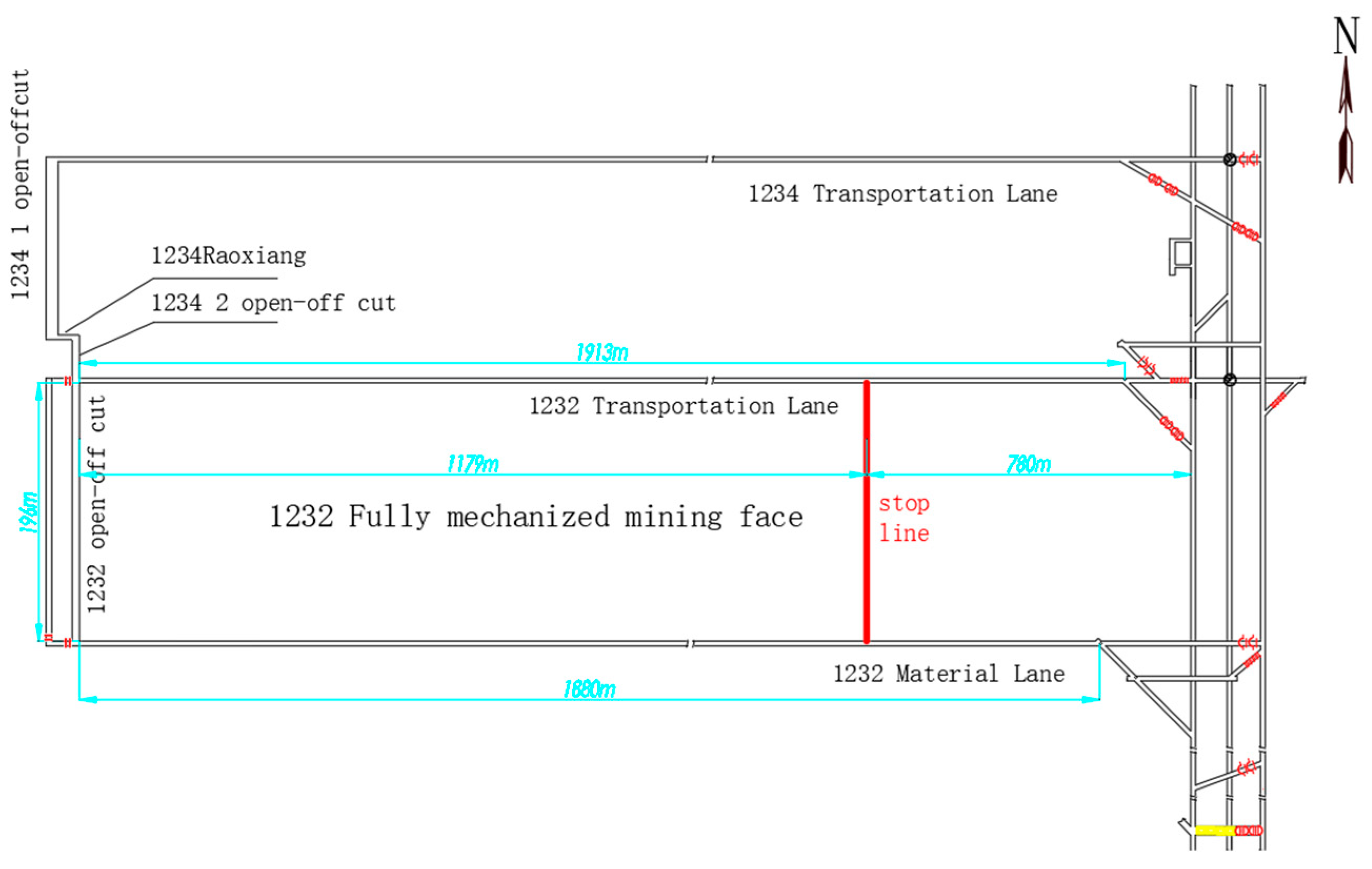
The fully mechanized mining face #1232 is located in the Loess Plateau region, characterized by low hills and beam-shaped loess tablelands. The surface elevation ranges from +951 m to +1142 m, resulting in a relative elevation difference of 91 m. The western boundary of the working face coincides with the edge of the mining district. To the east of the #1232 face lies the central track roadway; its western side borders the mine boundary. The southern side is adjacent to the active #1230 mining face, while the northern boundary connects to the yet-to-be-mined #1234 face. The mining layout of the working face is shown in Figure 1.
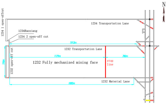
Figure 1.
Comprehensive mining face mining layout plan for #1232.
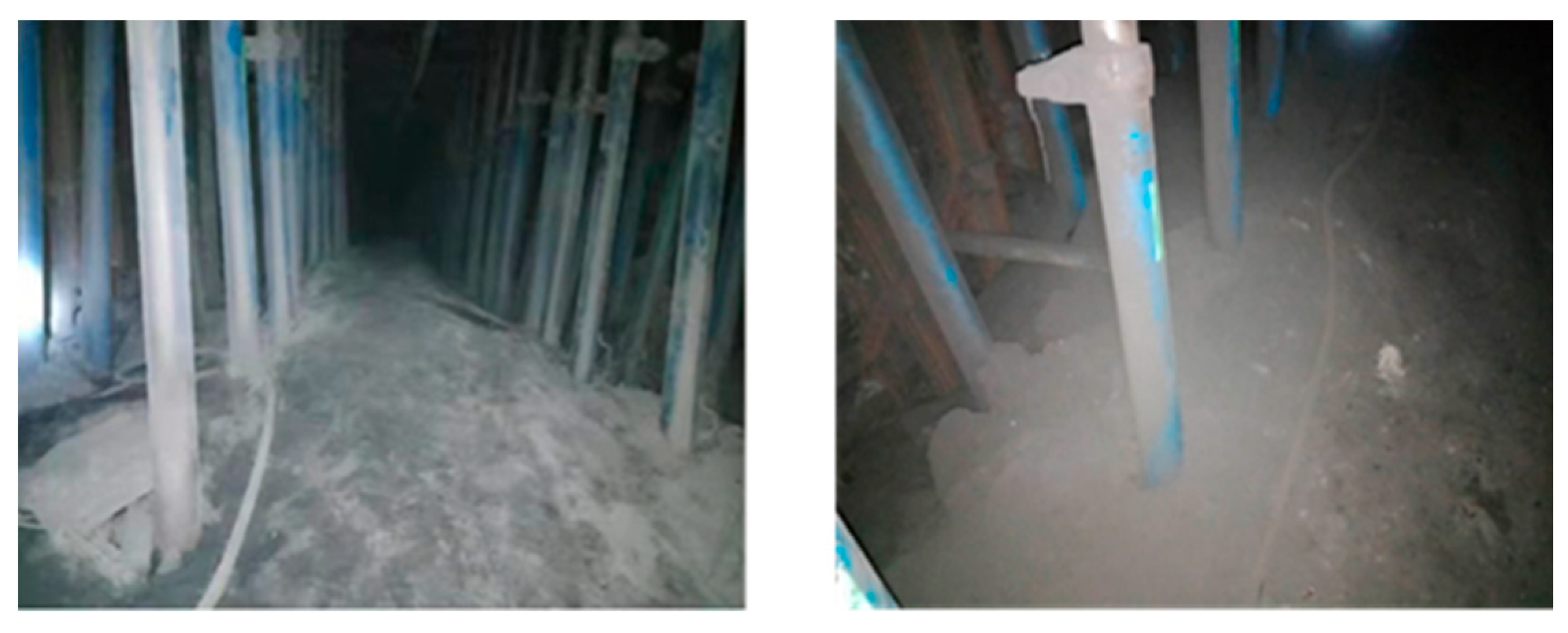
Shuguang Coal Mine currently extracts the No. 2 coal seam. The buried depth of coal seam No. 2 in 1232 Transportation Lane is greater than 600 m, which is considered a deep buried coal seam, where deformation of the roadway’s surrounding rock is predominantly characterized by floor heave. This issue has become more pronounced since the adoption of gob-side entry retaining without coal pillars, which has led to intensified deformation in the retained roadways. As a result, roadway reconstruction costs—such as bottom re-excavation and reinforcement support—have significantly increased. Additionally, the complexity of ensuring roadway stability has greatly increased, posing serious challenges to safe and efficient mine production. As shown in Figure 2, floor heave in the 1232 transportation roadway is evident, with a heave magnitude of no less than 30 cm.

Figure 2.
On site photo of the bottom drum in the roadway of Shuguang Coal Mine.
Mechanical Parameter Testing of Rock Surrounding the Roadway
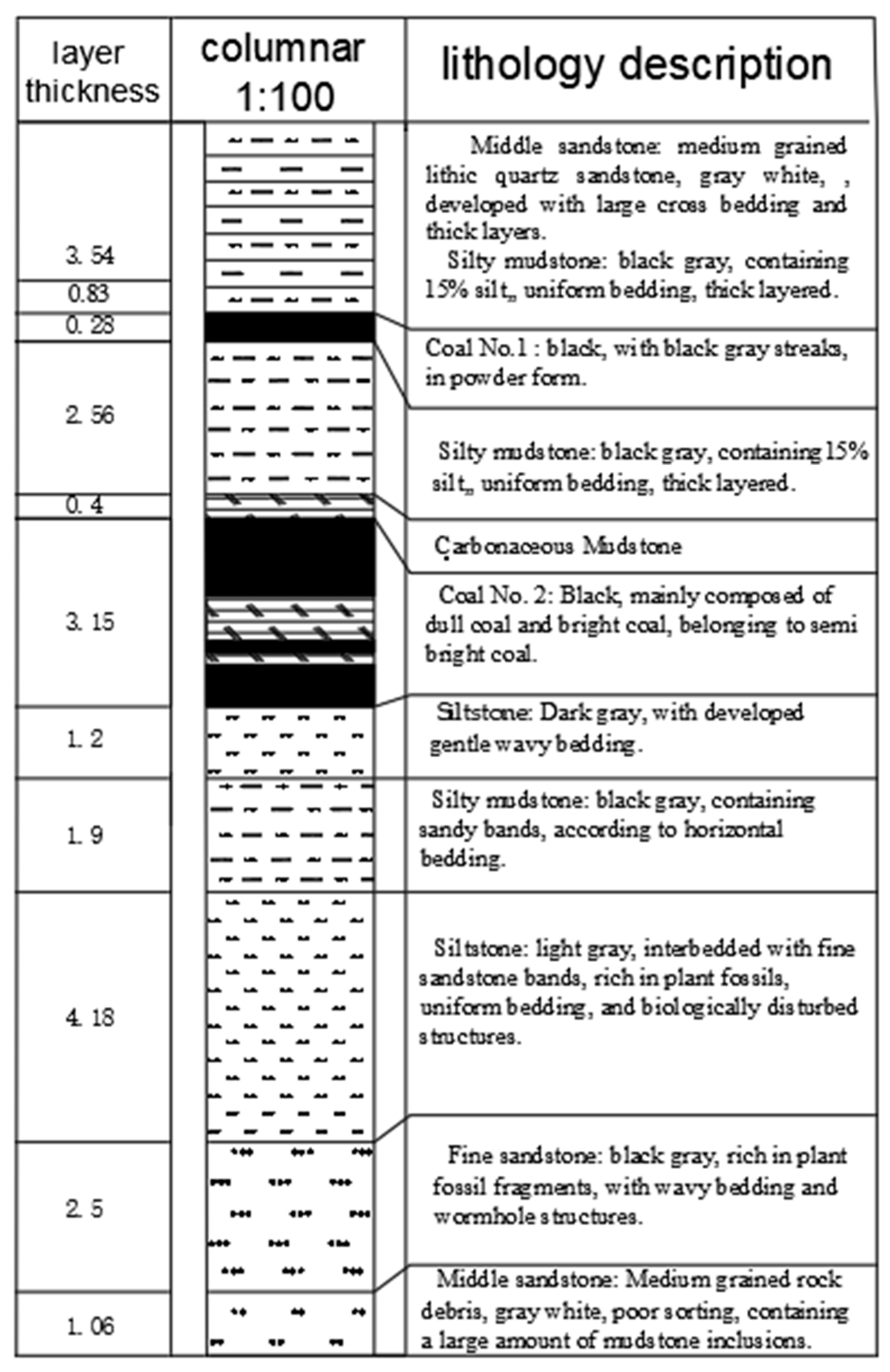
The determination of the physical and mechanical properties of rock forms the foundation of rock mass engineering analysis in mining. These test data serve not only as key indicators for rock mass quality classification systems but also as critical input parameters for constructing multi-scale models of rock mass stability. The experimental results indicate that parameters such as uniaxial compressive strength and Poisson’s ratio have a decisive influence on the design and control of rock surrounding a roadway. In view of the floor heave observed in the 1232 transportation roadway of the No. 2 coal seam at Shuguang Coal Mine, combined with the comprehensive bar chart of #1232 as shown in Figure 3, a study on control strategies was conducted. In agreement with the mine operator, core sampling for rock mechanical testing was carried out approximately 200 m from the roadway entrance. The physical and mechanical parameters of each rock stratum are listed in Table 1.

Figure 3.
Coal seam top and bottom slate layer column chart of 1232 Transportation Lane.

Table 1.
Physical and mechanical parameters of rock formations.
3. Discrete Element Analysis of Floor Heave Mechanism
3.1. Model Construction
Due to its depth (≈600 m) and structural background, vertical stress dominates in Shuguang Coal Mine. On site monitoring shows that vertical stress accounts for about 85% of the total stress concentration in the bottom strata. Therefore, this study considered vertical stress and applied horizontal displacement constraints to establish a model.
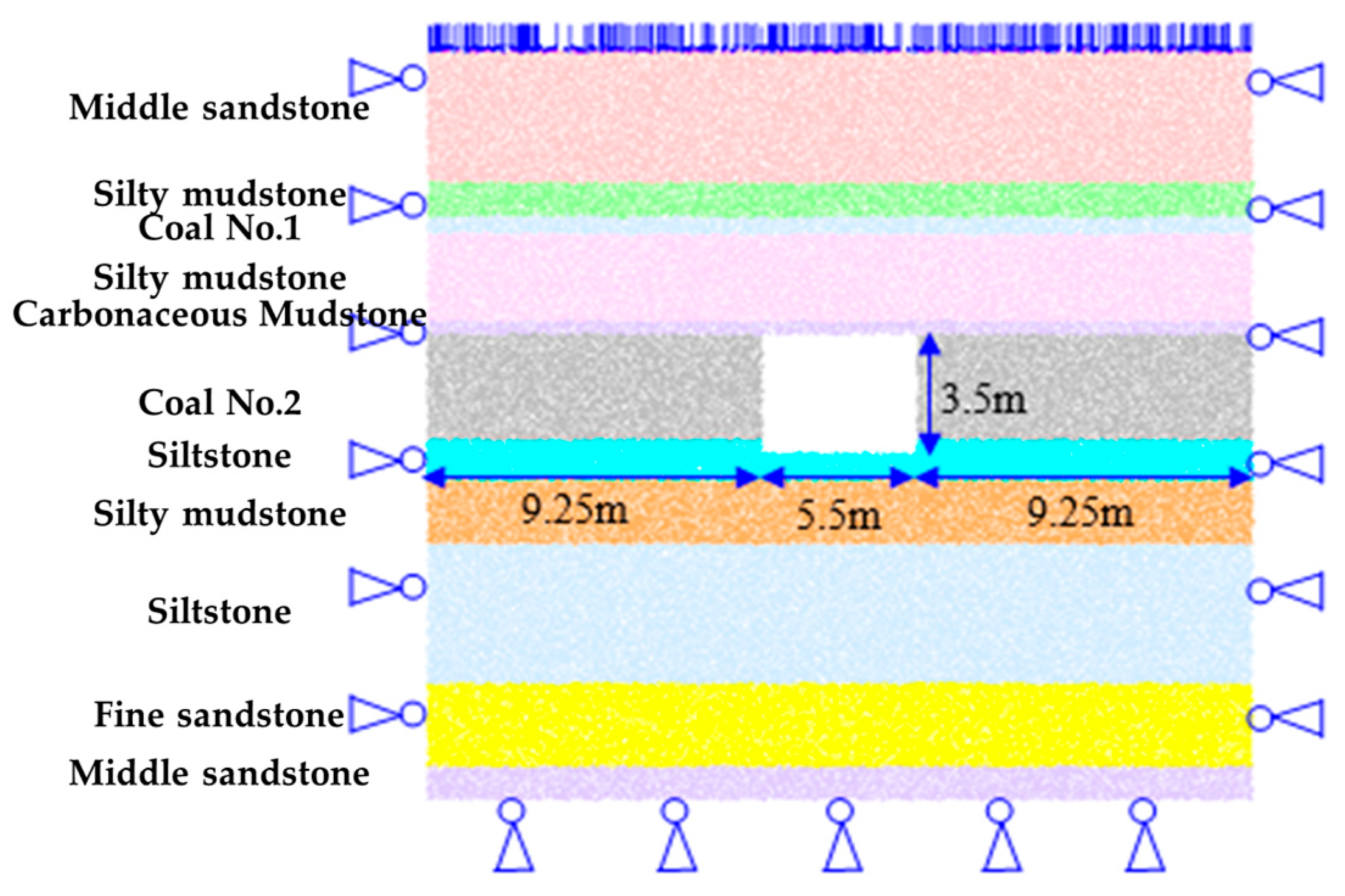
Based on the comprehensive stratigraphic column and the physical–mechanical parameters of the rock layers at Shuguang Coal Mine’s #1232 working face, along with the mining and excavation layout, a two-dimensional model (24 m long × 21.6 m high) was established to study the floor heave mechanism of the 1232 transportation roadway, as shown in Figure 4. The 1232 transportation roadway is centrally positioned within the model, with both sides located 9.75 m from the model boundaries. The model constrains horizontal displacement at the left and right boundaries, applies vertical displacement constraints at the base, and imposes a uniformly distributed load of 15 MPa on the top surface. The model is constructed using periodic block elements, with initial in situ stresses applied. The load-bearing layer is represented by converting the applied stress into force loads directly on the top particles of the model. Once the model reaches equilibrium under the applied in situ stresses, excavation of the 1232 transportation roadway is simulated.
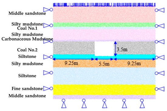
Figure 4.
Discrete element model of bottom drum in 1232 Transportation Lane of Shuguang Coal Mine.
The numerical model employs particles with a uniform radius distribution across all simulated strata, comprising a total of 53,418 particles to represent 11 distinct rock layers. To address the computational inefficiency associated with excessive particle generation using the compaction–rejection method, the model was constructed using periodic brick elements. Each brick element consists of a granular assembly within a periodic spatial domain, pre-equilibrated to ensure mechanical stability. This approach eliminates the need for additional computational time to achieve equilibrium during the model initialization phase, thereby streamlining the model establishment process. Upon assembling the periodic brick elements, initial in situ stresses were applied to the system. Specifically, the overburden load was converted into equivalent force vectors and directly applied to the top layer of particles. After achieving equilibrium under the initial in situ stresses, the excavation of the 1232 transportation roadway was simulated to investigate the dynamic response of the surrounding rock mass.
The Particle Flow Code (PFC) method, rooted in discontinuous medium mechanics theory, employs assemblies of discrete rigid particles to simulate the macroscopic mechanical behavior of materials. In this framework, particle overlaps are permitted to characterize contact forces governed by Newtonian dynamics, while the material’s macro-scale mechanical properties dynamically emerge from evolving interparticle contact states. The transition from pre-peak linear behavior to post-peak nonlinear characteristics is triggered by contact failures (e.g., shear or tensile failure modes), eliminating the need for predefined macroscopic constitutive relationships. Instead, micro-mechanical parameters—including particle gradation, stiffness coefficients, frictional properties, and bond strengths—indirectly govern the material’s macroscopic response. The term “particles” in PFC serves as an abstract representation of material behavior rather than literal granular constituents, enabling applications ranging from crystalline rock mechanics to amorphous material analysis. The collective mechanical complexity of particle assemblies (e.g., nonlinear deformation, failure patterns) manifests through contact mechanics: contact strength parameters dictate fundamental stress-bearing capacities (tension, compression, shear), while contact failure initiates internal crack propagation. Crucially, the stress-strain relationships under complex loading conditions are automatically derived through computational algorithms tracking microstructural evolution. This bottom-up modeling paradigm allows macroscopic material properties to naturally emerge from the progressive reconfiguration of microscopic contact networks, bypassing traditional phenomenological assumptions inherent in continuum-based approaches.
3.2. Analysis of Simulation Results
Analysis of Actual Floor Heave Deformation in the 1232 Transportation Roadway
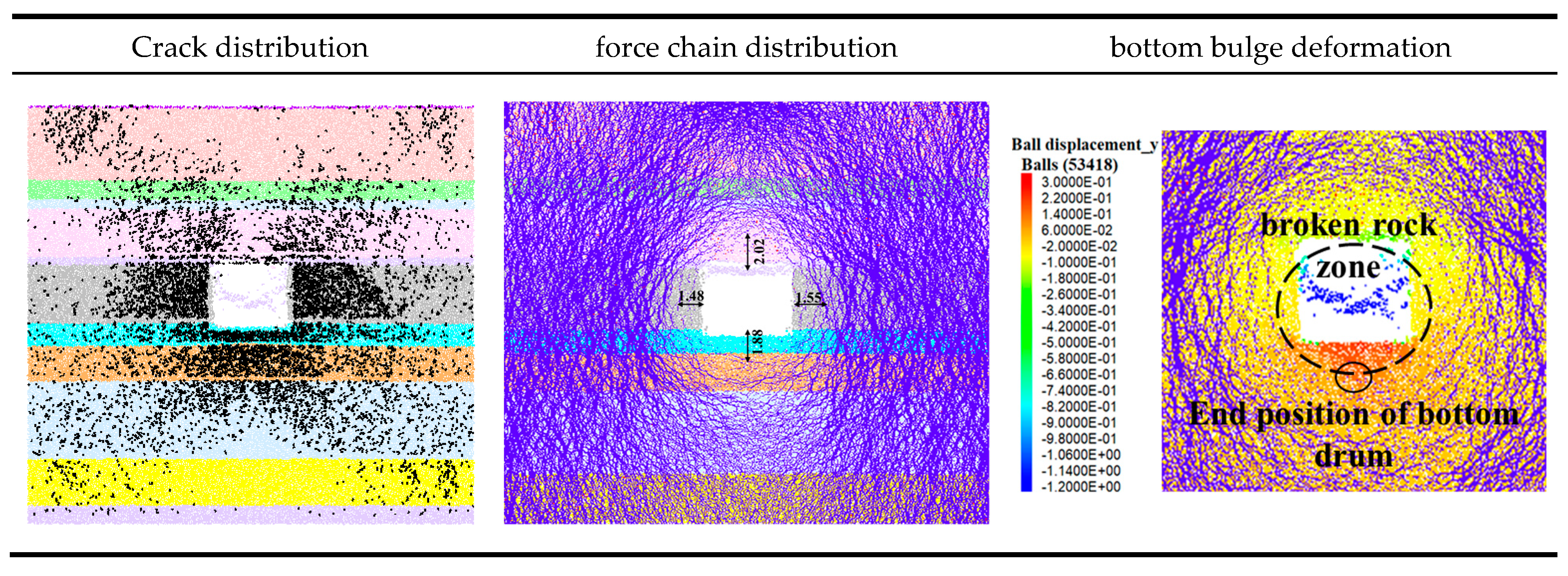
The characteristics of surrounding rock stress manifestation after excavation of the 1232 transportation roadway are shown in Figure 5. Following excavation, stress is released into the roadway, causing fractures to develop in the sidewalls, floor, and shoulder areas of the roof. These fractures exhibit a butterfly-shaped distribution. The force chain distribution indicates the formation of an elliptical stress-relief zone (loosening zone) in the surrounding rock, with an average extent of approximately 1.5 m in both sidewalls. The thick, silty mudstone in the floor is almost entirely fractured, with a failure depth reaching up to 2.5 m. Under the lateral load transfer from the sidewalls, the broken mudstone is compacted, forming a load-bearing structure. The above analysis shows that the extent of the loosening zone in the surrounding rock plays a controlling role in floor heave deformation. Its distribution in the floor determines both the termination position and the depth of the heave. As this study focuses on the influence of floor stratigraphy on floor heave, the effect of roadway support parameters was not considered in the model. If support parameters are taken into account, the extent of the loosening zone in the surrounding rock will be reduced, increasing the load transferred from the sidewalls to the floor, and consequently intensifying the floor heave deformation.
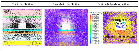
Figure 5.
Rock pressure characteristics of rock surrounding 1232 Yunxiang of Shuguang Coal Mine.
3.3. Analysis of Influencing Factors on Floor Heave
Roadway excavation and retreat mining operations lead to the redistribution of stress within the surrounding rock. When the floor loses displacement constraints, the combined effects of horizontal and vertical stresses cause internal failure in the floor strata, resulting in upward deformation and the formation of floor heave.
The butterfly-shaped fracture distribution arises from stress redistribution following roadway excavation. Vertical stress is released toward the free surface of the roadway, while horizontal stress is transferred laterally into the surrounding rock mass, resulting in compressive stress concentrations at the roof–floor corners and tensile stress zones along the sidewalls and floor. High deviatoric stress regions trigger diagonal shear fractures, whereas low-stress zones generate vertical tensile cracks. The interplay of these failure mechanisms forms the characteristic butterfly-shaped fracture pattern. Geometric symmetry of the roadway and lithological homogeneity promote stress redistribution through a self-stabilizing “stress arch”, redirecting stresses deeper into the strata while creating a symmetric loosening zone near the excavation. Progressive failure in composite strata further reinforces this pattern: weak layers (e.g., mudstone) experience rapid tensile fracturing due to low tensile strength, while stiff layers (e.g., sandstone) exhibit delayed shear failure. The spatiotemporal heterogeneity of failure across strata ultimately defines the distinct butterfly-shaped fracture geometry. This mechanism aligns with field observations in deep coal mines and classical theories of excavation-induced damage (e.g., Kang et al., 2015 [3]; He et al., 2009 [4]), validating its universality in geomechanical engineering.
During this process, the vertical stress acting on the floor surface significantly decreases, while the horizontal stress transferred from both sides gradually increases, shifting from compressive to tensile stress. As the stress redistributes, it transfers toward the goaf boundary, leading to instability and failure in the floor of the retreat roadway due to the increasing horizontal stresses transmitted from the sidewalls. Under high tensile stress, once the stress exceeds the rock’s ultimate tensile strength, progressive failure occurs, becoming a primary factor in the failure of floor strata in retreat roadways.
After roadway excavation during retreat mining, the loss of vertical constraint in the floor allows stress to be released toward the roadway, manifested as floor heave. From a mechanical perspective, floor heave is a progressive failure process that develops layer by layer from the shallow floor to deeper strata, until it reaches a competent bearing layer. This stable layer restricts further development of the heave. Therefore, floor heave in retreat roadways is governed by the layered failure characteristics of composite floor structures. According to composite plate theory, the flexural deformation of each floor rock layer is primarily influenced by three factors: stiffness, strength, and moment of inertia. The moment of inertia is largely affected by the thickness of the rock layers and the degree of joint development. By varying the stiffness, strength, and moment of inertia of the rock layers, the influence of each factor on floor heave can be systematically studied.
(1) Influence of Floor Stiffness and Strength on Floor Heave Deformation
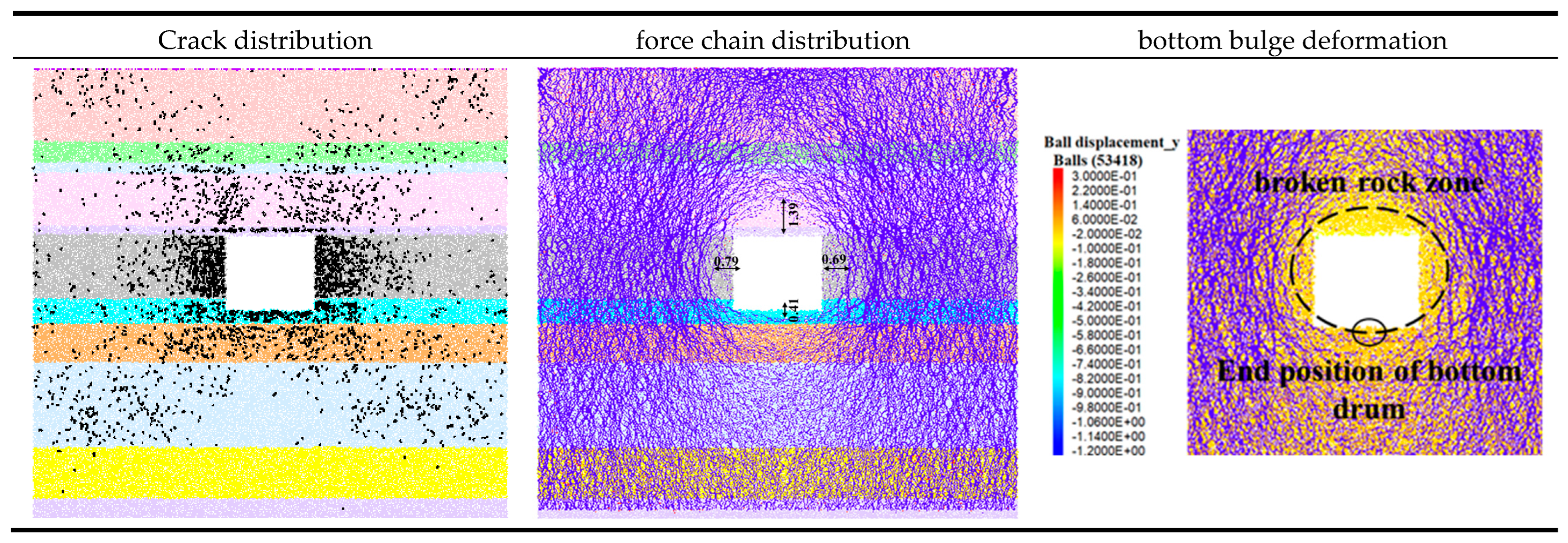
To investigate the influence of floor strength on floor heave deformation, the stiffness and strength of the first-layer siltstone, second-layer silty mudstone, and third-layer siltstone in the floor were increased by a factor of 2.5, while the parameters of the other strata in the model remained unchanged. The stress distribution characteristics after excavation with the strengthened floor are shown in Figure 6.
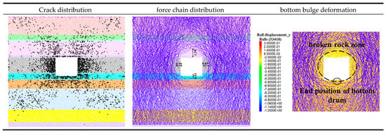
Figure 6.
Characteristics of rock pressure in the surrounding rock after strengthening the bottom plate of Shuguang Coal Mine.
After excavation with the strengthened floor, fewer fractures developed, primarily concentrated in the sidewalls. Fracture development in both the floor and roof significantly decreased, with most of the floor cracks confined to shallow depths. The force chain distribution indicates that the stress-bearing arch in the surrounding rock shifted closer to the roadway, and the extent of the loosening zone was significantly reduced. The loosening zone in the sidewalls decreased from 1.5 m to 0.7 m, the stress-reduced zone in the roof narrowed from 2.02 m to 1.39 m, and the failure depth in the floor was reduced from 2.5 m to 0.41 m. Ultimately, the floor heave was limited to no more than 4 cm.
Increasing the stiffness and strength of the floor generally enhances its stability. A stable floor can withstand greater stress and more effectively distribute loads, thereby reducing flexural deformation and minimizing floor heave. After floor reinforcement in the 1232 roadway, deformation and failure of the roof and sidewalls were restrained, the load-bearing capacity of the sidewalls was improved, the loosening zone was reduced, and floor heave deformation was effectively mitigated.
(2) Influence of Floor Layer Thickness and Joint Development on Floor Heave Deformation
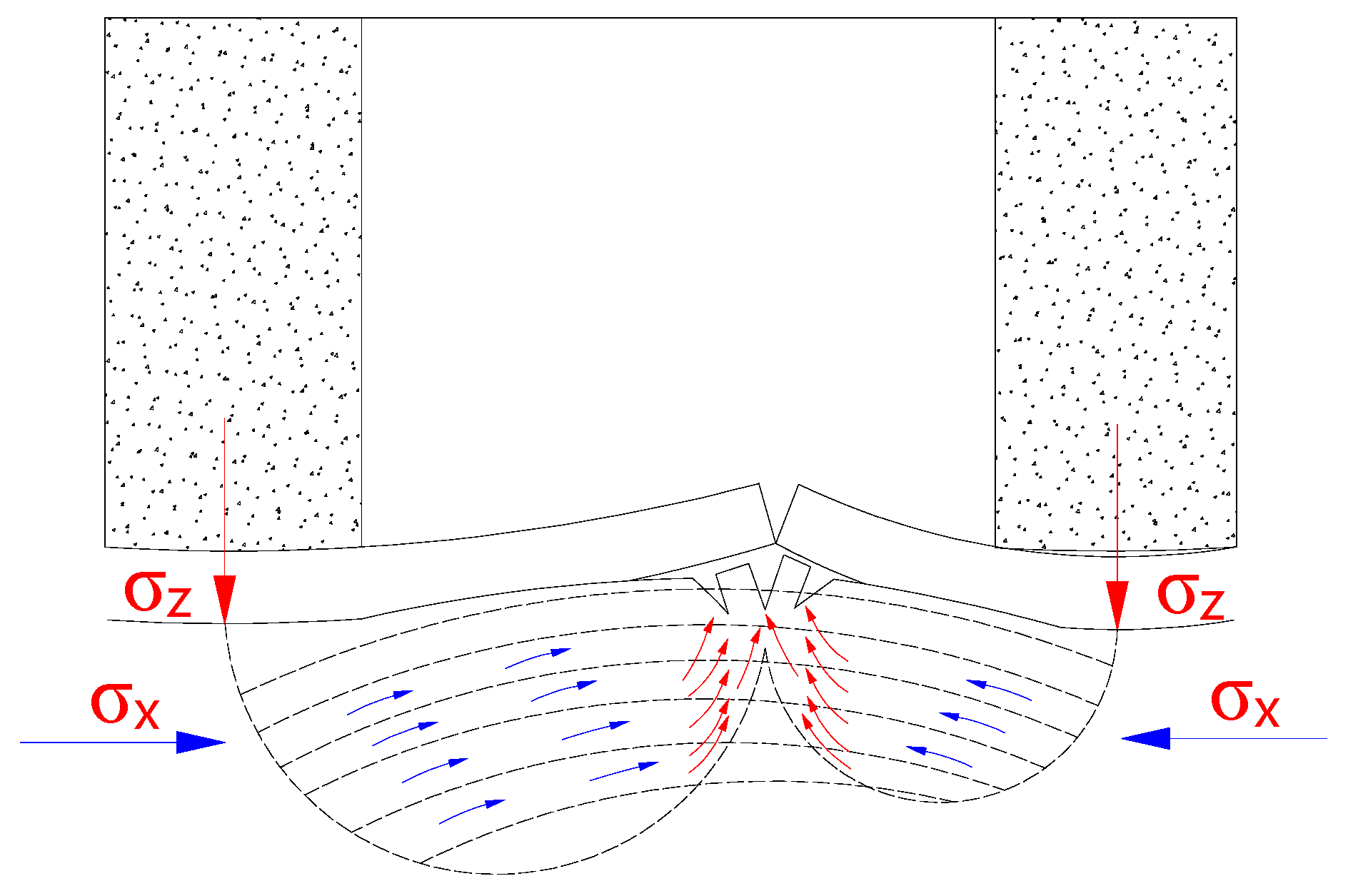
The floor strata can be regarded as a composite beam structure. Under vertical stress disturbances from the roof and coal pillar, the beam ends are subjected to loads exceeding their bearing capacity, while simultaneously experiencing horizontal compressive forces due to stratum movement. This results in flexural deformation and upward arching of the beam, eventually leading to failure through a layer-by-layer failure process, as illustrated in Figure 7. The location and extent of joint development within the floor strata affect the composite beam’s resistance to deformation. Consequently, the degree of jointing directly influences the extent of floor heave.
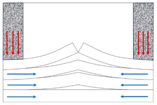
Figure 7.
The composite beam of the bottom plate gradually bends and bulges, layer by layer.
1) Single Joint Located in the Middle of the Second Floor Stratum
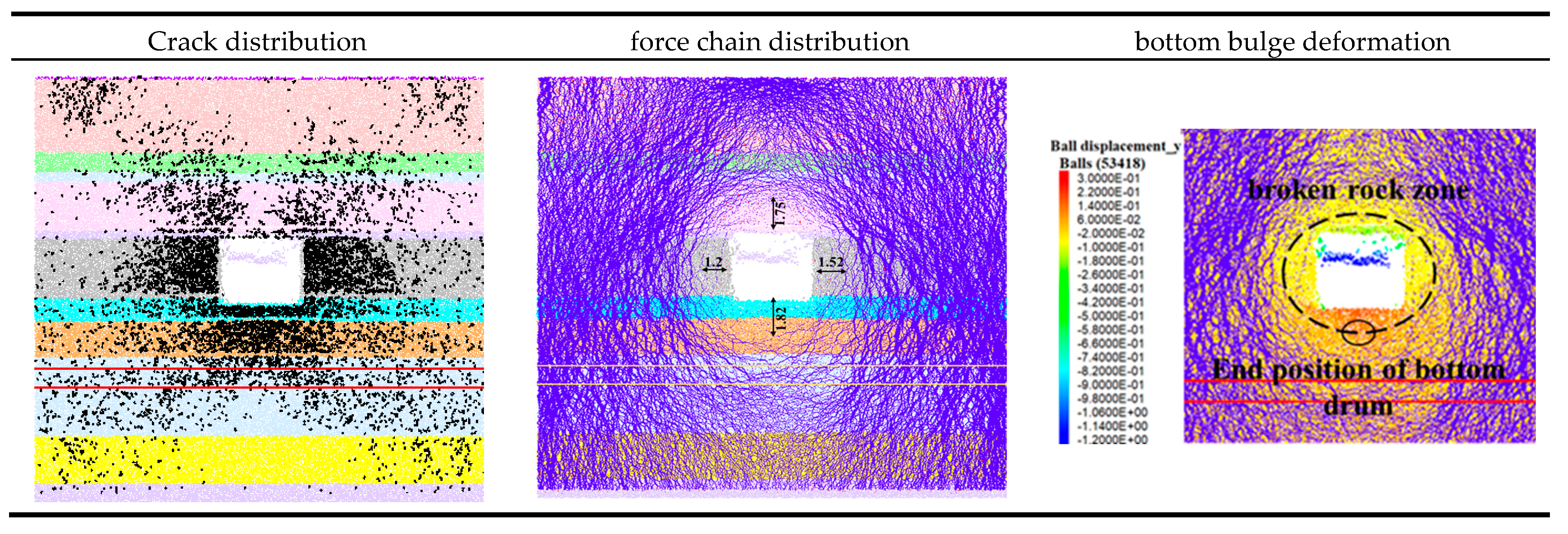
When a single joint is located in the middle of the second floor stratum, the stress characteristics of the surrounding rock after excavation of the 1232 transportation roadway are shown in Figure 8. Following excavation, stress is released into the roadway, leading to fracture development in the sidewalls, floor, and shoulder areas of the roof, exhibiting a butterfly-shaped distribution. According to the force chain distribution, the loosening zone in the surrounding rock of the roadway is elliptical in shape, with an average extent of approximately 1.5 m on both sides. The thick, silty mudstone in the floor is almost completely fractured, with a failure depth of up to 2.5 m. The fractured mudstone is compacted under lateral load transfer from the sidewalls, forming a load-bearing structure. The floor heave exceeds 30 cm and terminates at the upper boundary of the load-bearing structure formed by the broken silty mudstone. This boundary also corresponds to the edge of the loosening zone in the 1232 roadway’s surrounding rock.
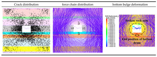
Figure 8.
A single joint is located in the middle of the second layer of rock strata on the floor, and the rock pressure characteristics of the rock surrounding the 1232 transportation roadway.
The second layer of the floor stratum is completely damaged under the combined effects of stress release due to excavation and lateral load transfer from the sidewalls. The presence of a single joint in the middle of this layer does not significantly alter the composite beam’s resistance to floor heave deformation. Therefore, when a single joint is located in the middle of the second floor layer, the stress characteristics of the surrounding rock in the 1232 roadway do not exhibit significant changes.
2) Single Joint Located 1 m Below the Top of the Third Floor Stratum
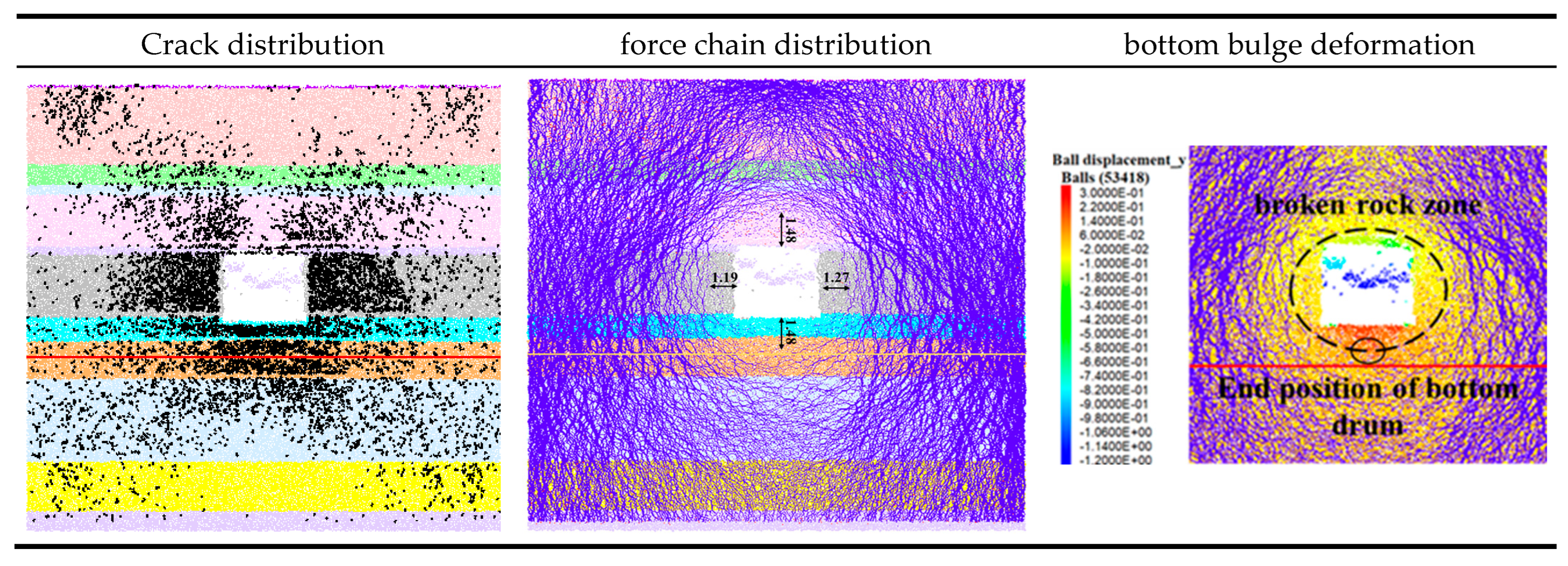
When a single joint is located 1 m below the top of the third floor stratum, the stress characteristics of the surrounding rock after excavation of the 1232 transportation roadway are shown in Figure 9. the original 4.18-m-thick siltstone layer is divided into two layers with thicknesses of 1 m and 3.18 m. This segmentation reduces the overall resistance of the composite floor beam to floor heave deformation, leading to increased fracture development, expansion of the loosening zone, and intensified floor heave. According to the simulation results, when the joint is located 1 m below the top of the third floor stratum, the surrounding rock of the 1232 roadway exhibits the following stress characteristics: fractures develop in the sidewalls, floor, and roof shoulders, forming a butterfly-shaped pattern; the number of fractures increases compared to previous cases. The loosening zone in the surrounding rock remains elliptical, with an average width of 1.6 m on both sides. Floor failure extends to the stratification layer at a depth of 3.5 m.
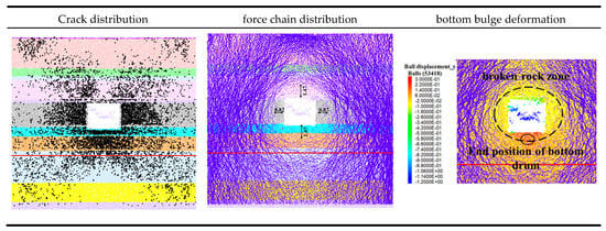
Figure 9.
The rock pressure characteristics of the rock surrounding the 1232 transportation roadway, where a single joint is located 1 m below the top of the third rock layer on the bottom plate.
(3) Two Joints Located 1 m and 2 m Below the Top of the Third Floor Stratum
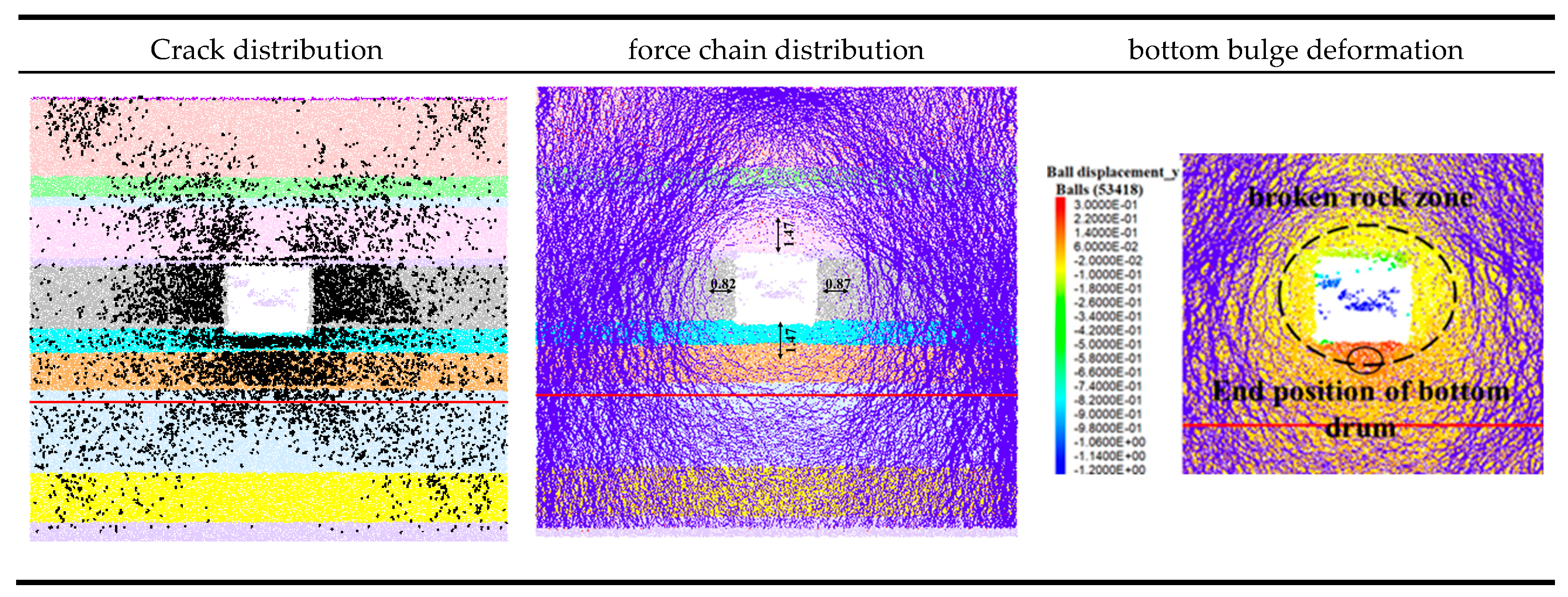
When two joints are located 1 m and 2 m below the top of the third floor stratum, the stress characteristics of the surrounding rock after excavation of the 1232 transportation roadway are shown in Figure 10. the original 4.18-m-thick siltstone is divided into three layers of 1 m, 1 m, and 2.18 m in thickness. This further reduces the composite floor beam’s resistance to floor heave deformation, and theoretically leads to more extensive fracturing, larger loosening zones, and increased floor heave. However, simulation results show that the stress characteristics of the 1232 roadway’s surrounding rock under the condition of two joints at 1 m and 2 m depth are consistent with those under a single joint at 1 m depth, showing no significant changes. The force chain distribution reveals that the horizontal compression between the two joints located at 1 m and 2 m depth forms a hinged structure. This increases the floor’s bearing stress and effectively limits the downward propagation of floor heave, resulting in a maximum heave depth.
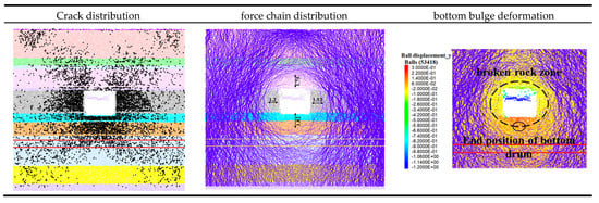
Figure 10.
Double joints are located at 1 m and 2 m below the top of the third rock layer on the bottom plate. Characteristics of rock pressure in the rock surrounding the 1232 transportation roadway.
As a result, the extent of floor heave shows little difference compared to the case with a single joint at 1 m depth. The fractured rock mass between the two joints forms a compacted structure that constrains further heave, defining the maximum depth range of floor heave, as illustrated in Figure 11.

Figure 11.
The compression structure of the fractured rock layer on the bottom plate restricts the deformation of the floor bulge.
As the joints extend deeper into the floor strata, when a joint is located in a layer close to the immediate floor, its influence on floor heave is minimal, since the first floor layer is already completely damaged. However, when the joint is located in deeper strata farther from the immediate floor, and the fractured rock fails to form a compacted, stable load-bearing structure, the extent of floor heave increases. If the fractured rock mass forms a load-bearing structure, it can reduce floor bending and deformation, effectively preventing further downward propagation of the heave. As a result, the maximum depth of floor heave is limited to the upper boundary of the bearing structure formed after rock failure.
4. Research on Slotting and Pressure Relief Control Technology
4.1. Floor Heave Control Scheme
Slotting and pressure relief in the floor can effectively alleviate stress concentration, improve the mechanical state of the surrounding rock, reduce support costs and maintenance frequency, and adapt flexibly to complex geological conditions. In the 1232 retreat roadway of Shuguang Coal Mine, the floor is primarily composed of mudstone, which has relatively low strength. Therefore, it is proposed that slotting and pressure relief be implemented under the original support conditions in the 1232 transportation roadway of Shuguang Coal Mine. To this end, a technologically advanced, safe, and efficient floor-slotting machine was designed and developed for field industrial trials, aiming to effectively mitigate floor heave and achieve engineering control objectives in the roadway.
4.2. Key Parameters for Slotting Control of Floor Heave in the 1232 Transportation Roadway of Shuguang Mine
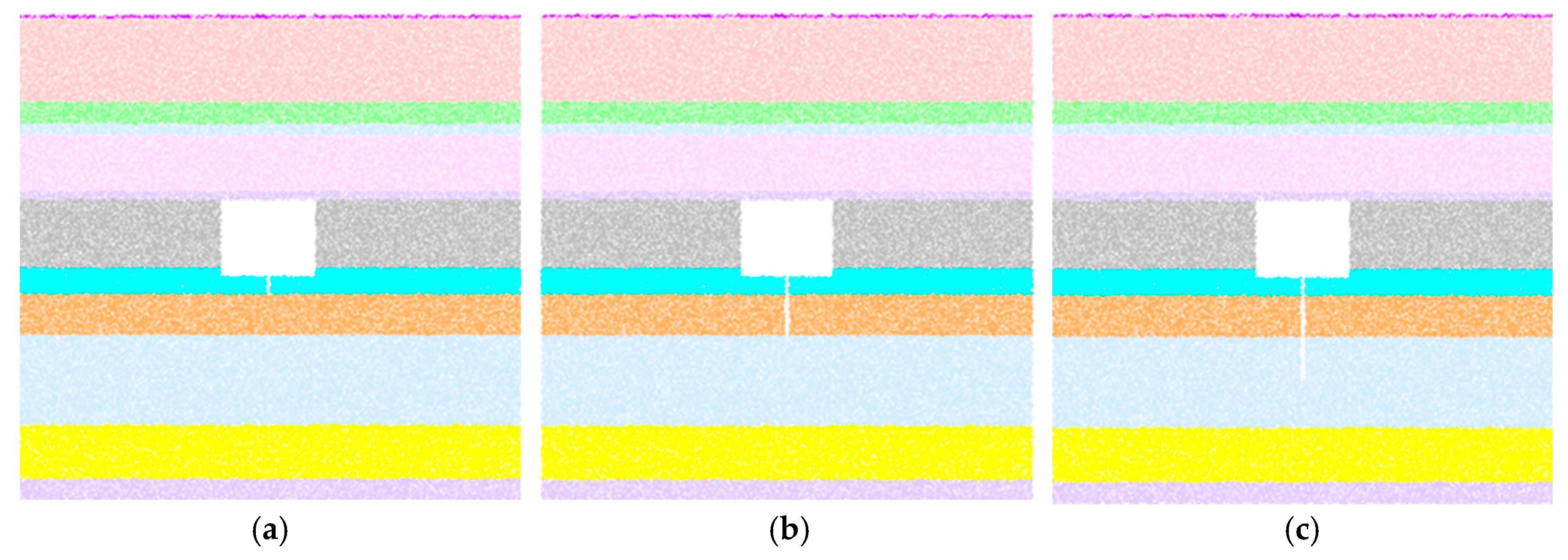
To understand the control mechanism of slotting depth on floor heave deformation, three numerical models were developed: one where the slot penetrates the first floor layer, one that penetrates the second, and one that reaches the third. In all models, the slot width was set to 20 cm, as shown in Figure 12. The slotting width should be determined based on roadway production and technical constraints, and generally should not exceed 30 cm.
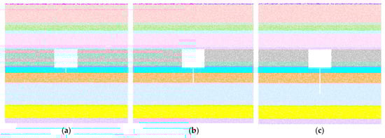
Figure 12.
Numerical model for determining the depth of groove cutting in the bottom drum controlled by groove cutting control. (a) Slotting through the first floor stratum; (b) Slotting through the second floor stratum; (c) Slotting to 2 m below the top of the third floor stratum.
(1) Shallow Slotting (Penetrating the First Floor Layer)
When the slot penetrates the first floor layer, the stress characteristics of the surrounding rock after excavation of the 1232 transportation roadway are shown in Figure 13. Compared to the condition before slotting, stress release causes a similar number and pattern of fractures, with butterfly-shaped distributions primarily concentrated in the sidewalls and floor. The force chain distribution indicates that both cases share similar loosening zone characteristics: the sidewall loosening zone extends about 1.5 m, and the floor loosening zone reaches a depth of 2.5 m. Slotting does not alter the depth or degree of floor failure; the second layer of thick silty mudstone in the floor is completely damaged both before and after slotting. Prior to slotting, the maximum floor heave deformation exceeds 30 cm. After slotting, the created slotting space allows for the movement of fractured floor material, thereby reducing the maximum floor heave deformation to approximately 10 cm.
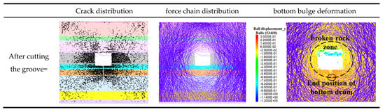
Figure 13.
Cut through the first layer of rock layer 1232 of the bottom plate by slotting and the characteristics of rock pressure in the rock surrounding the transportation roadway.
When the slot penetrates the first floor stratum, it lies entirely within the shallow fractured zone. While it contains the floor heave deformation of the shallow layers within the slotting space, it does not alter the movement characteristics of deeper fractured strata. Therefore, its overall effect on controlling floor heave deformation is limited.
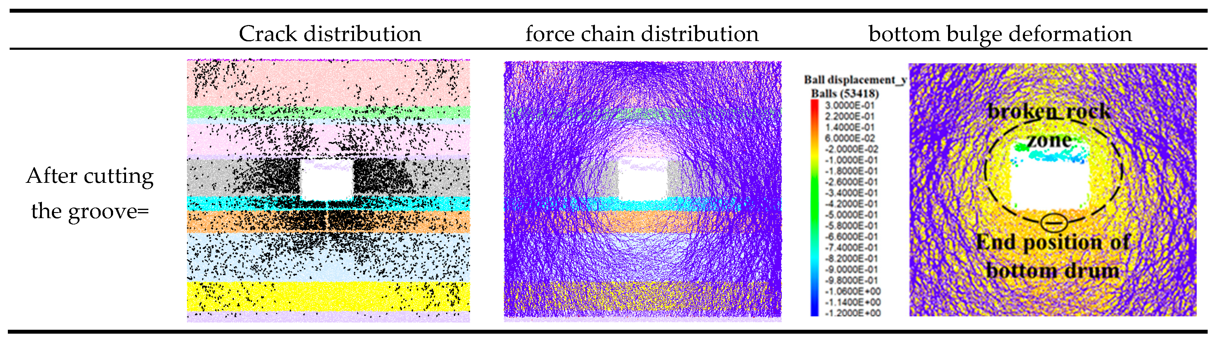
(2) Intermediate Slotting (Penetrating the Second Floor Stratum)
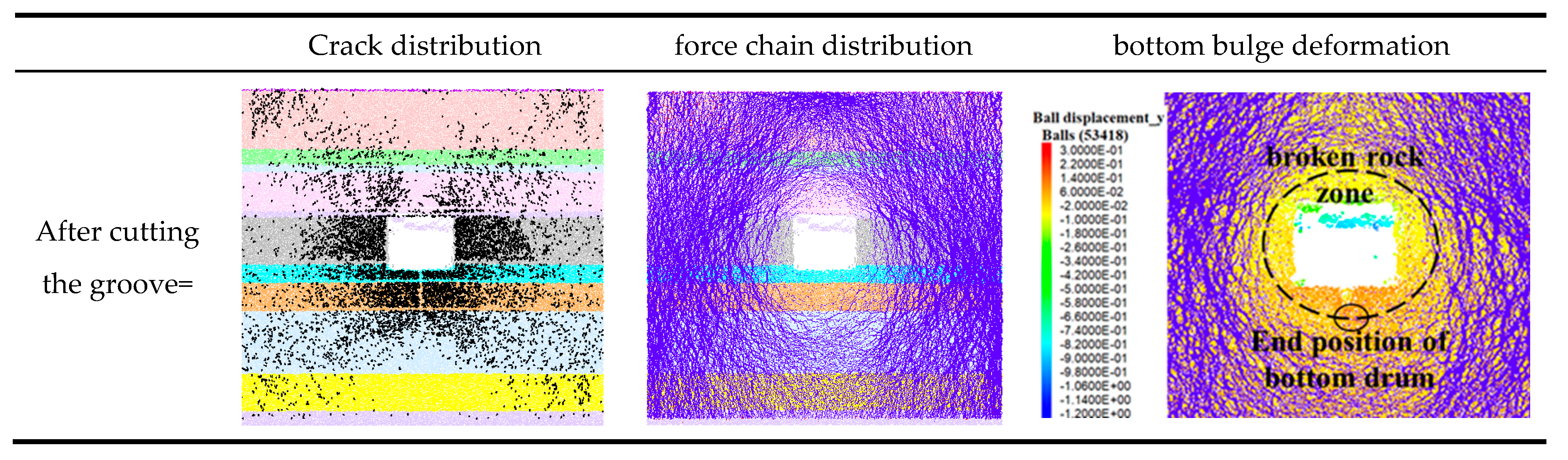
When the slot penetrates the second floor stratum, the stress characteristics of the surrounding rock after excavation of the 1232 transportation roadway are shown in Figure 14. Compared to the pre-slotting condition, the fracture distribution still exhibits a butterfly-shaped pattern, mainly concentrated in the sidewalls and floor, with an increased number of fractures in the floor. The loosening zones in the sidewalls and roof of the 1232 roadway remain largely unchanged, while the loosened zone in the floor expands. As the slot cuts through the second floor stratum, this layer bears little to no load. The unloading range of the floor increases, and the primary load-bearing structure shifts from the second to the third floor stratum. The maximum floor heave deformation is reduced to approximately 10 cm.
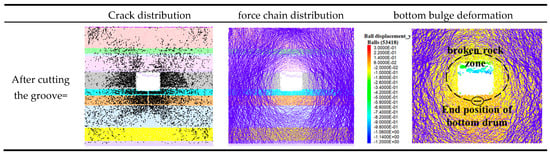
Figure 14.
Cut through the bottom plate of the second layer of rock layer 1232 and the characteristics of rock pressure in the rock surrounding the transportation roadway.
The identical floor heave reduction observed under both shallow and intermediate slotting conditions arises because these methods partially relieve stresses and modify the load-bearing structure. However, due to inherent limitations in stratum strength and load-bearing structure distribution, they fail to fully eliminate deformation. In contrast, deep slotting achieves superior control by inducing more comprehensive stress redistribution and a downward shift of the load-bearing structure. This deeper intervention transfers loads to stable, less disturbed strata, thereby minimizing residual deformation through enhanced mechanical stability.
After the third floor stratum in the 1232 transportation roadway fails, a compacted load-bearing structure is formed, which effectively limits the further downward development of floor heave deformation. When the slot penetrates the second floor stratum, it provides sufficient space for floor deformation, thereby effectively controlling floor heave.
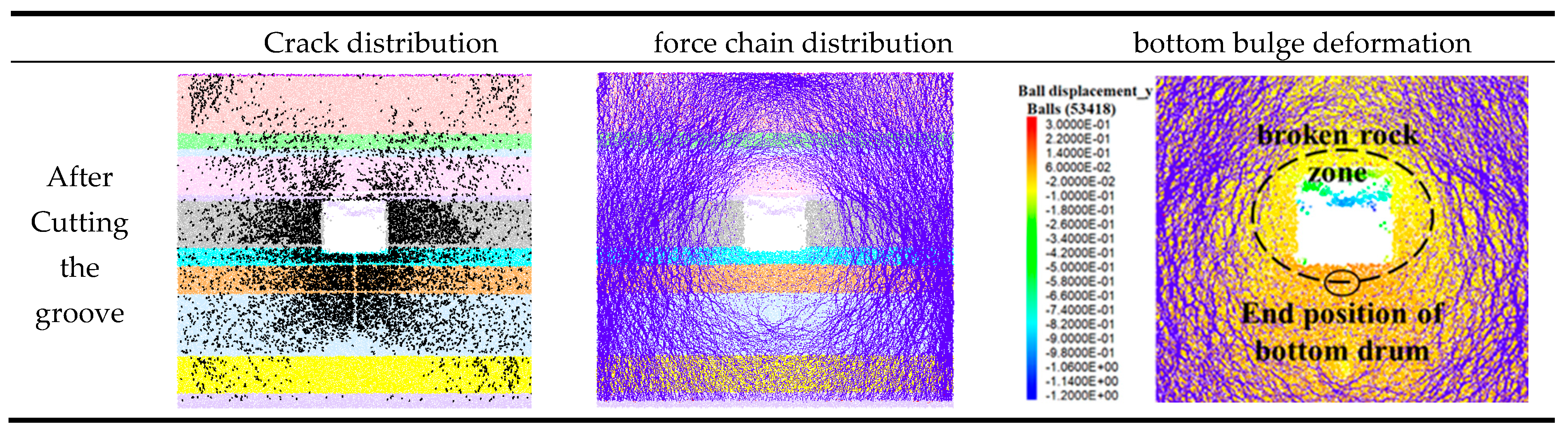
(3) Deep Slotting (2 m Below the Top of the Third Floor Stratum)
When the slot penetrates to 2 m below the top of the third floor stratum, the stress characteristics of the surrounding rock after excavation of the 1232 roadway are shown in Figure 15. Compared to the pre-slotting condition, the fractures still exhibit a butterfly-shaped distribution, primarily concentrated in the sidewalls and floor, with a noticeable increase in the number of floor fractures. The loosening zones in both sidewalls and the floor are significantly enlarged. Due to the deeper slotting, the floor unloading zone expands, enlarging the stress-reduction area in the sidewalls and shifting the primary floor bearing structure further downward. As a result, the maximum floor heave deformation is reduced to approximately 6 cm.
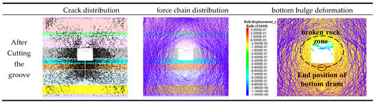
Figure 15.
Cut through the top 2 m of the third layer of rock strata on the bottom plate, and analysis of the rock pressure characteristics of the surrounding rock in the 1232 roadway.
Greater slotting depths can alter the stress arch distribution in the sidewalls and floor, shifting the arches into deeper surrounding rock, which is beneficial for controlling floor heave. However, considering mining technical conditions, slotting efficiency, and equipment capabilities, excessively deep slots are not advisable. A reasonable depth should reach just above the main load-bearing structure in the floor to balance effectiveness and feasibility.
5. Summary and Conclusions
(1) The floor strata can be conceptualized as a composite beam structure. When subjected to vertical stress disturbances from the roof and coal pillars, the beam ends experience loads exceeding their bearing capacity, coupled with horizontal compressive forces induced by stratum movement. This results in flexural deformation and upward arching of the beam until failure, manifesting as layer-by-layer progressive failure. Floor heave in retreat roadways is governed by the stratified failure characteristics of composite floor strata. According to composite plate theory, the flexural deformation of individual floor layers depends primarily on three factors: stiffness, strength, and moment of inertia. The moment of inertia is predominantly influenced by stratum thickness and joint development.
(2) Enhanced strength and stiffness of floor strata constrain the failure and displacement of the sidewalls and roof, thereby improving the load-bearing capacity of the sidewalls, reducing the extent of the surrounding rock loosening zone, and mitigating floor heave deformation. The joint distribution within the floor strata critically affects the composite rock mass’s resistance to heave. Shallow joints exhibit negligible impact due to the complete failure of shallow strata under stress redistribution. However, as joints extend into deeper strata, the composite system’s resistance to heave diminishes, leading to amplified deformation. When joints penetrate beyond a critical depth, fractured strata form a compacted load-bearing structure that confines heave propagation, with maximum heave depth localized above this stabilizing structure.
(3) Shallow slotting within the fractured zone confines heave deformation to the slotting space but fails to alter the migration characteristics of deeper fractured strata, resulting in limited control efficacy. In contrast, deeper slotting modifies the stress arch distribution in the sidewalls and floor, redirecting stresses into deeper rock masses and significantly improving heave suppression. Considering practical constraints—such as mining technical conditions, slotting efficiency, and equipment capabilities—excessively deep slotting is not advisable. The optimal slotting depth should terminate immediately above the primary load-bearing structure, balancing control effectiveness and engineering feasibility.
(4) The PFC model with smooth joints successfully reproduced the full floor heave process—“deformation–separation–fracture–compaction”—overcoming the limitations of traditional continuum methods in simulating discontinuous failure. Comparative analyses of crack propagation and force chain evolution under varying joint distributions and slotting parameters confirm the advantages of discrete element methods in revealing rock mass micro-failure mechanisms, providing methodological insights for similar engineering studies.
Author Contributions
Conceptualization, T.L.; Formal analysis, T.L and B.H.; Software, T.L. and C.S. All authors have read and agreed to the published version of the manuscript.
Funding
This research received no external funding.
Data Availability Statement
The data presented in this study are available on request from the corresponding author.
Conflicts of Interest
The authors declare no conflicts of interest.
References
- Xiong, Y.; Kong, D.Z.; Yang, S.L.; Wu, G.; Zuo, Y.; Cheng, Z. Comprehensive identification of coal wall stability in steeply inclined working faces using cloud model. China Saf. Sci. J. 2022, 32, 144–151. [Google Scholar]
- Kang, H.P. Mechanism and Prevention of Floor Heave in Soft Rock Roadways; China Coal Industry Publishing House: Beijing, China, 1993. [Google Scholar]
- Kang, H.P.; Fan, M.J.; Gao, F.Q.; Zhang, H. Deformation characteristics and support technology of roadways in ultra-deep coal mines over 1000 meters. Chin. J. Rock Mech. Eng. 2015, 34, 2227–2241. [Google Scholar]
- He, M.C.; Zhang, G.F.; Wang, G.L.; Xu, Y.L.; Wu, C.Z.; Tang, Q.D. Control mechanism and application of floor heave in deep coal roadways. Chin. J. Rock Mech. Eng. 2009, 28, 2593–2598. [Google Scholar]
- He, M.C.; Zou, Z.S.; Zou, Y.F. Introduction to Soft Rock Roadway Engineering; China University of Mining and Technology Press: Xuzhou, China, 1993. [Google Scholar]
- He, M.C. Theory and Practice of Soft Rock Roadway Support in Chinese Coal Mines; China University of Mining and Technology Press: Xuzhou, China, 1996. [Google Scholar]
- Li, S.Y. Study on the Mechanism and Control of Floor Heave in Soft Rock Withdrawal Roadway; Taiyuan University of Technology: Taiyuan, China, 2020. [Google Scholar]
- Indraratna, B.; Nemcik, J.A.; Gale, W.J. Review and interpretation of primary floor failure mechanism at a longwall coal mining face based on numerical analysis. Geotechnique 2000, 50, 547–557. [Google Scholar] [CrossRef]
- Xu, X.D. Mechanism of Strong Ground Pressure Manifestation and Pressure Relief Control in Gob-Side Roadways of Extra-Thick Coal Seams in Caojiatan Mine; Jilin University: Changchun, China, 2022. [Google Scholar]
- Song, H.H.; Zhao, Y.X.; Jiang, Y.D.; Zhang, X.Z. Influence of coal heterogeneity on failure characteristics under uniaxial compression. J. China Coal Soc. 2017, 42, 3125–3132. [Google Scholar]
- Wang, X.Q.; Kan, J.G.; Jiao, J.K. Mechanism and control practice of floor heave in high-stress soft rock roadways. J. Min. Saf. Eng. 2017, 34, 214–220+227. [Google Scholar]
- Zhu, X.X. Study on Control Mechanism of Floor Heave in Dynamic Pressure Roadways of Yuwu Coal Mine; China University of Mining and Technology: Xuzhou, China, 2019. [Google Scholar]
- Li, Y.J. Analysis of floor heave mechanism and control technology in mining-affected roadways. Coal Chem. Ind. 2017, 40, 31–33. [Google Scholar]
- Guo, B.H.; Lu, T.K. Mechanism of floor heave in deep roadways and slotting control technology. J. Min. Saf. Eng. 2008, 1, 91–94. [Google Scholar]
- Hou, C.J. Key technologies for controlling surrounding rock in deep roadways. J. China Univ. Min. Technol. 2017, 46, 970–978. [Google Scholar]
- Mo, S.; Tutuk, K.; Saydam, S. Management of floor heave at Bulga Underground Ope rations—A case study. Int. J. Min. Sci. Technol. 2019, 29, 73–78. [Google Scholar] [CrossRef]
- Ren, Z.; Zhang, C.; Wang, Y.; Yang, S.; Li, Q. Collaborative movement characteristics of overlying rock and loose layer based on block–particle discrete-element simulation method. Int. J. Coal Sci. Technol. 2025, 12, 17. [Google Scholar] [CrossRef]
- Han, P.; Wang, K.; Pang, J.; Ji, X.; Zhang, C. Response properties of geometries of coal penetrating fracture on seepage behavior. Int. J. Min. Sci. Technol. 2025, 35, 191–211. [Google Scholar] [CrossRef]
- Zhang, C.; Chen, Y.; Wang, Y.; Bai, Q. Discrete element method simulation of granular materials considering particle breakage in geotechnical and mining engineering: A short review. Green Smart Min. Eng. 2024, 1, 190–207. [Google Scholar] [CrossRef]
- Han, L.; Hou, S.Y.; Zhang, X.K. Mechanism and control technology of floor heave in steeply inclined coal seam roadways. Saf. Coal Mines 2018, 49, 209–212+217. [Google Scholar]
- Wei, J.Q.; Xu, Y.; Xu, Z.Q.; Li, D.X.; Cui, J.Q.; Wang, X.L. Energy transfer law and control during floor heave in roadways. Met. Mine 2021, 2, 29–35. [Google Scholar]
- Li, L.; Duan, X.B. Study on slotting control technology for floor heave in Yitang coal mine roadways. Shanxi Coal 2020, 40, 1–4. [Google Scholar]
- Zhou, R. Pressure relief support technology for return air roadways in deep mine with soft surrounding rock. Shandong Coal Sci. Technol. 2020, 4, 79–82. [Google Scholar]
- Yang, R.; Hao, B.Y. Pressure Relief Control Technology for Floor Heave in Mining Roadways; Taiyuan University of Technology: Taiyuan, China, 2022. [Google Scholar]

Disclaimer/Publisher’s Note: The statements, opinions and data contained in all publications are solely those of the individual author(s) and contributor(s) and not of MDPI and/or the editor(s). MDPI and/or the editor(s) disclaim responsibility for any injury to people or property resulting from any ideas, methods, instructions or products referred to in the content. |
© 2025 by the authors. Licensee MDPI, Basel, Switzerland. This article is an open access article distributed under the terms and conditions of the Creative Commons Attribution (CC BY) license (https://creativecommons.org/licenses/by/4.0/).