3.1. Model Construction
Due to its depth (≈600 m) and structural background, vertical stress dominates in Shuguang Coal Mine. On site monitoring shows that vertical stress accounts for about 85% of the total stress concentration in the bottom strata. Therefore, this study considered vertical stress and applied horizontal displacement constraints to establish a model.
Based on the comprehensive stratigraphic column and the physical–mechanical parameters of the rock layers at Shuguang Coal Mine’s #1232 working face, along with the mining and excavation layout, a two-dimensional model (24 m long × 21.6 m high) was established to study the floor heave mechanism of the 1232 transportation roadway, as shown in
Figure 4. The 1232 transportation roadway is centrally positioned within the model, with both sides located 9.75 m from the model boundaries. The model constrains horizontal displacement at the left and right boundaries, applies vertical displacement constraints at the base, and imposes a uniformly distributed load of 15 MPa on the top surface. The model is constructed using periodic block elements, with initial in situ stresses applied. The load-bearing layer is represented by converting the applied stress into force loads directly on the top particles of the model. Once the model reaches equilibrium under the applied in situ stresses, excavation of the 1232 transportation roadway is simulated.
The numerical model employs particles with a uniform radius distribution across all simulated strata, comprising a total of 53,418 particles to represent 11 distinct rock layers. To address the computational inefficiency associated with excessive particle generation using the compaction–rejection method, the model was constructed using periodic brick elements. Each brick element consists of a granular assembly within a periodic spatial domain, pre-equilibrated to ensure mechanical stability. This approach eliminates the need for additional computational time to achieve equilibrium during the model initialization phase, thereby streamlining the model establishment process. Upon assembling the periodic brick elements, initial in situ stresses were applied to the system. Specifically, the overburden load was converted into equivalent force vectors and directly applied to the top layer of particles. After achieving equilibrium under the initial in situ stresses, the excavation of the 1232 transportation roadway was simulated to investigate the dynamic response of the surrounding rock mass.
The Particle Flow Code (PFC) method, rooted in discontinuous medium mechanics theory, employs assemblies of discrete rigid particles to simulate the macroscopic mechanical behavior of materials. In this framework, particle overlaps are permitted to characterize contact forces governed by Newtonian dynamics, while the material’s macro-scale mechanical properties dynamically emerge from evolving interparticle contact states. The transition from pre-peak linear behavior to post-peak nonlinear characteristics is triggered by contact failures (e.g., shear or tensile failure modes), eliminating the need for predefined macroscopic constitutive relationships. Instead, micro-mechanical parameters—including particle gradation, stiffness coefficients, frictional properties, and bond strengths—indirectly govern the material’s macroscopic response. The term “particles” in PFC serves as an abstract representation of material behavior rather than literal granular constituents, enabling applications ranging from crystalline rock mechanics to amorphous material analysis. The collective mechanical complexity of particle assemblies (e.g., nonlinear deformation, failure patterns) manifests through contact mechanics: contact strength parameters dictate fundamental stress-bearing capacities (tension, compression, shear), while contact failure initiates internal crack propagation. Crucially, the stress-strain relationships under complex loading conditions are automatically derived through computational algorithms tracking microstructural evolution. This bottom-up modeling paradigm allows macroscopic material properties to naturally emerge from the progressive reconfiguration of microscopic contact networks, bypassing traditional phenomenological assumptions inherent in continuum-based approaches.
3.3. Analysis of Influencing Factors on Floor Heave
Roadway excavation and retreat mining operations lead to the redistribution of stress within the surrounding rock. When the floor loses displacement constraints, the combined effects of horizontal and vertical stresses cause internal failure in the floor strata, resulting in upward deformation and the formation of floor heave.
The butterfly-shaped fracture distribution arises from stress redistribution following roadway excavation. Vertical stress is released toward the free surface of the roadway, while horizontal stress is transferred laterally into the surrounding rock mass, resulting in compressive stress concentrations at the roof–floor corners and tensile stress zones along the sidewalls and floor. High deviatoric stress regions trigger diagonal shear fractures, whereas low-stress zones generate vertical tensile cracks. The interplay of these failure mechanisms forms the characteristic butterfly-shaped fracture pattern. Geometric symmetry of the roadway and lithological homogeneity promote stress redistribution through a self-stabilizing “stress arch”, redirecting stresses deeper into the strata while creating a symmetric loosening zone near the excavation. Progressive failure in composite strata further reinforces this pattern: weak layers (e.g., mudstone) experience rapid tensile fracturing due to low tensile strength, while stiff layers (e.g., sandstone) exhibit delayed shear failure. The spatiotemporal heterogeneity of failure across strata ultimately defines the distinct butterfly-shaped fracture geometry. This mechanism aligns with field observations in deep coal mines and classical theories of excavation-induced damage (e.g., Kang et al., 2015 [
3]; He et al., 2009 [
4]), validating its universality in geomechanical engineering.
During this process, the vertical stress acting on the floor surface significantly decreases, while the horizontal stress transferred from both sides gradually increases, shifting from compressive to tensile stress. As the stress redistributes, it transfers toward the goaf boundary, leading to instability and failure in the floor of the retreat roadway due to the increasing horizontal stresses transmitted from the sidewalls. Under high tensile stress, once the stress exceeds the rock’s ultimate tensile strength, progressive failure occurs, becoming a primary factor in the failure of floor strata in retreat roadways.
After roadway excavation during retreat mining, the loss of vertical constraint in the floor allows stress to be released toward the roadway, manifested as floor heave. From a mechanical perspective, floor heave is a progressive failure process that develops layer by layer from the shallow floor to deeper strata, until it reaches a competent bearing layer. This stable layer restricts further development of the heave. Therefore, floor heave in retreat roadways is governed by the layered failure characteristics of composite floor structures. According to composite plate theory, the flexural deformation of each floor rock layer is primarily influenced by three factors: stiffness, strength, and moment of inertia. The moment of inertia is largely affected by the thickness of the rock layers and the degree of joint development. By varying the stiffness, strength, and moment of inertia of the rock layers, the influence of each factor on floor heave can be systematically studied.
(1) Influence of Floor Stiffness and Strength on Floor Heave Deformation
To investigate the influence of floor strength on floor heave deformation, the stiffness and strength of the first-layer siltstone, second-layer silty mudstone, and third-layer siltstone in the floor were increased by a factor of 2.5, while the parameters of the other strata in the model remained unchanged. The stress distribution characteristics after excavation with the strengthened floor are shown in
Figure 6.
After excavation with the strengthened floor, fewer fractures developed, primarily concentrated in the sidewalls. Fracture development in both the floor and roof significantly decreased, with most of the floor cracks confined to shallow depths. The force chain distribution indicates that the stress-bearing arch in the surrounding rock shifted closer to the roadway, and the extent of the loosening zone was significantly reduced. The loosening zone in the sidewalls decreased from 1.5 m to 0.7 m, the stress-reduced zone in the roof narrowed from 2.02 m to 1.39 m, and the failure depth in the floor was reduced from 2.5 m to 0.41 m. Ultimately, the floor heave was limited to no more than 4 cm.
Increasing the stiffness and strength of the floor generally enhances its stability. A stable floor can withstand greater stress and more effectively distribute loads, thereby reducing flexural deformation and minimizing floor heave. After floor reinforcement in the 1232 roadway, deformation and failure of the roof and sidewalls were restrained, the load-bearing capacity of the sidewalls was improved, the loosening zone was reduced, and floor heave deformation was effectively mitigated.
(2) Influence of Floor Layer Thickness and Joint Development on Floor Heave Deformation
The floor strata can be regarded as a composite beam structure. Under vertical stress disturbances from the roof and coal pillar, the beam ends are subjected to loads exceeding their bearing capacity, while simultaneously experiencing horizontal compressive forces due to stratum movement. This results in flexural deformation and upward arching of the beam, eventually leading to failure through a layer-by-layer failure process, as illustrated in
Figure 7. The location and extent of joint development within the floor strata affect the composite beam’s resistance to deformation. Consequently, the degree of jointing directly influences the extent of floor heave.
1) Single Joint Located in the Middle of the Second Floor Stratum
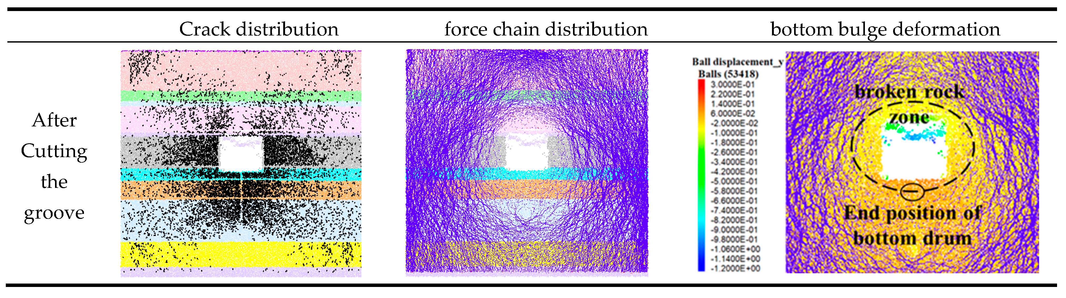
When a single joint is located in the middle of the second floor stratum, the stress characteristics of the surrounding rock after excavation of the 1232 transportation roadway are shown in
Figure 8. Following excavation, stress is released into the roadway, leading to fracture development in the sidewalls, floor, and shoulder areas of the roof, exhibiting a butterfly-shaped distribution. According to the force chain distribution, the loosening zone in the surrounding rock of the roadway is elliptical in shape, with an average extent of approximately 1.5 m on both sides. The thick, silty mudstone in the floor is almost completely fractured, with a failure depth of up to 2.5 m. The fractured mudstone is compacted under lateral load transfer from the sidewalls, forming a load-bearing structure. The floor heave exceeds 30 cm and terminates at the upper boundary of the load-bearing structure formed by the broken silty mudstone. This boundary also corresponds to the edge of the loosening zone in the 1232 roadway’s surrounding rock.
The second layer of the floor stratum is completely damaged under the combined effects of stress release due to excavation and lateral load transfer from the sidewalls. The presence of a single joint in the middle of this layer does not significantly alter the composite beam’s resistance to floor heave deformation. Therefore, when a single joint is located in the middle of the second floor layer, the stress characteristics of the surrounding rock in the 1232 roadway do not exhibit significant changes.
2) Single Joint Located 1 m Below the Top of the Third Floor Stratum
When a single joint is located 1 m below the top of the third floor stratum, the stress characteristics of the surrounding rock after excavation of the 1232 transportation roadway are shown in
Figure 9. the original 4.18-m-thick siltstone layer is divided into two layers with thicknesses of 1 m and 3.18 m. This segmentation reduces the overall resistance of the composite floor beam to floor heave deformation, leading to increased fracture development, expansion of the loosening zone, and intensified floor heave. According to the simulation results, when the joint is located 1 m below the top of the third floor stratum, the surrounding rock of the 1232 roadway exhibits the following stress characteristics: fractures develop in the sidewalls, floor, and roof shoulders, forming a butterfly-shaped pattern; the number of fractures increases compared to previous cases. The loosening zone in the surrounding rock remains elliptical, with an average width of 1.6 m on both sides. Floor failure extends to the stratification layer at a depth of 3.5 m.
(3) Two Joints Located 1 m and 2 m Below the Top of the Third Floor Stratum
When two joints are located 1 m and 2 m below the top of the third floor stratum, the stress characteristics of the surrounding rock after excavation of the 1232 transportation roadway are shown in
Figure 10. the original 4.18-m-thick siltstone is divided into three layers of 1 m, 1 m, and 2.18 m in thickness. This further reduces the composite floor beam’s resistance to floor heave deformation, and theoretically leads to more extensive fracturing, larger loosening zones, and increased floor heave. However, simulation results show that the stress characteristics of the 1232 roadway’s surrounding rock under the condition of two joints at 1 m and 2 m depth are consistent with those under a single joint at 1 m depth, showing no significant changes. The force chain distribution reveals that the horizontal compression between the two joints located at 1 m and 2 m depth forms a hinged structure. This increases the floor’s bearing stress and effectively limits the downward propagation of floor heave, resulting in a maximum heave depth.
As a result, the extent of floor heave shows little difference compared to the case with a single joint at 1 m depth. The fractured rock mass between the two joints forms a compacted structure that constrains further heave, defining the maximum depth range of floor heave, as illustrated in
Figure 11.
As the joints extend deeper into the floor strata, when a joint is located in a layer close to the immediate floor, its influence on floor heave is minimal, since the first floor layer is already completely damaged. However, when the joint is located in deeper strata farther from the immediate floor, and the fractured rock fails to form a compacted, stable load-bearing structure, the extent of floor heave increases. If the fractured rock mass forms a load-bearing structure, it can reduce floor bending and deformation, effectively preventing further downward propagation of the heave. As a result, the maximum depth of floor heave is limited to the upper boundary of the bearing structure formed after rock failure.


