Abstract
The paper presents the dynamics of a 2R planar articulated robot, developed by two original methods. One is the classical “Lagrangian” adapted by the author, and the second method is absolutely original. The dynamics of the robot are based in both cases on the variation of the inertial forces in the mechanism, or practically on the influence of the masses of the moving elements of the robot. The influence of external loads, weights and the load to be transported is also taken into account. Another original element of the work is the choice of speeds in such a way that they correspond to an optimum necessary for the inverse kinematics imposed on the robot. For this reason, the dynamic operation will be quiet and without large variations or vibrations. If the speeds of the two electric motors (preferably stepper motors) areadapted to those recommended by the author, the controller (PID) used will have a very light load. It is even possible to eliminate it if the adjustment of the two stepper motors (actuators) is performed according to the speeds indicated by the author of the paper. The kinematic motion imposed by the indicated optimal speeds is dynamically and successfully checked by both methods used.
1. Introduction
A definition of the physics or mechanics of dynamics says that it is a branch of mechanics (see mechanical meaning 1) that deals with forces and their relationship primarily with motion, but sometimes with the balance of bodies [1]. Dynamics is the discipline that deals with the real movement in any field, with it being the most important movement, a fact for which the dynamic study in mechanics, as well as in other fields, is very important. However, today, dynamics cover a multitude of aspects, starting from the forces in the systems and going to the new technologies and technological processes. A methodology for the flexible implementation of collaborative robots in intelligent production systems is presented in paper [2]. A method of optimizing the robot arm design by using a kinematic redundancy resolution technique is presented in paper [3]. Control of the trajectory of industrial robots using multilayer neural networks driven by iterative control of learning can be found in paper [4]. The dynamic and friction parameters of an industrial robot with the identification, comparison, and analysis of repetitiveness, represent other important aspects of the dynamic and robotic processes in the industry [5]. The impact of gravity compensation on learning-by-consolidation in goal-setting tasks for robotic manipulators is a relatively new issue in dynamic disciplines [6]. Another new dynamic aspect is the mechatronic redesign of a manual assembly workstation in collaboration with wiring assemblies [7], which can be directly associated with the new technological processes.
Another aspect of the dynamic process appears in paper [8] by developing a high-speed, low-latency remote-controlled robot hand system. The educational resources accessible for teaching and learning robotics [9] are also a dynamic aspect, but different from the physical–mechanical one that we are particularly interested in within this paper. Dynamic identification of the parameters of an indication mechanism taking into account the articulated play [10] is a basic dynamic process. The impact of cycle time and payload of an industrial robot on resource efficiency [11] is also an important aspect of dynamic processes. Today, adaptive control of the position (or force) of a robotic manipulator [12,13], as well as the trajectory control [14,15,16,17,18], are important dynamic processes.
There is no need to discuss the importance of the articulated robots studied in this paper because today they represent 90% of the industrial robots used almost everywhere, these articulated robots havethe task of making practically all the components of a car, of moving and maneuvering them, and then assembling them. Industrial robots are automatic, programmable machines with multiple axes of motion that can move to perform a task. An axis of motion is a joint in the body of the robot in which a segment can move. For example, a three-axis robot can rotate at the base, move its arm up and down, and rotate its grip at the end of the arm. They impress with their versatility whichallows them to use new types of application areas. Whether on the floor, ceiling, or wall—thanks to the integrated power supply and the compact control system—such a well-established system offers maximum accuracy in the smallest spaces. Safe-Robot functionality enables innovative automation concepts. Whether it is suitable for rooms with a controlled atmosphere, for areas with a risk of explosion, with a hygienic or splash-resistant design, it is always precise and fast in every model and movement. Whether it is dusty, humid, or sterile environments, such a robot achieves top performance in any environment production. Robots have penetrated everywhere, including the medical area, in the operating rooms [19]. A special issue in the dynamic processes of robots [20,21,22,23] is the study of their kinematics, closely related to dynamics. Another important dynamic aspect [24,25] is the balancing technological processes. The influence of forces [26] is in fact that which determines the dynamic, real operation of all mechanical processes, including robots. In this way, it is possible to control the trajectory of robots and/or aerospace ships (or drones) [27,28,29,30,31,32,33,34,35,36,37]. Mechanical transmissions actively participate in the performance dynamics of robotic technological dynamic processes [38,39]. An important aspect in the study of dynamical systems is the forces of inertia, which can be taken into account by the inertial masses of the system [40,41,42,43].
The main part of a three-axis articulated robot is the two planar movable arms operated by two actors. This simplified system will be taken into account in this paper [19,20,21,22,23]. The optimal trajectories of a robot can be synthesized and controlled only by a predictive, dynamic design, taking into account the dynamic kinematics of the robot [44,45,46,47,48,49,50,51,52,53]. No matter how many degrees of mobility an articulated robotic system has, it will be initially operated by a rotating platform that orients it quickly in space, which is also its spine, then two arms resembling a human hand, i.e., an arm and a forearm, in order to then directly insert the defector, or several additional modules with several degrees of mobility. For this reason, the main part of the system is the arm and forearm, as will be studied in this paper.
The paper will present two original methods of dynamic study of an articulated system with two mobilities, with two actuators (preferably stepper actuators). The working speed proposed by the author for the two actuators will be taken as variable so that all the positions planned within the reverse kinematics trajectory of the articulated robot can be reached. In this way, the dynamic operation will be very close to the designed kinematic one.
The importance of robot dynamics, which is the real workings of robots, has been reflected in many specialized works since the beginnings of modern robotics. In this area of mechanism dynamics, the robotics community has focused particularly on the issue of computational efficiency, with the obvious goal of facilitating dynamic computational methods with the help of computational ones [54,55,56,57,58,59]. Thus, many of the most efficient algorithms in dynamics, which are applicable to a wide class of mechanisms, have also been developed by researchers in robotics [60]. Computational efficiency continues to be important for the simulation and control of mechanisms (that are increasingly complex and that operate at higher speeds), but also other aspects of the problem of contour dynamics that are becoming important today. In this sense, the algorithms must be clearly formulated through a compact set of equations in order to facilitate their development and implementation. In addition, there must be a clear relationship between these equations and the recursive set from which the highest computational efficiency is obtained, which is why the utilization of spatial notations, as well as the algebra of the spatial operator, has increased the efficiency of dynamical systems and especially robots. It is still important to further develop algorithms with a more general character, valid in the dynamics of mechanisms as well as in robots, which have applicability to robotic mechanisms with general geometries and joint structures, which is why, based on the study of such classical systems [44,45,46], the author of this paper wish to present for the first time two new general algorithms for dynamic calculation of mechanisms, with applicability to articulated industrial robots, the most frequently used today in world robotics (in a proportion of over 90% of total industrial robots).
Between the years 2000 and 2008, the novelties in dynamics remained the same as those of the 20th century, using: (1) the Newton–Euler algorithm (NEA); (2) the Lagrange equations, kind I or II; (3) Laplace transformations, or Fourier transformations [42,43,44]. However, there are still some transformations and novelties, such as: (a) the recursive Newton–Euler algorithm (RNEA). This algorithm solves the inverse dynamics problem; (b) the articulated-body algorithm (ABA). This algorithm solves the forward dynamics problem; (c) the composite-rigid-body algorithm (CRBA). This algorithm calculates the joint-space inertia matrix, H. When combined with the RNEA, to calculate c, and a linear equation solver, to solve Hq” = τ − c for q”, the result is an algorithm to solve the forward dynamics problem [48,49,50,51]. For a long time now, the problem of the dynamics and control of the end effector has been raised [52], as it is the most important problem for a robot. In this paper, the new methods presented will refer to the entire dynamics of the robot, studied on all its mobile elements, at any point or coupling of its connection, so including the end effector point, one of the most important. One considers the robot’s kinematics starting from the end effector, so the inverse kinematics imposed by the useful trajectory of the robot. One solves the trajectory imposed simply and originally with the help of logical functions (see Appendix A).
The Mathcad software helps a lot in the correct, precise, simple, direct, and fast solution of all these algorithms and programs (Appendix A). More and more dynamics problems are starting to be solved with the help of specialized software, the most used lately being Matlab with its Simulink subprograms (that help to simulate the theory in real-time). When it comes to simulating the robot commands and control, the Simulink is most desirable, and possibly its subset, “SimMechanics” [53]. Even in these situations, the dynamic methods used remain basic, so this paper has its role well-determined in the realization of methods to study the dynamics of the machines that are more user-friendly and easier to understand and apply. Matrix methods are the most common, including in the calculations of space robots [60].
Frictional contact multibody simulation has been a challenging research topic for the past 30 years. Rigid body hypotheses are commonly used to approximate contact physics and, together with Coulomb friction, lead to difficult-to-solve nonlinear complementarity (NCP) problems. On the other hand, clamping robots often introduce significant compliance. Conforming contact, combined with regular friction, can be modeled entirely with ODE, avoiding NCP solutions. Unfortunately, regular friction introduces rigid high-frequency dynamics and even the default methods struggle with these systems, especially during slip-stick transitions. In order to improve the performance of the default integration for these systems, a transition line search (TALS) can be introduced, which greatly improves the convergence of Newton–Raphson iterations performed by the default integrators. This demonstrates that TALS works best with semi-implicit integration, but that explicit treatment of normal compliance can be problematic. To address this, a TAMSI (Transition-Aware Modified Semi-Default) integrator is being developed that has a similar computational cost to the semi-default methods, but implicitly couples compliant contact forces, leading to a more robust method. The robustness, accuracy, and performance of TAMSI are assessed and the approach is demonstrated along with relevant sim–real handling tasks [60]. In addition to Lagrangian or Hamiltonian mechanics, based today on the (transformed) Laplace or Fourier function, software and dynamic algorithms have increasingly been developed for the command and control of robots and/or aircraft, using modern Neural, Fuzzy, Genetic Algorithms methods, predictive, regressive, robust, closed-loop, or feedforward methods. Controllers today play a key role in command, controlling, and automating machine dynamics, and among other issues they raise are the dynamic programs and algorithms of the machine that need to be programmed, commanded, and controlled [47,52].
Reinforcement learning (RL) is promising for complicated nonlinear stochastic control problems. Without using a mathematical model, an optimal controller can be learned from data evaluated according to certain performance criteria by trial and error. However, the data-driven learning approach is renowned for not guaranteeing stability, which is the most fundamental property of any control system. For these reasons, Lyapunov’s classical method of system stability is further studied and explored to analyze the uniform final limit stability (UUB) exclusively on the basis of data, without using a mathematical model. In this way RUB with a UUB guarantee can be applied for the control of dynamic systems with safety constraints. As a result, optimal controllers can be learned to guarantee the UUB of the closed-loop system both at convergence and during learning. The proposed algorithms are evaluated on a series of robotic tasks of continuous control with safety constraints. Compared to existing RL algorithms, the proposed method [61] can achieve superior performance in terms of maintaining safety. The actuators implemented on the respective system also have an important role in achieving the dynamic stability of a robot [62].
The dynamic stability of the robotic system also depends to a large extent on the way the actuator speeds are chosen. The present paper aims to bring superior stability to robotic systems based on the imposition of controlled speeds (see Section 5 of the paper). In this sense, two new methods of imposing actuator speeds are adapted, regardless of whether they are linear or rotational. The calculations in both situations (variants) are based (like the methods) on the numerical derivation by developing the functions in a Taylorseries. The closed-loop control that is usedtoday in all robotic systems brings major advantages in the dynamics of that system, and due to the change of actuators parameters based on real-time data provided by a lot of sensors (including visual and proximity) mounted on the robotic system [62]. Even so, with the use of servo motors, or the use of stepper actuators, which bring high precision and permanent active control, the use of advanced software in robotic systems based on simple and efficient dynamic algorithms has greater advantages in stability, dynamics of the system, and in its natural behavior, achieving an optimal function without vibrations and noises, with high offset speeds, and with high precision, following exactly the trajectory imposed by the inverse kinematics.
2. Methods
2.1. First Dynamic Proposed Method
The first original dynamic proposed method presented in the paper is a classic, improved one. The articulated robot mechanism with two degrees of mobility that is studied can be observed in Figure 1. The two movable elements 1 and 2, with a flat motion of the articulated robot, are actuated by two stepper actuators 1 and 2, respectively.
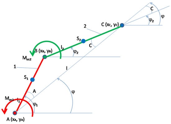
Figure 1.
The articulated robot mechanism with two degrees of mobility.
In the approximate classical dynamics, the variable angular velocities and the variable angular accelerations are determined; the variation is due to the forces of inertia or the variation of the masses of the moving elements (Figure 2).
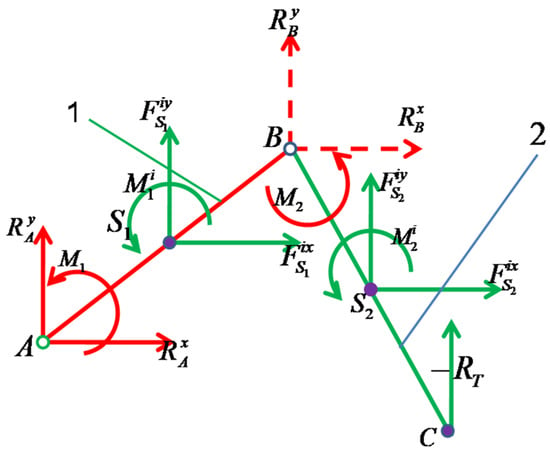
Figure 2.
In the approximate classical dynamics, the variable angular velocities and the variable angular accelerations are determined; the variation is due to the forces of inertia.
The calculation relationships are further presented in system (1). The calculations were performed in Mathcad and can be traced more closely in Appendix A. represents the mass moment of inertia of the entire robot reduced (*) to element 1 in point A (kinematic coupling A). It takes the place of the rotating mass of the entire robot around the coupling A on element 1 and can represent the dynamic model of the entire robot reduced to element 1 in the active coupling A, so that it can generate the dynamic parameters of this element 1 (such as: w1, eps1). Its equation is obtained simply by conserving the kinetic energy of the entire machine (robot). Similarly, the expression of the rotating mass () of the machine (robot) considered (reduced, *) at element 2 in the kinematic couple (motors) B is deduced. This simple, original, and efficient dynamic system is deduced by conserving the kinetic energy of the entire machine (robot) and behaves somewhat similar to that achieved by using the Lagrange dynamic equation of the second kind. It is applied separately to each mobile element, and not only to the driving elements. Thus, in order to determine the dynamic parameters of element 1, after determining the variable rotating mass of the entire system (machine, robot) reduced to element 1, the variable (dynamic, real, angular) velocity of element 1 (), is then determined. The quick method presented (Equation (1)) is an original one [38,39]. Another completely new method is presented in Section 2.2 of this paper, with slight advantages in terms of accuracy, but with major disadvantages in terms of its generality.
Observation: All units of measurement used are those given by the international system.
JS1 is the rotational mass of element 1 determined in its center of mass S1 about an axis perpendicular to the plane of the mechanism at point S1. It is generally denoted by the mass (or mechanical) moment of inertia of element 1 determined in its center of mass S1. JS2 is the rotational mass of element 2 determined in its center of mass S2 about an axis perpendicular to the plane of the mechanism at point S2. It is generally denoted by the mass (or mechanical) moment of inertia of element 2 determined in its center of mass S2. m1 represents the mass (classical in translation) of element 1, while m2 is the mass of element 2. ω1m is the average rotational speed of element 1, and similarly, ω2m is the average angular velocity of element 2; ω1 is the rotational speed of element 1, and similarly, ω2 is the angular velocity of element 2; ω1D is the dynamic (real) rotational speed of element 1, and similarly, ω2D is the dynamic angular velocity of element 2. and represent the scalar components along the x and y axes, respectively, of the linear velocity of element 1 at point S1 (center of mass of the element). Where and represent the scalar components along the x and y axes, respectively, of the linear velocity of element 1 at point S2 (center of mass of the element).
There are two original basic aspects in the presented method: (1) the generalized way in which the moments of mass inertia of the whole mechanism are written, reduced to any of the desired elements of the machine, using the kinetic energy conservation equation of the whole mechanism; (2) the generalized way in which the angular velocities of each element of the mechanism are determined by using an original relation already presented in previous work [38,39], now repeatedly for each element of the machine, in this case of the simple articulated robot. For a better understanding of this original dynamic method with wide use, the author presents it in the paper and applies it to another type of robot in Section 4. For element 1, the moment of reduced mechanical inertia in joint A is determined, and for element 2, the moment of reduced mechanical inertia in joint B is determined. The classical dynamic angular velocity of each actuator (w1, w2) is determined according to the kinematic angular velocity and the variation of the respective moment of inertia (1, or 2) reduced to its joint (A or B). The method is simple, straightforward, and original [38,39]. Dynamic angular accelerations are determined directly from the angular velocities by approximate numerical derivation (using the Taylor series development). The solution ofsolving Lagrange’s equations of the second kind (here being two degrees of mobility, so two independent variables) generates larger errors, and for this reason, we resorted to the method of finding direct angular accelerations based on dynamic, real angular velocity values [38,39].
Figure 3 and Figure 4 show the variations of mass (mechanical) moments of inertia (JAred, or JBred [kg·m2]) reduced to a coupling A (element 1), and B (element 2), depending on the independent variable (k) initially chosen in the program, which in turn may depend on the rotation angle of elements 1 and 2, respectively, or directly on the time t (see the program written in Mathcad, in Appendix A).
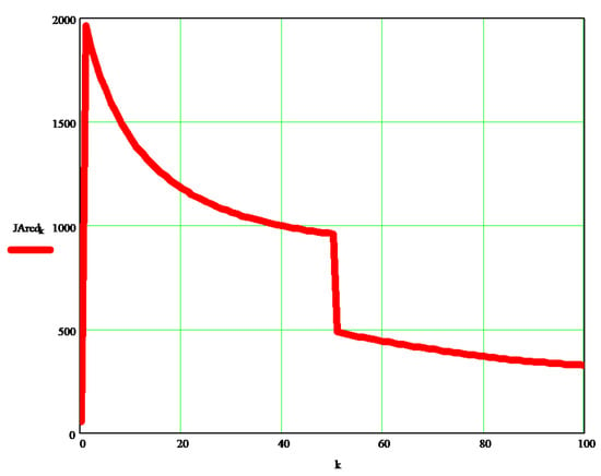
Figure 3.
Variations of mass (mechanical) moments of inertia reduced to a coupling A (element 1).
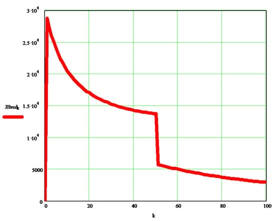
Figure 4.
Variations of mass (mechanical) moments of inertia reduced to a coupling B (element 2).
Figure 5 shows the variation of the dynamic angular velocity 1 (w1D [s−1]), depending on the independent parameter k.
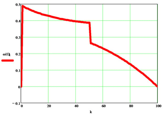
Figure 5.
Variation of the dynamic angular velocity 1, depending on the independent parameter k.
Figure 6 shows the variation of the dynamic angular velocity 2 (w2D [s−1]), depending on the independent parameter k.
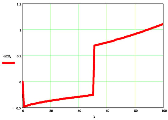
Figure 6.
Variation of the dynamic angular velocity 2, depending on the independent parameter k.
Figure 7 shows the difference between the kinematic speed and the classical dynamic speedof the mobile element 1 of the robot.
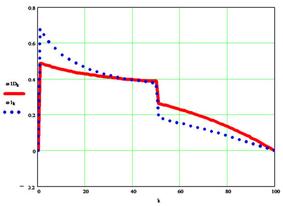
Figure 7.
Difference between the kinematic speed and the classical dynamic speedof the mobile element 1 of the robot.
Figure 8 shows the difference between the kinematic speed and the classical dynamic speedof the mobile element 2 of the robot.
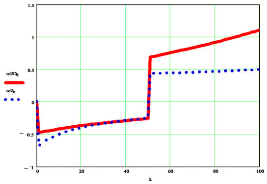
Figure 8.
Difference between the kinematic speed and the classical dynamic speedof the mobile element 2 of the robot.
2.2. Second Original Dynamic Proposed Method
The second original dynamic method presented in the paper uses the same Figure 1 and Figure 2. The basic idea is a simple one, namely, if the dynamic variations of the angular velocity belonging to a moving element compared to the desired kinematic velocity actually depend on the variation of the forces in the robot mechanism, then they will be determined based on the forces of the whole mechanism considered, without the moving elements being separated from each other or by the external input couplings, i.e., without loosening the connections (Figure 2). One starts from the simple calculation relations (2):
In the first relation, whichrepresents the sum of the forces acting in the machine only on the abscissa axis (x-axis), we meet the inertia forces in the system concentrated in the centers of mass S1 and S2, respectively, oriented on the x-axis. In the second relation, whichrepresents the sum of the forces acting in the machine only on the y-axis, we meet the inertia forces in the system concentrated in the centers of mass S1 and S2, respectively, oriented on the y-axis, and the technological endurance RT, the force which the machine must bear or overcome during the active working period; m1 represents the mass of element 1, and m2 that of element 2; ω1 represents the angular velocity of element 1; ω2 represents the angular velocity of element 2; ε1 represents the angular acceleration of element 1; ε2 represents the angular acceleration of element 2; S1 = AS1 and S2 = BS2 represent the distances to the centers of mass of elements 1 and 2, respectively; l1 = AB and l2 = BC represent the lengths of the two elements 1 and 2, respectively.
The system in (2) develops and takes the shape of (3):
The system of two equations in (3) is rewritten using the notations in (4) so that one arrives at a linear differential system of two equations with two unknowns, dw1 and dw2, which are then solved simply (see Equation (5) written in Mathcad); it is basically a finite difference method. The angles ( and ) position elements 1 and 2, respectively, with respect to the x-axis (abscissa axis; Figure 1); g is the gravitational constant; all sizes used are those of the international standard. In order to be able to express the very long equations, the notations N1 and N2 were used for the numerator of the two fractions, and the notations n1 and n2 for the denominator of each of the two fractions (in the equations system (5)). The new equations used (in the second method presented) are with finite differences and have the great advantage of transforming the unknown ωD into a sum ω + dω, in which ω is the precisely known angular velocity, in most cases it being a constant average value that depends on the speed of the respective actuator, which operates the element in question, while the new unknown obtained by the simple transformation with finite elements is dω, and its value is easily obtained from the corresponding equation, which in this way is linearized. In this way, the problem of the nonlinear dynamical system is solved directly, which is otherwise solved by using a Laplace or Fourier transform twice, or by using the Lagrange equations of the second kind. The advantages of the method presented and proposed in the paper are obvious. The real, nonlinear dynamic system is directly linearized, by using this new method with finite differences, the proposed equations are simple and direct, very precise, and easy to learn from a didactic point of view, but also simple to use by researchers. The proposed new systems (both new methods presented in the paper) have a high utility and high applicability, but the second method (with finite differences) is simpler and more direct, while the first proposed method has the great advantage of high generality so that it can be applied to any machine, robot, system, without prior preparation, where cg can take only the value 1 (system with the influence of gravitational forces) or 0 (system without the influence of gravitational forces);
where: .
Note: If one wants to eliminate the effect of gravitational forces then to the cg coefficient is assigned the value 0 instead of 1 (for example, when the robot, instead of operating in a vertical plane, works in a horizontal plane). FV is a velocity factor (see Section 5). Asthe second method presented in the paper, which has all the new elements, being an absolute novelty, has a lower generality, it can be applied to any important system by adapting equations (rewriting Equations (3) and (5)).
3. Results and Discussions
The original dynamic angular velocity w1d [s−1] can be seen in the graph in Figure 9, and the differences between it and the kinematic velocity w1 [s−1] are visible in the diagrams in Figure 10.
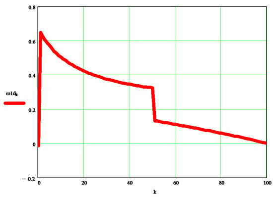
Figure 9.
The original dynamic angular velocity w1d.
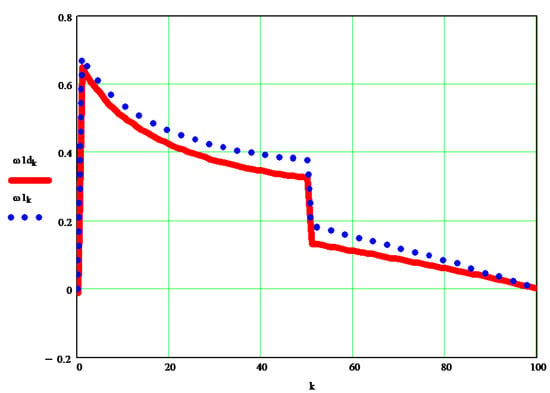
Figure 10.
The differences between angular dynamic velocity w1d and the angular kinematic velocity w1.
The original dynamic angular velocity w2d [s−1] can be seen in the graph in Figure 11, and the differences between it and the kinematic velocity w2 [s−1] are visible in the diagrams in Figure 12.
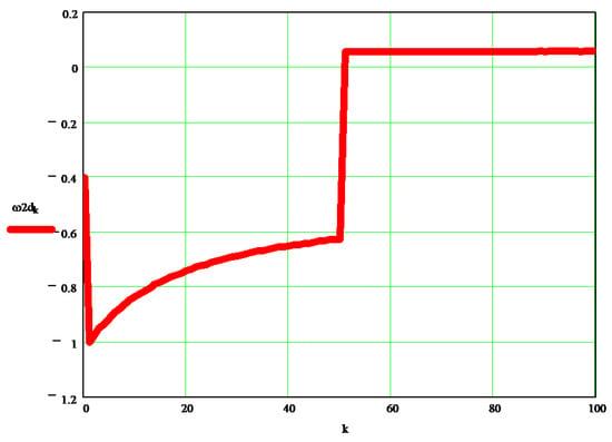
Figure 11.
The original dynamic angular velocity w2d.
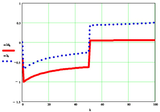
Figure 12.
The differences between angular dynamic velocity w2d and the angular kinematic velocity w2.
For a comparison between the dynamic speed wd obtained by the original method presented and the dynamic speed wD obtained through the classically improved method, the diagrams in Figure 13 and Figure 14 will be followed, for elements 1 and 2, respectively.
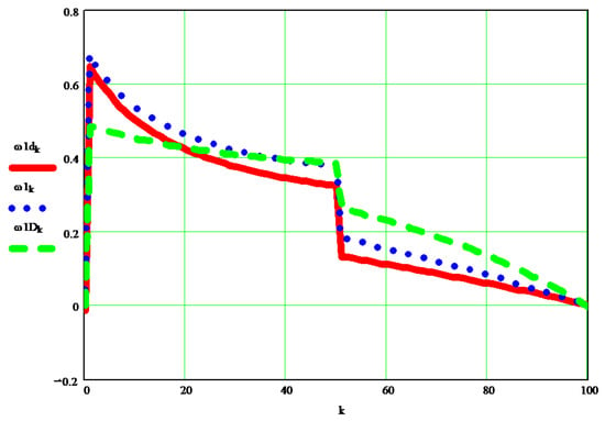
Figure 13.
A comparison between the dynamic speed w1d [s−1] obtained by the original method presented, and the dynamic speed w1D [s−1] obtained through the classically improved method.
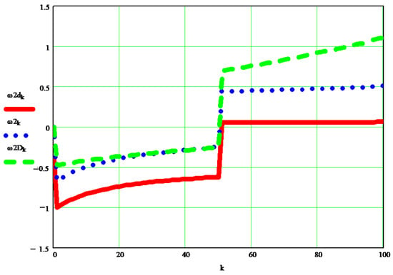
Figure 14.
A comparison between the dynamic speed w2d [s−1] obtained by the original method presented, and the dynamic speed w2D [s−1] obtained through the classically improved method.
The classical method modified by the author uses the moments of mechanical or mass inertia reduced to the mobile element at which the calculation of the dynamic speed is made, reduced even in the torque that acts on the respective element. An older original calculation system was also adopted, for obtaining directly approximate dynamic angular velocities. A very exact method can be used here, even if it is approximate, presented by the author in the papers [38,39], but in this case, the calculations become extremely difficult and cumbersome, with the final differences compared to the first method presented in this article being small. All three results are close enough, even if they are obtained by three totally different calculation methods, and this specifies that the dynamics of the system is a normal, quiet one, based on the fact that the kinematic speeds imposed on the system were chosen by an original method designed to improve the operation of the robot; a method that aims to ensure that the kinematic parameters imposed (in the inverse kinematics) to the robot are all tracked and achieved in operation. If the kinematic speeds change, for example by adopting someone’s constants, the dynamics obtained by both presented methods will be broken, and the real operation of the system will worsen. The fact that both methods presented give similar results indicates the correctness of both methods used in system dynamics.
4. First Original Proposed Dynamic Model Applied to a 2T6R Robot
The articulated robot from Figure 15 will be briefly presented, which in this situation is operated with two linear actuators (elements of variable length 3 and 4, respectively) instead of the two classic rotary actuators. In this way, the robot mechanism will have six moving elements instead of two; however, to facilitate the study the two linear actuators, formed each of two elements of constant length, will be considered as a single moving element of variable length, so that the six mobile elements of this robot will be reduced in the study to only four mobile elements.
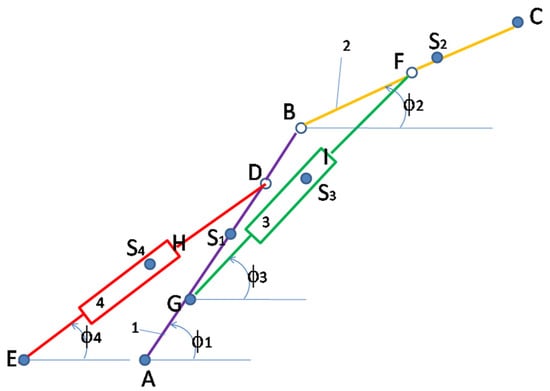
Figure 15.
A simple articulated robot, operated with two linear actuators (a 6R2T robot).
The kinetic energy of the whole mechanism is conserved (Equation(6)) [38,39]:
represents the kinetic energy of the whole machine, an element that is preserved; m1 = mass of element 1; m2 = mass of element 2; m3 = mass of element 3; m4 = mass of element 4; is inertia mass of element 1 in the mass center; is inertia mass of element 2 in the mass center; is inertia mass of element 3 in the mass center; is inertia mass of element 4 in the mass center; ω1, ω2, ω3, ω4 represents the rotational speed of the respective element (1, 2, 3, 4); the velocity of the center of mass of element 1 (S1) projected on the x-axis; the velocity of the center of mass of element 1 (S1) projected on the y-axis; the velocity of the center of mass of element 2 (S2) projected on the x-axis; the velocity of the center of mass of element 2 (S2) projected on the y-axis; the velocity of the center of mass of element 3 (S3) projected on the x-axis; the velocity of the center of mass of element 3 (S3) projected on the y-axis; the velocity of the center of mass of element 4 (S4) projected on the x-axis; the velocity of the center of mass of element 4 (S4) projected on the y-axis.
The second robot presented in the paper is in fact the first robot, operated differently, instead of rotary actuators, it has two linear actuators, which introduce into the robot system four more moving elements, two for each linear actuator, so that the configuration of the robot changes radically, and it is now being studied as if it were another system. Asthe first new method presented in the paper has a more general character, we applyit here to this second robot, it being practically similar to the one already written for the first robot but generalized by extension to several mobile elements. Instead of two mobile elements, the new robot has six, so as not to introduce so many extra mobile elements, we chose the situation in which each actuator is considered only as one additional mobile element, but of variable length, so that the two linear actuators introduce only two additional moving elements and the presented robotic system has a total of four moving elements. For this reason, the new equations presented (6)–(14) in “Dynamic Method 1” will be extended from two to four moving elements.
This is the first new dynamic method of the paper, which we will explain in detail here, and one starts with the kinetic energy of the entire robot (machine; Ekinetic) which is known to be conserved, but the equation used (6) is in fact that of twice the kinetic energy of the machine (2·Ekinetic); obviously if it is conserved (kinetic energy) thenits double is a constant throughout the operation of the machine, regardless of the position of the angles that position each moving element, and regardless of the actuators working speed (in this case being two linear actuators).
The originality of the dynamic method 1 proposed in the paper is how to determine the moments of mass (mechanical) inertia for each element, in order to reduce the mechanism to a single element (any of them) so that a dynamic model of the machine with an only one element can represent (replace) the dynamics of the whole machine (robot). Using successively Relation (6) (four times), for each element of the robot mechanism, one obtains the four equations that generate the moments of mechanical inertia (mass) reduced successively to each of the four elements (Equations (7)–(10)).
This method has long been known and often applied in the Romanian school of mechanisms [45,46], but only for a single mobile element, namely the motor, and only to machines with a single degree of mobility, after which was used the Lagrange differential equation of kind one for solving the nonlinear, dynamic system, with a single input with two unknowns, ω, and ε. The proposed new method has generalized the determination of a dynamic inertia mass of the whole mechanism for (reduced to) each mobile element of it, regardless of whether it is a direct motorized one or not, in order to obtain, at each element, a basic dynamic parameter on the basis of which the dynamics of that element of the machine (robot)can later be described. In the case of the robot presented with four moving elements, it results in four rotating masses (, , ,), each reduced to one of the four moving elements of the robot (Equations (7)–(10)). In order to further solve the dynamics of each moving element of the machine, different methods can be used. A classic method would be to use the Lagrange dynamic equation of kind one, which the author has already described and applied to other types of mechanisms [39], with an original solution by the finite element method, somewhat similar to the one proposed in the second presented dynamic method of the paper. At this stage, it was decided to use a simpler method, presented for other machines in other works [38,39], which directly solves the dynamics of the machine without using differential equations. This method applies simply, directly, to each moving element (Equations (11)–(14)), to solve the dynamic of any machine mobile element. Each rotating mass of the whole machine reduced to a certain mobile element carries in it the dynamic characteristic of the whole machine reduced to that element and depends both on the positions occupied by the machine during operation and on the speeds of the actuators.
Below are the dynamic values of the angular velocities of each element in relation to Equations (11)–(14), which is the second original element of the dynamic method 1 proposed in the paper [38,39]:
This fast and accurate, but especially simple, method of determining the dynamics of any machine is based on a classic idea of conserving the kinetic energy of the whole machine applied twice, in two steps (through two passes).
For the second step (applied here in particular to the robot with two linear actuators), the conservation of the kinetic energy of the machine, written in the form of Equation (15), is also used.
The absolutely original Equation (15) is easily applied to any dynamic system, the machine (robot) if it is known for any desired element of the machine, but which also has rotational motion, its average kinematic rotational speed ωm, and the rotational mass of the whole machine reduced to the respective element J*. Thus, the reduced angular velocity (dynamics) ω* = ωD of the respective element is easily determined, provided that the average value of J*, i.e., is also found.
The proposed new method has a strong general character (the one most desired aspect), a high degree of applicability, ease of understanding and development, simplicity, efficiency, and directness. With its help, the real (dynamic) angular velocities of the machine can be determined with great precision, for any of its elements, in the case proposed for any of the 4 elements of the 6R2T robot presented (in Figure 16). The dynamic speeds of the discussed 2T6R robot obtained with the help of the new proposed Equations (11)–(14), will be presented in Figure 16, Figure 17, Figure 18 and Figure 19, (in each of them the dynamic angular speed obtained iscompared with the static one given).
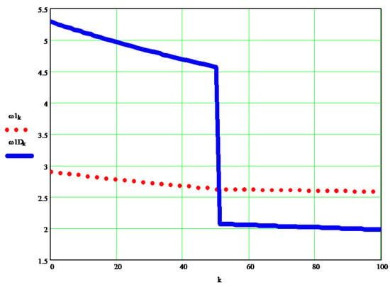
Figure 16.
The dynamic angular speed of element 1 of the articulated robot, compared to the input (kinematics) considered speed (to a 6R2T robot).
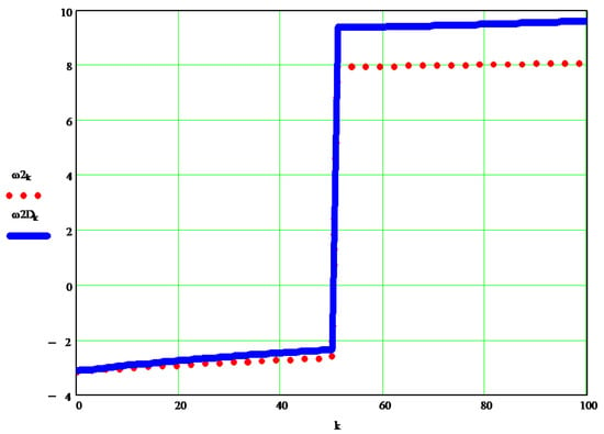
Figure 17.
The dynamic angular speed of element 2 of the articulated robot, compared to the input (kinematics) considered speed (to a 6R2T robot).
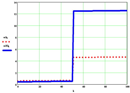
Figure 18.
The dynamic angular speed of element 3 of the articulated robot, compared to the input (kinematics) considered speed (to a 6R2T robot).
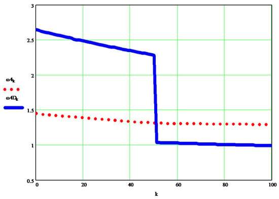
Figure 19.
The dynamic angular speed of element 4 of the articulated robot, compared to the input (kinematics) considered speed (to a 6R2T robot).
The second original dynamic method proposed in the paper and presented briefly has the advantage of taking into account all the forces acting in the machine, but it is a method with a weak general character, requiring particular study for each case considered so that the calculation relations presented in a premiere have a character limited only to the mechanism of the simple articulated robot with two moving elements actuated with two rotary actuators. For another drive or another type of robot or machine, it is necessary to restore the calculation relations, so the method is difficult and has great importance only when you want to determine very precisely the dynamic parameters of an important machine, such as the articulated robot considered because it is being implemented more and more in today’s industries.
5. Speed Command and Control
The command and control of speeds are achievedby the author by two different methods, both with real advantages. The first method of command and control of speeds refers to keeping the engine speeds constant so that their accelerations are zero or very low, and the movement of the elements of the machine, the robot, areperformedquickly, with good dynamics, and are easy to control. As the motor speeds of a robotic machine, or other machines, even if they are generally constant, must change the sign depending on how the actuator element moves (for both linear and circular displacement), the constant engine speeds are taken but with a changeable sign, the sign being given by the positions occupied successively by the mechanism. In this way, the intelligent command and control of the speeds are realized, with their automation. The simple sequence used to automate angular velocities in a robot with two motors can be traced in Relations (16), it iswritten using the “if logic” function.
The modulus of a speed (w) is constant, and its sign is given by the finite displacements already known (in inverse kinematics these displacements areimposed by the necessary position of the endeffector, they aresolved most easily with the help of “if logic” functions).
The second method of command and control of speeds refers to the application of permanently variable speeds to the actuators, these speeds being those obtained from the approximate numerical derivation of the already known robot positions imposed (by the inverse kinematics). For the simplest numerical derivation, the finite element known method obtained by developing the position functions in the Taylor series was considered (Equation (17)).
The reduced speeds of the actuators are obtained based on the approximate numerical derivation of the positions (by developing the Taylor functions), they are variable in size and sign depending on the imposed and known positions (from inverse kinematics), and the absolute speeds are obtained by amplifying the reduced ones with a constant “velocity factor” (FV), chosen according to the time required to complete the respective race. Even though the two methods have similar sequences, they are completely different. In the first method, the finite positional differences impose only their sign and the speed of the respective actuator, the speed of the module being a chosen constant w, and in the second situation (method 2 presented), the finite differences of the positions impose both their sign and their value absolute of the respective actuator, which will result in this variable mode as well as the module, and which will be obtained from the reduced speed given by the finite positions by the amplification with a factor of speed (or time), FV.
6. Future Works
The dynamic model (Section 2.1 and Section 4) can be easily resumed and presented on various other machines, including robotic systems, due to its generality, and simple and direct applicability. The author intends, in future works, to analyze and customize the second new dynamic method proposed in the paper (Section 2.2) for other types of machines and or robots, depending on their industrial importance. The author also would also like to continue to try to use the Matlab and Simulink programs instead of (or with) Mathcad simulation, in order to directly determine the command and dynamic control of mobile mechanical systems, with their automation.
7. Conclusions
The stability of moving systems today is due to the increasingly high-performance controllers, based on micro-, and recently, nanoprocessors, in the command and control software imposed on the system, usually a discrete or even continuous, robust PID controller, which makes a closed-loop with the help of the software and the constants determined based on the dynamics of the respective system, but more and more it is switched to mechanical systems with mixed control, in a closed-loop plus feedforward system. For this reason (for the very precise establishment of the operating constants and for the adjustment of the PID controller), it is necessary to know the dynamic parameters of the machine in question, a fact for which the present work is extremely important for determining the dynamic parameters of any mobile element of the respective machine, by using both methods presented in the paper.
The two new methods presented in the paper, both theoretically and simulated in Mathcad, are original, easy to understand and use, the first having a very strong generalized character, with the second, having the possibility of generating high precision dynamic solutions, being a method customized to the mechanism, which takes into account all the forces acting on it (but such a conclusion cannot be verified without experiment). The author wants to further implement these methods in other machines and robots and simulate them through Matlab software and its Simulink extension.
A special problem of these dynamic aspects, stability, command, control, and automation, is the command and control of speeds, depending on whether or not the system acquires intrinsic stability, increasing its ability to follow the trajectory imposed on the endeffector by inverse kinematics. The paper presented in Section 5 two new original methods of speed control of a mobile mechanical system, from the beginning, by imposing on all actuators certain speeds, constants, or variables according to intrinsic laws, deduced with the help of Taylor series decompositions of the speed control functions of the machine actuators.
It should be noted here that the novelties of the dynamic system can facilitate the work of a programmer of a controller, for example, a PID, by the fact that the new dynamics imposed by method 1 presented in the paper, can directly solve nonlinear systems, thus eliminating the classic methods where: first, make a linearization, work with the new linear function, and finally delimit the results obtained. The use of Fuzzy methods required an initial fusion and, finally, the defuzzification of all output data, similar toother neuro methods, or genetic algorithms. Method 1 presented in the paper automates this process, making the programmer’s job easier. On the other hand, the method presented allows the use of models of a continuous PI-PID controller, in which all parameters are easy to find, while in classical dynamic methods strongly nonlinear systems of this kind involve the use of a discreet PID controller which is difficult to apply and quantify.
The paper studies two mechanisms corresponding to the same articulated robot with two moving elements, operated in two different situations: (1) with two rotary actuators; (2) with two linear actuators.
Funding
This research has not yet received external funding.
Institutional Review Board Statement
Not applicable.
Informed Consent Statement
Not applicable.
Data Availability Statement
Not applicable.
Conflicts of Interest
The author declares no conflict of interest.
Nomenclature
m is the mass of an element in linear motion and is measured in kg; J is the rotational mass of an element (known as the moment of mass or mechanical inertia) and is measured in kg·m2; ϕ or φ is a position parameter that defines the position angle of an element relative to the abscissa axis and is measured in rad; ω is the angular velocity with which a certain element rotates and is measured in Hertz or s−1; is the mass or mechanical inertia of the mobile element 3 determined around the axis of rotation passing through the center of mass noted with S3 (kg.m2); J* is the mass or mechanical inertia of machine (of all mechanism, or robot) reduced to one single element (an element which must also have a rotational motion in the considered plane) [kg·m2]; the velocity of the center of mass of element 3 (S3) projected on the x-axis [m/s]; the velocity of the center of mass of the mobile element 3 (S3) projected on the y-axis [m/s].
Appendix A
Reverse kinematics on a 2R planar robot.
- (1)
- Establishing the desired coordinates of the trajectory of the endeffector C
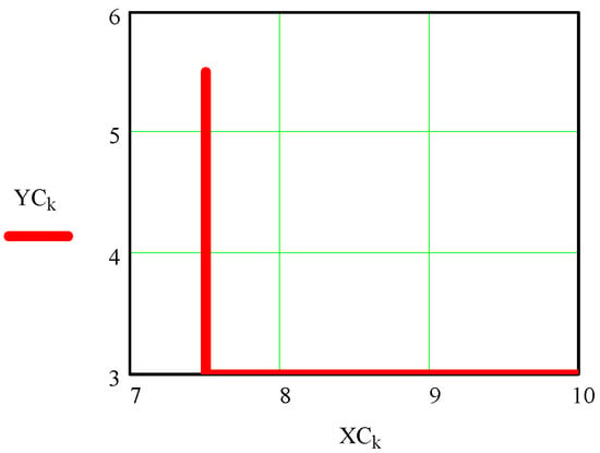
Figure A1.
The hodograph of the end effector point C is the trajectory described by the end effector C.
Reverse kinematics on a planar 2R robot.
- (2)
- Determining the scalar parameters of the kinematic coupling B
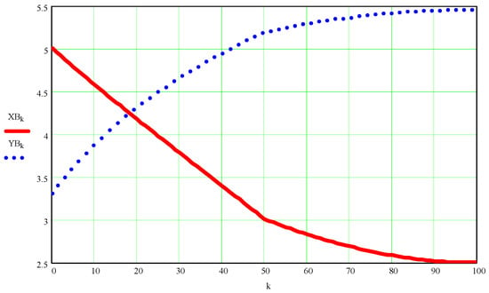
Figure A2.
Scalar coordinates of kinematic coupling B as a function of the independent variable k.
Reverse kinematics on a 2R plane robot.
- (3)
- Determining the angles Fi1 and Fi2
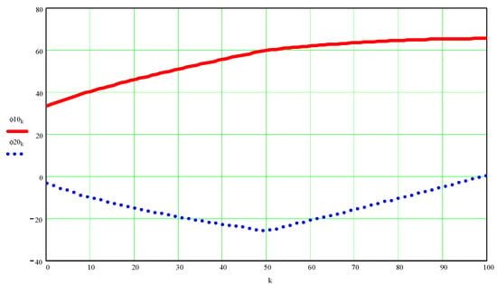
Figure A3.
Values of angles ϕ1 and ϕ2 (in hexadecimal degrees) as a function of the independent variable k.
Reverse kinematics on a 2R plane robot.
- (4)
- Determination of linear and angular velocities and accelerations
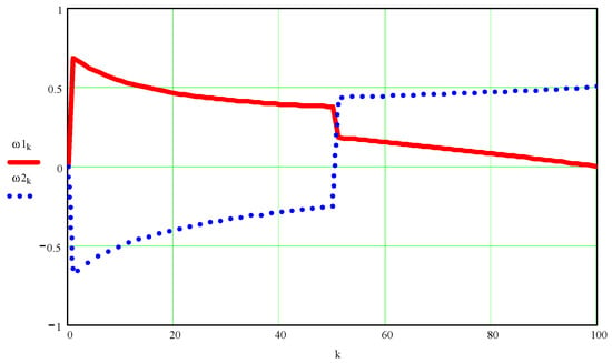
Figure A4.
Values of angular velocities ω1 and ω2 (in hertz) as a function of the independent variable k.
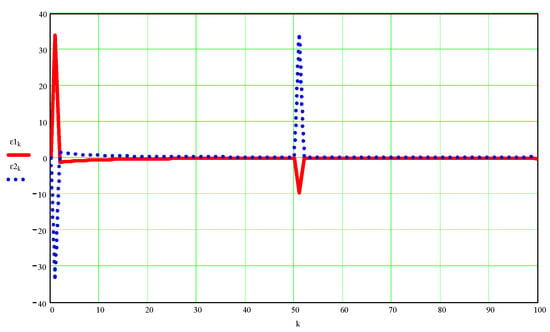
Figure A5.
Values of angular accelerations ε1 and ε2 (in hertz2) as a function of the independent variable k.

Figure A6.
On the left side are the scalar coordinates of the speed of point B (red and blue) and its absolute speed (green); on the right the graphs of the accelerations of the same point B.

Figure A7.
On the left side are the scalar coordinates of the speed of point C (red and blue) and its absolute speed (green); on the right the graphs of the accelerations of the same point C.
Reverse kinematics on a 2R plane robot.
- (5)
- Determining the positions, speeds, and accelerations of the centers of mass S1 and S2

Figure A8.
On the left are the absolute velocities of the center of mass of element 1 (red) and that of element 2 (blue); on the right the graphs of the absolute accelerations of the same points S1 and S2 respectively.
- (6)
- Inverse kinematics in a 2R robot plane (6) Kinematics (forces and motor moments in the mechanism are determined)
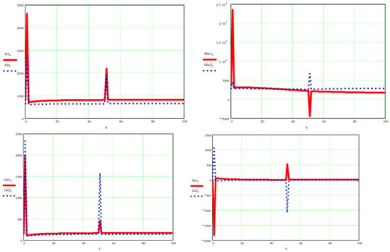
Figure A9.
On the left are represented above the forces in the kinematic couples A (red) and B (blue) and below the inertial forces on element 1 (red) and 2 (blue), and on the right are the graphs of the motor moments at the top (red for element 1 and blue for element 2) and those of moments of inertia at the bottom.
- (7)
- Approximate classical dynamics (variable angular velocities and variable angular accelerations are determined; variation is due to inertial forces or variation in the masses of moving elements), Section 2.1.
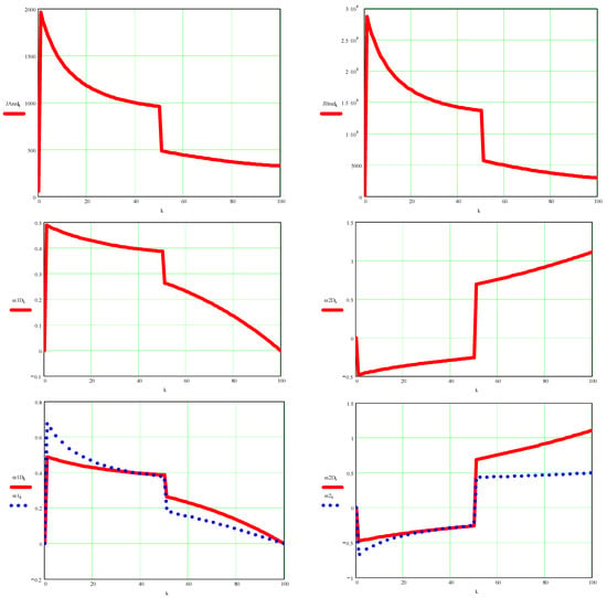

Figure A10.
In the figure you can see above the moment of reduced mass inertia in the coupling A element 1 (left) and in the coupling B element 2 (right), then immediately below are represented the real, dynamic angular velocity of the element 1 (on the left) and of the element 2 (right), immediately below you can see the comparative graphs between the dynamic and kinematic angular velocity for element 1 (left) and element 2 (right), and below you can finally see the comparative graphs of the dynamic angular accelerations and kinematics for element 1 (left) and for element 2 (right).


Figure A11.
Here are represented the velocities of point B in their scalar coordinates (with red for the x-axis and with blue for the y-axis) and in absolute value (with green), dynamic on the left and kinematic on the right, at the top, and below are similarly represented the accelerations corresponding to the same point B.
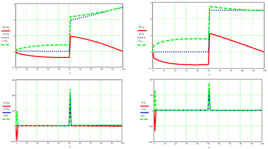
Figure A12.
Here are represented the velocities of point C in their scalar coordinates (with red for the x-axis and with blue for the y-axis) and in absolute value (with green), dynamic on the left and kinematic on the right, at the top, and below are similarly represented the accelerations corresponding to the same point C.
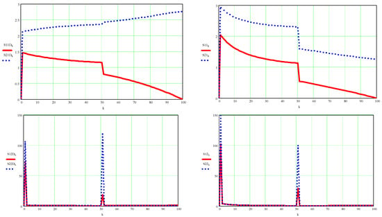
Figure A13.
Here are represented the absolute velocities of point S1 (in red) and point S2 (in blue) dynamic on the left and kinematic on the right, on the top, and below are similarly represented the absolute accelerations corresponding to the same points S1 and S2 also dynamic values on the left and kinematic values on the right.
- (8)
- Original new dynamics (variable angular velocities are determined); Section 2.2.
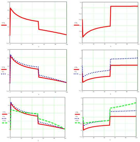
Figure A14.
In the upper part are represented the dynamic angular speeds obtained with the new method presented in the paper, marked with d, on the left for the motor element 1 and on the right for the motor element 2; then below you can see the same dynamic speeds compared to the kinematic ones; in the end, bottom, all three will be compared, ie the dynamic angular velocity obtained by the absolutely new method (d), the kinematic angular velocity, and the dynamic angular velocity (D) determined by a classical method substantially improved by the author.
References
- Merriam-Webster. Definition of Dynamics (Entry 1 of 2); Merriam-Webster: Springfield, MA, USA, 2022; Available online: https://www.merriam-webster.com/dictionary/dynamics (accessed on 21 March 2022).
- Giberti, H.; Abbattista, T.; Carnevale, M.; Giagu, L.; Cristini, F. A Methodology for Flexible Implementation of Collaborative Robots in Smart Manufacturing Systems. Robotics 2022, 11, 9. [Google Scholar] [CrossRef]
- Maaroof, O.W.; Dede, M.I.C.; Aydin, L. A Robot Arm Design Optimization Method by Using a Kinematic Redundancy Resolution Technique. Robotics 2021, 11, 1. [Google Scholar] [CrossRef]
- Chen, S.; Wen, J. Industrial Robot Trajectory Tracking Control Using Multi-Layer Neural Networks Trained by Iterative Learning Control. Robotics 2021, 10, 50. [Google Scholar] [CrossRef]
- Hao, L.; Pagani, R.; Beschi, M.; Legnani, G. Dynamic and Friction Parameters of an Industrial Robot: Identification, Comparison and Repetitiveness Analysis. Robotics 2021, 10, 49. [Google Scholar] [CrossRef]
- Fugal, J.; Bae, J.; Poonawala, H. On the Impact of Gravity Compensation on Reinforcement Learning in Goal-Reaching Tasks for Robotic Manipulators. Robotics 2021, 10, 46. [Google Scholar] [CrossRef]
- Palomba, I.; Gualtieri, L.; Rojas, R.; Rauch, E.; Vidoni, R.; Ghedin, A. Mechatronic Re-Design of a Manual Assembly Workstation into a Collaborative One for Wire Harness Assemblies. Robotics 2021, 10, 43. [Google Scholar] [CrossRef]
- Yamakawa, Y.; Katsuki, Y.; Watanabe, Y.; Ishikawa, M. Development of a High-Speed, Low-Latency Telemanipulated Robot Hand System. Robotics 2021, 10, 41. [Google Scholar] [CrossRef]
- Pozzi, M.; Prattichizzo, D.; Malvezzi, M. Accessible Educational Resources for Teaching and Learning Robotics. Robotics 2021, 10, 38. [Google Scholar] [CrossRef]
- Sun, J.; Han, X.; Li, T.; Li, S. Dynamic Parameter Identification of a Pointing Mechanism Considering the Joint Clearance. Robotics 2021, 10, 36. [Google Scholar] [CrossRef]
- Stuhlenmiller, F.; Weyand, S.; Jungblut, J.; Schebek, L.; Clever, D.; Rinderknecht, S. Impact of Cycle Time and Payload of an Industrial Robot on Resource Efficiency. Robotics 2021, 10, 33. [Google Scholar] [CrossRef]
- Gierlak, P. Adaptive Position/Force Control of a Robotic Manipulator in Contact with a Flexible and Uncertain Environment. Robotics 2021, 10, 32. [Google Scholar] [CrossRef]
- Geng, J.; Arakelian, V.; Chablat, D.; Lemoine, P. Balancing of the Orthoglide Taking into Account Its Varying Payload. Robotics 2021, 10, 30. [Google Scholar] [CrossRef]
- Colan, J.; Nakanishi, J.; Aoyama, T.; Hasegawa, Y. Optimization-Based Constrained Trajectory Generation for Robot-Assisted Stitching in Endonasal Surgery. Robotics 2021, 10, 27. [Google Scholar] [CrossRef]
- Liu, R.; Nageotte, F.; Zanne, P.; de Mathelin, M.; Dresp-Langley, B. Deep Reinforcement Learning for the Control of Robotic Manipulation: A Focussed Mini-Review. Robotics 2021, 10, 22. [Google Scholar] [CrossRef]
- Engelbrecht, D.; Steyn, N.; Djouani, K. Adaptive Virtual Impedance Control of a Mobile Multi-Robot System. Robotics 2021, 10, 19. [Google Scholar] [CrossRef]
- Alizade, R.; Soltanov, S.; Hamidov, A. Structural Synthesis of Lower-Class Robot Manipulators with General Constraint One. Robotics 2021, 10, 14. [Google Scholar] [CrossRef]
- Scalera, L.; Seriani, S.; Gallina, P.; Lentini, M.; Gasparetto, A. Human–Robot Interaction through Eye Tracking for Artistic Drawing. Robotics 2021, 10, 54. [Google Scholar] [CrossRef]
- Petrescu, R.V.; Aversa, R.; Apicella, A.; Petrescu, F.I. Future Medicine Services Robotics. Am. J. Eng. Appl. Sci. 2016, 9, 1062–1087. [Google Scholar] [CrossRef]
- Petrescu, F.I.T.; Petrescu, R.V.V. Forces at the Main Mechanism of a Railbound Forging Manipulator. Indep. J. Manag. Prod. 2015, 6, 904–921. [Google Scholar] [CrossRef][Green Version]
- Petrescu, F.I.; Petrescu, R.V.V. Kinematics at the Main Mechanism of a Railbound Forging Manipulator. Indep. J. Manag. Prod. 2015, 6, 711–729. [Google Scholar] [CrossRef]
- Petrescu, F.I.; Petrescu, R.V. Dynamic Cinematic to a Structure 2R. GEINTEC J. 2016, 6, 3143–3154. [Google Scholar]
- Petrescu, F.I.T.; Petrescu, R.V.V. Direct kinematics of a manipulator with three mobilities. Indep. J. Manag. Prod. 2021, 12, 1875–1900. [Google Scholar] [CrossRef]
- Essomba, T. Design of a Five-Degrees of Freedom Statically Balanced Mechanism with Multi-Directional Functionality. Robotics 2021, 10, 11. [Google Scholar] [CrossRef]
- Miguel-Tomé, S. The Heuristic of Directional Qualitative Semantic: A New Heuristic for Making Decisions about Spinning with Qualitative Reasoning. Robotics 2021, 10, 17. [Google Scholar] [CrossRef]
- Petrescu, F.I.T.; Comanescu, A. Kinetostatics of a 2T9R Robot Mechanism. Am. J. Eng. Appl. Sci. 2022, 15, 59–80. [Google Scholar] [CrossRef]
- Alpers, B. On Fast Jerk-, Acceleration- and Velocity-Restricted Motion Functions for Online Trajectory Generation. Robotics 2021, 10, 25. [Google Scholar] [CrossRef]
- Caruso, M.; Gallina, P.; Seriani, S. On the Modelling of Tethered Mobile Robots as Redundant Manipulators. Robotics 2021, 10, 81. [Google Scholar] [CrossRef]
- Ebel, L.; Maaß, J.; Zuther, P.; Sheikhi, S. Trajectory Extrapolation for Manual Robot Remote Welding. Robotics 2021, 10, 77. [Google Scholar] [CrossRef]
- Thompson, L.; Badache, M.; Brusamolin, J.; Savadkoohi, M.; Guise, J.; Paiva, G.; Suh, P.; Guerrero, P.S.; Shetty, D. Multidirectional Overground Robotic Training Leads to Improvements in Balance in Older Adults. Robotics 2021, 10, 101. [Google Scholar] [CrossRef]
- Vatsal, V.; Hoffman, G. The Wearable Robotic Forearm: Design and Predictive Control of a Collaborative Supernumerary Robot. Robotics 2021, 10, 91. [Google Scholar] [CrossRef]
- Al Younes, Y.; Barczyk, M. Nonlinear Model Predictive Horizon for Optimal Trajectory Generation. Robotics 2021, 10, 90. [Google Scholar] [CrossRef]
- Pacheco-Gutierrez, S.; Niu, H.; Caliskanelli, I.; Skilton, R. A Multiple Level-of-Detail 3D Data Transmission Approach for Low-Latency Remote Visualisation in Teleoperation Tasks. Robotics 2021, 10, 89. [Google Scholar] [CrossRef]
- Stodola, M.; Rajchl, M.; Brablc, M.; Frolík, S.; Křivánek, V. Maxwell Points of Dynamical Control Systems Based on Vertical Rolling Disc—Numerical Solutions. Robotics 2021, 10, 88. [Google Scholar] [CrossRef]
- Raviola, A.; Guida, R.; De Martin, A.; Pastorelli, S.; Mauro, S.; Sorli, M. Effects of Temperature and Mounting Configuration on the Dynamic Parameters Identification of Industrial Robots. Robotics 2021, 10, 83. [Google Scholar] [CrossRef]
- Medina, O.; Hacohen, S. Overcoming Kinematic Singularities for Motion Control in a Caster Wheeled Omnidirectional Robot. Robotics 2021, 10, 133. [Google Scholar] [CrossRef]
- Malik, A.; Henderson, T.; Prazenica, R. Multi-Objective Swarm Intelligence Trajectory Generation for a 7 Degree of Freedom Robotic Manipulator. Robotics 2021, 10, 127. [Google Scholar] [CrossRef]
- Petrescu, F.I.T. 2012 Serial Mechatronic Systems, Parallel and Mixed; Create Space Publisher: Seattle, WA, USA, 12 February 2014; p. 224. Available online: https://www.amazon.com/Sisteme-Mecatronice-Seriale-Paralele-Romanian/dp/1495923819 (accessed on 21 March 2022).
- Ungureanu, L.M.; Petrescu, F.I.T. Dynamics of Mechanisms with Superior Couplings. Appl. Sci. 2021, 11, 8207. [Google Scholar] [CrossRef]
- Featherstone, R. The Calculation of Robot Dynamics Using Articulated-Body Inertias. Int. J. Robot. Res. 1983, 2, 13–30. [Google Scholar]
- Luh, J.Y.S.; Walker, M.W.; Paul, R.P.C. On-Line Computational Scheme for Mechanical Manipulators. J. Dyn. Syst. Meas. Control 1980, 102, 69–76. [Google Scholar]
- Walker, M.W.; Orin, D.E. Efficient Dynamic Computer Simulation of Robotic Mechanisms. J. Dyn. Syst. Meas. Control 1982, 104, 205–211. [Google Scholar]
- Featherstone, R. Robot Dynamics Algorithms; Kluwer Academic Publishers: Boston, MA, USA; Dordrecht, The Netherlands; Lancaster, UK, 1987. [Google Scholar]
- Rodriguez, G.; Jain, A.; Kreutz-Delgado, K. A Spatial Operator Algebra for Manipulator Modelling and Control. Int. J. Robot. Res. 1991, 10, 371–381. [Google Scholar]
- Pelecudi, C. Theory of Spatial Mechanisms; Publishing House of the Academy of the Socialist Republic of Romania: Bucharest, Romania, 1972; p. 510. [Google Scholar]
- Pelecudi, C.; Maros, D. Mechanisms; Didactic and Pedagogical Publishing House: Bucharest, Romania, 1985; p. 395. [Google Scholar]
- Featherstone, R.; Orin, D.E. In Proceedings of the 2000 ICRA. Millennium Conference. IEEE International Conference on Robotics and Automation, San Francisco, CA, USA, 24–28 April 2000; pp. 826–834. [Google Scholar]
- Khalil, W.; Dombre, E. Modeling, Identification, and Control of Robots; Taylor and Francis: New York, NY, USA, 2002. [Google Scholar]
- Sporns, O. Complexity. Scholarpedia 2007, 2, 1623. [Google Scholar]
- Meiss, J. Dynamical systems. Scholarpedia 2007, 2, 1629. [Google Scholar]
- Featherstone, R. Rigid Body Dynamics Algorithms; Springer: Boston, MA, USA, 2007. [Google Scholar]
- Khatib, O. A unified approach for motion and force control of robot manipulators: The operational space formulation. IEEE J. Robot. Autom. 1987, 3, 43–53. [Google Scholar]
- Siciliano, B.; Sciavicco, L.; Villani, L.; Oriolo, G. Robotics-Modelling, Planning, and Control. Advanced Textbooks in Control and Signal Processing; Springer: London, UK, 2009. [Google Scholar] [CrossRef]
- Zhang, X.; Pan, W.; Scattolini, R.; Yu, S.; Xu, X. Robust tube-based model predictive control with Koopman operators. Automatica 2022, 137, 110114. [Google Scholar] [CrossRef]
- Meera, A.A.; Wisse, M. Dynamic Expectation Maximization Algorithm for Estimation of Linear Systems with Colored Noise. Entropy 2021, 23, 1306. [Google Scholar] [CrossRef]
- Lv, M.; Li, Y.; Pan, W.; Baldi, S. Finite-Time Fuzzy Adaptive Constrained Tracking Control for Hypersonic Flight Vehicles with Singularity-Free Switching. IEEE/ASME Trans. Mechatron. 2021. [Google Scholar] [CrossRef]
- Aguado, E.; Milosevic, Z.; Hernández, C.; Sanz, R.; Garzon, M.; Bozhinoski, D.; Rossi, C. Functional Self-Awareness and Metacontrol for Underwater Robot Autonomy. Sensors 2021, 21, 1210. [Google Scholar] [CrossRef]
- Yang, Y.; Zhou, H.; Song, Y.; Vink, P. Identify dominant dimensions of 3D hand shapes using statistical shape model and deep neural network. Appl. Ergon. 2021, 96, 103462. [Google Scholar] [CrossRef]
- Han, M.; Tian, Y.; Zhang, L.; Wang, J.; Pan, W. Reinforcement learning control of constrained dynamic systems with uniformly ultimate boundedness stability guarantee. Automatica 2021, 129, 109689. [Google Scholar] [CrossRef]
- Bloesch, M.; Sommer, H.; Laidlow, T.; Burri, M.; Nuetzi, G.; Fankhauser, P.; Bellicoso, D.; Gehring, C.; Leutenegger, S.; Hutter, M.; et al. A Primer on the Differential Calculus of 3D Orientations. Tech. Rep. 2016, arXiv:1606.05285. [Google Scholar]
- van der Spaa, L.F.; Wolfslag, W.J.; Wisse, M. Unparameterized Optimization of the Spring Characteristic of Parallel Elastic Actuators. IEEE Robot. Autom. Lett. 2019, 4, 854–861. [Google Scholar] [CrossRef]
- Calli, B.; Caarls, W.; Wisse, M.; Jonker, P.P. Active Vision via Extremum Seeking for Robots in Unstructured Environments: Applications in Object Recognition and Manipulation. IEEE Trans. Autom. Sci. Eng. 2018, 15, 1810–1822. [Google Scholar] [CrossRef]
Publisher’s Note: MDPI stays neutral with regard to jurisdictional claims in published maps and institutional affiliations. |
© 2022 by the author. Licensee MDPI, Basel, Switzerland. This article is an open access article distributed under the terms and conditions of the Creative Commons Attribution (CC BY) license (https://creativecommons.org/licenses/by/4.0/).