Article

Swing Steadiness Regulation of Electric Vehicles with Improved Neural Network PID Algorithm

Henan Polytechnic, Zhengzhou 450046, China
*
Author to whom correspondence should be addressed.
Processes 2022, 10(10), 2106; https://doi.org/10.3390/pr10102106
Submission received: 22 August 2022 / Revised: 19 September 2022 / Accepted: 7 October 2022 / Published: 17 October 2022
(This article belongs to the Special Issue Application of Power Electronics Technologies in Power System)

Abstract

:
With the intensification of global environmental pollution and the energy crisis, the new energy EV industry is developing rapidly, and FWID-EV is a popular direction for future vehicle development. For the sake of improving the swing regulate steadiness and safety of EV, the study uses a particle swarm algorithm to optimize and improve the BP neural network PID, and designs an EV steering regulator to regulate the transverse swing torque and slip rate of EV to improve the safety and steadiness of EV steering. The research results display that the maximum value of the transverse swing angular velocity of the regulation algorithm is 0.156 rad/s, that the car slip rate is controlled within 0.046, and the steadiness is high, and that the maximum values of the car torque under the double shift line and snake conditions are 100 N-m and 179.4 N-m, respectively, which can effectively avoid the danger caused by steering. This demonstrates that the improved neural network PID regulator can effectively distribute the steering torque of the EV and improve the steering steadiness and safety of the EV while maintaining the driving dynamics. The use of the improved neural network PID algorithm to achieve the steering steadiness regulation of EV is of great significance to improve the safety of new energy EV, and helps to promote the widespread use of new energy EV.

1. Introduction

In recent years, global environmental pollution and resource depletion have received widespread attention, and governments have launched various energy-saving and emission reduction policies and measures to promote global environmental and resource protection actions. As a common means of travel for human beings, the automobile has brought convenience to people’s daily lives, but has also caused a series of environmental problems such as exhaust emissions and oil consumption [1,2]. In this context, the new energy EV industry has started to emerge and develop, breaking the pattern of the conventional EV industry. The vigorous promotion of the new energy electric vehicle (EV) is also a response to the energy-saving and emission reduction actions of government departments, and it has received policy preferences and subsidies from government departments, further promoting the maturation of EV [3,4]. In recent years, the development of new energy EV in China has been rapid, and the proportion of new energy EV in the transportation industry has been rising year by year, making it a prominent contribution to the global response to climate change and energy structure transformation [5,6].
The intelligent development of EV has become a key direction for the development of the new energy EV industry. In the process of developing and improving EV, the steadiness of the EV has been a key concern for society and researchers, and the steadiness of the EV is directly related to driver and road safety [7,8]. The Four-Wheel-Independent Electric Vehicle (FWID-EV) has higher integration and steering regulation complexity compared with traditional EV, so it is necessary to study the steering steadiness regulation of FWID-EV [9,10]. Therefore, a steering regulator based on an improved neural network Proportion-Integration-Differentiation (PID) algorithm is put forward to further improve the steering regulation effect and safety of EV, and to ensure the steadiness of the EV.
The traditional EV steering control adopts sliding mode control, which has serious hysteresis and inertia problems, makes the vehicle control process produce a chattering phenomenon, and affects the accuracy of the vehicle steering control. The neural network PID algorithm of particle swarm optimization is introduced into the EV steering control problem, and the weight update of Back Propagation Neural Network (BPNN) is optimized and improved by using particle swarm optimization to avoid the problem of falling into local optimization. The combination of the BP neural network and the PID control algorithm makes use of the self-learning and adaptive advantages of the BP neural network to adjust the PID control to obtain the best PID parameters, which effectively improves the effect and efficiency of EV steering stability control.
The research is mainly carried out from four parts. The first part is the summary and analysis of the previous research results of vehicle control. The second part describes the improved neural network PID algorithm of particle swarm optimization. First, the dynamic model of EV is established. Then, the vehicle yaw moment controller is designed using the improved neural network PID algorithm, and the torque distribution strategy is described. The third part verifies the application effect of the control algorithm through simulation experiments, and verifies the effectiveness and feasibility of the control algorithm proposed in the study. The last part is the summary of the whole article.

2. Related Works

Stabilization regulation algorithms are an important technology in the new era, and stabilization algorithms that have been put forward have largely improved the current automation technology, for which a large number of scholars have put forward corresponding research on stabilization regulation algorithms. Jie Y I et al. used PID to optimize the isothermal extrusion process, and controlled the isothermal extrusion speed of aluminum profiles through PID algorithms. The effectiveness of the PID algorithm in the application of isothermal extrusion of profiles is studied in [11]. Asl R M et al. propose a PID regulator that incorporates a linear quadratic regulator. Compared to the traditional PID algorithm, the algorithm is able to optimize the calculation process and find a suitable solution. In addition, to understand the effectiveness of the regulation algorithm, a simulation of a one-wheeled robot was used to verify the results, which displayed that its regulation effect was significantly improved [12]. George T et al. put forward a stable regulation algorithm combined with an artificial neural network for the sake of improving the regulation performance of the current PID regulator, aiming to solve the rectification time lag system of the traditional PID, through the MATLAB platform. The results display that the improved PID has high steadiness [13]. Chai J B et al. propose an adaptive PID regulator based on artificial bee colony optimization to address the time-varying nature of the engine gas flow regulation system; the robustness of the PID regulator is significantly improved under the optimization of the algorithm, and its effectiveness is verified through simulation experiments. The results display that the response speed of the optimized PID is improved by a factor of 4.6–5.1 [14]. Chen G et al. put forward an ant colony optimized PID regulator, and also put forward a correction objective function using the integration time times the absolute error. The results displayed that the put forward method has high sensitivity and robustness, and a better performance was obtained with the put forward modified objective function [15].
With the development of society, EV have also ushered in new challenges and development directions, among which the development of FWID-EV has received more attention. Li Y et al. put forward an improved energy distribution and regulation strategy for FWID-EV. In the simulation results, it was displayed that the algorithm put forward in the study can effectively improve the EV power performance in urban driving environment simulations [16]. Ding X et al. put forward an EV speed estimator for the optimal regulation of FWID-EV. The final results display that the speed regulation of the EV is improved with the fusion of multiple sensors [17]. Peng H et al. put forward a regulation method based on two degrees of freedom and seven degrees of freedom for the torque coordination regulation of a FWID-EV, and also put forward an optimal regulation algorithm with high safety and energy efficiency. The regulation method put forward in the study can effectively improve the steadiness and safety of the EV operation [18]. Song Y et al. put forward a hierarchical regulation strategy under a traceless Kalman filter for the effective and stable regulation of a FWID-EV, taking into account technical and economic reasons. They finally confirmed in MATLAB simulation software that the method put forward in the study can significantly improve the operational steadiness and energy efficiency of the regulator [19]. Guo L et al. and L et al. put forward a wheel torque distribution algorithm to improve the regulate of FWID-EV in emergency situations. The torque distribution algorithm includes three hierarchical regulators and takes into account side wind and sensor noise in the design of the regulators. Finally, the effectiveness of the algorithm was confirmed through comparative experiments. The results display that the algorithm put forward in the study can ensure the steadiness of the EV in emergency situations [20].
In summary, research on regulation algorithms is increasing, among which PID is a common algorithm in steadiness regulation. A large number of scholars are trying to optimize it, among which the use of artificial neural networks to optimize the research accounts for a relatively large number. However, it is known from a large number of studies that the application of artificial neural networks is not yet proficient, and few studies have introduced BPNN to improve its self-learning capabilities. In this study, PID regulation is introduced to improve the steering steadiness of FWID-EV, and BPNNs are used to perform PID adaptive optimization to improve the steadiness of the regulator, and thus realize the steering regulation of FWID-EV.

3. Research on EV Steering Regulation Based on Improved Neural Network PID

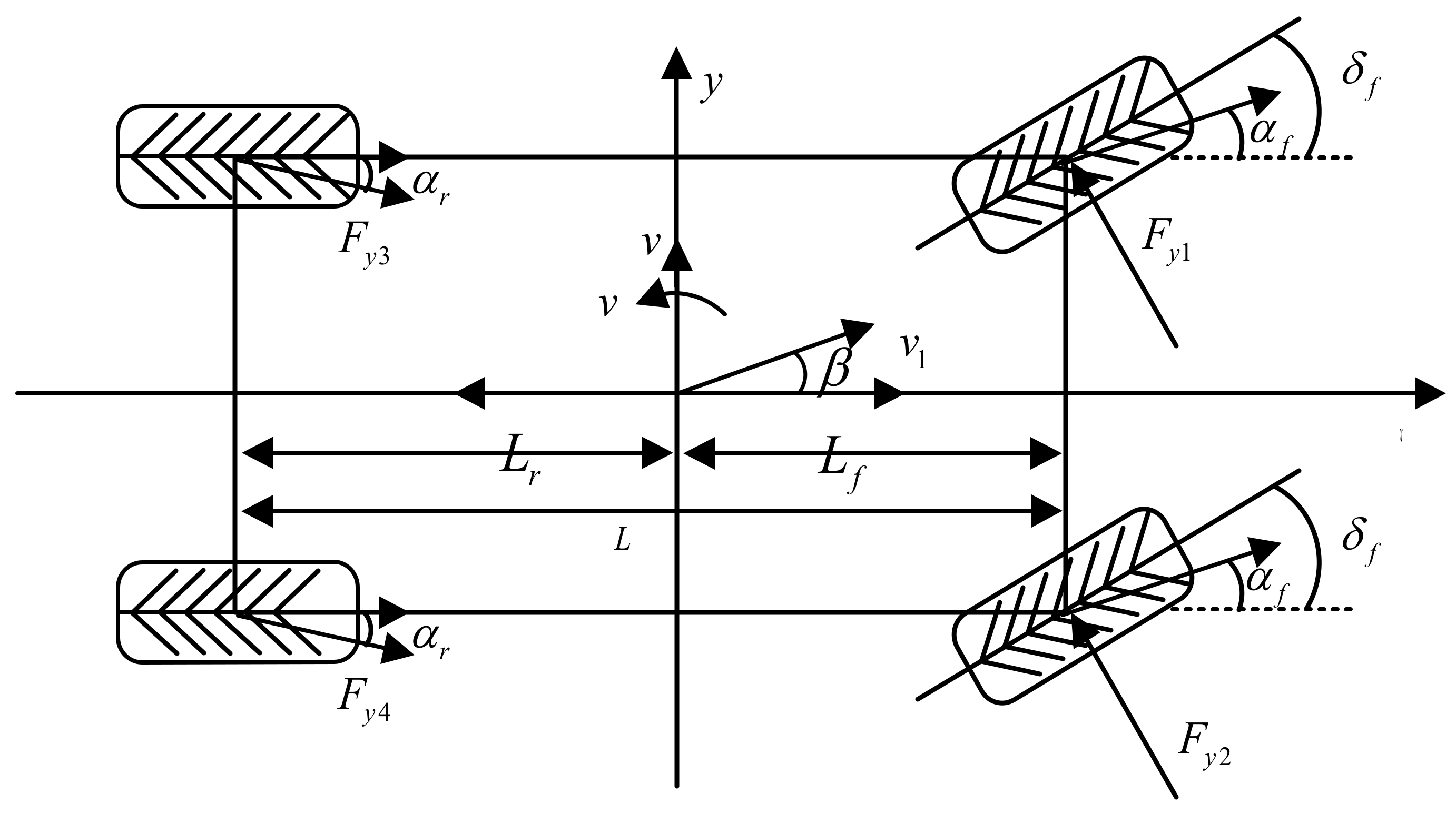
3.1. EV Dynamics Modeling

To analyze the entire EV steering steadiness regulation of a FWID-EV, it is first necessary to establish a dynamics pattern of the EV and to analyze the motion of the EV during driving [21]. As there are many influencing factors related to the EV in the driving process, the EV dynamics has non-linear characteristics, so for the sake of analyzing the steering regulation of the EV, the study simplifies the modeling of the power system and steering regulation system of the EV, ignoring the influence of road impact, drive shaft oscillation and torsional vibration, and vertical tire motion; and simplifies the EV suspension shadow. The EV plane dynamics pattern is displayed in Figure 1.
Let the overall weight of the electric car be F v 2 , the longitudinal and transverse velocities of the car be v x and v y , the lateral eccentricity of the car’s center of mass be β , and the angular velocity of the transverse pendulum be γ . The longitudinal and transverse forces on the front left wheel are F x 1 and F v 1 , respectively; the front right wheel is F x 2 and F v 2 , respectively; the rear left wheel is F x 3 and F v 3 , respectively; the rear right wheel is F x 4 and F v 4 , respectively; and the angle of rotation of the front wheel is δ f . The longitudinal equation of motion in the x-axis and the transverse equation of motion in the y-axis are displayed in Equation (1).
m v ˙ x v y γ = F x 1 + F x 2 cos δ f + F x 3 + F x 4 F y 1 + F y 2 sin δ f m v ˙ y v x γ = F x 1 + F x 2 sin δ f + F y 3 + F y 4 + F y 1 + F y 2 cos δ f
The equation of motion of the transverse pendulum of a car around the center of mass is displayed in Equation (2).
I z γ ˙ = l f F y 1 + F y 2 cos δ f l r F y 3 + F y 4 + 1 2 F y 1 F y 2 sin δ f + M x
In Equation (2), I z indicates the inertia of the car around the z-axis, l f and l r indicate the distance between the center of gravity of the car and its front and rear axles, respectively, l indicates the distance between the front and rear axles of the car, and M x indicates the swaying moment. The kinetic equations of the car are displayed in Equation (3).
J ω ω ˙ = T d r F x i + T e
In Equation (3), J ω indicates the rotational moment of inertia of the car wheel, ω indicates the angular velocity of the wheel, and T d and T e are the driving moment and the disturbance dipole moment of the car wheel, respectively; r is the radial acceleration. For the sake of obtaining the ideal angular velocity of the car, the electric car pattern is transformed into a two-degrees-of-freedom pattern, and the dynamics equations are displayed in Equation (4).
m v x β ˙ = F y f + F y r m v x γ I z γ ˙ = l f F y f l r F y r F y f = K f α f F y r = K r α r
In Equation (4), F y f and F y r are the lateral wheel forces, K f and K r indicate the lateral deflection stiffnesses of the front and rear wheels, respectively, α f is the front wheel lateral deflection angle, and α r is the rear wheel lateral deflection angle of the EV.
The tires of an EV are crucial in the transverse motion of the car, and they are the direct connection between the car and the road, so the study uses a magic tire pattern to pattern the tires of an EV, and derives the dynamics equation for the tires via numerical fitting [22]. The magic tire pattern function is displayed in Equation (5).
F = D sin C arctan B α E B α arctan B α
In Equation (5), F indicates the lateral or longitudinal force of the tire, C indicates the tire curve factor, α is the lateral deflection angle of the tire; D , B , and E are dependent on the vertical load and camber angle.
The motor of an EV, as a torque actuator, is directly related to the dynamics regulation of the EV. EV mainly use permanent magnet brushless direct current (DC) motors, which have obvious advantages in terms of torque and dynamic performance [23]. The equation of state of a permanent magnet brushless DC motor is displayed in Equation (6).
d i a t d t = U a t L a R a L a × d i a t d t + E a d w d t = K m J × i a t K f J × w
In Equation (6), i a and U a are the current and input voltage, respectively, R a is the stator winding resistance, L a is the self-inductance value of the connected winding resistance, and w is the angular speed of the motor; d stands for differential.

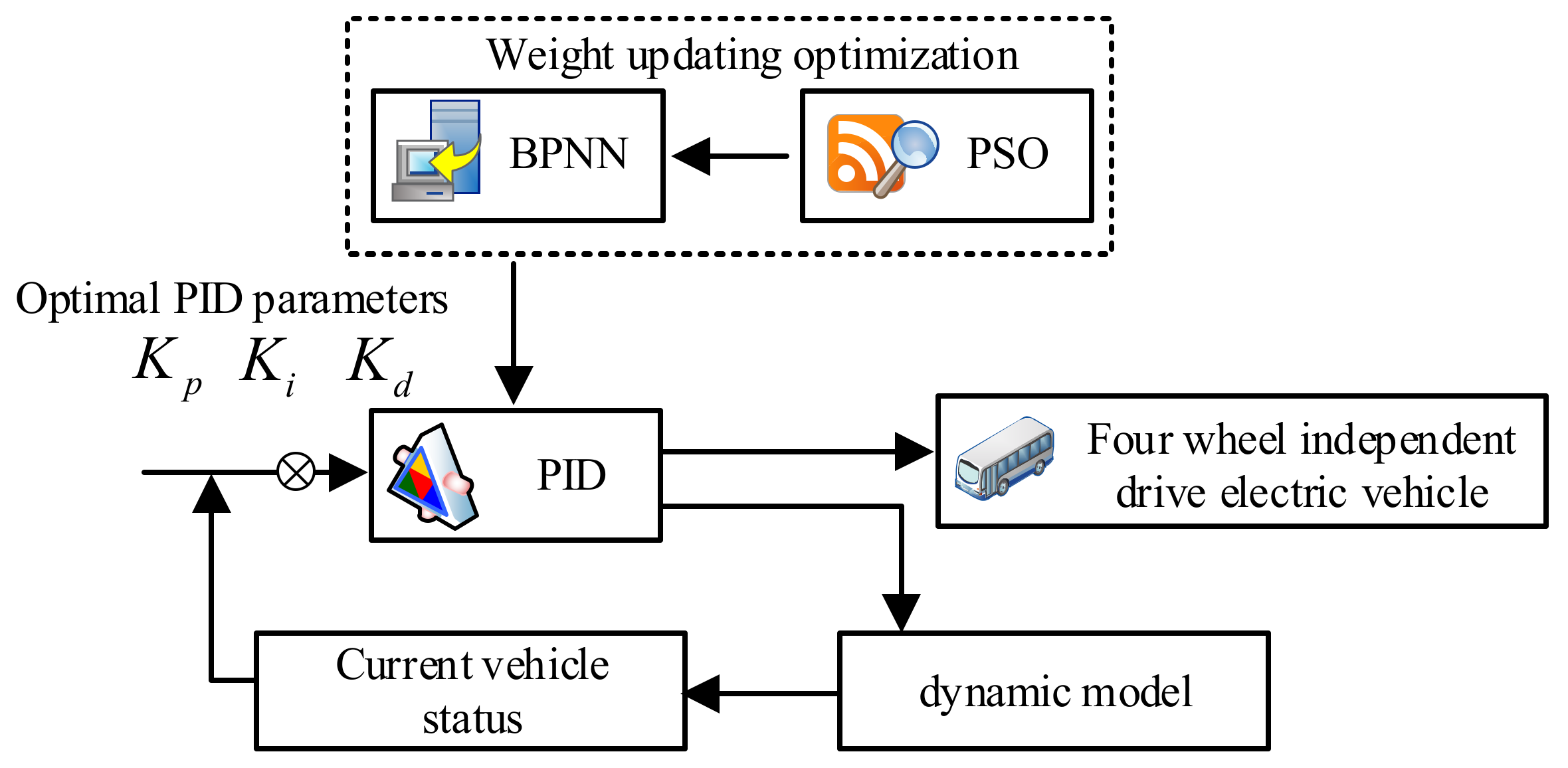
3.2. Design of a Cross-Swing Torque Regulator Based on Improved Neural Network PID

FWID-EV can independently adjust the drive regulation of its four motors to improve the steering regulation, steadiness performance, and safety of the EV. Commonly used EV steering regulation methods include fuzzy PID regulation and sliding mode regulation. Sliding mode regulation approximates to the reference space by spatially dividing the state of the regulation variables. Sliding mode regulation has advantages over non-linear systems, and the response time is faster [24]. However, sliding mode regulation is extremely susceptible to jitter and vibration problems, which affects the immunity of the regulation system and stabilizes the regulation effect. Fuzzy PID regulation can effectively solve nonlinear problems in steadiness regulation, but the complexity of PID regulation is high, and its subordinate degree function also directly affects the final steadiness regulation effect [25,26]. Therefore, the study uses the adaptive and non-linear application advantages of PID regulation, combined with BPNN, and it is further optimized using a Particle Swarm Optimization (PSO) algorithm to build an EV steering steadiness regulator based on an improved neural network PID regulation. The operating flow of the neural network PID regulator is displayed in Figure 2. Combining the search advantages of BPNN and PSO, the PID regulator is optimized and the PID regulator is used to directly regulate the cross-swing angular velocity and the wheel in a closed loop to find the optimal value of PID under the tracking parameter error, and to regulate the error between the ideal cross-swing angular velocity and maintain the actual velocity to a minimum.
A neural network PID algorithm is used to construct a car transverse moment regulator, with the PID regulation law displayed in Equation (7).
u t = K p e t + T i 0 t e t + T d d e t d t
In Equation (7), K p indicates the scaling parameter. The BPNN is combined with PID regulation to make the actual transverse swing torque of the car approximate to the ideal torque, using the input transverse swing angular velocity of the BPNN as the objective function, and the calculation formula is displayed in Equation (8).
g v i = 1 2 j = 1 3 e j 2 n
In Equation (8), g v i indicates the total regulation error. Additionally, the weights of the BPNN are adaptively corrected so that the step size in the weight correction is adaptively changed. The parameter, the weight update formula, is introduced in the weight correction, as displayed in Equation (9).
Δ w n + 1 = η n + 1 1 β e n w m i n + β Δ w n
Additionally, the PSO is used to optimize and update the weights of the BPNN using the global optimization-seeking feature of the PSO, to solve the limitation of the slow convergence speed of the BPNN. The particle position and speed iteration rules of the PSO are displayed in Equation (10).
v i d = ω v i d + c 1 r a n d 1 d p B e s t i x i d + c 2 r a n d 2 d n B e s t x i d x i d = x i d + v i d
In Equation (10), ω is the inertia weight, c 1 and c 2 indicate the acceleration factors, r a n d 1 d and r a n d 2 d are randomly generated constant weights, r a n d 1 d 0 , 1 , r a n d 2 d 0 , 1 , and n B e s t indicate the final optimal positions of each particle, and p B e s t i indicates the optimal position of the individual i . Let the global optimal weight be E p s o , and take a positive number ε , which is infinitely close to 0. When the condition E X p s o E X < ε is satisfied, the search for the optimal neural network is terminated, and the initial weights w i and w o are obtained. The final optimal PID parameters K p , K i , and K d are obtained using the BPNN operation to regulate the transverse swing moment of the car.
γ d e s = v x R = v x L + K δ f K = m v x 2 l r C r l f C f 2 C f C r L

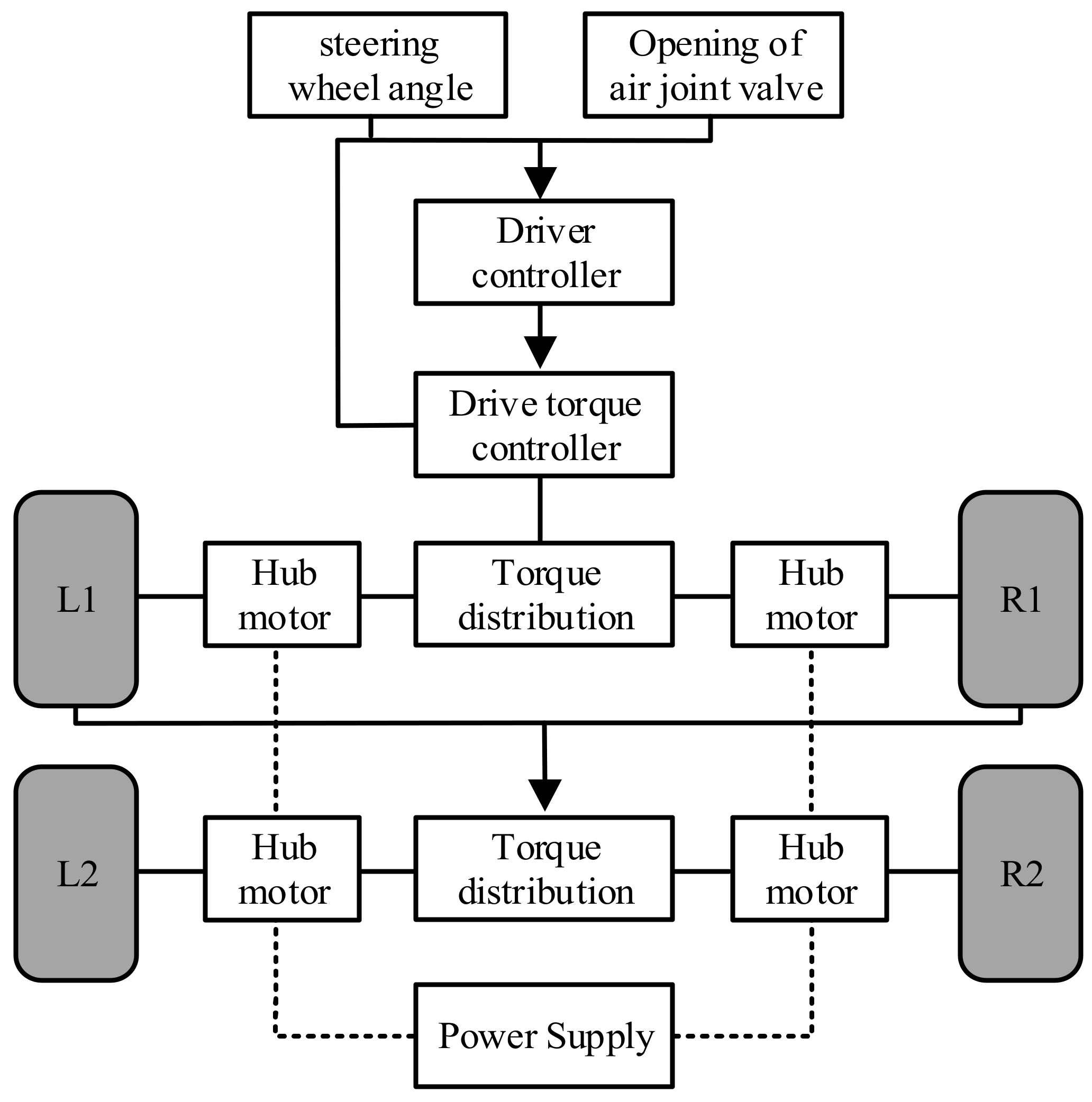
3.3. Torque Distribution for the Steering Condition

The steering regulation of a FWID-EV requires the motor torque of all four wheels to be distributed to achieve the optimum distribution of drive torque, transverse swing torque, and slip rate adjustment torque for each wheel. The wheel torque distribution strategy is displayed in Figure 3. When distributing the wheel torque, the road conditions, motor output conditions, and other influencing factors are taken into account, so that the torque assigned to each wheel is as consistent as possible with the torque required for its actual steering drive.
For the steadiness regulation of car steering, it is required to ensure that the actual steering of the car is as consistent as possible with the driver’s expectations, and so the first term of the regulation objective function is the distribution error; the function is displayed in Equation (12).
J 1 = B u V 2 2
The steadiness of the car steering is the second term of the objective function, through the car wheel utilization rate, to reflect the steadiness of the steering degree. The wheel utilization rate refers to the ground reaction force on the wheels, and eats the ratio of the limit force before the appearance of wheel clamping, the wheel utilization rate function, as displayed in Equation (13).
η i = i = 1 4 F x i 2 + F y i 2 μ F z i 2 2 , i = 1 , 2 , 3 , 4
In Equation (13), μ indicates the road adhesion coefficient, and i = 1 , 2 , 3 , 4 indicate the left front, right front, left rear, and right rear wheels, respectively. Wheel utilization is inversely correlated with steadiness, and therefore, it needs to be reduced as much as possible under controlled circumstances; the sum of the utilization of the four tires of the car is displayed in Equation (14).
{ J 2 = i 1 4 T x i 2 ( r µ F z i ) 2 , i = 1 , 2 , 3 , 4 J 2 = || W u u || 2 2
In Equation (14), W u indicates the weight matrix of the driving moment matrix u . For the sake of reducing B u V , the weighting factor ξ is introduced, and the torque distribution objective function is displayed in Equation (15).
min J = W u u 2 2 + ξ W v B u V 2 2 = A u b 2 2
In Equation (15), W v is the weight matrix of the assignment error,
A = C f + C r m v x l f C f l r C r m v x 2 1 l f C f l r C r I z l f 2 C f l r 2 C r I z v x
Set constraints are made on the regulation function to consider the effects of the car’s slip rate adjustment torque, motor limits, and wheel force saturation limits. For the sake of avoiding the problem of excessive car slip, and to improve car steadiness, the slip rate adjustment torque of the wheels is used as the first constraint, and when the absolute value of the slip rate of a wheel exceeds the maximum threshold, the torque distribution of that wheel is controlled by the slip rate adjustment torque. The torque of the car’s permanent magnet brushless DC motor varies at different speed situations, so the distribution of the car’s torque needs to take full account of the limits of the car’s motor’s power, speed, torque, and other characteristics. Using the car tire force saturation limit as the third of the constraints, the steering regulation of the car is limited by the car drive force, steering force, braking force, and road friction. Under the combined effect of the four constraints, the longitudinal and lateral forces of the tires are synthesized into an approximately elliptical friction circle, requiring the tire forces to be attached to vary within the friction circle. Then, the constraints of the objective function are displayed in Equation (16).
W s u = T max T b r max , r μ F z i 2 F y i 2 T i min T d r max , r μ F z i 2 F y i 2
In Equation (16), T b r max and T d r max indicate the maximum and minimum braking forces that can be given by the motor, respectively.
The effective set method is used to solve the problem, and the effective set is approximated by constructing a geometric sequence. The initial point u 0 is selected within the constraint, the set of effective constraint indicators for u 0 is set to W , and u k is searched along the direction of d k , then the objective function and the constraint are displayed in Equation (17).
min d i   J = A u k + d i b 2 s . t . W s d i = 0 d i = 0 i W
If u k + d i is a feasible solution, then the solution functions for the steps a k = 1 , u k + 1 = u k + d i , and the Lagrange multiplier μ λ are displayed in Equation (18).
A T A u b = B T C 0 T μ λ
When the multiplier, then λ 0 u k + 1 , is the optimal solution, when λ < 0 , then the condition corresponding to the smallest λ is removed from the set of constraint indicators, and a new iteration of u k is performed. If u k + d i is not a feasible solution, the maximum step size a k for solving the feasible solution is corrected for the sequence of valid sets, and the step size calculation function is displayed in Equation (19).
a k = max a k 0 , 1 : u min u k + a k d i u max
Make u k + 1 = u k + a k d i , add the found iteration point and its corresponding constraint to the working set, and proceed to the next iteration update until the best solution in the feasible domain is found.

4. Analysis of the Steering Steadiness Regulation Effect of EV

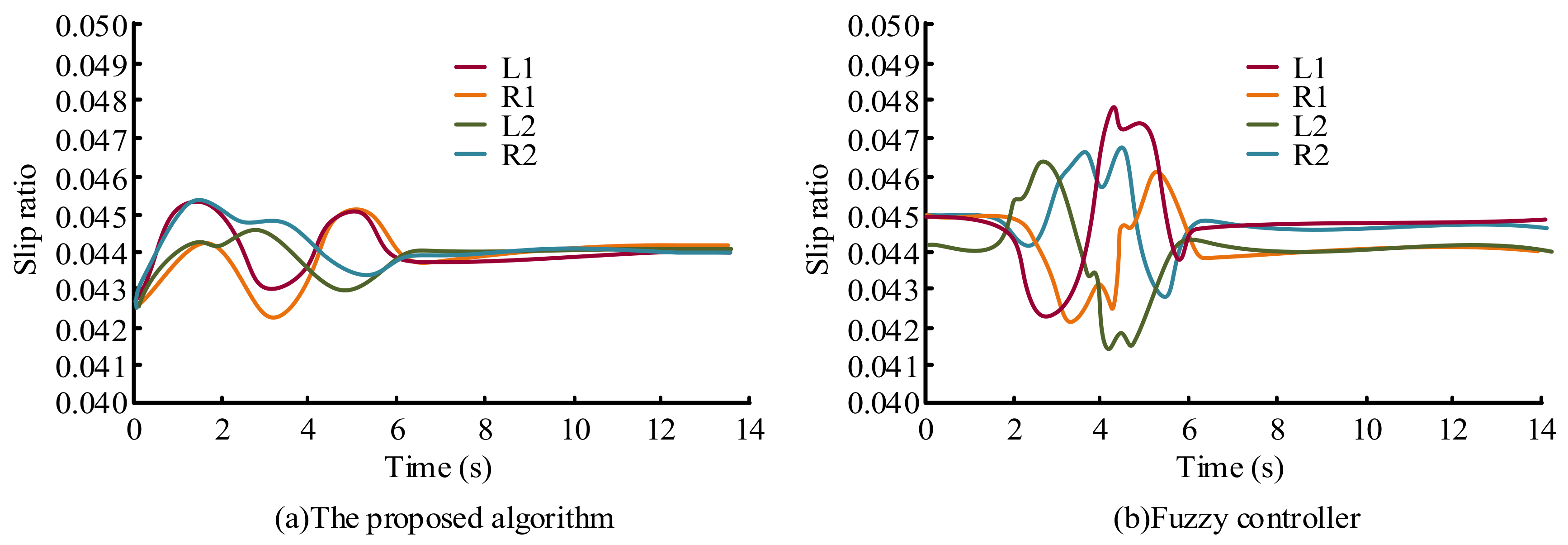
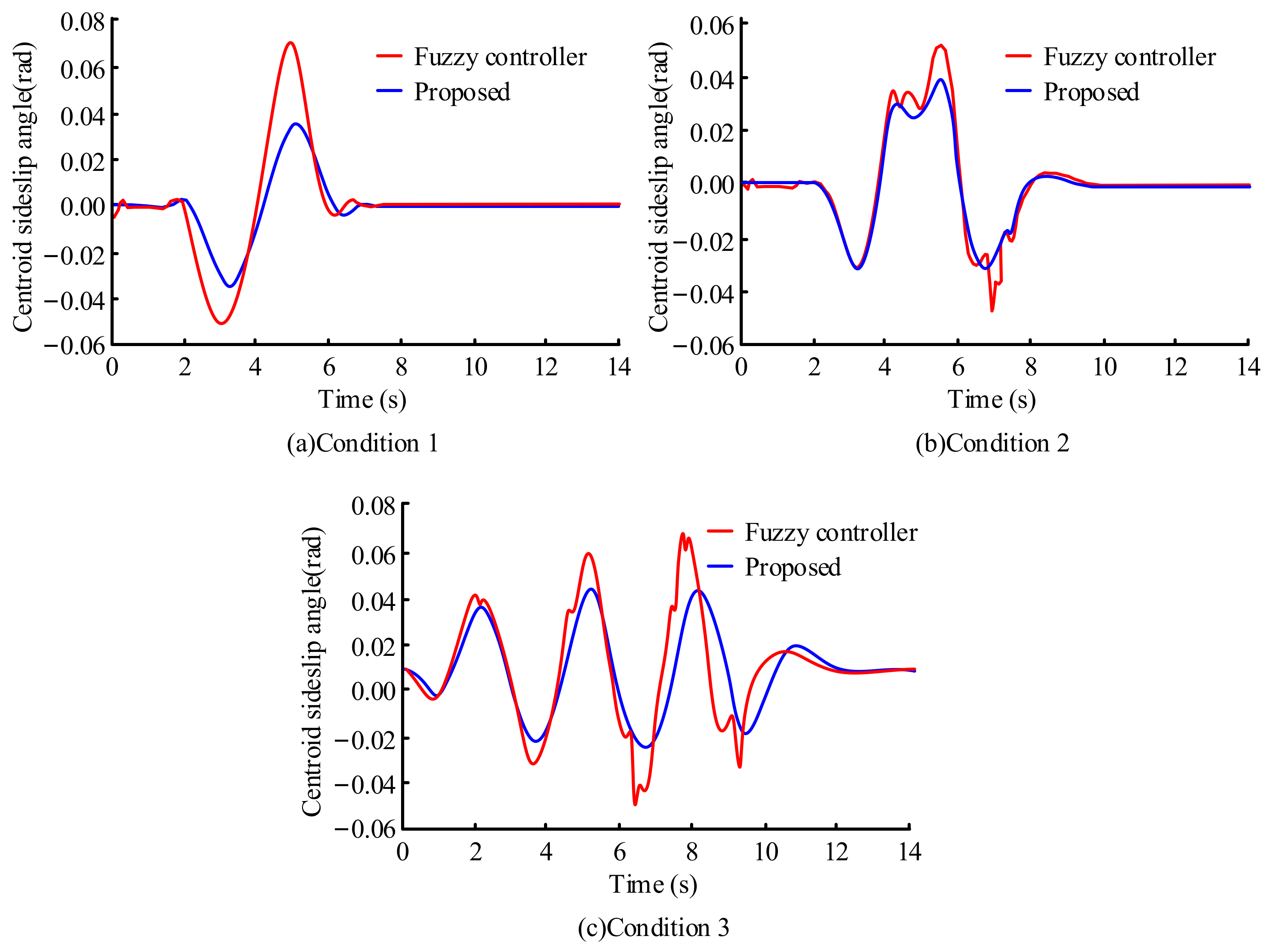
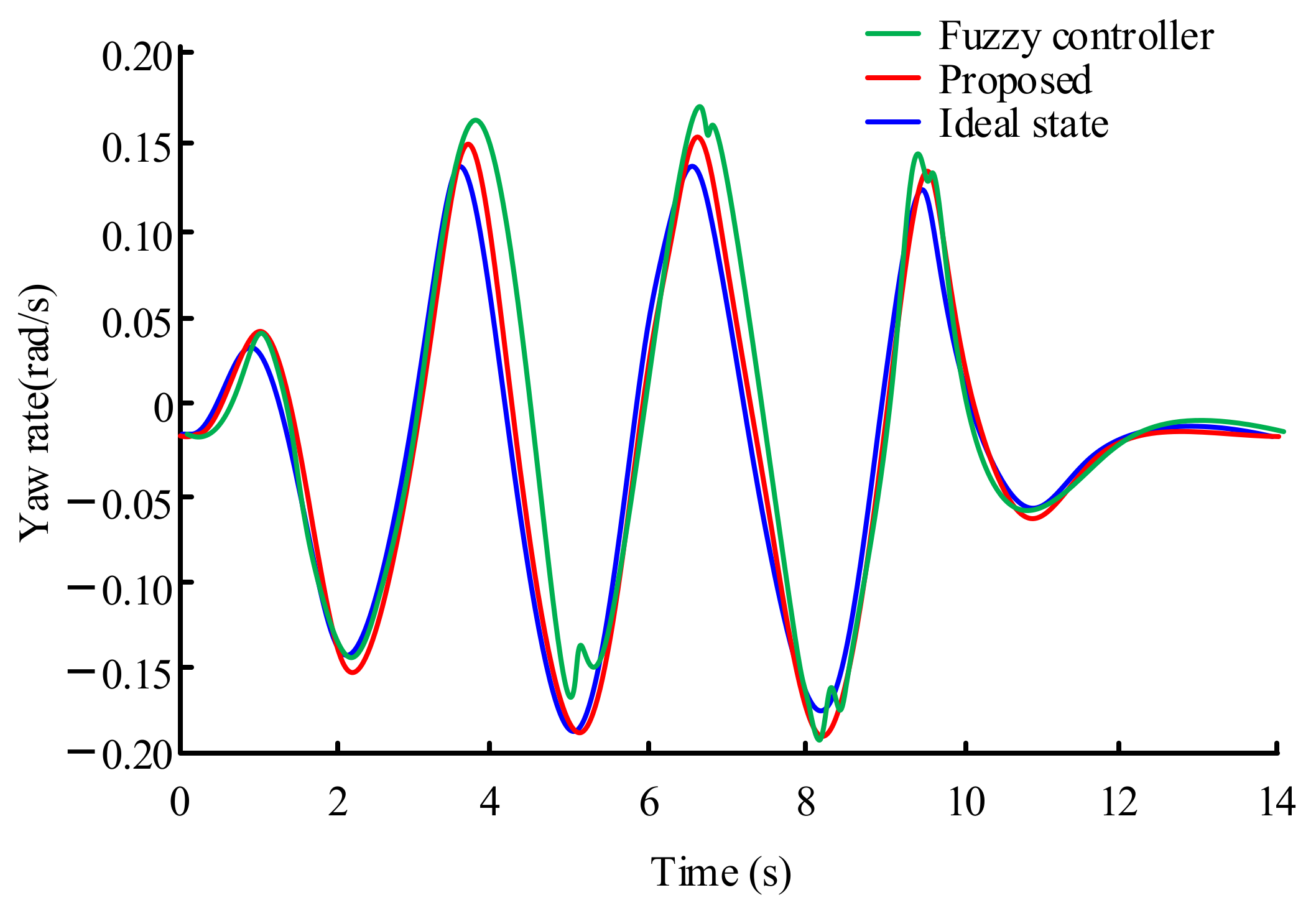
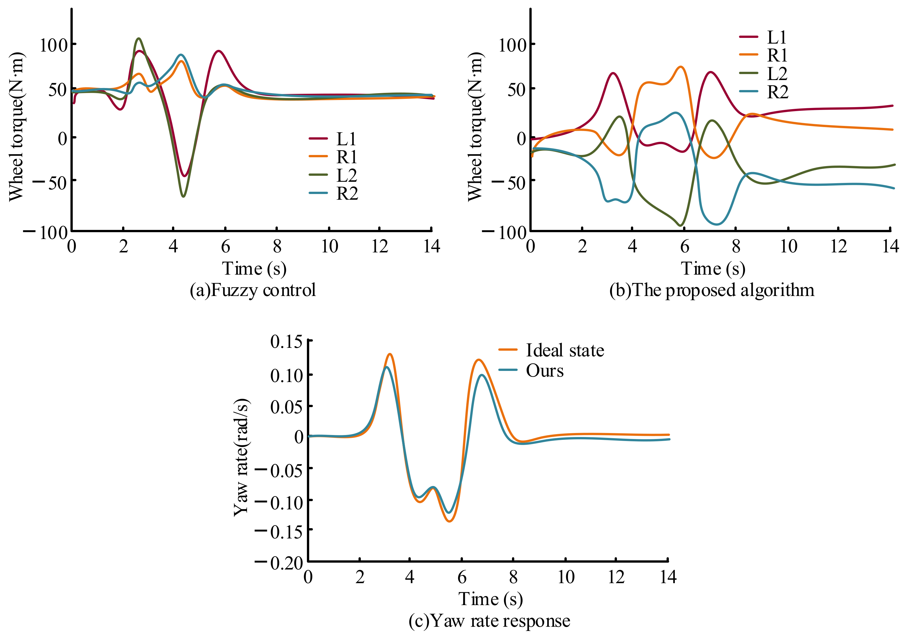
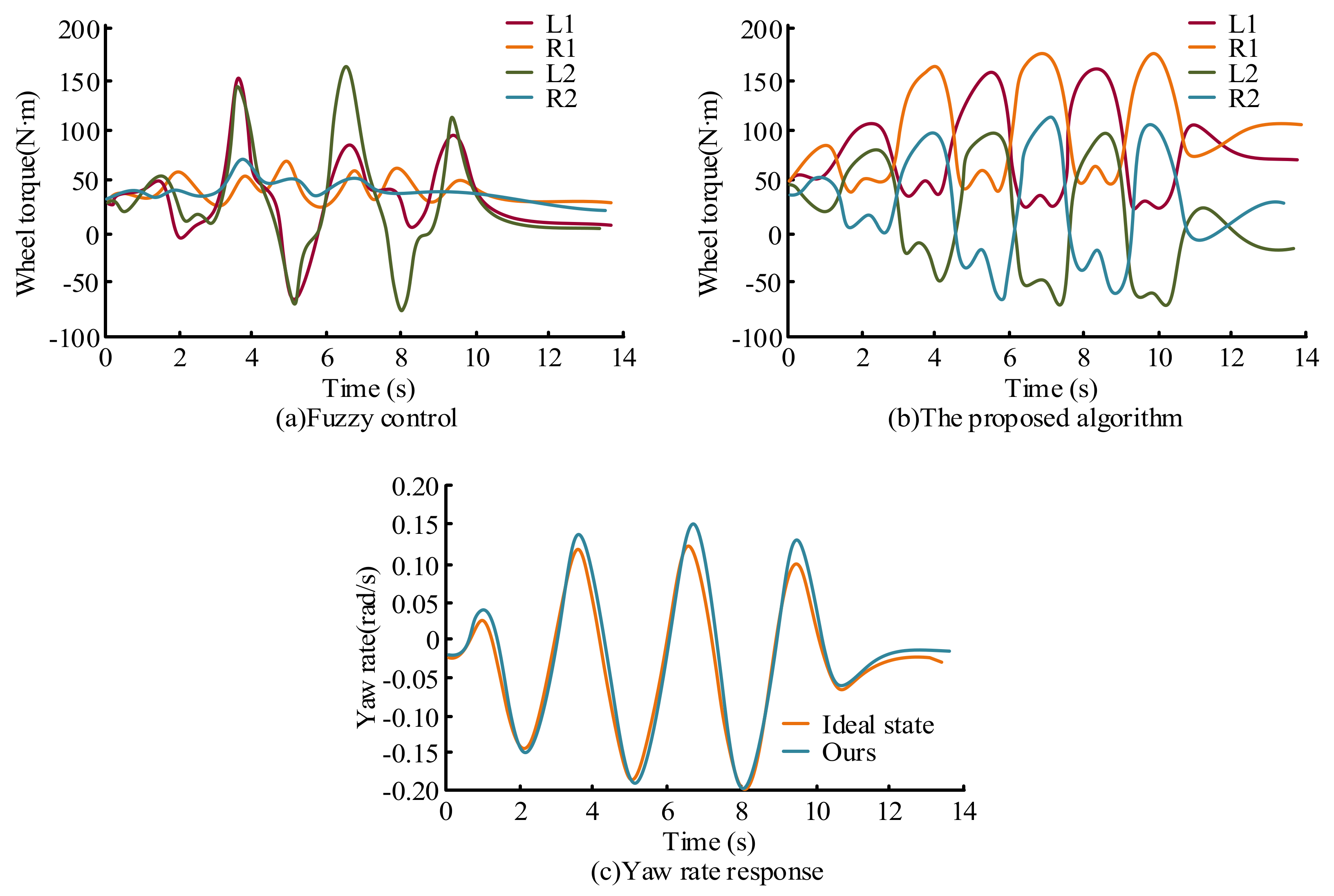
4.1. Analysis of Steering Steadiness Regulation Effects

For the proposed stability control algorithm, simulation experiments are used to verify its effectiveness. Closed loop simulation experiments are conducted using the simulation software Carsim, and the driver preview model in Carsim is used to simulate vehicle steering under different driving conditions. In the simulation experiment, three working conditions are set, namely, a sinusoidal experiment under working condition 1, a double lane shifting experiment under working condition 2, and a serpentine experiment under working condition 3. In the experiment, a vehicle steering wheel angle with a cycle of 4 s is added at 2 s, and the front wheel angle is 10 deg. At the same time, the vehicle speed is increased to 100 km/h, and the actual friction coefficient is set to 0.5, without braking. The experimental setup parameters are shown in Table 1.
Firstly, the corner characteristics under three working conditions are analyzed, and the simulation results of the sideslip angle of the center of mass are shown in Figure 4.
As can be seen in Figure 4, the study compares and analyzes the computational differences between the PID and the fuzzy regulation algorithm under improved neural networks. It is displayed in the results that there is a significant difference in the variation of the lateral deflection angle of the center of mass exhibited by the two steadiness regulation algorithms in different operating modes. It is found that the center-of-mass lateral eccentricity of the put forward algorithm is within 0.04 rad/s in Case 1, which is 47.13% lower than that of the fuzzy regulation algorithm, i.e., a 47.13% increase in controllability. The fuzzy regulation algorithm is able to achieve steadiness and controllability under a variety of operating conditions.
Next, the specific differences between the fuzzy regulation algorithm and the neural network optimized PID algorithm under different operating conditions are analyzed. The differences in the angular speed regulation of the transverse pendulum under serpentine conditions are displayed in Figure 5.
As can be seen in Figure 5, the curve variation trend displayed by the regulation algorithm put forward in the study is highly consistent compared to the ideal state of the transverse pendulum angular velocity, while the fluctuation of the fuzzy regulation algorithm is obvious. The maximum value of the transverse pendulum angular velocity in the ideal state is 0.150 rad/s, while the maximum value of the transverse pendulum angular velocity of the put forward regulation algorithm is 0.156 rad/s, which is not significantly different from the ideal state. Next, the difference in slip rate under the regulation of the two algorithms is analyzed in the sinusoidal operating condition, as displayed in Figure 6.
As can be seen in Figure 6, the four tires of the FWID-EV under the put forward algorithm display little fluctuation during the simulation and the slip rates are small, all within 0.046. In addition, the time required for the two regulation algorithms to reach steadiness also differed, with the put forward regulation algorithm taking 0.02 s and the fuzzy regulation algorithm taking 0.77 s. The above results display that the improved neural network-based PID has a fast and stable performance with low slip rate compared to the fuzzy regulation algorithm. Finally, the performances of the two regulation algorithms were verified in a simulation for the double shift condition, as displayed in Figure 7.
As can be seen in Figure 7, both algorithms were compared for slip rate regulation, and the trend of the curves displays that the put forward regulation algorithm produces less fluctuation than the fuzzy regulation algorithm. With the put forward regulation algorithm, each tire of the FWID-EV exhibited less fluctuation, with the maximum slip rate being controlled to within 0.048, and all four tires starting to stabilize after 8 s. With the fuzzy regulation algorithm, the four tires of the FWID-EV displayed irregular variations in slip rate, indicating that the algorithm gradually lost regulation of the tires, with the maximum slip rate of the tires exceeding 0.049 during the stabilization regulation, and each tire only starting to stabilize regionally after 8.5 s.

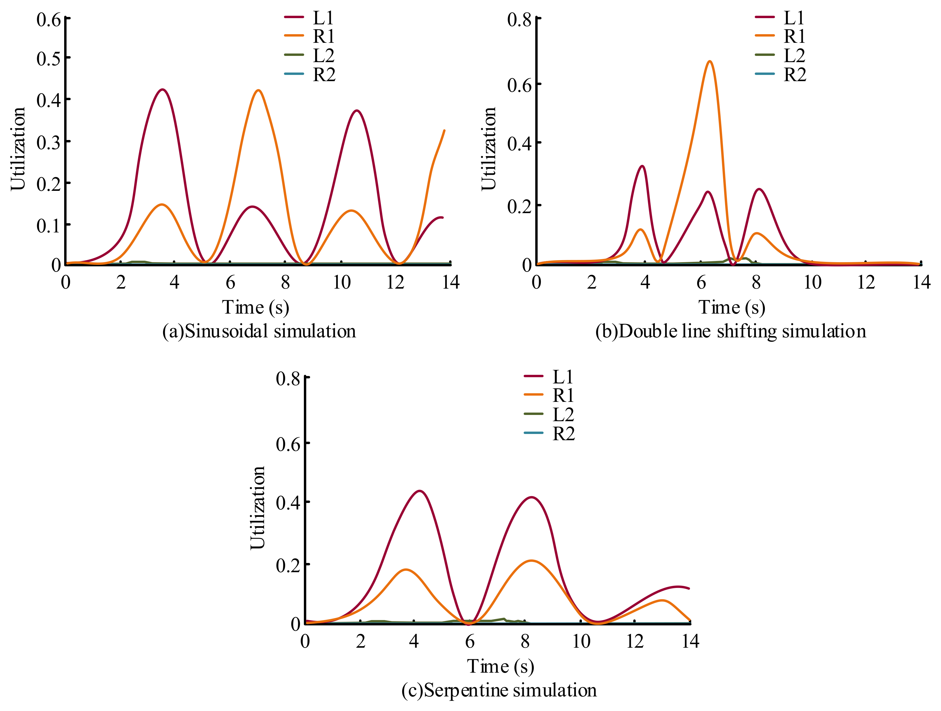
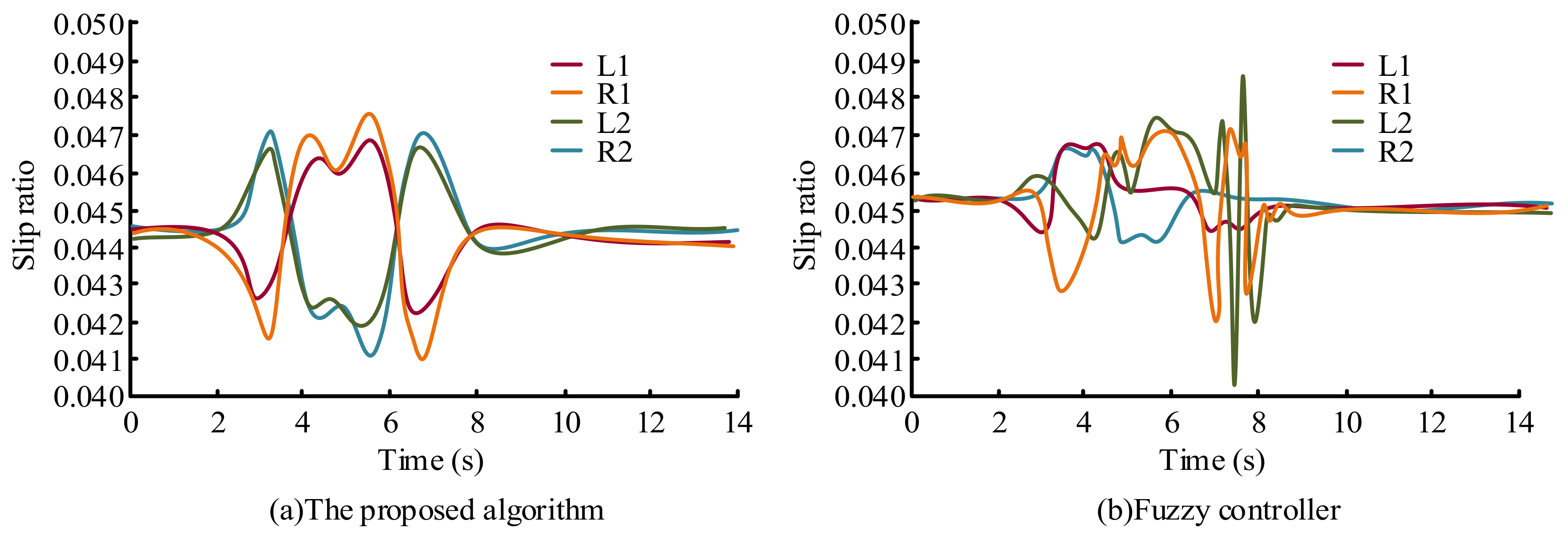
4.2. Analysis of EV Torque Distribution Effects

The effectiveness of the put forward algorithm and its regulation effects under different operating conditions were confirmed through the simulation of the PID with an improved neural network. For the sake of verifying the specific regulation effect of the PID with improved neural network on the FWID-EV, the EV tire utilization under its regulation was analyzed as displayed in Figure 8.
From Figure 8, under the three operating modes, after the PID under the improved neural network for tire drive regulation, the utilization rate of the rear tires of the EV is almost zero, and the maximum utilization rate of the front wheels appears in the double-shifted line operating mode, which is 0.69. Analyzing the magnitude of the tire utilization rate under different operating modes, it can be learnt that under the action of the PID under the improved neural network, the tire utilization rate in all operating modes is at a low level, which meets the requirement of minimizing the tire utilization rate, indicating that the algorithm put forward in the study is feasible. The double-shifted and serpentine conditions are close to realistic road conditions, so it is necessary to carry out specific analyses for both conditions.
From Figure 9a,b, it can be learned from comparing the difference in wheel torque between the fuzzy regulation and the put forward algorithm that the wheel torque can be distributed for a longer period of time with the put forward algorithm, which can reach a maximum value of 100 N-m for the EV compared to the fuzzy regulation. Figure 9c displays the effect of the transverse swing angle speed regulation with the put forward algorithm, and it can be learned that compared to the ideal state, the put forward regulation algorithm is effective in controlling the angular velocity of the transverse swing. The final analysis of the wheel torque and transverse swing speed regulation under serpentine conditions is displayed in Figure 10.
Figure 10a,b displays the variation of wheel torque under the fuzzy control algorithm and the improved neural network optimized PID algorithm. The wheel torque under the two algorithms differs significantly, where the maximum value of wheel torque under the put forward algorithm reaches 179.4 N-m, while the maximum value of wheel torque under the fuzzy regulation is only 162.3 N-m, and it can be found that the regulation of the maximum wheel torque under the put forward algorithm is 179.4 N-m, while the maximum wheel torque under the fuzzy regulation is only 162.3 N-m.

4.3. Actual Application Analysis of the Whole Vehicle

In order to verify the practicability of the improved neural network PID algorithm proposed by the research, the research will compare and analyze the improved neural network PID algorithm with the traditional PID algorithm, the PID algorithm combined with the ant colony optimization (ACO) algorithm, and the fuzzy control algorithm. The stability of the vehicle steering control under the four algorithms will be analyzed through the vehicle actual application experiment, and the effect will be evaluated using the attenuation rate, control phase margin, and control amplitude margin; the evaluation results of the vehicle steering control effects under different control algorithms are shown in Table 2.
It can be seen from Table 2 that the attenuation rate of the improved neural network PID algorithm proposed by the research is 86.9%, which is significantly higher than the other three algorithms, proving that the improved neural network PID algorithm can quickly respond to steering instructions and achieve a fast and stable control. The control phase margin and amplitude margin of the improved neural network PID algorithm are 45.7° and ±39.6 N·m, respectively. The steering control stability is obviously better than the other three algorithms, and the control effect is good.

5. Conclusions

The problem of global energy scarcity has become prominent, and the awareness of environmental protection in various countries has been rising, and so new energy EVs are gradually entering people’s daily lives. For the sake of realizing the steering steadiness regulation of EVs, the study uses the BPNN PID to build an EV steering regulator, and adopts the particle swarm algorithm to optimize and improve the steering steadiness of the EV through the regulation of the transverse swing moment and slip rate of the EV. The results display that the maximum transverse swing angular velocity of the regulation algorithm put forward in the study is 0.156 rad/s, which is not significantly different from the ideal state. The car slip rate is smaller, is controlled within 0.046, and fluctuates less, which is more stable and significantly better than the fuzzy regulation algorithm. The maximum value of torque to the car in the double shift line condition can reach 100 N-m, which can be distributed for a longer period of time, while the maximum value of wheel torque in the serpentine condition reaches 179.4 N-m, which can effectively avoid the danger brought about by steering. The study takes the driving force as the main object of research in the process of the four-wheel torque distribution of the car. In the future, further use can be made of the braking torque, starting from motor braking energy recovery, and continuing to optimize the steering steadiness regulator of EV to improve the safety of car steering regulation.

Author Contributions

Conceptualization, D.S.; data curation, H.J.; formal analysis, K.L.; investigation, D.S.; methodology, H.J.; project administration, K.L.; software, K.L.; validation, K.L.; writing—original draft, D.S.; writing—review & editing, H.J. All authors have read and agreed to the published version of the manuscript.

Funding

This research received no external funding.

Data Availability Statement

The data used to support the findings of this study are available from the corresponding author upon request.

Conflicts of Interest

The authors declare no conflict of interest.

References

  1. Kim, S.; Park, D.J.; Chang, D.E. RAPIDO: A rejuvenating adaptive PID-type optimiser for deep neural networks. Electron. Lett. 2019, 55, 899–901. [Google Scholar] [CrossRef]
  2. Gao, J.L. Research on boiler water supply control system based on at89c55 and fractional order PID algorithm. Procedia Comput. Sci. 2019, 154, 173–180. [Google Scholar] [CrossRef]
  3. Murugesan, R.; Marimuthu, T. Temperature control in plastic extrusion using gaussian offset opposition based whale optimization algorithm. Solid State Technol. 2020, 63, 21411–21426. [Google Scholar]
  4. Xu, W.; Chen, H.; Zhao, H.; Ren, B. Torque optimization control for electric vehicles with four in-wheel motors equipped with regenerative braking system. Mechatronics 2019, 57, 95–108. [Google Scholar] [CrossRef]
  5. Yan, T.; Zheng, K.; Zhao, W.; Song, T. A novel IMC-FOF design for four wheel steering systems of distributed drive electric vehicles. Proc. Inst. Mech. Eng. Part D J. Automob. Eng. 2022, 236, 842–856. [Google Scholar]
  6. Tian, Y.; Cao, X.; Wang, X.; Zhao, Y. Four wheel independent drive electric vehicle lateral stability control strategy. IEEE/CAA J. Autom. Sin. 2019, 7, 1542–1554. [Google Scholar] [CrossRef]
  7. Zhang, L.; Chen, H.; Huang, Y.; Guo, H.; Sun, H.; Ding, H.; Wang, N. Model predictive control for integrated longitudinal and lateral stability of electric vehicles with in-wheel motors. IET Control Theory Appl. 2020, 14, 2741–2751. [Google Scholar] [CrossRef]
  8. Chen, T.; Chen, L.; Xu, X.; Cai, Y.; Sun, X. Simultaneous path following and lateral stability control of 4WD-4WS autonomous electric vehicles with actuator saturation. Adv. Eng. Softw. 2019, 128, 46–54. [Google Scholar] [CrossRef]
  9. Hu, J.; Tao, J.; Xiao, F.; Niu, X.; Fu, C. An optimal torque distribution control strategy for four-wheel independent drive electric vehicles considering energy economy. IEEE Access 2019, 7, 141826–141837. [Google Scholar] [CrossRef]
  10. Wang, C.; Bo, H.; Zhao, W. Yaw and lateral stability control for four-wheel-independent steering and four-wheel-independent driving electric vehicle. Proc. Inst. Mech. Eng. Part D J. Automob. Eng. 2020, 234, 409–422. [Google Scholar] [CrossRef]
  11. Jie, Y.I.; Liu, Z.W.; Zeng, W.Q. Isothermal extrusion speed curve design for porthole die of hollow aluminium profile based on PID algorithm and finite element simulations. Trans. Nonferrous Met. Soc. China 2021, 31, 1939–1950. [Google Scholar]
  12. Asl, R.M.; Mahdoudi, A.; Pourabdollah, E.; Klančar, G. Combined PID and LQR regulator using optimized fuzzy rules. Soft Comput. 2019, 23, 5143–5155. [Google Scholar]
  13. George, T.; Ganesan, V. An effective technique for tuning the time delay system with PID regulator-ant lion optimizer algorithm with ANN technique. Int. J. Comadem 2020, 23, 39–48. [Google Scholar]
  14. Jinbao, C.; Xiong, C.; Jingliang, Z.; Kun, H. Adaptive fuzzy immune PID control for gas generator pressure based on artificial bee colony algorithm optimization. J. Propuls. Technol. 2019, 40, 441–448. [Google Scholar]
  15. Chen, G.; Li, Z.; Zhang, Z.; Li, S. An improved ACO algorithm optimized fuzzy PID regulator for load frequency control in multi area interconnected power systems. IEEE Access 2020, 8, 6429–6447. [Google Scholar] [CrossRef]
  16. Li, Y.; Huang, X.; Liu, D.; Wang, M.; Xu, J. Hybrid energy storage system and energy distribution strategy for four-wheel independent-drive electric vehicles. J. Clean. Prod. 2019, 220, 756–770. [Google Scholar] [CrossRef]
  17. Ding, X.; Wang, Z.; Zhang, L.; Wang, C. Longitudinal vehicle speed estimation for four-wheel-independently-actuated electric vehicles based on multi-sensor fusion. IEEE Trans. Veh. Technol. 2020, 69, 12797–12806. [Google Scholar] [CrossRef]
  18. Peng, H.; Wang, W.; Xiang, C.; Li, L.; Wang, X. Torque coordinated control of four in-wheel motor independent-drive vehicles with consideration of the safety and economy. IEEE Trans. Veh. Technol. 2019, 68, 9604–9618. [Google Scholar] [CrossRef]
  19. Song, Y.; Shu, H.; Chen, X.; Luo, S. Direct-yaw-moment control of four-wheel-drive electrical vehicles based on lateral tyre-road forces and sideslip angle observer. IET Intell. Transp. Syst. 2019, 13, 303–312. [Google Scholar] [CrossRef]
  20. Guo, L.; Ge, P.; Sun, D. Torque distribution algorithm for steadiness control of electric vehicle driven by four in-wheel motors under emergency conditions. IEEE Access 2019, 7, 104737–104748. [Google Scholar] [CrossRef]
  21. Li, C.; Xie, Y.F.; Wang, G.; Liu, S.Q.; Kuang, B.; Jing, H. Experimental study of electric vehicle yaw rate tracking control based on differential steering. J. Adv. Transp. 2021, 2021, 6668091. [Google Scholar] [CrossRef]
  22. Sun, H.; Wang, H.; Zhao, X. Line braking torque allocation scheme for minimal braking loss of four-wheel-drive electric vehicles. IEEE Trans. Veh. Technol. 2019, 68, 180–192. [Google Scholar] [CrossRef]
  23. Le, V.Q.; Cuong, B.V.; Liem, N.V.; Long, L.X.; Thanh Dung, P.T. Effect of in-wheel motor suspension system on electric vehicle ride comfort. Vibroeng. Procedia 2019, 29, 148–152. [Google Scholar]
  24. Wang, Y.; Fu, P. Integration performance statistics of green suppliers based on fuzzy mathematics and BP neural network. J. Intell. Fuzzy Syst. 2021, 40, 2083–2094. [Google Scholar] [CrossRef]
  25. Xi, H.; Li, Z.; Han, J.; Shen, D.; Li, N.; Long, Y.; Chen, Z.; Xu, L.; Zhang, X.; Niu, D.; et al. Evaluating the capability of municipal solid waste separation in China based on AHP-EWM and BP neural network. Waste Manag. 2022, 139, 208–216. [Google Scholar] [CrossRef]
  26. Chen, Z.; Yuan, X.; Yuan, Y.; Lei, X.; Zhang, B. Parameter estimation of fuzzy sliding mode regulator for hydraulic turbine regulating system based on HICA algorithm. Renew. Energy 2019, 133, 551–565. [Google Scholar] [CrossRef]
Figure 1. Planar dynamic pattern of EV.
Processes 10 02106 g001
Figure 2. Operation flow of neural network PID controller.
Processes 10 02106 g002
Figure 3. Torque distribution strategy.
Processes 10 02106 g003
Figure 4. Simulation results of centroid sideslip angle.
Processes 10 02106 g004
Figure 5. Difference in yaw rate regulation under serpentine condition.
Processes 10 02106 g005
Figure 6. Difference of slip ratio under regulation of two algorithms.
Processes 10 02106 g006
Figure 7. Performance of two regulation algorithms under double line shifting condition.
Processes 10 02106 g007
Figure 8. EV tire utilization under regulation.
Processes 10 02106 g008
Figure 9. Variation of wheel torque and yaw rate under double line shifting condition.
Processes 10 02106 g009
Figure 10. Regulation effect of wheel torque and yaw rate under serpentine condition.
Processes 10 02106 g010
Table 1. Experiment setting parameters.
ParameterValue
Input vector length3
Output vector length3
Number of input layers3
Number of neurons in hidden layer5
Hidden layer vector field5
Accelerated pace1.5
Inertia threshold0.8
Maximum number of updates50
Table 2. Evaluation results of vehicle steering control effect under different control algorithms.
AlgorithmAttenuation RatePhase MarginGain Margin
Traditional PID32.7%−102.9°±89.4 N·m
ACO-PID63.8%65.4°±53.1 N·m
Fuzzy control56.3%78.3°±60.7 N·m
Proposed algorithm86.9%45.7°±39.6 N·m
Publisher’s Note: MDPI stays neutral with regard to jurisdictional claims in published maps and institutional affiliations.

