Article

Robust Intelligent Tracking Control Technique for Single-Phase SPWM Inverters

1
Department of Electrical Engineering, I-Shou University, No.1, Sec. 1, Syuecheng Rd., Dashu District, Kaohsiung City 84001, Taiwan
2
Department of International Media and Entertainment Management, I-Shou University, No.1, Sec. 1, Syuecheng Rd., Dashu District, Kaohsiung City 84001, Taiwan
*
Author to whom correspondence should be addressed.
Processes 2023, 11(1), 13; https://doi.org/10.3390/pr11010013
Submission received: 10 October 2022 / Revised: 5 December 2022 / Accepted: 19 December 2022 / Published: 21 December 2022
(This article belongs to the Special Issue Application of Power Electronics Technologies in Power System)

Abstract

:
This paper presents a robust intelligent tracking-control technique which is subsequently applied to single-phase SPWM inverters. The proposed technique mixes advanced sliding mode control (ASMC) with grey-Markov model (GMM). The advanced sliding mode control allows the system state to converge quickly to the origin in a limited amount of time. Unfortunately, a chattering problem frequently occurs when the inverter suffers drastically from highly nonlinear or internal parameters changes. The large power losses and high harmonic distortion emerge in the inverter output. The role that the grey-Markov model plays is to reduce the chattering of the ASMC during system uncertainty overestimation, or to reduce the steady-state error caused by underestimation of system uncertainty. In conjunction with the GMM and the ASMC, fast transient response, low distortion of the sinusoidal output-voltage and reduced chattering can be obtained. Simulation results of the proposed single-phase SPWM inverter are carried out in MATLAB/Simulink. The experimental results have been validated through digital signal processors, enabling the single-phase SPWM inverter output to effectively improve the transient tracking speed and steady-state performance.

1. Introduction

There is a growing interest in high quality and high performance single-phase SPWM inverters, which are also widely used to provide alternating current (AC) sinusoidal output voltages with low harmonic distortion, fast dynamic response and zero steady-state error [1,2,3,4]. These performance requirements can be established by closed-loop control schemes. In previous research, a number of techniques for controlling inverters have been published, for instance, the linear quadratic regulator (LQR) scheme, resonant approach, proportional integral (PI) controller, as well as H-infinity control. An LQR-based robust voltage controller can be applied to inverter design during system black start to achieve good stability. However, it is necessary to make a compromise between transient and steady-state response [5]. The photovoltaic micro-inverter using a power control scheme has been proposed. The developed scheme uses the resonant concept to achieve maximum power point tracking as well as to control total system active power. The inverter can produce a good performance, but the implementation circuit is a bit complicated [6]. The integration of a proportional–integral state-feedback controller and three-dimensional space vector modulation has been proposed to design grid inverters. This control method allows for quicker as well as more precise feedback of dynamic behavior, nevertheless the steady-state performance can be strengthened [7]. A control strategy with proportional resonance and proportional integral for single phase quasi-Z-source inverters is suggested. Such a methodology can effectively govern the control variables on both the direct current (DC) and AC sides, except for the sophisticated and time-consuming mathematical modeling [8]. A kind of new H-infinity control explores the stability problem of grid-connected inverters exposed to grid impedance fluctuations. Although a good dynamic response can be obtained, the steady-state performance still requires improvement [9]. Sliding mode control is known to be simple in structure, easy to design and insensitive to changes in internal parameters and external load disturbances [10,11,12,13]. In other words, the system behavior is robust to disturbances when sliding motion occurs. A great deal of published literature on sliding mode control demonstrates the effectiveness of its use in SPWM inverters [14,15,16,17,18,19,20]. However, the system state of conventional sliding mode control has a theoretically infinite, i.e., the time to convergence to the origin is not finite, and it suffers from frequent chattering problems. Advanced sliding mode control has robust and insensitive properties, a clear architectural design philosophy and good control effects [21,22,23,24,25,26,27,28]. It allows the system to retain its reliability as well as stability in the face of parametric uncertainties. More interestingly, the advanced sliding mode control permits a limited system state retraction time, i.e., when the plant is disturbed by uncertainty, the system movement can attain a sliding region for a limited time, and then generate a sliding motion leading to a rapid retraction to the origin. Even though the advanced sliding mode control described above has further improved the dynamic response of the system, the chatter may still persist. The chatter poses a challenge during implementation as it means excessive energy dissipation as well as high harmonic distortion voltage in the SPWM inverter output. In some instances, it may also provoke unmodelled high-frequency controlled field dynamics, which could lead to system instability. Despite the fact that they are capable of solving the problem of the chattering as well as strengthening transient response in the event of uncertainty, the mathematical complexity of these techniques is considerable and the calculations require a lot of time [29,30,31,32]. The grey model is distinguished by its computational simplicity, low information needs and the ability to model an arbitrary discrete series with high precision for short-term forecasts [33,34,35]. However, it provides a poorer approximation in long-term forecasting and highly volatile series. The Markov chain can remedy the deficiencies of the grey model and achieve more accurate predictions [36,37,38]. Hence, in the case of overestimation of system uncertainty, a simple mathematical and efficient grey-Markov model is available to mitigate chattering or to decrease the steady-state error caused by underestimation of system uncertainty. One may note that using a closed-loop controlled single-phase SPWM inverter in conjunction with ASMC and GMM results in a high quality AC output voltage. The proposed technique has remarkable contributions in terms of simplicity, ease of programming, quick convergence and elimination of chattering and steady-state errors. This causes a higher level of exact tracking control as well as a more stable and robust operation of the inverter. Both simulation and experimental results have been presented for verification purposes regarding the correctness of the theoretical analysis.

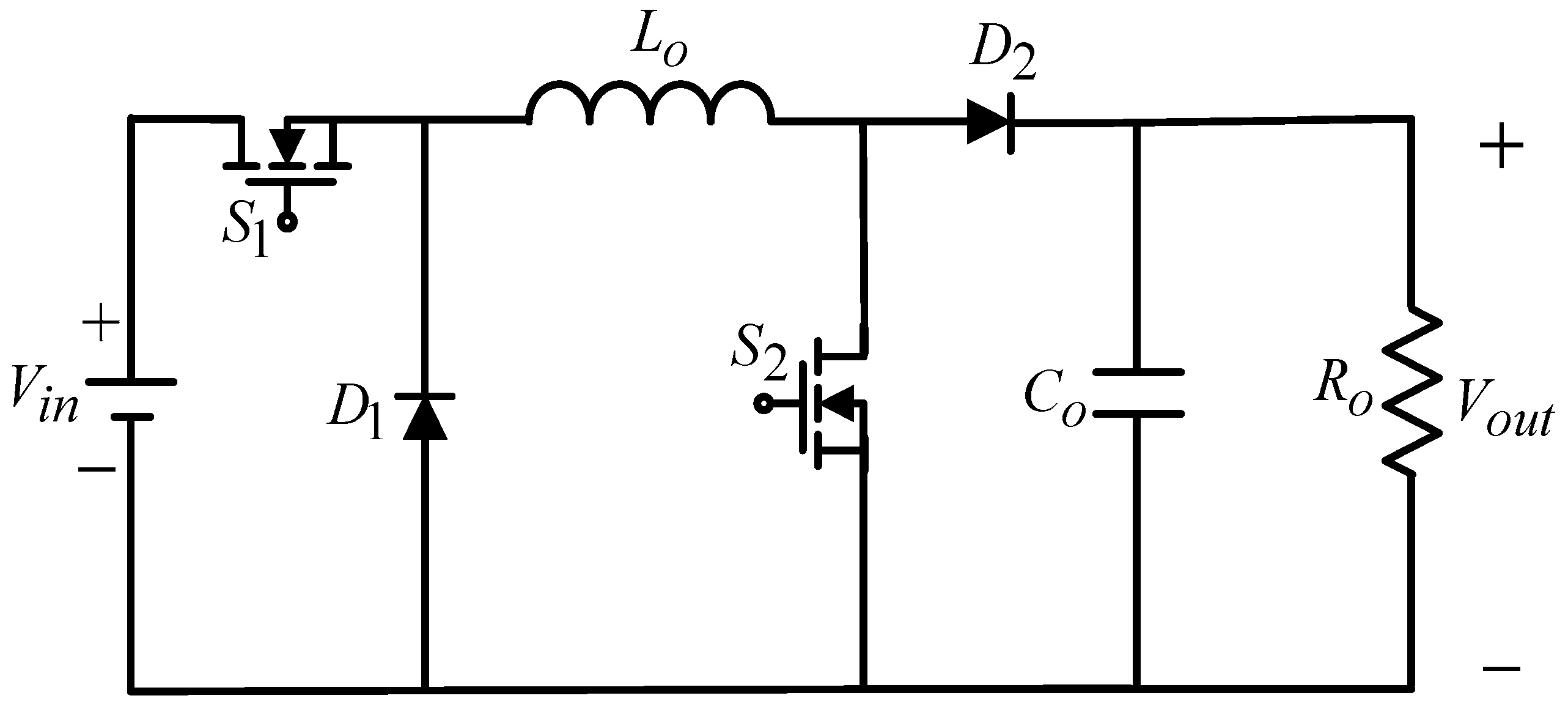
2. Modeling of Single-Phase SPWM Inverter

Figure 1 gives an indication of a block diagram relating to a single-phase SPWM inverter. Both the LC (inductor capacitor) filter as well as the adopted load may be available to serve as a plant in a closed-loop dynamic system. It is allowed to be a resistance type of load, a stepped load and/or a full-wave diode rectifier load. This means that the single-phase inverter forms the circuit’s kernel, chopping the DC input as a sequence of SPWM pulses in response to the modulated signal. The purpose of the LC filter would be to eliminate the high frequency part of the chopped output voltage. Assuming that the switching frequency becomes sufficiently high to disregard the inverter dynamics, then in that case the inverter is modeled with a constant gain, k s p w m . According to the small signal modeling theory of pulse-width-modulated switching power converters as well as the state-space averaging method [39,40,41], the inverter, LC filter and load can be derived as a linear time-invariant model.
Through the use of the proposed technique, the output voltage v o of a single-phase SPWM inverter is enforced to match a sine referenced voltage v r . When e 1 = v o v r and e 2 = e ˙ 1 are defined, it is possible to derive the error dynamic state space equation as follows:
[ e ˙ 1 e ˙ 2 ] = [ 0 1 a 1 a 2 ] [ e 1 e 2 ] + [ 0 b ] u + [ 0 ϕ ]
where a 1 = 1 L C ; a 2 = 1 R C ; b = k s p w m L C ; L = L 1 + L 2 ; k s p w m represents the gain equivalent to the single-phase SPWM inverter as well as ϕ = a 1 v r a 2 v ˙ r v ¨ r stands for systematic uncertainties. While the parameter a 1 has been determined, there is no definition of the parameter a 2 , which depends on the load circumstances. It is, in fact, impossible to forecast the loading situation, but the load variable extent is restricted by the design of the inverter. The parameter a 2 shall therefore be specified in a ¯ 2 δ a 2 < a 2 < a ¯ 2 + δ a 2 , in which the bar on the character symbol signifies the nominative value and the symbol δ is the parameter change.
The control signal would be designed to make e 1 as well as e 2 converge towards zero. For this reason, as GMM is used to decrease the chattering, the ASMC is able to force the convergence of the system tracking error towards zero for a limited period of time, which guarantees the stability with a closed loop as well as yielding a higher performance in terms of AC output-voltage. With the introduction of GMM and ASMC, it will refine the conventional SMC to address the issues of unlimited time convergence and chattering.

3. Design of Control Technique

For the error state Equation (1), a sliding surface is required to ensure a quick time-limited convergence and absence of singularities, which could be formulated as follows:
σ = e 1 + η e 2 β / α
where η > 0 , and both α and β are positively odd restricted to 1 < β / α < 2 . For quick entrance into the sliding surface, a sliding mode reaching law is designed as follows:
σ ˙ = ρ 1 | σ | γ sgn ( σ ) ρ 2 | σ | sinh 1 ( κ σ )
where ρ 1 > 0 ; ρ 2 > 0 ; κ > 0 ; and 0 < γ < 1 .
Depending on (1)–(3), the control law u of the ASMC gives:
u = b 1 [ a 1 e 1 + a 2 e 2 + α β η e 2 β / α + ρ 1 | σ | γ sgn ( σ ) + ρ 2 | σ | sinh 1 ( κ σ ) ]
Proof. 
The following is a candidate definition of the Lyapunov function:
V = 0.5 σ 2
It is possible to obtain the time derivative V by using the tracking trajectory (1) as well as the control law (4) as follows:
V ˙ = σ σ ˙ = σ ( e 1 + η e 2 β / α ) σ [ ρ 1 | σ | γ sgn ( σ ) + ρ 2 | σ | sinh 1 ( κ σ ) ]
One sees from (6) that it is not equal to zero with respect to σ and e 2 , resulting in V ˙ being less than zero. The (4) represents a time-constrained convergence of the system states. Nevertheless, (4) has an sgn function and if the load is a large stepped change/high-level of non-linearity, there will be a chatter problem. The operation of the GMM to address such issues is illustrated below. The GMM is employed to predict output voltage. Based on the five latest output-voltage values, the GMM is derived to forecast the next output voltage state. □
Step 1: It is necessary to assume that the original data sequence χ ( 0 ) (output voltage values) is denoted as follows:
χ ( 0 ) = { χ ( 0 ) ( 1 )   ,   χ ( 0 ) ( 2 ) ,   ,   χ ( 0 ) ( n ) }
where n refers to the amount of data. Typically, a sequence can be built to depict the output-voltage information changes by using fewer (at least four) original data points; if the choice of n is greater than five, then more calculations are required.
Step 2: Consider the following expression for accumulated generating operation (AGO)
χ ( 1 ) ( k ) = m = 1 k χ ( 0 ) ( m )
where k = 1 ,   2 ,   ,   n .
Step 3: By means of a first-order differential grey model through χ ( 1 ) , it is possible to obtain as follows:
d χ ( 1 ) d t + Ψ χ ( 1 ) = Γ
where both Ψ and Γ indicate the model factors required to be decided.
The data sequence to achieve the grey background values is derived by adopting the mean generation operation on χ ( 1 ) as follows:
Ζ ( 1 ) ( k ) = [ χ ( 1 ) ( k 1 ) + χ ( 1 ) ( k ) ] / 2
where k = 1 ,   2 ,   ,   n .
Writing the (10) as a discrete sequence, it can be expressed as follows:
χ ( 0 ) ( k ) + Ψ Ζ ( 1 ) ( k ) = Γ
Using the least square method to find Ψ and Γ , we obtain:
Ξ = [ Ψ Γ ] = ( λ T λ ) 1 λ T υ
where λ = [ [ χ ( 1 ) ( 1 ) + χ ( 1 ) ( 2 ) ] / 2 1 [ χ ( 1 ) ( 2 ) + χ ( 1 ) ( 3 ) ] / 2 1 [ χ ( 1 ) ( n 1 ) + χ ( 1 ) ( n ) ] / 2 1 ] , and   υ = [ χ ( 0 ) ( 2 ) χ ( 0 ) ( 3 ) χ ( 0 ) ( n ) ] .
Putting the values of Ψ and Γ into the (11) gives the following forecast output:
χ ^ ( 1 ) ( k + 1 ) = ( χ ( 0 ) ( 1 ) Γ Ψ ) e Ψ k + Γ Ψ
Step 4: The prediction output can be calculated at ( k + 1 ) with the inverse accumulated generating operation (IAGO):
χ ^ ( 0 ) ( k + 1 ) = ( 1 e Ψ ) [ χ ( 0 ) ( 1 ) Γ Ψ ] e Ψ k
Step 5: Based on the tendency curve χ ^ ( 0 ) ( k ) , the zone is partitioned into a number of strips parallel to the tendency curve. Each zone constitutes one state, i.e., a non-stationary random sequence χ ^ ( 0 ) ( k ) conforming to the characteristics of the Markov chain is divided into n states, any of them being:
Λ i = [ A 1 i , A 2 i ]  
where A 1 i = χ ^ ( 0 ) ( k ) + ς i ; A 2 i = χ ^ ( 0 ) ( k ) + ξ i ; the upper limit ς i and lower limit ξ i of the striped zone are ( χ ( 0 ) ( k ) χ ^ ( 0 ) ( k ) ) u p p e r and ( χ ^ ( 0 ) ( k ) χ ( 0 ) ( k ) ) l o w e r , respectively.
Step 6: The state transfer probability matrix can be calculated as follows:
p i j m = M i j m / M i
where M i j m is the number of original data samples transferred from state Λ i to state Λ j in m steps; M i stands for the number of original data samples of the system at state Λ i .
Step 7: The system is calculated to be at state Λ k which is estimated by:
Χ ^ ( k ) = χ ( 0 ) ( k ) + 0.5 × ( ς i + ξ i )
Therefore, the control method of (4) adds a GMM term ( u g m m ) to remove the chattering as follows:
u g m m ( k ) = { 0 H σ ^ ( k ) sgn ( σ ( k ) σ ^ ( k ) ) ,   | σ ^ ( k ) | < ε ,   | σ ^ ( k ) | ε
where H denotes a constant; σ ^ ( k ) represents the forecast value of σ ( k ) ; and ε stands for system boundary.

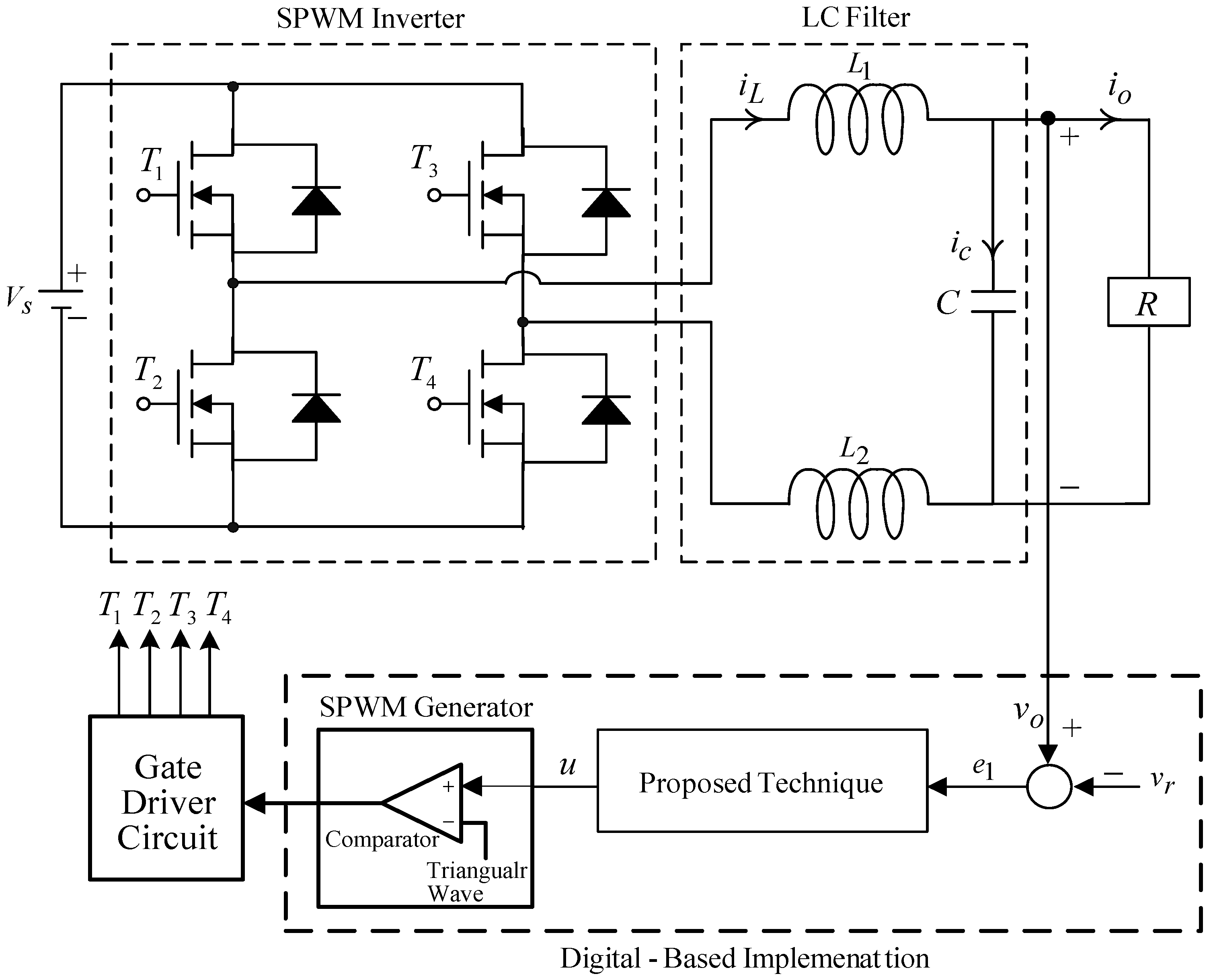
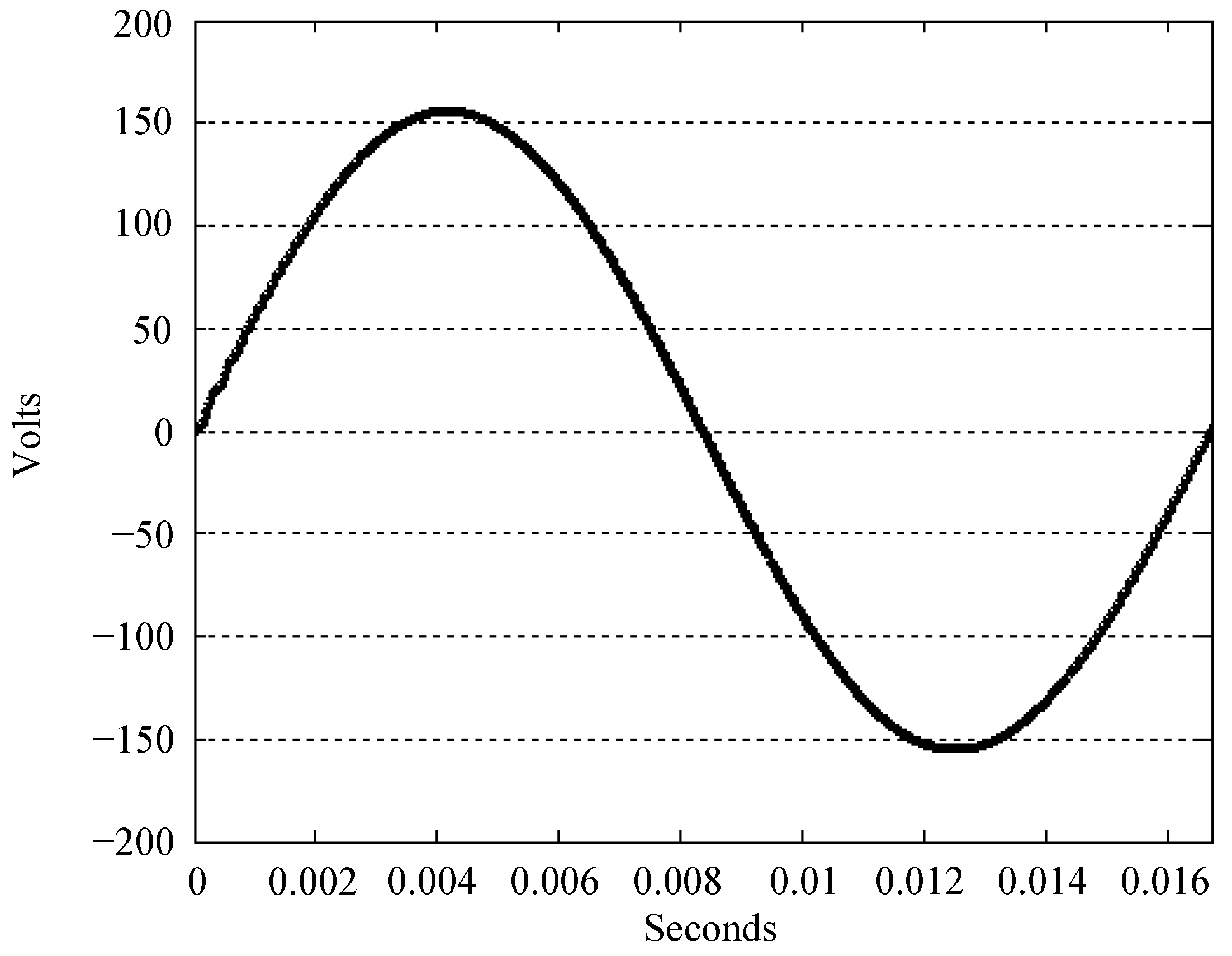
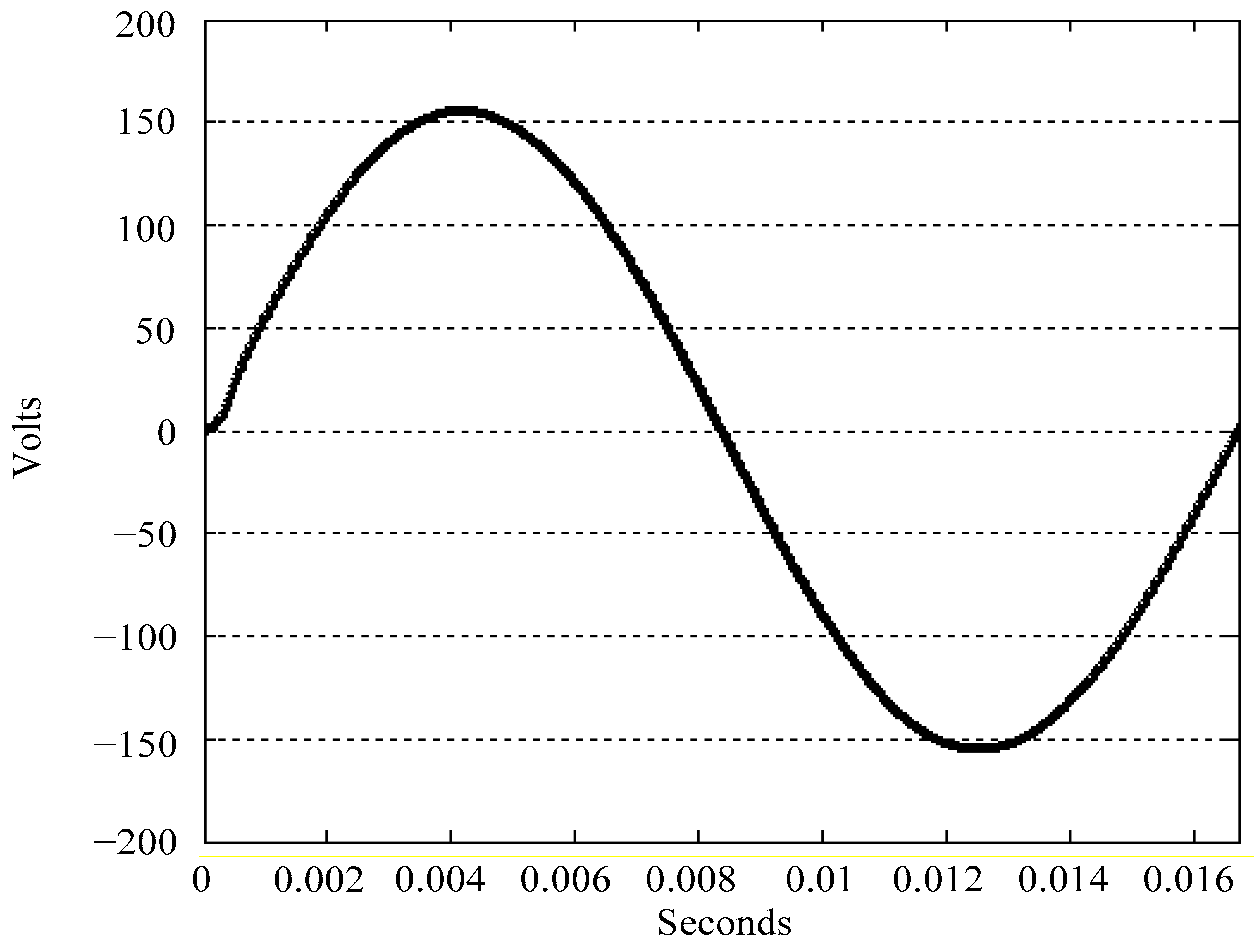
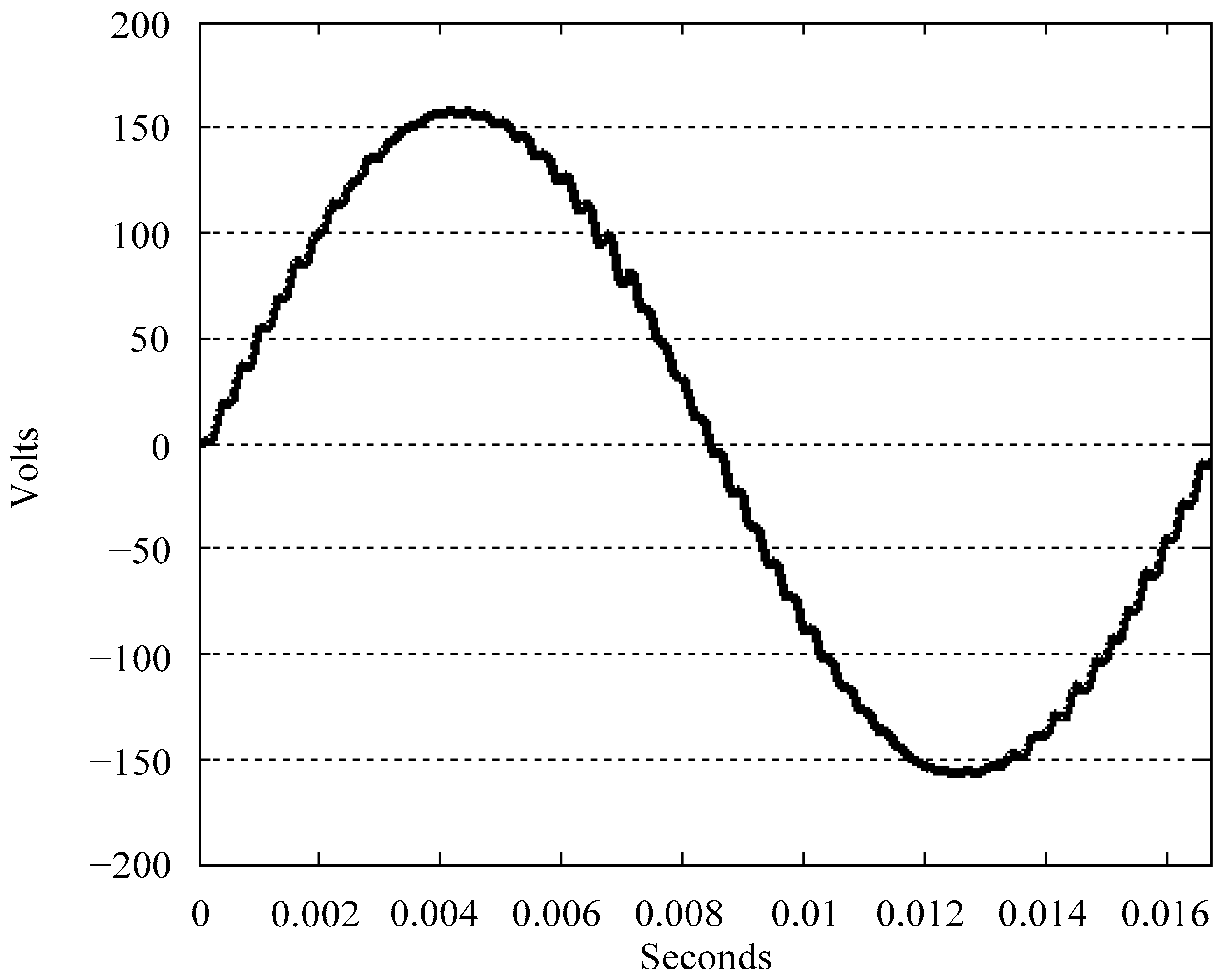
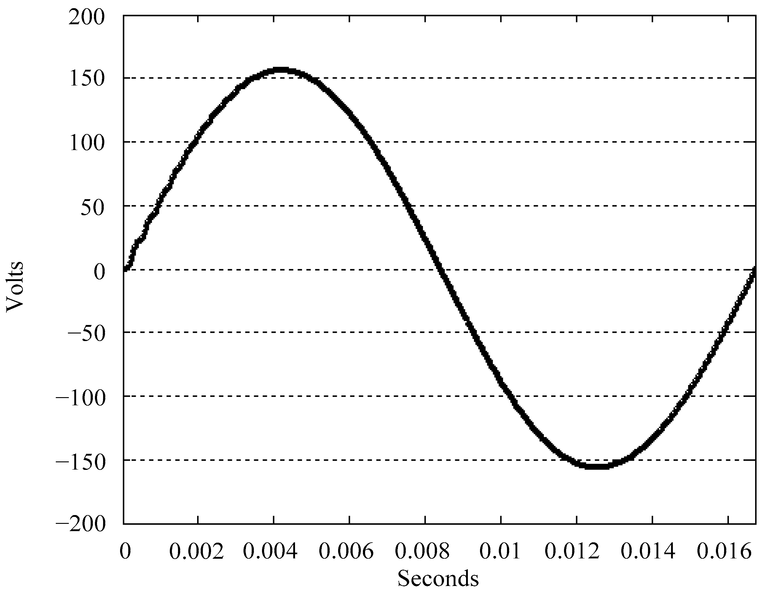
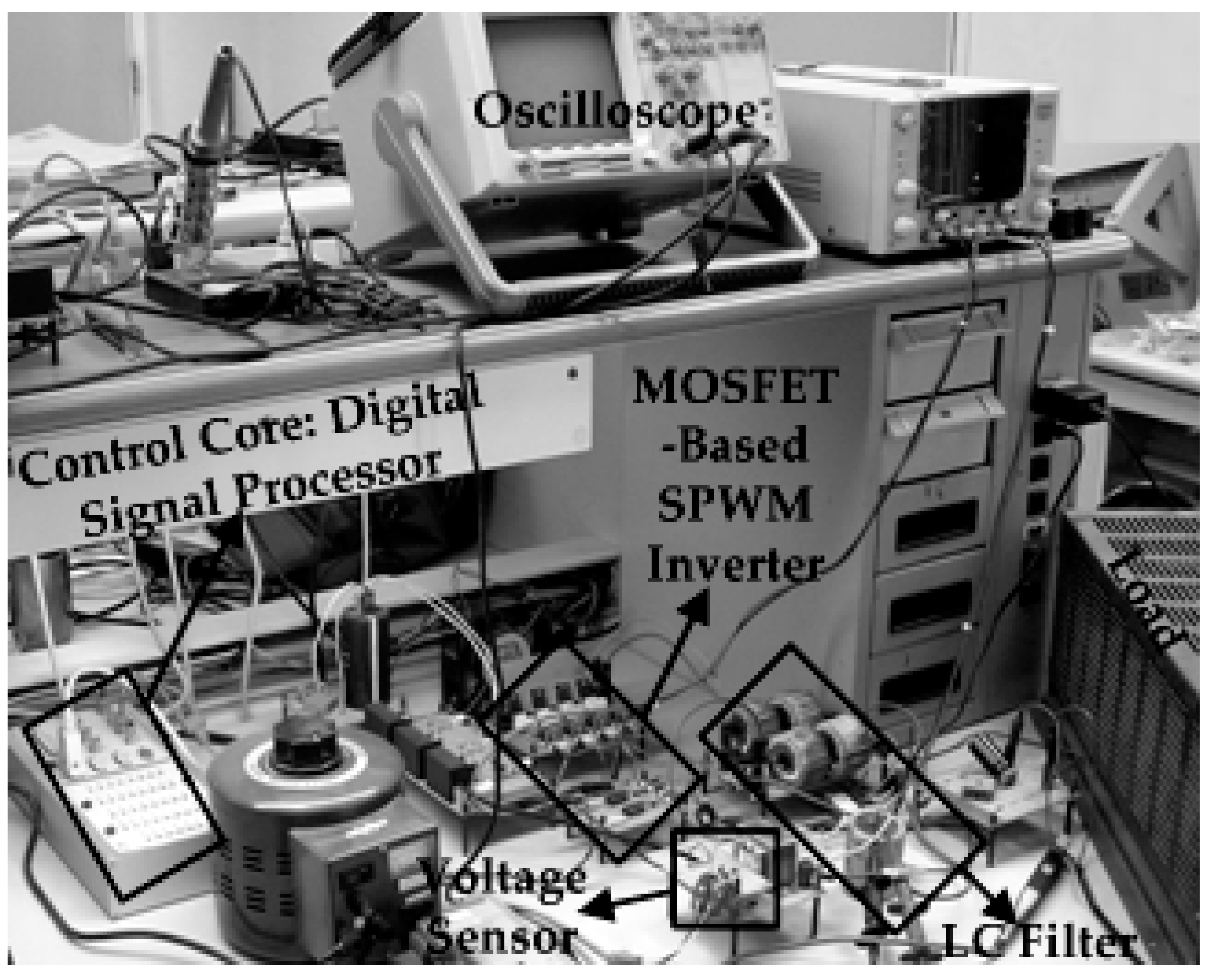
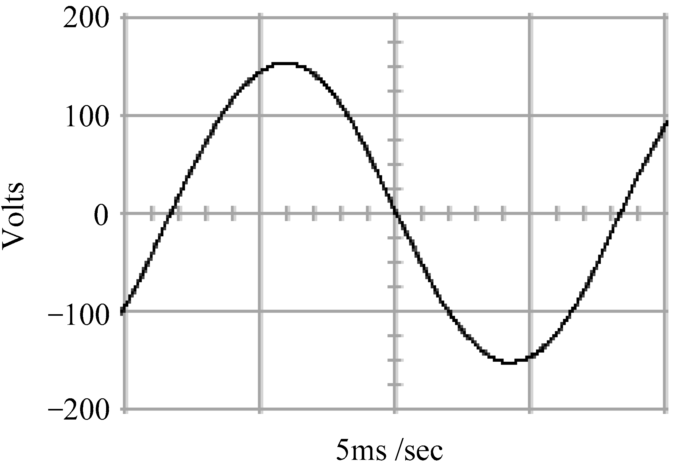
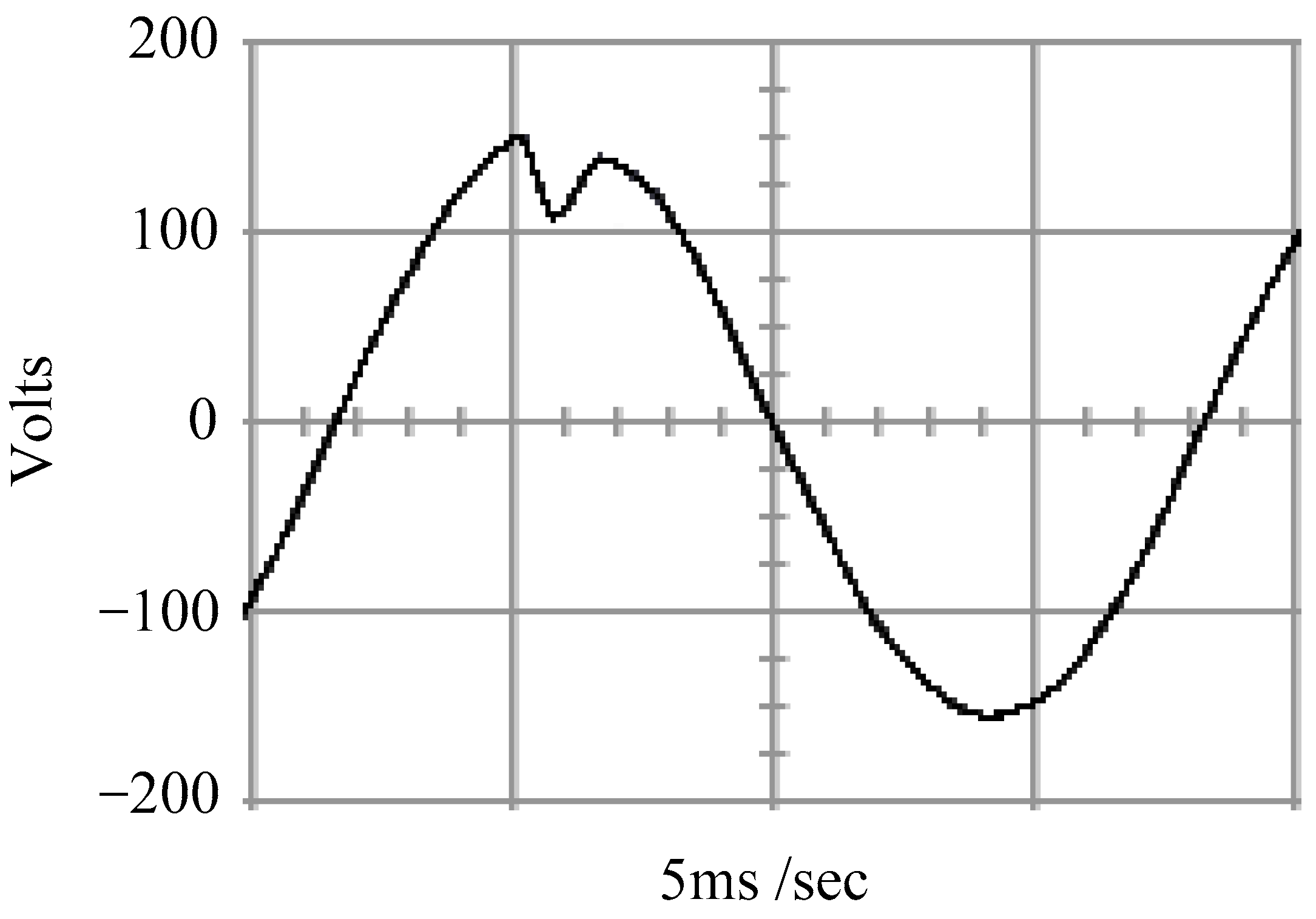
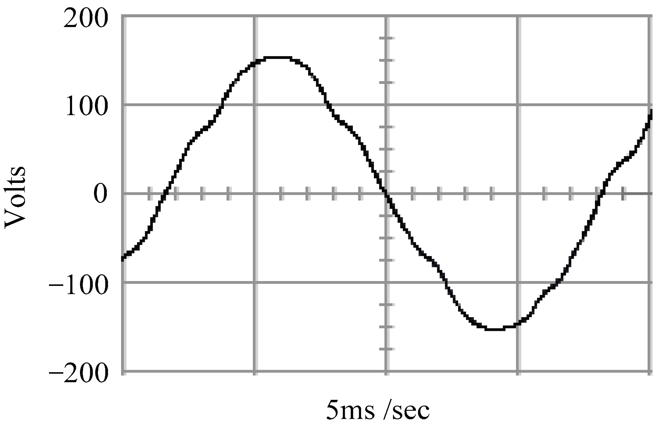
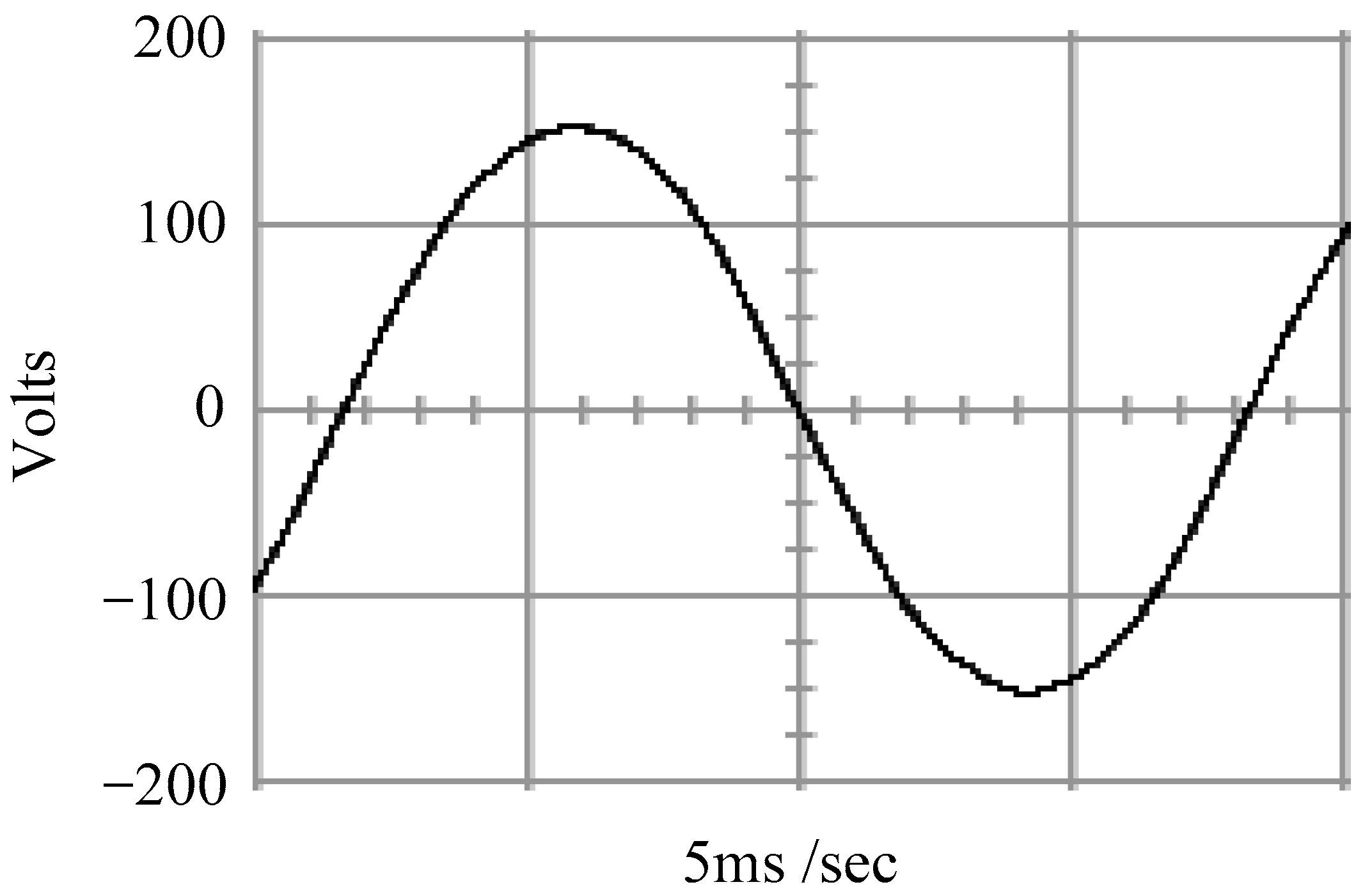
4. Simulation and Experimental Results

Based on the mathematical model of the single-phase SPWM inverter, the parameters are shown in Table 1.
Figure 2 and Figure 3, respectively, depict the simulated output waveforms of the single-phase SPWM inverter with a fully resistive load for the conventional SMC and the proposed technique. As the load is a linear resistive load without dynamic changing, the output voltages of both the conventional and the proposed inverter approach very closely to sine waves. A detailed inspection of the two output-voltage waveforms shows that there are only quite short transient phenomena at the beginning of the waveforms, after which the steady-state reactions remain nearly distortion-free. The simulated output voltage of the single-phase SPWM inverter operated by the conventional SMC under a stepped load (no load to full load) is displayed in Figure 4. With the corresponding load case, Figure 5 depicts the simulated output voltage of the proposed single-phase SPWM inverter. It can be detected from Figure 5 that the proposed single-phase SPWM inverter not only obtains less transient voltage degradation, but also rapidly remedies the voltage drop back to the reference voltage value. While the conventional SMC makes the instantaneous voltage sink to about one hundred voltages and then recover to close to the reference voltage, the proposed technique not only results in a lower voltage drop and shorter recovery time, but also completely brings the voltage to the required sine wave voltage. Figure 6 shows the simulated output voltage of the conventional sliding mode-controlled single-phase SPWM inverter as the filter parameters are varied. Figure 7 plots the simulated output voltages of the proposed single-phase SPWM inverter subject to fluctuations in the filter parameters. The proposed single-phase SPWM inverter exhibits significant insensitivity, having an approximately sinusoidal output voltage, whereas the conventional sliding mode-controlled single-phase SPWM inverter suffers from a high level distortion in the output voltage waveform. The proposed technique features high robustness against changes in internal parameters providing a superior steady state, whereas the conventional SMC easily affects the waveform even with the minor changes in internal parameters, leading to severe distortion and deformation. The proposed algorithm and the SPWM module are designed in MATLAB (version 6.1, MathWorks Inc., Natick, MA, USA)/Simulink (version 4.1, MathWorks Inc., Natick, MA, USA) software. Real Time workshop auto-generates the C code, which is permitted to run on the hardware (dSPACE digital signal processor). The implementation in the hardware is depicted in Figure 8, which illustrates the inference circuit between the digital signal processor as well as the single-phase SPWM inverter. There are four optocouplers (PC923) taken to provide the isolation among the control as well as the power circuits. The power MOSFET used is the IRF460. The voltage sensor employed is an AD202 isolation amplifier. Figure 9 and Figure 10 show the experimental steady-state output voltages of the single-phase SPWM inverter using the conventional SMC and proposed technique at full resistive loads. Both output voltages have good regulation with low harmonic distorted AC waveform. Because the load is linear without any variation or non-linearity, pure sine waveforms can be obtained with either the conventional SMC or the proposed technique. The experimental waveform achieved with the conventional SMC, under a stepped load from no load to full load at a 90 degree firing angle presented in Figure 11, contains a major voltage droop with a delayed restoration period. When a conventional SMC inverter is operated during no load condition, the output voltage maintains a good sinusoidal steady state. Once it suddenly becomes full-load operation, the output voltage drops to nearly one hundred voltages and cannot quickly return to the required sine wave output-voltage amplitude during the transient conversion. Conversely, Figure 12 reveals the experimental waveform acquired using the proposed technique under a stepped load of 90 degree ignition angle from no load to full load. A satisfactory transient can be observed along with a little voltage droop after which the voltage waveform comes back to a good level of steady-state precision. The proposed technique uses a non-linear sliding function and GMM predictive compensation, resulting in minor output voltage drop along with a faster recovery to one hundred and ten voltages (root-mean-square value). For a single-phase SPWM inverter with a resistance of 12 ohms, the values of the LC filter parameters are supposed to be between 50% and 100% of the nominal value. Figure 13 and Figure 14 display the experimental output voltage waveforms of a single-phase SPWM inverter which is separately managed by the conventional SMC and proposed technique. The proposed technique is less sensitive to parametric variations as well as loading perturbations as compared to the conventional SMC. The filter of the inverter is the important element for filtering harmonics, which can detect the effectiveness of the designed control method in the case of changing filter parameters. The proposed technique clearly has a good steady-state output behavior for filter parameter variations, while the conventional SMC produces distorted sine wave with high %THD. The proposed technique yields desirable steady-state and dynamic reactions as well as exhibiting noticeable enhancement in terms of decreasing output-voltage distortion subject to filter parametric variations. Table 2 shows the simulated and experimental voltage droop and %THD. In the final conclusion, the voltage THD needs to be less than 5% as recommended by the IEEE standard 519-1992. In addition, according to the recommendation of Institute of Electrical and Electronics Engineers (IEEE) standard 1159-1995, the voltage drop should be the reduction in root-mean-square voltage/current at the source frequency from 0.5 cycles to one minute period; normal values of voltage drop vary in the range of 0.1 and 0.9 per unit. Both the simulation and experimental results indicate that the proposed technique meets the above IEEE standards.

5. Conclusions

This paper illustrates a single-phase SPWM inverter governed by a digital signal processor to demonstrate the proposed technique. Contrasting with a conventional SMC, the ASMC features a fast state convergence time of the system, which creates a better reaction in both transient and steady state. In addition, the GMM contributes to the cancellation of the chattering arising in the ASMC in case the load becomes a heavily non-linear ambience. The proposed single-phase SPWM inverter is able to deliver a high-quality AC output voltage when coupled with the ASMC and GMM. As the simulation and experimental results showed, the proposed controlled single-phase SPWM inverter allows for low total harmonic distortion, fast transience, removal of chattering as well as steady-state errors under different operating load requirements. In future studies, the proposed single-phase SPWM inverter can be combined with a non-inverting buck–boost DC–DC converter (as shown in Figure 15) to extend its application in photovoltaic systems [42,43,44,45,46].

Author Contributions

E.-C.C. conceived and investigated the algorithm, designed the circuit and developed the methodology; R.-C.W., H.H.C. and C.-A.C. prepared the software resources and set up the simulation software; E.-C.C. performed control system simulations; E.-C.C. carried out experiments, analyzed the results, wrote the paper and revised it for submission. All authors have read and agreed to the published version of the manuscript.

Funding

This research was funded by the National Science and Technology Council (NSTC) (formerly the Ministry of Science and Technology (MOST)) of Taiwan, under contract numbers MOST 110-2221-E-214-021.

Data Availability Statement

Not applicable.

Acknowledgments

The authors would like to thank the research project (MOST 110-2221-E-214-021) of National Science and Technology Council (NSTC) (formerly the Ministry of Science and Technology (MOST)), Taiwan for the support of simulation equipment, experimental materials and devices.

Conflicts of Interest

The authors declare no conflict of interest.

References

  1. Batarseh, I.; Harb, A. Power Electronics: Circuit Analysis and Design; Springer International Publishing: New York, NY, USA, 2018. [Google Scholar]
  2. Mohanty, P.; Muneer, T.; Tariq, K.; Mohan, L. Solar Photovoltaic System Applications; Springer: New York, NY, USA, 2015. [Google Scholar]
  3. Branko, L.D.; Branko, B. Power Electronics: Converters and Regulators; Springer: New York, NY, USA, 2015. [Google Scholar]
  4. Mahmoud, M.S. Microgrid: Advanced Control Methods and Renewable Energy System Integration; Elsevier Science Ltd.: Amsterdam, The Netherlands, 2016. [Google Scholar]
  5. Chen, T.F.; Dutta, O.; Ramasubramanian, D.; Farantatos, E. An LQR-based Robust Voltage Controller for Grid Forming Inverters during Blackstart. In Proceedings of the 2021 IEEE PES Innovative Smart Grid Technologies–Asia (ISGT Asia), Brisbane, Australia, 5–8 December 2021; pp. 1–5. [Google Scholar]
  6. Kanathipan, K.; Lam, J. An Electrolytic Capacitor-Less PV Micro-Inverter Based on CLL Resonant Conversion with a Power Control Scheme Using Resonant Circuit Voltage Control Loops. CPSS Trans. Power Electron. Appl. 2022, 7, 139–149. [Google Scholar] [CrossRef]
  7. Krüner, S.; Song, Z.; Hackl, C.M. 3D-Modulation and PI State-Feedback Control of Voltage Source Inverters with Split DC-Link. In Proceedings of the 2021 IEEE 30th International Symposium on Industrial Electronics (ISIE), Kyoto, Japan, 20–23 June 2021; pp. 1–7. [Google Scholar]
  8. Vadi, S.; Bayindir, R. Modeling, Analysis and Proportional Resonant and Proportional Integral Based Control Strategy for Single Phase Quasi-Z Source Inverters. IEEE Access 2022, 10, 87217–87226. [Google Scholar] [CrossRef]
  9. Yildiran, N.; Tacer, E. A New Approach to H-Infinity Control for Grid-Connected Inverters in Photovoltaic Generation Systems. Electr. Power Compon. Syst. 2019, 47, 1413–1422. [Google Scholar] [CrossRef]
  10. Azar, A.T.; Zhu, Q.M. Advances and Applications in Sliding Mode Control Systems; Springer: New York, NY, USA, 2015. [Google Scholar]
  11. Wu, L.G.; Shi, P.; Su, X.J. Sliding Mode Control of Uncertain Parameter-Switching Hybrid Systems; Wiley: Chichester, UK, 2014. [Google Scholar]
  12. Utkin, V.I. Variable Structure Systems with Sliding Modes. IEEE Trans. Autom. Control 1977, AC-22, 212–222. [Google Scholar] [CrossRef]
  13. Vaidyanathan, S.; Lien, C.H. Applications of Sliding Mode Control in Science and Engineering; Springer: New York, NY, USA, 2017. [Google Scholar]
  14. Chinnappan, R.; Logamani, P.; Ramasubbu, R. Fixed Frequency Integral Sliding-Mmode Current-Controlled MPPT Boost Converter for Two-Stage PV Generation System. IET Circuits Devices Syst. 2019, 13, 793–805. [Google Scholar] [CrossRef]
  15. Banerjee, B.; Weaver, W.W. Generalized Geometric Control Manifolds of Power Converters in a DC Microgrid. IEEE Trans. Energy Convers. 2014, 29, 904–912. [Google Scholar] [CrossRef]
  16. Feshara, H.F.; Ibrahim, A.M.; El-Amary, N.H.; Sharaf, S.M. Performance Evaluation of Variable Structure Controller Based on Sliding Mode Technique for a Grid-Connected Solar Network. IEEE Access 2019, 7, 84349–84359. [Google Scholar] [CrossRef]
  17. Hao, X.; Yang, X.; Liu, T.; Huang, L.; Chen, W.J. A Sliding-Mode Controller with Multiresonant Sliding Surface for Single-Phase Grid-Connected VSI with an LCL Filter. IEEE Trans. Power Electron. 2013, 28, 2259–2268. [Google Scholar] [CrossRef]
  18. Abrishamifar, A.; Ahmad, A.A.; Mohamadian, M. Fixed Switching Frequency Sliding Mode Control for Single-Phase Unipolar Inverters. IEEE Trans. Power Electron. 2012, 27, 2507–2514. [Google Scholar] [CrossRef]
  19. Komurcugil, H. Rotating-Sliding-Line-Based Sliding-Mode Control for Single-Phase UPS Inverters. IEEE Trans. Ind. Electron. 2012, 59, 3719–3726. [Google Scholar] [CrossRef]
  20. Aghatehrani, R.; Kavasseri, R. Sensitivity-Analysis-Based Sliding Mode Control for Voltage Regulation in Microgrids. IEEE Trans. Sustain. Energy 2013, 4, 50–57. [Google Scholar] [CrossRef]
  21. Janardhanan, S.; Bandyopadhyay, B. On Discretization of Continuous-Time Terminal Sliding Mode. IEEE Trans. Autom. Control 2006, 51, 1532–1536. [Google Scholar] [CrossRef]
  22. Galias, Z.; Yu, X.H. Dynamical Behaviors of Discretized Second-Order Terminal Sliding-Mode Control Systems. IEEE Trans. Circuits Syst. II Express Briefs 2013, 59, 597–601. [Google Scholar] [CrossRef]
  23. Abidi, K.; Xu, J.X.; She, J.H. A Discrete-Time Terminal Sliding-Mode Control Approach Applied to a Motion Control Problem. IEEE Trans. Ind. Electron. 2009, 56, 3619–3627. [Google Scholar] [CrossRef]
  24. Zhao, Y.X.; Wu, T.; Ma, Y. A Double Power Reaching Law of Sliding Mode Control Based on Neural Network. Math. Probl. Eng. 2013, 2013, 1–9. [Google Scholar] [CrossRef] [Green Version]
  25. Wang, H.P.; Zhao, X.K.; Tian, Y. Trajectory Tracking Control of XY Table Using Sliding Mode Adaptive Control Based on Fast Double Power Reaching Law. Asian J. Control 2016, 18, 2263–2271. [Google Scholar] [CrossRef]
  26. Dong, C.Y.; Wang, H.J.; Cui, W.Y. Application of the Sliding Mode Control Approach Based on Double Power Exponential Reaching Law for the Hydraulic Servo System. Appl. Mech. Mater. 2015, 741, 655–658. [Google Scholar] [CrossRef]
  27. Han, Y.X.; Cheng, Y.; Xu, G.W. Trajectory Tracking Control of AGV Based on Sliding Mode Control with the Improved Reaching Law. IEEE Access 2019, 7, 20748–20755. [Google Scholar] [CrossRef]
  28. Andrzej, B.; Paweł, L. A Generalization of Gao’s Reaching Law for Higher Relative Degree Sliding Variables. IEEE Trans. Autom. Control 2018, 63, 3173–3179. [Google Scholar]
  29. Peltoniemi, P.; Nuutinen, P.; Pyrhonen, J. Observer-based output voltage control for DC power distribution purposes. IEEE Trans. Power Electron. 2013, 28, 1914–1926. [Google Scholar] [CrossRef]
  30. Lin, S.Y.; Zhang, W.D.; Wang, H. Controller Designed via an Adaptive Reaching Law for DSMC Systems. IEEE Trans. Circuits Syst. II Express Briefs 2020, 62, 330–334. [Google Scholar] [CrossRef]
  31. Wu, X.B.; Liu, Q.; Zhao, M.L.; Chen, M.Y. Monolithic Quasi-Sliding-Mode Controller for SIDO Buck Converter with a Self-Adaptive Free-Wheeling Current Level. J. Semicond. 2013, 34, 1–7. [Google Scholar] [CrossRef]
  32. Xu, G.R.; Teng, Q.F.; Zheng, X.W.; Ma, X.P. An Adaptive Backstepping Sliding Mode Control Strategy for Single-phase Grid-Connected Inverter System under Weak Grid. In Proceedings of the 2021 China Automation Congress (CAC), Beijing, China, 22–24 October 2021; pp. 5684–5689. [Google Scholar]
  33. Liu, S.; Lin, Y. Grey Information: Theory and Practical Applications; Springer: London, UK, 2006. [Google Scholar]
  34. Deng, J.L. Introduction to Grey System Theory. J. Grey System. 1989, 1, 1–24. [Google Scholar]
  35. Li, Q.X.; Lin, Y. Review paper: A Briefing to Grey Systems Theory. J. Syst. Sci. Inf. 2014, 2, 178–192. [Google Scholar] [CrossRef] [Green Version]
  36. Sun, X.; Sun, W.; Wang, J.; Gao, Y. Using a Grey-Markov Model Optimized by Cuckoo Search Algorithm to Forecast the Annual Foreign Tourist Arrivals to China. Tour. Manag. 2016, 52, 369–379. [Google Scholar] [CrossRef]
  37. Mao, Z.L.; Sun, J.H. Application of Grey-Markov model in forecasting fire accidents. Procedia Eng. 2011, 11, 314–318. [Google Scholar]
  38. Chen, X.; Fang, P.; Chen, F.L.; Wang, S. The Grey Markov Chain Model Based on Sliding Window in Vertical Steering Locus Forecasting for Shearers. In Proceedings of the 2019 International Conference on Advances in Construction Machinery and Vehicle Engineering (ICACMVE), Changsha, China, 14–16 May 2019; pp. 426–429. [Google Scholar]
  39. Lehman, B.; Bass, R.M. Extension of averaging theory for power electronic systems. IEEE Trans. Power Electron. 1996, 11, 542–553. [Google Scholar] [CrossRef] [Green Version]
  40. Middlebrook, R.D. Small-signal modeling of pulse-width modulated switched mode power converters. Proc. IEEE 1988, 76, 343–354. [Google Scholar] [CrossRef] [Green Version]
  41. Mahdavi, J.; Emaadi, S.; Ehsani, M. Analysis of power electronic converters using the generalized state-space averaging approach. IEEE Trans. Circuits Syst. I Fundam. Theory Appl. 1997, 44, 767–770. [Google Scholar] [CrossRef] [Green Version]
  42. Callegaro, L.; Pagano, D.J.; Ciobotaru, M.; Fletcher, J.E. Feedback linearization control of non-inverting buck-boost PV power optimizers. In Proceedings of the 2017 IEEE 8th International Symposium on Power Electronics for Distributed Generation Systems (PEDG), Florianopolis, Brazil, 17–20 April 2017; pp. 1–6. [Google Scholar]
  43. Ogudo, K.A.; Umenne, P. Design of a PV Based Power Supply with a NonInverting Buck-Boost Converter. In Proceedings of the 2019 IEEE PES/IAS PowerAfrica, Abuja, Nigeria, 20–23 August 2019; pp. 545–549. [Google Scholar]
  44. Mishra, T. Synthesis and Modelling of A Novel Multi-Input Multi-Output System Topology Implemented on Non-Inverting Buck-Boost Converter for Renewable Energy Applications. In Proceedings of the 2022 First International Conference on Electrical, Electronics, Information and Communication Technologies (ICEEICT), Trichy, India, 16–18 February 2022; pp. 1–6. [Google Scholar]
  45. Callegaro, L.; Ciobotaru, M.; Pagano, D.J.; Turano, E.; Fletcher, J.E. A Simple Smooth Transition Technique for the Noninverting Buck–Boost Converter. IEEE Trans. Power Electron. 2018, 33, 4906–4915. [Google Scholar] [CrossRef]
  46. Boutebba, O.; Semcheddine, S.; Krim, F.; Corti, F.; Reatti, A.; Grasso, F. A Nonlinear Back-stepping Controller of DC-DC Non Inverting Buck-Boost Converter for Maximizing Photovoltaic Power Extraction. In Proceedings of the 2020 IEEE International Conference on Environment and Electrical Engineering and 2020 IEEE Industrial and Commercial Power Systems Europe (EEEIC/I&CPS Europe), Madrid, Spain, 9–12 June 2020; pp. 1–6. [Google Scholar]
Figure 1. Block diagram of a single-phase SPWM inverter.
Processes 11 00013 g001
Figure 2. Simulated output voltage with the conventional SMC under full load.
Processes 11 00013 g002
Figure 3. Simulated output voltage with the proposed technique under full load.
Processes 11 00013 g003
Figure 4. Simulated output voltage with the conventional SMC under stepped load.
Processes 11 00013 g004
Figure 5. Simulated output voltage with the proposed technique under stepped load.
Processes 11 00013 g005
Figure 6. Simulated output voltage with the conventional SMC under LC parametric variations.
Processes 11 00013 g006
Figure 7. Simulated output voltage with the proposed technique under LC parametric variations.
Processes 11 00013 g007
Figure 8. Circuits of hardware implementation.
Processes 11 00013 g008
Figure 9. Experimental output voltage with the conventional SMC under full load.
Processes 11 00013 g009
Figure 10. Experimental output voltage with the proposed technique under full load.
Processes 11 00013 g010
Figure 11. Experimental output voltage with the conventional SMC under stepped load.
Processes 11 00013 g011
Figure 12. Experimental output voltage with the proposed technique under stepped load.
Processes 11 00013 g012
Figure 13. Experimental output voltage with the conventional SMC under LC parametric variations.
Processes 11 00013 g013
Figure 14. Experimental output voltage with the proposed technique under LC parametric variations).
Processes 11 00013 g014
Figure 15. Circuit structure of a non-inverting buck-boost DC–DC converter.
Processes 11 00013 g015
Table 1. Parameters of the single-phase SPWM inverter.
ParametersValues
DC supply voltage ( V s )200 V
Sine output voltage ( v o ) 110 2 Vmax
Frequency of sine output voltage60 Hz
Filter inductor ( L )1 mH
Filter capacitor ( C ) 20 Microfarad
Resistive load ( R )12 Ohm
Switching frequency30 kHz
Table 2. Simulated and experimental voltage droop and %THD.
MethodsTesting ConditionsValues
Conventional SMC
(Simulations)
Full resistive load (%THD)0.02%
Stepped load (Voltage droop)50.79 Vmax
LC parametric variation (%THD)21.43%
Proposed
Technique
(Simulations)
Full resistive load (%THD)0.01%
Stepped load (Voltage droop)16.83 Vmax
LC parametric variation (%THD)0.09%
Conventional SMC
(Experiments)
Full resistive load (%THD)0.03%
Stepped load (Voltage droop)50.46 Vmax
LC parametric variation (%THD)19.76%
Proposed Technique
(Experiments)
Full resistive load (%THD)0.04%
Stepped load (Voltage droop)21.17 Vmax
LC parametric variation (%THD)0.08%
Disclaimer/Publisher’s Note: The statements, opinions and data contained in all publications are solely those of the individual author(s) and contributor(s) and not of MDPI and/or the editor(s). MDPI and/or the editor(s) disclaim responsibility for any injury to people or property resulting from any ideas, methods, instructions or products referred to in the content.

