1. Introduction
The annual increase in the production of grain and oilseeds puts forward the problem of intensifying the postharvest processing of grain and improving the quality of cleaning, separation and special processing of the resulting products. One of the ways to intensify processing and improve the quality indicators of grain is the use of the technology of fractionation of the collected grain material according to the visual signs of separation. These signs provide separation into separate fractions of grain with indicators characterizing the seed, nutritional and fodder value of each received fraction. It is advisable to use a simple and reliable method of air separation of grain material components according to aerodynamic properties for the technical implementation of fractional technology. As is known, there is a fairly close correlation (coefficient of determination R2 = 0.90–0.92) between the qualitative (biological) indicators of individual grains and them terminal velocity. Therefore, the air flow can sort the grain according to its quality indicators (mass, density). As a result, seeds with a high terminal velocity have a better biological value.
The separation of the grain material by the air flow is carried out on the basis of the fact that, as a result of the forceful action of the air flow, the grains in it move along different trajectories. The nature of the trajectories of movement of grains of different density depends on the value and direction of the external, mass and aerodynamic (surface) forces acting on them. The principle of air separation of the grain material is based on the difference in the aerodynamic properties of the components of the grain material. The main indicator of the aerodynamic properties of grains which determines the possibility and efficiency of separation of components in air flows is the terminal velocity.
Three main methods of separating grain material are used in modern designs of grain separating machines, depending on the scheme of interaction between the air flow and grain. These are separation in horizontal air flow, separation in vertical air flow and separation in inclined air flow.
Horizontal and inclined air flows have certain advantages because the direction of gravity and aerodynamic force in them do not coincide. The force of gravity ensures the separation of the main (heavy) component of the grain material from the air flow and the aerodynamic force moves the lighter components along the flow, which makes it possible to separate the grain material into several fractions [
1].
Vertical flows provide a higher separation quality with small grain material feeds into the pneumatic separation channel [
2,
3,
4]. With an increase in the supply of material, the efficiency of their fractionation decreases. This is due to the fact that grains move up and down a large number of times in the vertical air channel. As a result, their stochastic collision occurs especially with an increased feeding of grain material which significantly reduces the quality of division. However, in vertical pneumatic separating channels, the air flow affects the grain material for a longer time due to the significant height, which makes it possible to remove light components more efficiently through elutriation [
5,
6,
7].
The most widespread methods in the world practice of air grain separation are vertical channels of rectangular cross section with lateral material supply [
8,
9,
10].
The feeders of such pneumatic separators predetermine the structural delimitation of the air flow in height. The lower part serves to remove (descent) heavy grains. The upper part serves to take out the light components of the grain material, as well as to return heavy (medium) grains down. Grain material is divided into only two fractions: pure (high grade) seeds and garbage impurities. However, there is no exact division into two fractions in such channels. The unevenness of the air flow and the change in the orientation of long grains lead to the fact that some of the quality grains are carried out by air into the garbage fraction and some of the impurities (broken and spoiled grains) descend into the pure grain fraction. At the same time, the greater the concentration of grains in the working area (input zone), the less clear the division into constituent components becomes.
To increase the efficiency of separating grain material, structural improvements are used in the form of guide grids in the upper part of the channel to equalize the air flow [
11,
12,
13]. However, this is ineffective, since the dense flow of grain material at the inlet to the air flow increases the air speed in the intergrain space unevenly, and the uniformity of the air flow speed is violated.
To eliminate this shortcoming, various structural and technological methods are used, in particular, the stratification of the grain mixture by an air flow on the scaly surface of the feeding device [
14,
15,
16]. According to the authors, this makes it possible to increase the specific load and improve the quality of cleaning.
Another way to increase the productivity and quality of cleaning and fractionation of grain material in a vertical channel is the use of multi-flow introduction of grain material into the channel [
3,
11,
17,
18,
19]. At the same time, grain streams (monolayers) are formed, which create grain microchannel when the grain material is introduced into the air flow. According to the authors, this helps reduce the aerodynamic resistance of the grain mixture and align the velocity field of the air flow.
There are ways to introduce material by a cascade of inclined guide trays and to throw grains into the channel by a rotary drum with blades [
20,
21,
22]. However, the use of the above method does not exclude the intersection of the trajectories of movement of the grains of the heavy fraction with the trajectories of the movement of light fractions. Accordingly, it is possible for light impurities to enter the heavy fraction and to carry out the grain with light impurities, although it significantly reduces their amount. In addition, the considered methods do not allow separation into more than two fractions.
The emergence of new designs of pneumatic separators with a vertical channel and a lower zone for separating and unloading individual fractions [
6,
23,
24] makes it possible to use the method of separating grain material components according to the divergence (branching) of their movement trajectories. This is a promising direction in the improvement of pneumatic separators with a vertical channel.
In [
10,
25,
26], a pneumatic gravity separator was substantiated and studied, in which the separation of grain material according to aerodynamic properties is implemented using the lower part of a channel with an annular section for separating seeds. The use of an annular channel with a conical feeder makes it possible to introduce grain in a monolayer, while the trajectories of the grains diverge in the channel in a radial direction, which makes it possible to avoid collision.
In [
27], the annular pneumatic separating channel was improved by providing a self-oscillating mode of movement of the central tube with sail elements placed on the tube. In the process of rotational oscillations, the sail elements should generate an additional radial air flow, which should intensify the divergence of the trajectories and the separation of sunflower seeds into medium and heavy fractions.
An analysis of the studies carried out in [
28,
29] revealed a number of significant shortcomings, both in the design of separators and in research methods. In particular, a uniform air flow is not ensured in the cross section of the pneumatic separating channels. Near the walls of the channels, there are zones in which the velocity is equal to zero. Rectangular channels also have corner dead zones. The grain material interacts with the flow in the material input zone for a fairly short time.
As for pneumatic separators with a vibrating pipe, the sail elements create additional hydraulic resistance. The turbulence of the air flow contributes to its movement, and the grains of the middle fraction fall into the gathering of the heavy fraction. Under these conditions, the impact of grains on the walls of the pneumatic channel is observed.
A significant number of works are devoted to theoretical studies of mathematical modeling of the processes of grain movement in aspiration channels [
29,
30]. However, in these works, the movement of grains is considered without taking into account the unevenness of air velocities in the channels and the impact of grains on the walls.
At the same time [
28], shows the possibility of taking into account the non-uniformity of the air flow and the action of lateral forces of the Magnus and Zhukovsky types. Improved mathematical models of grain dynamics in non-uniform air flows have been obtained. However, the possibilities of the impact of air structures on the grain material in the separating channels are still not used enough. The reason for this is the insufficient knowledge of the processes of interaction of the components of the grain material with an uneven air flow, including with an artificially formed field of air flow velocities.
In this article, the authors attempted to use the artificially formed field of air flow velocities in the transverse and longitudinal sections of the channel to direct alternative lateral forces in order to increase the interaction time of the air flow and grains and increase the divergence (splitting) of the trajectories of movement of individual components of the grain material.
2. Materials and Methods
Modeling of the air flow field in a vertical annular channel was carried out using computational fluid dynamics (CFD) methods by solving the unsteady Navier–Stokes equations [
2]. To identify the possibilities of changing the pattern of the velocity field of the air flow in a vertical annular channel, the distribution of air velocity and pressure vectors was studied using the FlowVision software. A discrete particle model (DPM) [
31] was used to mathematically describe the dynamics of grain movement in an uneven velocity field of an air flow. The calculations are based on the use of D’Alembert’s principle and are implemented using MathCad software. The plot of the air flow velocity in the cross section of the vertical annular channel was determined by modeling. Various geometries of the air separating channel were studied, with a constant cross-sectional area along the height and its change in the direction of air flow. The study was carried out for different values of air flow speeds from 5 to 10 m/s in the channel.
The separation efficiency of grain material components was determined by trajectory analysis. The distance between the trajectories of movement of grains of three conditional fractions was taken as an efficiency criterion: heavy, medium and light grains. A quantitative assessment of the belonging of a caryopsis to a certain fraction was determined by the grain terminal velocity, which was previously determined according to the experimental data [
26].
To take into account and quantify the value of the separation index in the mathematical description of the process of movement of grains in air space, the coefficient of proportionality of aerodynamic drag was used, which is determined from the known relation [
26,
28]:
where
ξ(Re) is the drag coefficient, which is a function of the Reynolds number,
;
ν is coefficient of kinematic viscosity (m
2 c
−1);
is air density (kg m
−3);
S is the area of the copper section of the grain, normal to the vector
(m
2);
u is the flow velocity around the grain (relative air velocity) (m s
−1);
m is the weight of the grain (kg);
is the grain terminal velocity (average for each fraction) (m s
−1);
g is the free fall acceleration (m s
−2).
The mathematical description of the dynamics of grain movement in an uneven high-speed field of the air flow was formed on the basis of the scheme of the force interaction of the grain with the air flow under the accepted assumptions. The air flow is stationary, unchanged in time. The grain is round, unchanged, and does not interact with each other and with the walls. The air velocity distribution is described by the equation Va (x) = V (x, y), where x and y are grain coordinates in the air flow field. The grain movement is considered as planar in the xOy rectangular coordinate system. When leaving the feeder, the grain acquires a torque in the direction coinciding with the air flow velocity vector. A grain represented as a material point with a mass m is subject to the following forces: gravity , aerodynamic drag , Magnus-type side forces and Zhukovsky type . The forces of Archimedes, electrostatic, thermodynamic and others are neglected because of their smallness.
The force of aerodynamic resistance (reaction of the air flow) in the turbulent mode of movement of the air flow is proportional to the square of the speed of the air flow around the grain and, taking into account the value of
, is determined by the formula [
26,
28]:
where
is relative velocity (flow velocity);
is air flow velocity;
is the grain velocity.
The value of the lateral forces for a plane-parallel flow according to the Kutta–Zhukovsky theorem is proportional to the relative speed of the oncoming air flow
and circulation
and is determined by the formula [
19,
29]:
The aerodynamic resistance vector is directed in the direction opposite to the relative velocity vector , and the lateral force vectors and are directed at right angles to the relative velocity vector and , respectively.
3. Results and Discussion
The task of studying the pneumatic gravity fractionation of grain material in an annular channel is to identify the possibility of effectively separating grain into at least three fractions according to aerodynamic properties, using a purposeful change in the diagram of air velocities in the channel sections to enhance the action of lateral and aerodynamic forces. To solve this problem at the first stage, an analysis of methods for implementing a given structure of the air velocity field in the channel was carried out. The research results are obtained in the form of a stationary field of velocities and pressure (
Figure 1) of the air flow.
It was determined that a change in the air velocity diagram can be implemented both by changing the geometric parameters of the channel (narrowing, expanding—using appropriate inserts) and by additional distributed air supply through the perforation in the side walls of the pneumatic channel.
The analysis of the velocity field of the air flow in the channel with various options for changing the geometry of the channel and placing holes (perforations, windows, slots) for the suction of outside air into the channel established the following conclusions.
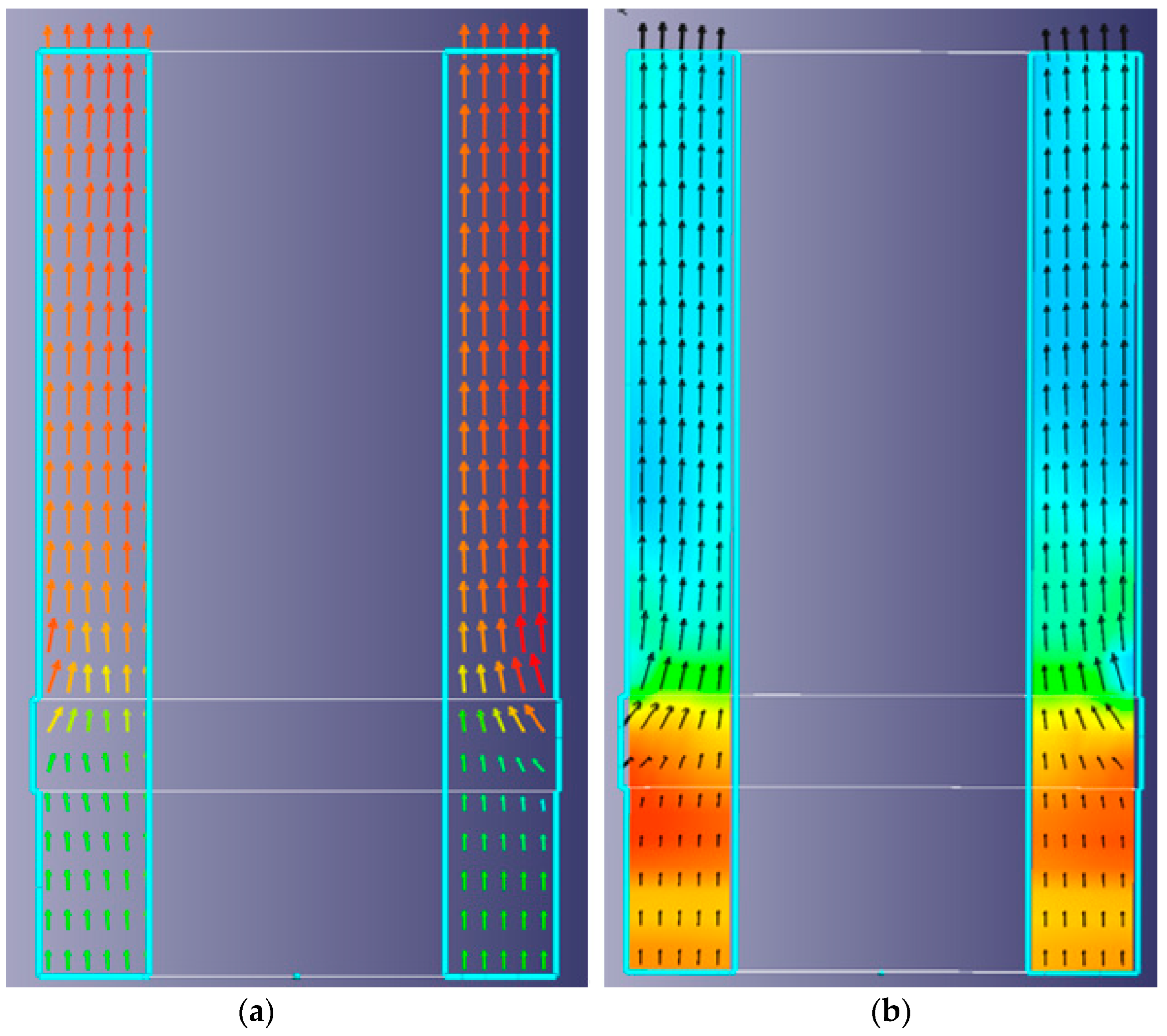
To reduce the unevenness of the air flow rate and increase the time of exposure of air to the grains, it is advisable to create a certain slight vacuum in the channel volume, under the influence of which air is sucked through holes or slots (slit perforation) in the outer and/or inner side surface of the channel. In this case (
Figure 2), the grains of the light fraction will not be able to fall to the lower output along the walls, as in a conventional channel.
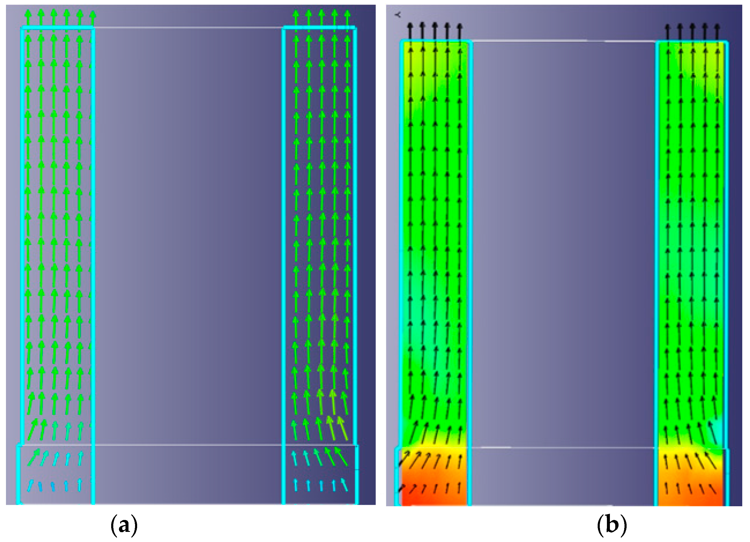
To provide the possibility of adjusting both the air velocity diagram and the air flow rate, it is advisable to use windows (annular) in the side walls with an adjustable window area.
It is advisable to use an annular channel of variable cross section (
Figure 3) to equalize the air velocity diagram in the grain input zone or to change its configuration so that the relative velocity gradient changes sign (the air velocity in the center is less than the velocity in the near-wall zone of the outer cylinder). This will also provide an increase in air velocity in the direction of travel in the lower zone.
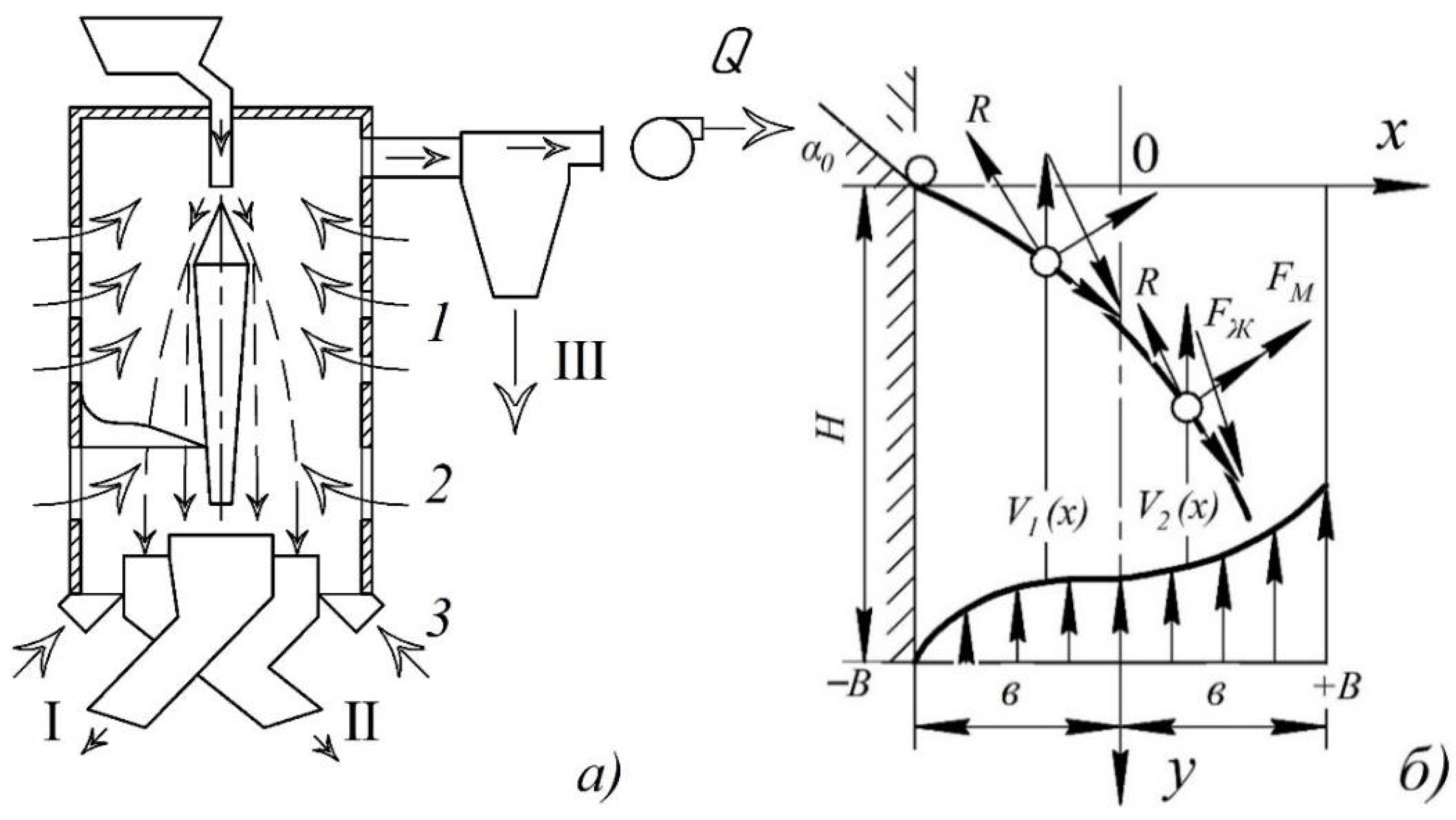
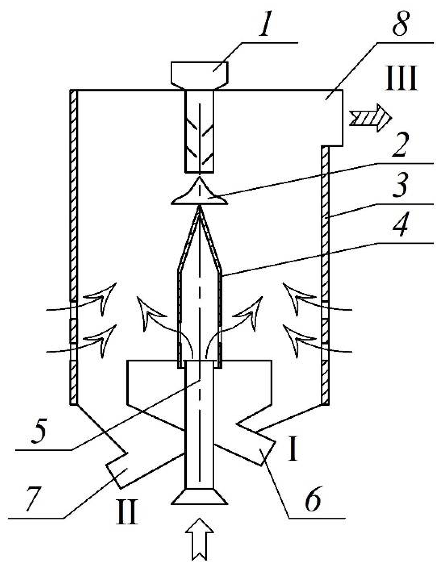
The scheme of a pneumatic gravitational separator with options of supply of external air is given in
Figure 4a. The calculated scheme of force interaction of grains with air flow operating on suction is given in
Figure 4b.
Without resorting to the technical details of the implementation of the directional field of air flow velocities, consider the option when an air flow is created in the middle (along the height) of the channel. This flow is characterized by an air speed distributed according to a power law at in the section (−b…0) and distributed according to the exponential law in the section (0…+b).
The speeds of air flow around the grain with the distribution of air velocities
and
in this form will be determined by the relations:
where
is the unit vector of the
x axis;
b is the distance from the inner wall to the channel axis;
x is the coordinate of the distance from the axis
x = 0 to the wall
x =
b.
Let us determine the value of air velocity gradients:
According to the presence of a flow gradient around a grain, a lateral force (Zhukovsky lift force) acts, which is proportional to the relative velocity of the air flow
incident on the grain and circulation
[
19,
28], i.e.,
where
r is the equivalent grain radius.
Let us assume that the grain, after descending from the feeding and distributing cone, can begin to rotate around its axis in the same direction as the air flow velocity vector. In this case, a lateral force [
28] (the Magnus effect) appears, the vector of which is directed normally to the relative velocity vector in the direction of increasing air velocity (increasing gradient).
This force is determined similarly to the Zhukovsky lift force [
26,
28], but the circulation depends on the grain rotation speed
. Thus, for the Magnus force, we have the relation:
Both forces and are directed in the direction, which contributes to the deviation of the grains to the outer wall of the channel; that is, it increases the deviation of the grain trajectories in the radial direction.
The force of aerodynamic resistance, through which the air flow acts on the grain, is known to be determined by the dependence (2).
As known [
21,
26,
28], the lines of action of the forces
,
and
pass through the center of mass of the grain. Then, the magnitude of the moment acting on the grain will be determined by the force of aerodynamic resistance and its shoulder relative to the center of mass. With a power-law distribution of air velocity along the
Ox axis, the value of the shoulder l can be taken as a variable according to the linear dependence [
1,
11,
28]:
Then, there will be a fair equation:
where
is the torque;
is the grain moment of inertia;
is the drag coefficient;
is the Reynods number, which characterizes the flow around the grain (in the turbulent mode
,
can be taken as 0.47).
The movement of a grain of mass
m in the form of a ball with an equivalent radius
r in an uneven air flow in the plane of a rectangular coordinate system is described by a system of differential equations, which in coordinate form take the form:
where
;
;
;
,
,
and
are projections of forces on the corresponding coordinate axes.
We define the projections of the acting forces modulo on the coordinate axes:
The projections of lateral forces are determined for each zone into which the channel is conditionally divided:
For
where
;
.
In a real pneumatic separation channel, there is a countercurrent movement of the flow of grain and air. That is, a certain volume of the channel is occupied by grain material. Therefore, the current speed of air flow around the grain will be increased relative to the empty channel. The value of the flow velocity in the intergranular space of the channel can be determined from the relationship:
where
is the air velocity in the channel without grain;
ε is the porosity in two-phase flow.
For the numerical solution of the resulting system of nonlinear equations, the initial conditions are set:
where
is the initial angle of input of grain material.
The solution of the system of Equations (14)–(23) with initial and limiting conditions was obtained in the MathCad-10 software by means of the trajectories of motion of the components of the grain material, the signs of separation of which are determined by the coefficient
and the mass
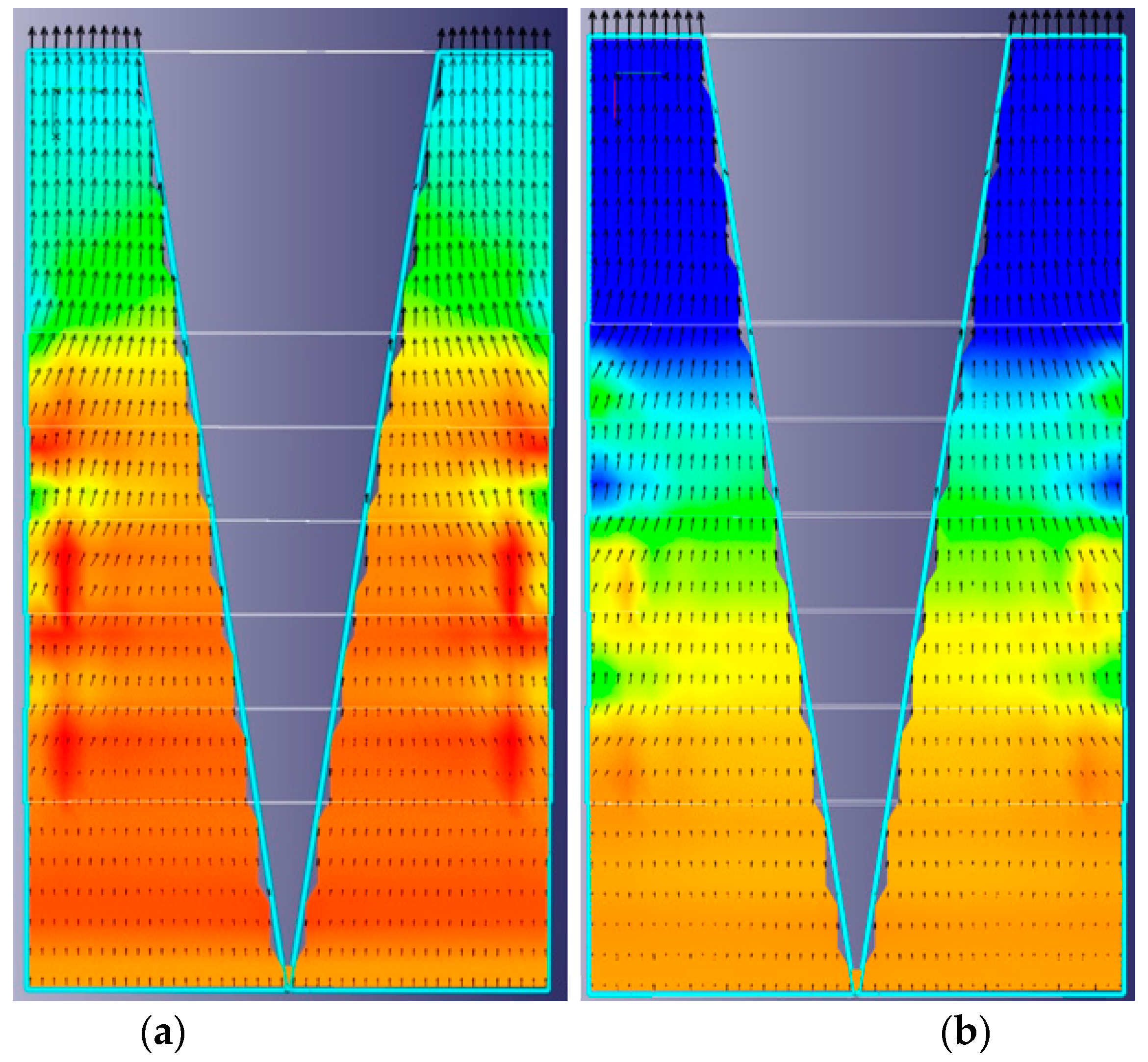
m. The trajectories of movement of the grain material components in a vertical channel with uneven air velocity are shown in
Figure 5, taking into account and neglecting the forces of the transverse action
.
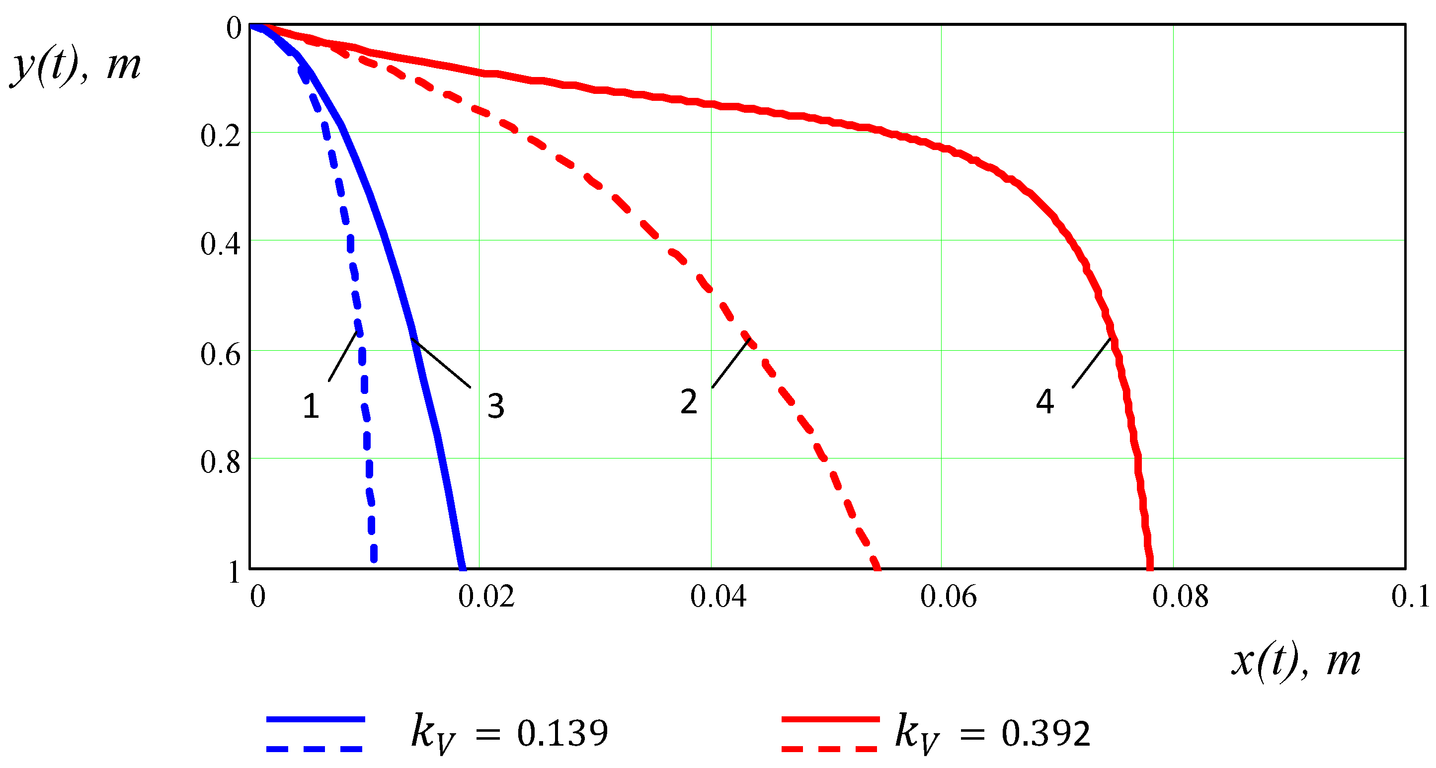
An analysis of the movement trajectories of grains of various weights or sizes shows that in the process of pneumatic gravity fractionation of grain material by the lower gathering, the main zone for separating grain material components is located at the point where the material is introduced into the flow. It is at this point that the splitting of the trajectories begins and the air flow is of the greatest importance. An increase in air velocity in this zone excludes the possibility of light fraction grains entering the lower gathering. To prevent the removal of grains of the middle fraction through the upper part of the channel, it is advisable to reduce the air velocity in the direction of its movement. Part of this fraction which entered the upper part of the channel with a decrease in air velocity falls out of the flow. Therefore, in the upper part of the channel, it is desirable to preserve the natural stepwise distribution of the flow velocity in the cross section.
Based on the analysis of the velocity field and preliminary studies [
30], proposed an improved scheme of a pneumatic gravity separator for separating grain material into three fractions according to aerodynamic characteristics.
The structural and technological scheme in the pneumatic separating channel is shown in
Figure 6.
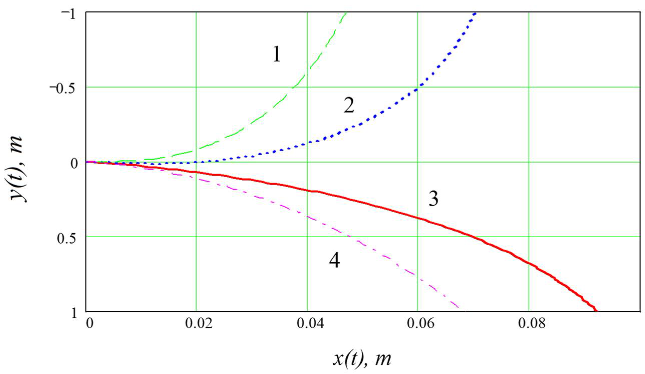
To calculate the trajectories of movement of grains in a pneumatic separating channel of a cross section that is variable in height, the distribution of air velocity in height is determined by the next equations.
For the bottom of the channel:
It has been established in the work that the change in the air velocity in a vertical channel in the direction of its movement according to the laws (27)–(29) makes it possible to significantly change the trajectory of grains with different values of
and increase the deviation of the trajectories ∆
x with a uniform distribution of air velocity. So, the data of the trajectory of the movement of grains are visualized in
Figure 7. Thus, changing the sign of the direction of the air velocity gradient in the cross section of the vertical channel allows you to increase the trajectory splitting factor (Δ
x) by 15–25% and the efficiency factor by 17–21%.
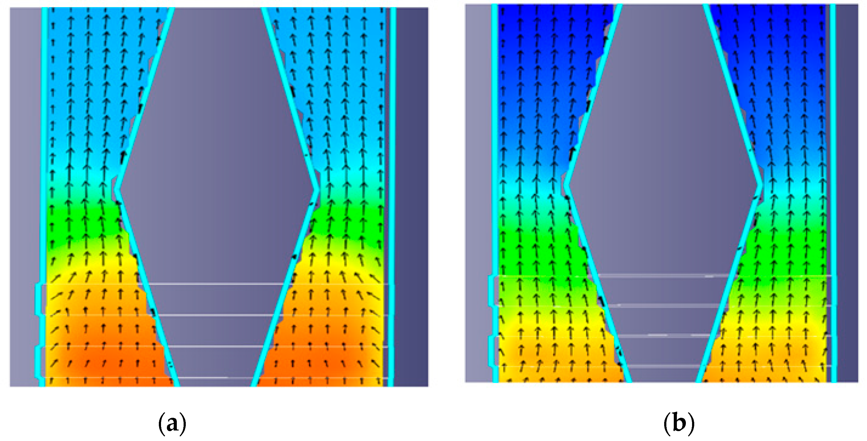
It was established that a change in the air velocity diagram can be realized by changing the geometric parameters of the channel. The scheme of the aspiration channel is shown in
Figure 4 (narrowing, expansion). As a result of the research, diagrams were obtained in the form of a velocity field (
Figure 8) of the air flow at various values of the suction air.


 ,
, 


