Article

Large Eddy Simulation of Conjugate Heat Transfer in a Ribbed Channel: Reynolds Number Effect

1
School of Mechanical Engineering, Kookmin University, Seoul 02707, Korea
2
School of Mechanical and Aerospace Engineering, Seoul National University, Seoul 08826, Korea
*
Author to whom correspondence should be addressed.
Processes 2022, 10(10), 1928; https://doi.org/10.3390/pr10101928
Submission received: 29 August 2022 / Revised: 13 September 2022 / Accepted: 20 September 2022 / Published: 23 September 2022

Abstract

:
Large eddy simulations were performed for the conjugate heat transfer in a ribbed channel with a geometry, that mimics the internal cooling passage of a gas turbine, using 566, 100, 10, and 1 as the solid and fluid thermal conductivity ratios (K*) and 30,000, 7000 (turbulent flow), and 1000 (laminar flow) as the Reynolds numbers. A fully coupled simulation was conducted using the immersed boundary method (IBM) and a dynamic sub-grid-scale (SGS) model. In pure convection, a decrease in the Reynolds number from 30,000 to 7000 increased the heat transfer on the channel wall by 5% but decreased that on the rib by 20%. When K* > 10, the Reynolds number effect is stronger in the rib than in the wall. In the laminar flow, the effect of conduction appears at a low K*, and the heat transfer promotion is poor in the typical ribbed channel geometry. In the turbulent flow, if K* ≥ 100, then a heat transfer promotion is expected in the ribbed channel even at a low Reynolds number. For K* < 10, the thermal performance in the turbulent flow is worse than that in the laminar flow, and thus, no rib effect is expected.

1. Introduction

A gas turbine is mostly used as an aircraft engine or as a prime mover for gas-fired power generation. The power output and cycle efficiency of a gas turbine can be improved by increasing the turbine inlet temperature. The currently used gas-turbine inlet temperature (1700 °C) is higher than the permissible limit of the blade material (1000 °C). Therefore, the turbine blade has a cooling passage inside as shown in Figure 1a and is cooled by extracting a part of the compressor air [1]. As shown in Figure 1a, a turbulator—such as a rib—is installed in the cooling passage of the turbine to increase the convective heat transfer rate and surface areas. The goal of these internal cooling passages is to achieve optimal thermal protection with minimal pressure drop penalties [2].
To achieve the above goals, various geometrical parameters have been studied. Since a rib promotes heat transfer by inducing various types of secondary flows depending on separation–reattachment and the geometry, detailed flow and heat transfer distributions are required to elucidate the underlying mechanisms [3]. Computational fluid dynamics (CFD) can provide this information and save the time and cost involved in fabricating internal cooling passages with various geometries [4].
The most economical CFD is the Reynolds-averaged Navier–Stokes simulation (RANS), which has been widely applied to ribbed channels [5]. Acharya et al. [6] performed RANS using nonlinear and standard k-e models. Both models adequately predicted the size of the recirculation region, but underpredicted the local heat transfer and Reynolds stresses. Ooi et al. [7] applied the v2-f turbulence model to obtain an average heat transfer coefficient close to that of the experiment in the channel wall. However, the heat transfer peak before the rib could not be predicted. To solve these problems, direct numerical simulation (DNS) or large eddy simulation (LES), which require more time and costs than does the RANS, are being tried [5].
Murata and Mochizuki [8] conducted LESs to investigate the difference in the mechanism of promoting heat transfer between laminar and turbulent flows. However, they conducted the simulations at a Reynolds number that was 10 times lower than the internal cooling passage of the actual gas turbine, and thus, a direct comparison with the experimental results was difficult. Ahn et al. [9] and Sewall et al. [10] performed LESs on a Reynolds number similar to that of a real gas turbine blade to obtain a local Nusselt number distribution close to that of the experiment. In particular, they successfully predicted the local heat transfer peak in front of the rib, which was not well predicted by the RANS.
In a ribbed channel, the rib also serves as a fin while promoting heat transfer in the channel wall [11]. Most of the experimental studies on ribbed channels focus on the heat transfer of the channel wall [3,12]. CFD provides information on the heat transfer coefficient of the rib. However, in order to understand the fin performance, the heat transfer coefficient as well as the heat conduction of the rib itself must be known. Iaccarino et al. [13] reported the results of conjugate heat transfer, including heat conduction of ribs, obtained using the RANS. Although they reported the effect of conjugate heat transfer, at the time of publication, results of the rib conjugate heat transfer experiments were not obtained, and thus, a detailed comparison with the experimental data was not possible.
About 10 years later, Cukurel and Arts [14,15] published experimental results on the conjugate heat transfer of ribs. In the experiment, they considered the heat conduction of the channel wall, which was not considered by Iaccarino et al. [13]. However, the wall thickness was equal to the height of the rib (=e). This was much thinner than the actual thickness of a gas turbine blade of 2 to 10 e [16]. In addition, the blockage ratio (=e/H) was also 0.3, which was somewhat larger than the typical value of 0.1 of an actual gas turbine [16]. Scholl et al. [17,18] performed LESs under the same conditions as those reported in [14,15]. They used a separate solver for the simulation of fluid and solid, and the LES did not completely couple the fluid and solid domains to save computation time.
By implementing the IBM (immersed-boundary method), it is possible to analyze the fluid and solid simultaneously in the unitary computational domain, so that fully coupled conjugate heat transfer simulation can be performed [19]. Recently, Oh et al. [20] and Ahn et al. [21] applied this method to perform fully coupled LESs for the conjugate heat transfer of a ribbed channel. Oh et al. [20] simulated the same conditions as those of [14,15]. In [21], the blockage ratio was set to 0.1, and the wall thickness was set to 3e in consideration of the actual gas turbine geometry (see Figure 1b).
The local heat transfer distributions of [14,15,21] were generally similar. The difference is that when the blockage ratio is 0.1 [21], the difference between the conducting wall and the isothermal wall is slightly reduced compared with that when the blockage ratio is 0.3 [14,15]. Moreover, the heat transfer in the channel wall is predicted to be slightly larger. In both the datasets, the effect of conduction was concentrated on the rib, indicating that including the thickness of the channel wall in the calculation area would not have a significant effect.
In the above data [14,15,21], the thermal conductivity ratio between the solid and the fluid was 566, similar to that of the gas turbine material. This ratio was very large, and the effect of conjugate heat transfer was less than 10%. This was also the case in other recently published studies dealing with the conjugate heat transfer of ribbed channels [22,23]. However, additive manufacturing has been recently applied to gas turbine blades, and as a result, changes have occurred in the material [24]. Moreover, cooling fluids other than air, such as steam, are also being considered while researching new cycles [25]. In these cases, the conductivity ratio can be less than 566. Ahn et al. [26] performed LESs for thermal conductivity ratios (K*) of 566, 100, 10, and 1, and presented conjugate heat transfer characteristics according to these thermal conductivity ratios.
Ahn et al. [26] showed that the conjugate effect was concentrated on the rib until K* = 100, but the conduction of the channel wall became important at K* = 1 and 10. The factor that determines the conjugate heat transfer characteristics along with the thermal conductivity ratio is the heat transfer coefficient on the fluid side. The heat transfer coefficient on the fluid side is determined by the thermal conductivity of the fluid and the Reynolds number. In particular, the influence of the wall thermal boundary condition is significant at a low Reynolds number, where the contribution of diffusion is greater than that of the turbulent heat flux [27]. In gas turbines, the Reynolds number decreases as a more sophisticated structure is prepared with additive manufacturing [28], making it necessary to review the thermal boundary condition.
In order to simulate the Reynolds number, the effect of the Reynolds number reported to date [8,29,30,31] was reviewed. As the Reynolds number increases, the heat transfer performance gradually decreases [29], but the change in the flow structure [30] or local heat transfer distribution [31] is not significant above (Reynolds number) 10,000. In the laminar [8] or turbulent flow [8,30] smaller than the Reynolds number of 10,000, differences in flow structure or local heat transfer distribution are observed. Based on these data, in this study, three Reynolds numbers, i.e., 1000 (laminar flow), 7000 (turbulent flow less than Reynolds number 10,000), and 30,000 (representative values of gas turbines), were analyzed.
Simulations were performed for a total of 15 cases of K* = 1, 10, 100, 566, and the isothermal conditions at the aforementioned three Reynolds numbers. In this paper, heat transfer according to Reynolds number in pure convection is first compared. Next, the conductivity ratio showing the conjugate heat transfer effect according to the Reynolds number is examined. Third, the turbulent heat transfer statistics for the four thermal conductivity ratios are compared according to the Reynolds number in the turbulent flow. Finally, the rib fin and thermal performances of the ribbed channel are analyzed.

2. Numerical Methods and Code Validation

2.1. Numerical Methods

The computational domain considered in the present study is illustrated in Figure 1b. Here, ribs of a square cross-section, each with a height equal to 0.1 of the channel height (=H), are installed at intervals of 10 e on both sides of the channel. The computational domain, holding three periods in the x direction, and the domain, made up of one period, were compared, and the same time-averaged result was secured. Finally, the domain was set to have one period as presented in Figure 1b. For the laminar flow, a two-dimensional simulation was performed. In the turbulence simulation, the spanwise domain was set to 2.5 π e, which showed zero fall-off in the two-point correlation in the smooth channel simulation [9,11]. The solid wall thickness was set to 3 e, in accordance with the actual gas turbine blade [16]; this value corresponds to 30% of the channel height [21,26].
For the boundary conditions, periodic conditions are imposed on the main flow direction (x) and spanwise direction (z). Usually, five or more ribs are reportedly installed in the cooling passage of a gas turbine in the flow direction [16], and the developing effect becomes negligible from the third rib [32]. In the wall normal direction (y), no slip condition and constant temperature condition are appointed on the top and bottom surfaces of the computational domain.
The grid system was composed of 128 × 256 × 48 notes in the streamwise direction (x), wall normal direction (y), and spanwise direction (z), respectively (Figure 1b). A non-uniform mesh was adopted in the x and y coordinates, while a uniform mesh was placed in the z direction. This is comparable to the resolution derived by Tafti [33] for the grid independent solution obtained via LESs of a ribbed duct.
The governing equations considered in this study are the following incompressible Navier–Stokes and energy equations (Equations (1)–(3)):
u ¯ i x i m s = 0
u ¯ i t + u ¯ i u ¯ j x j = d p ¯ d x i + 1 Re   2 u ¯ i x j x j + τ i j x j + f i
  θ ¯ t + ω   x j ( u ¯ j θ ¯ ) = C * K * Re   Pr 2 θ ¯ x j x j + q j x j + ξ
In this study, a finite volume solver [34] was employed to solve the above equations. The pressure–velocity coupling is a fractional step method. All spatial discretizations were carried out by the central difference method with second-order accuracy. Time integration was performed using a semi-implicit method that combines the Crank–Nicolson method and the third-order Runge–Kutta method.
This code has been revised to treat solids in the flow field as the immersed boundary method (IBM) [35]. ms in Equation (1) and fi in Equation (2) are mass source and momentum forcing that satisfy the no slip condition on a solid surface, respectively. Using the IBM, the code that could contain solids was later revised to solve for convective heat transfer as well [36].
In this study, the revised [19] code was used to analyze the conjugate heat transfer. In Equation (3), C* and K* are the heat capacity ratio and thermal conductivity ratio of the solid and fluid, respectively; ω is a convection revising term that is 0 in the cell containing the solid–fluid interface and 1 for other cells to account for the conduction between the solid and the fluid. In Equation (3), ξ was added to secure the second-order accuracy in the cell containing the boundary [19].
Turbulent flow was simulated using the LES. In Equations (1)–(3), τij and qj are the sub-grid scale (SGS) stress and heat flux, respectively; τij is determined as a dynamic SGS model using scale correlation by framing a test filter around the cell [37,38]; and qj is also determined dynamically like τij to secure better results in problems where velocity and temperature are dissimilar [39]. The simulation was carried out for 10,000 time steps to reach a fully developed flow. After the initial steps, an additional 10,000 time steps (t Ub/Dh = 5) were performed to obtain the statistics.

2.2. Code Validation

For the validation of the simulation code, the time-averaged flow field and temperature field were compared with those reported in previous studies as shown in Table 1.
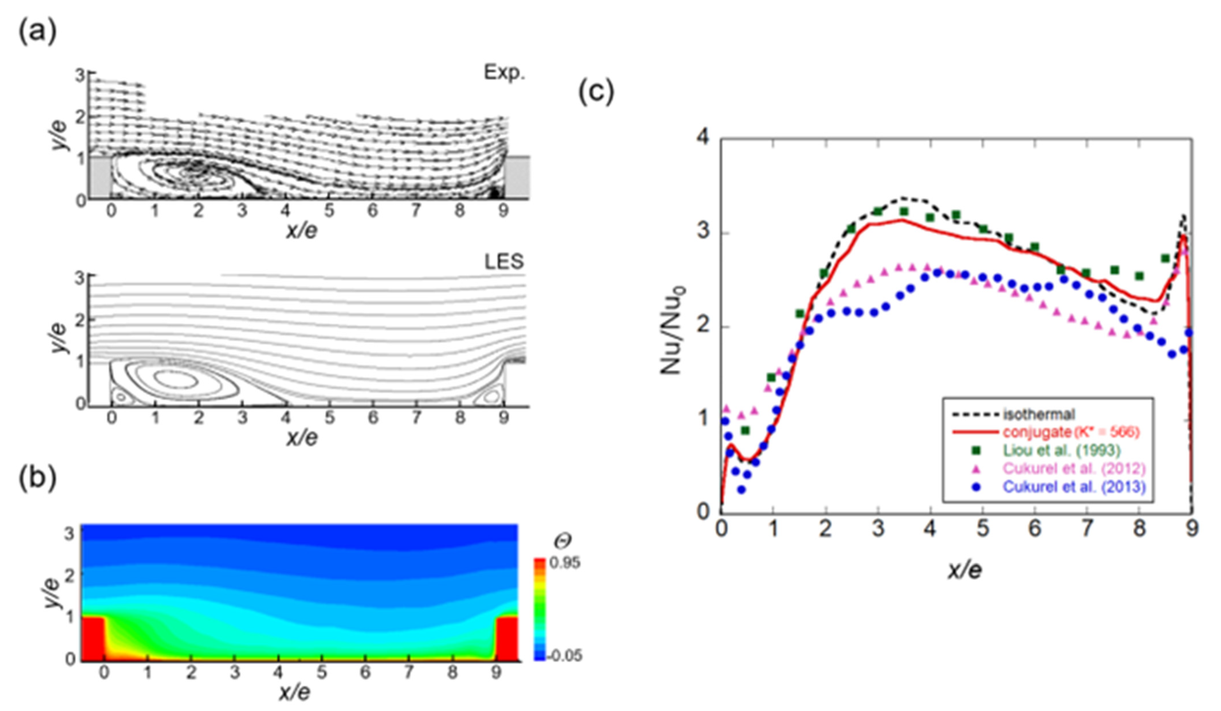
Figure 2a compares the time-averaged flow fields. The streamlines obtained by the LESs are in good agreement with the particle image velocimetry (PIV) measurement data [41]. Figure 2b shows the time-averaged temperature field, indicating the formation of a high-temperature region behind the rib because of an inactive heat transfer.
Figure 2c presents a comparison of the Nusselt number ratio at the channel wall between the ribs. The results obtained for both the isothermal (black dashed line) and K* = 566 (red line) conditions agree well with those of Liou et al. [40] with the same blockage ratio. The inter-rib heat transfer under isothermal conditions with conjugate K* = 566 is similar. At K* = 566, the heat transfer coefficient due to the conduction effect is less than that due to the isothermal condition at 2 < x/e < 5 and greater than that due to the downstream isothermal condition.
A similar trend was observed when comparing the experimental results of pure convection [14] (pink triangle) and conjugate heat transfer [15] (blue circle). The data of [14,15] have a Nusselt number ratio that is up to 30% smaller than the rest of the data near the reattachment point. The difference seems to be due to the difference in the blockage ratio. It was confirmed that the flow pattern as well as the local heat transfer, including the conduction effect, were properly predicted.

3. Results and Discussion

3.1. Effect of Reynolds Number on the Isothermal Ribbed Channel

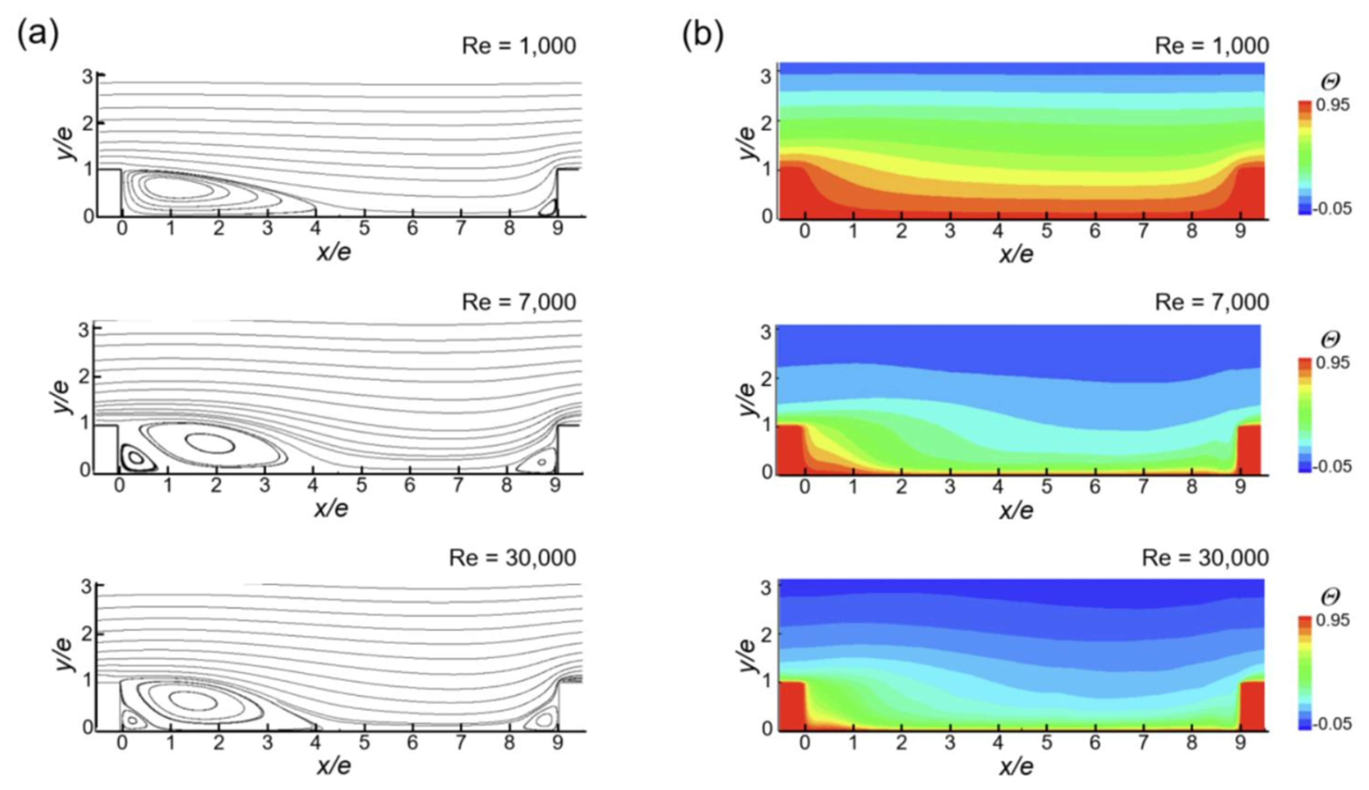
Figure 3 shows the time-averaged flow and temperature fields according to the Reynolds number in pure convection. For the three Reynolds numbers, flow separation occurs after the rib, and a corner vortex exists before the rib. The reattachment points are all around x/e = 5.5, but slightly upstream for Re = 30,000. In the turbulent flow (Re = 7000 and 30,000), a secondary vortex occurs between the separation bubble and the downstream corner. In the laminar flow, no flow separation is observed at the upstream edge of the rib, whereas such a separation is evident in the turbulent flow case.
In the temperature fields (Figure 3b) observed for all the three cases, the thermal boundary layer is thick at 0 < x/e < 4 with a recirculation bubble and the thinnest at 5 < x/e < 6 near the reattachment point. As the Reynolds number increases, mixing with the main flow is observed, the thermal boundary layer becomes thinner, and the low-temperature (blue) region approaches the wall. In the laminar flow (Re = 1000), the isotherm spacing is relatively uniform, whereas that in the turbulent flow is excessively narrow at the high temperature side (red color). In the turbulent flow, the dimensionless temperature of the main flow (y/e = 3) is lowered at Re = 30,000 than at Re = 7000, and the isotherm is narrowed at 0 < x/e < 1.
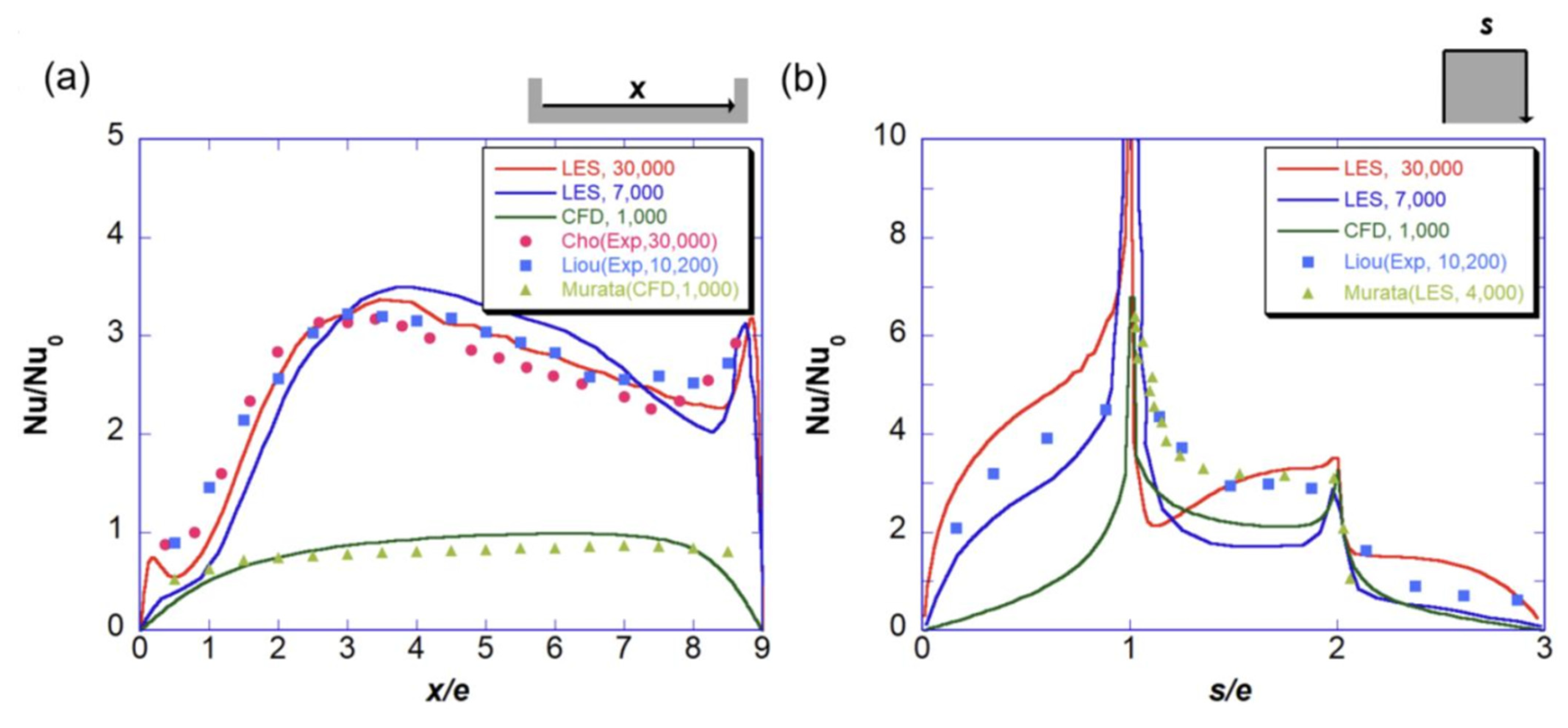
Figure 4 compares the local wall heat transfer distribution according to the Reynolds number for pure convection. The local Nusselt number is expressed as a ratio with Nu0, which represents the Nusselt number in the absence of ribs. In the channel wall between the ribs (Figure 4a), the laminar flow (green line in Figure 4a) shows a value less than 1 in the entire section. The data reported in [8] (green triangles in Figure 4a) and the difference occurring near the rib can be considered as a three-dimensional effect based on the observations reported in [8].
In the turbulent flow (red and blue lines in Figure 4a), the heat transfer is promoted two to three times in the inter-rib wall. The Nusselt number ratio at Re = 30,000 (red line) is greater than that at Re = 7000 (blue line) at 0 < x/e < 3, where the recirculation flow occurs. In contrast, at 3 < x/e < 7 near the reattachment point, the blue line lies above the red line. At 3 < x/e < 7, the experimental value obtained at Re = 10,200 showed a higher Nusselt number ratio than that at Re = 30,000, consistent with the LES result. At 0 < x/e < 1 where the secondary vortex exists, a local peak is observed in the red line, but not in the blue line. This is because mixing with the main flow is more active when Re = 30,000, which can also be confirmed in the temperature field shown in Figure 3b.
The difference in the Nusselt number ratio between the laminar and turbulent flows in the rib is less than that in the channel wall (Figure 4b). In both the laminar and turbulent flows, the most active heat transfer is observed at the upstream edge of the rib. For the turbulent flow (red and blue lines in Figure 4b), on the windward surface of the rib (0 < s/e < 1), the Nusselt number profile is upwardly convex at 0 < s/e < 0.5 due to the impinging effect of the main flow reattached to the wall [9].

3.2. Time-Averaged Thermal Fields in the Conducting Ribbed Channel

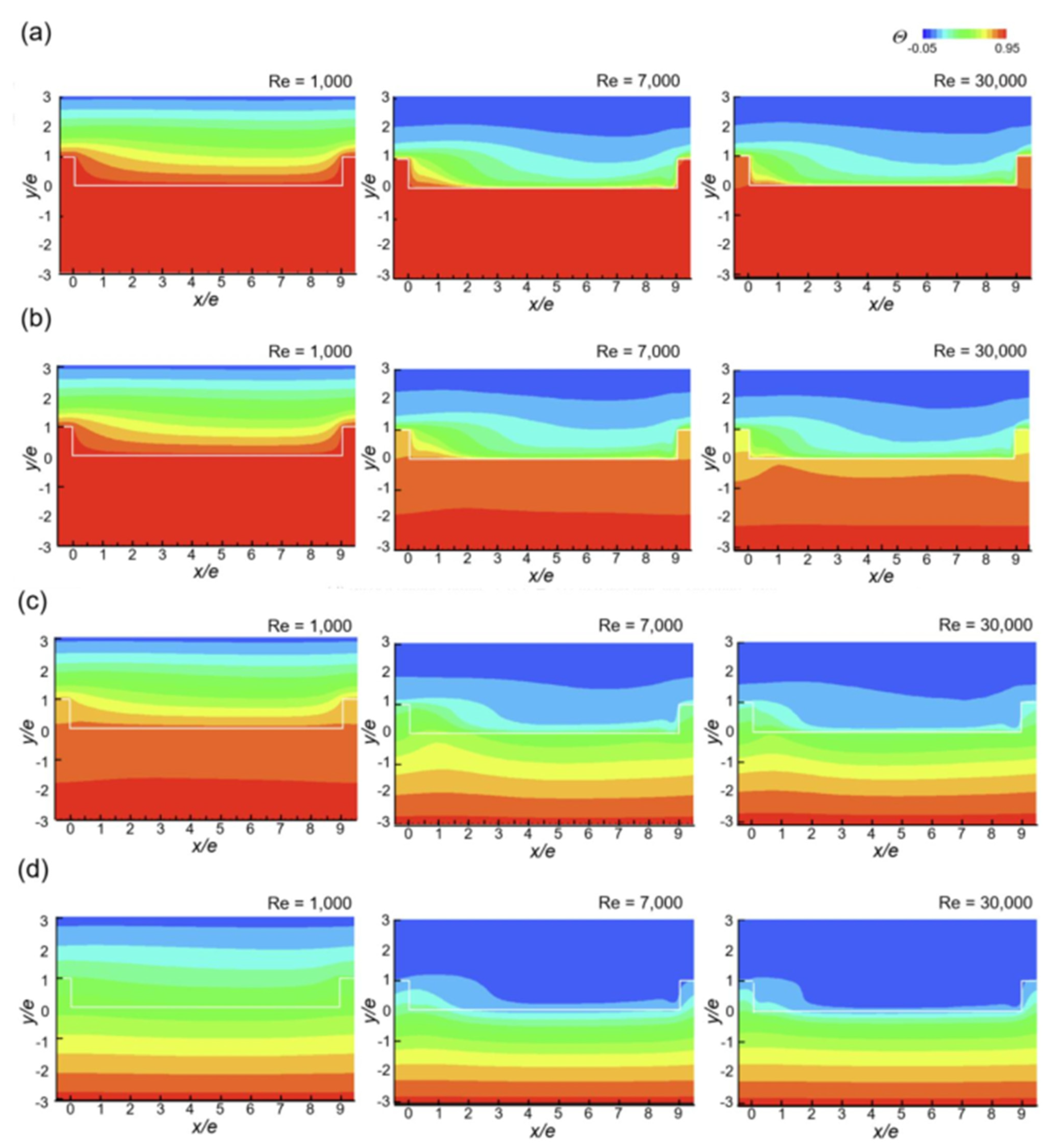
At K* = 566 (Figure 5a), most of the thermal resistance occurs on the fluid side at all the Reynolds numbers. Since the conjugate effect is not large, the temperature of the solid region is displayed in red. At Re = 30,000, the rib is red orange, and the conjugate effect is limited to the rib.
In the case of laminar flow (Re = 1000) at K* = 100 (Figure 5b), the conduction effect is still negligible, and thus, the solid region remains red. In the turbulent flow (Re = 30,000 and 7000), the conduction effect appears around the rib. Because the fluid region has a higher thermal resistance than does the solid region, the solid region appears red or orange. Unlike the case of K* = 566, the conduction effect appears not only in the rib but also in the channel wall, and the isotherm goes down to y/e = −2.
At K* = 10 (Figure 5c), the conjugate effect begins to appear even in the laminar flow, but most of the thermal resistance still occurs in the fluid region. In the turbulent flow, as the conduction thermal resistance becomes larger than the convection resistance, the temperature change within the solid becomes larger than the temperature difference between the surface of the solid and the fluid, making lumped capacitance analysis impossible.
When K* = 1 (Figure 5d), the thermal resistance of the conduction and the convection becomes similar in the laminar flow. In the turbulent flow, the thermal resistance of the solids is much greater than that of the fluids, and most of the fluid region appears blue. Overall, in the turbulent flow, the conjugate heat transfer effect is large, but the effect of Reynolds number is not clearly detected in the temperature field.
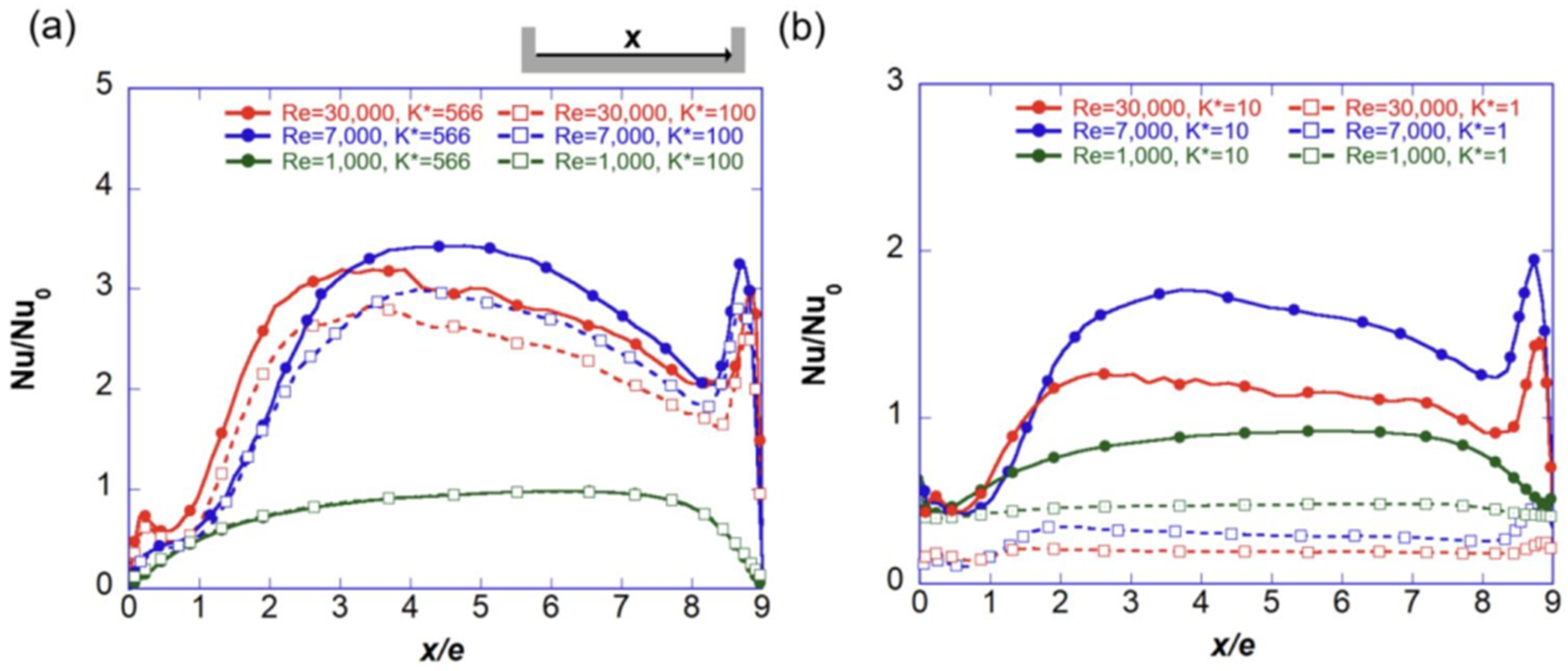
The Reynolds number effect in turbulence can be clearly observed by comparing the local heat transfer distributions (Figure 6 and Figure 7). When K* is large in the inter-rib wall (Figure 6a), the Nusselt number ratio peaks upstream at Re = 30,000 (red) than at Re = 7000 (blue), and the corresponding peak value at Re = 7000 is approximately 5% smaller. Even when K* = 100 (dashed lines in Figure 6a), the same trend is observed, but as the conduction effect becomes stronger, the heat transfer coefficient decreases in the region 3 < x/e < 7. In the laminar flow, the conduction effect does not appear above K* = 100.
When K* < 10 (Figure 6b), the heat transfer coefficient is significantly reduced because of the conduction effect. The Reynolds number effect increases in the turbulence. The heat transfer coefficient ratio is larger at Re = 7000 than at Re = 30,000 by 30%. When K* < 10, the effect of the thermal conductivity ratio is evident even in the laminar flow. When K* = 1 in the laminar flow, the heat transfer coefficient ratio decreases to half of that at K* = 10.
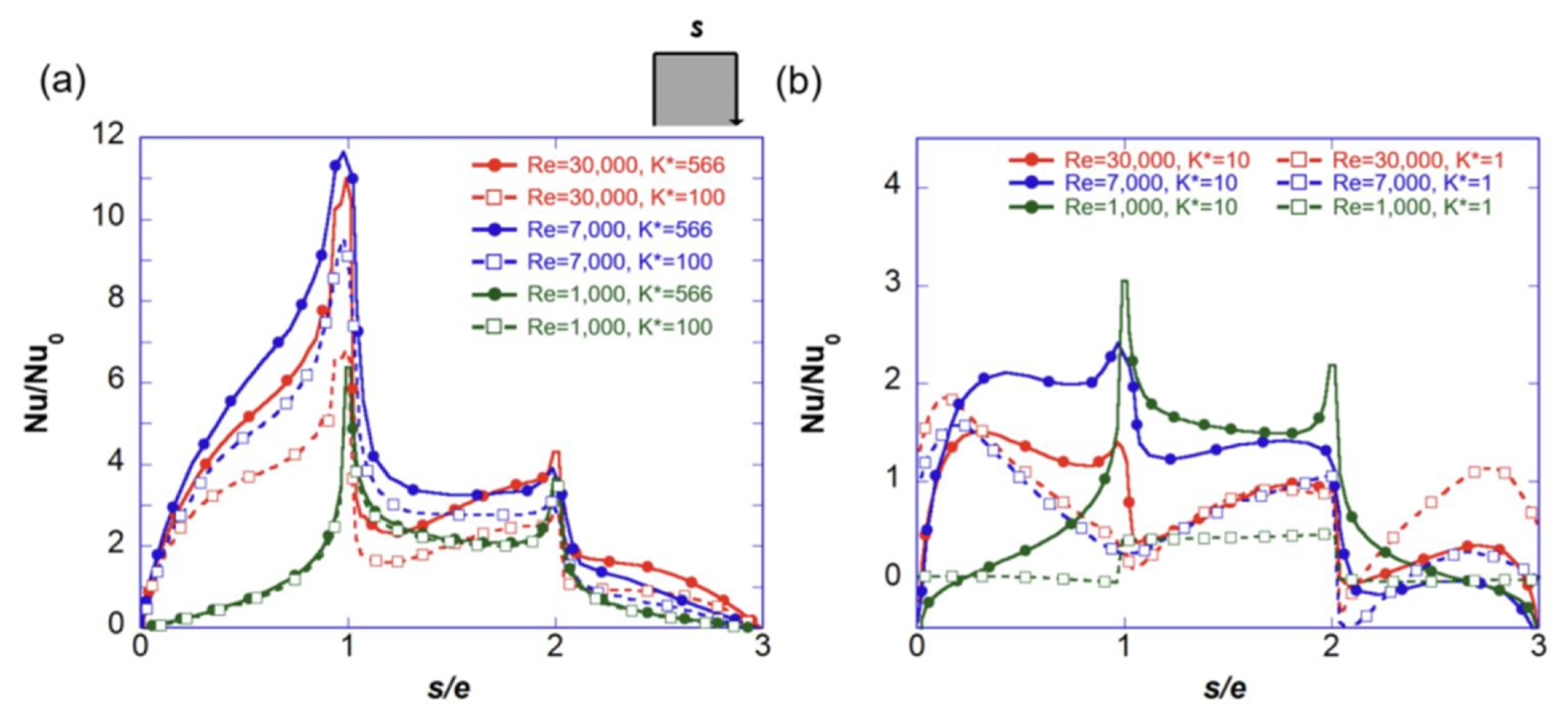
In the isothermal rib, the heat transfer at Re = 7000 is less than that at Re = 30,000 (Figure 4), but vice versa in the conducting wall. As shown in Figure 5a,b, the conjugate heat transfer effect at the rib is stronger at a high Reynolds number, so when K* > 100 (Figure 7a), the heat transfer in the windward and top surfaces of the rib (0 < s/e < 2) at Re = 7000 is greater than at Re =30,000. In the case of the inter-rib channel wall (Figure 6a), the conjugate heat transfer effect does not appear in the laminar flow on the rib surface.
Up to K* = 10, the Reynolds number effect appears in the K* = 100 subphase on the conjugate heat transfer of the rib (see Figure 7b). In the front and top surfaces, the Nusselt number ratio at Re = 30,000 is larger than at Re = 7000. However, this effect disappears when K* = 1. Below K* = 10, the influence of the K* appears even in the laminar flow. When the thermal conductivity of a solid decreases, the Nusselt number ratio also decreases significantly.

3.3. Turbulent Heat Transfer Statistics

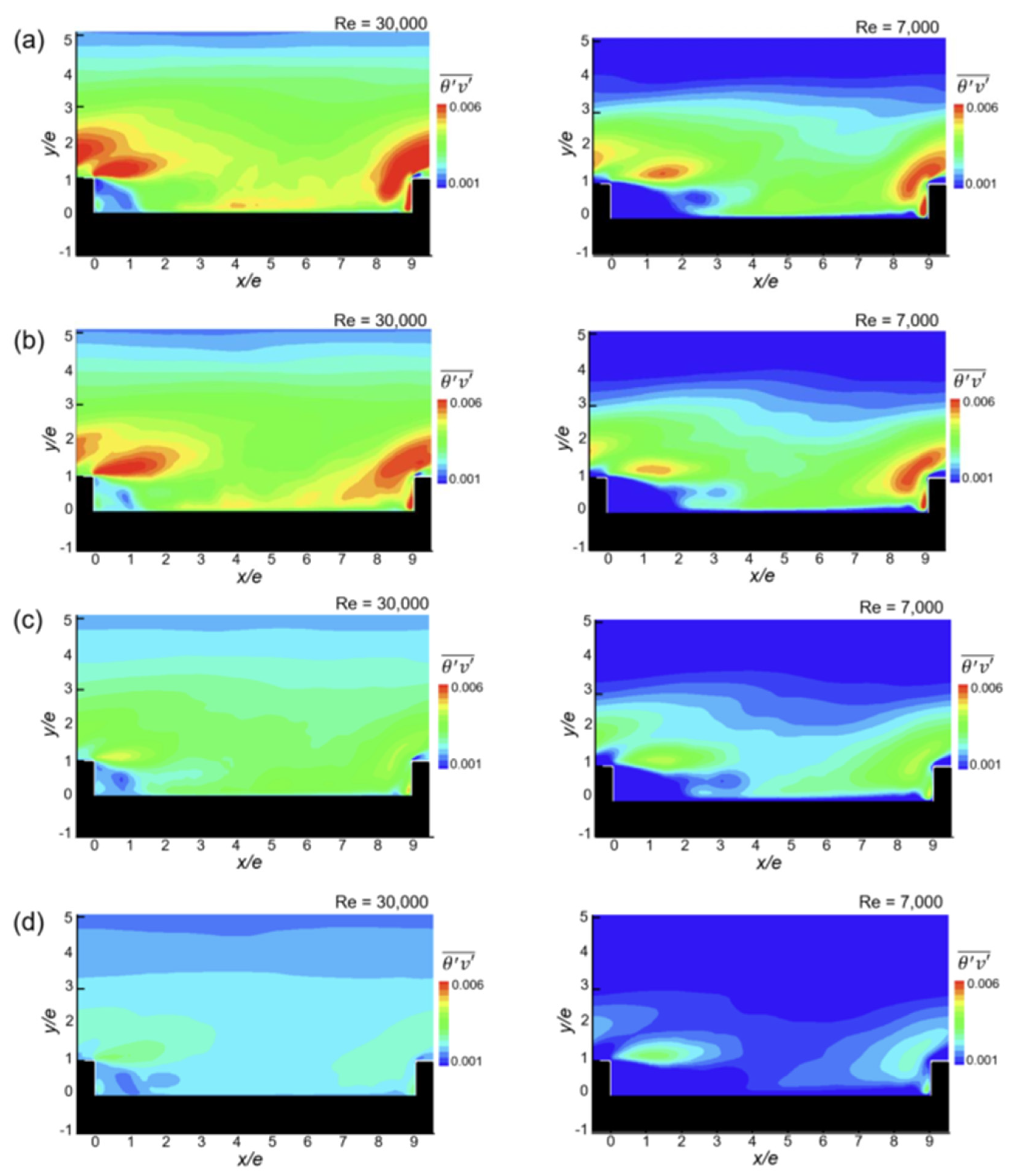
The contour of the turbulent heat flux is presented in Figure 8. Overall, as the conductivity ratio decreases (Figure 8a–d), the turbulent heat flux decreases as well. Qualitatively, the distribution at Re = 7000 is similar to that at Re = 30,000; however, the quantitative value is small. In all the contours shown in Figure 8, a region with large turbulent heat flux occurs along the shear layer at the downstream edge of the rib (x/e = 0, y/e = 1). When the Reynolds number decreases to 7000, this region shifts slightly downstream.
The turbulent heat flux near the wall is closely related to the heat transfer [27]. A region of low turbulent heat flux exists near the wall at 0 < x/e < 2, where the recirculation flow exists, and at Re = 7000, this region extends downstream. When K* is large (Figure 8a,b), a region with a large turbulent heat flux is observed on the channel wall, where 4 < x/e < 6, at Re = 30,000. These regions are not clearly observed when K* is small or Re = 7000.
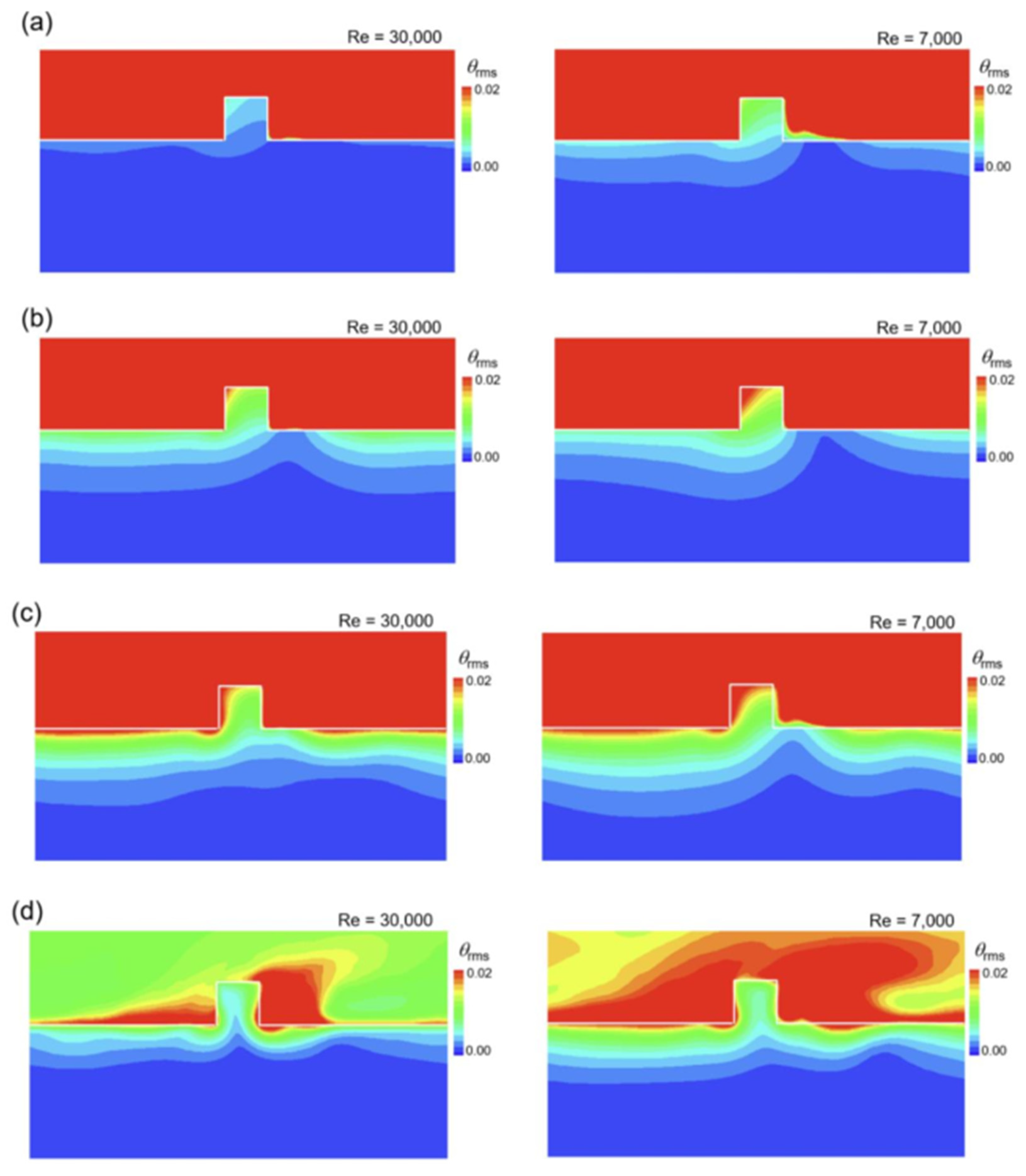
Figure 9 compares the temperature fluctuations according to the Reynolds number and thermal conductivity ratio. Except when K* = 1, most temperature fluctuations occur in the fluid region, and the fluid region appears in red. The situation at Re = 7000 is similar to that at Re = 30,000, but the fluctuations in the solid are slightly larger. As K* decreases or Re decreases, the temperature fluctuations inside the solid increase, so a fully coupled simulation that analyzes the conduction and flow in the solid in real time has more justification.
When K* is large (Figure 9a,b), the temperature fluctuation in the solid is the largest at the upstream edge of the rib. In the vicinity of the channel wall, the heat transfer is not active in the recirculation region behind the rib, so the temperature fluctuation is small, and the contour appears to rise toward the channel wall. When K* becomes 10 (Figure 9c), the temperature fluctuation increases near the upstream corner. In the case of K* = 1 (Figure 9d), the temperature fluctuations increase in the vicinity of the downstream corner, while they decrease at the rib, and the internal isotherm appears to rise toward the rib.

3.4. Thermal Performance

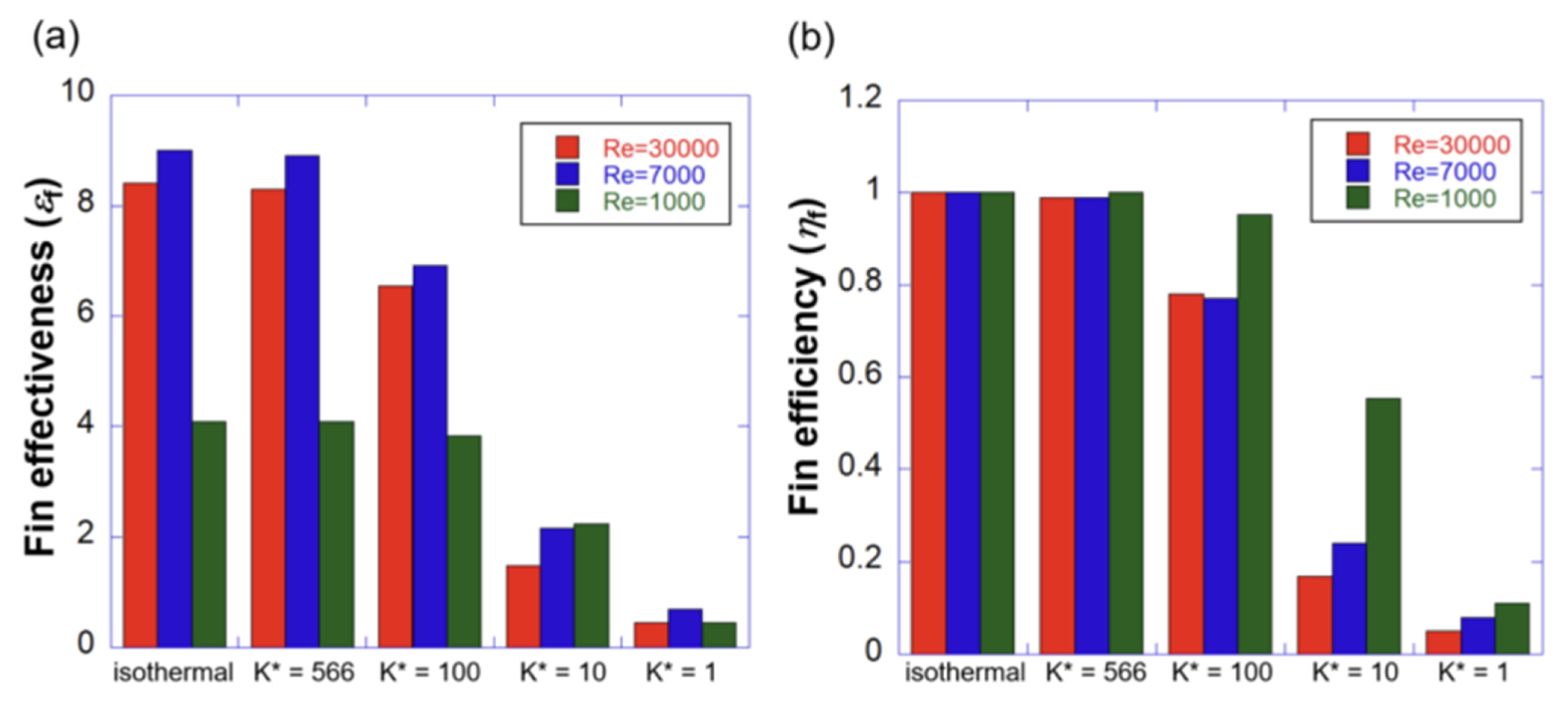
The rib acts as a fin to expand the heat transfer area while promoting the heat transfer of the channel wall as a turbulent promoter. Figure 10 shows the fin performance under the simulated conditions. Fin effectiveness (εf) is the ratio of heat transfer rate between the bare base and the fin, and is defined using the following equation [42]. Usually, it should be 2 or more.
ε f = q r i b , c o n j h c o n v A c , b ( T w T b ) .
When K* is more than 100, the fin effectiveness is much higher than 2 in all the three Reynolds numbers cases (see Figure 10a). At K* = 10, the effectiveness becomes smaller than 2, and the gain obtained through the fin is greatly reduced. At K* = 1, the rib acts as a thermal resistance, and the effectiveness becomes less than 1.
When K* is more than 100, the turbulent flow (red and blue bars) is twice as effective as the laminar flow (green bars). In the turbulent flow, Re = 7000 is more effective than Re = 30,000 by 5%. When K* becomes smaller than 10, the relative difference between the effectiveness of Re = 30,000 and Re = 7000 increases. At K* = 10, the fin effectiveness is lower in the turbulent flow than in the laminar flow.
Fin efficiency, which is another indicator of fin performance, is the ratio of the heat transfer rate of the fin to the actual heat transfer rate under isothermal conditions, and is defined as follows [42]:
η f = q f q m a x = q r i b , c o n j h c o n v A r i b ( T w T b ) .
At K* = 566, the efficiency is nearly 1 for all the Reynolds numbers (see Figure 10b). When K* = 100, the efficiency is still close to 1 in the laminar flow, but decreases to less than 0.8 in the turbulent flow. When K* = 10, the efficiency in the laminar flow is maintained over 0.5, but it decreases to 0.2 in the turbulent flow. At K* = 1, the efficiency becomes less than 0.1 at all the Reynolds numbers.
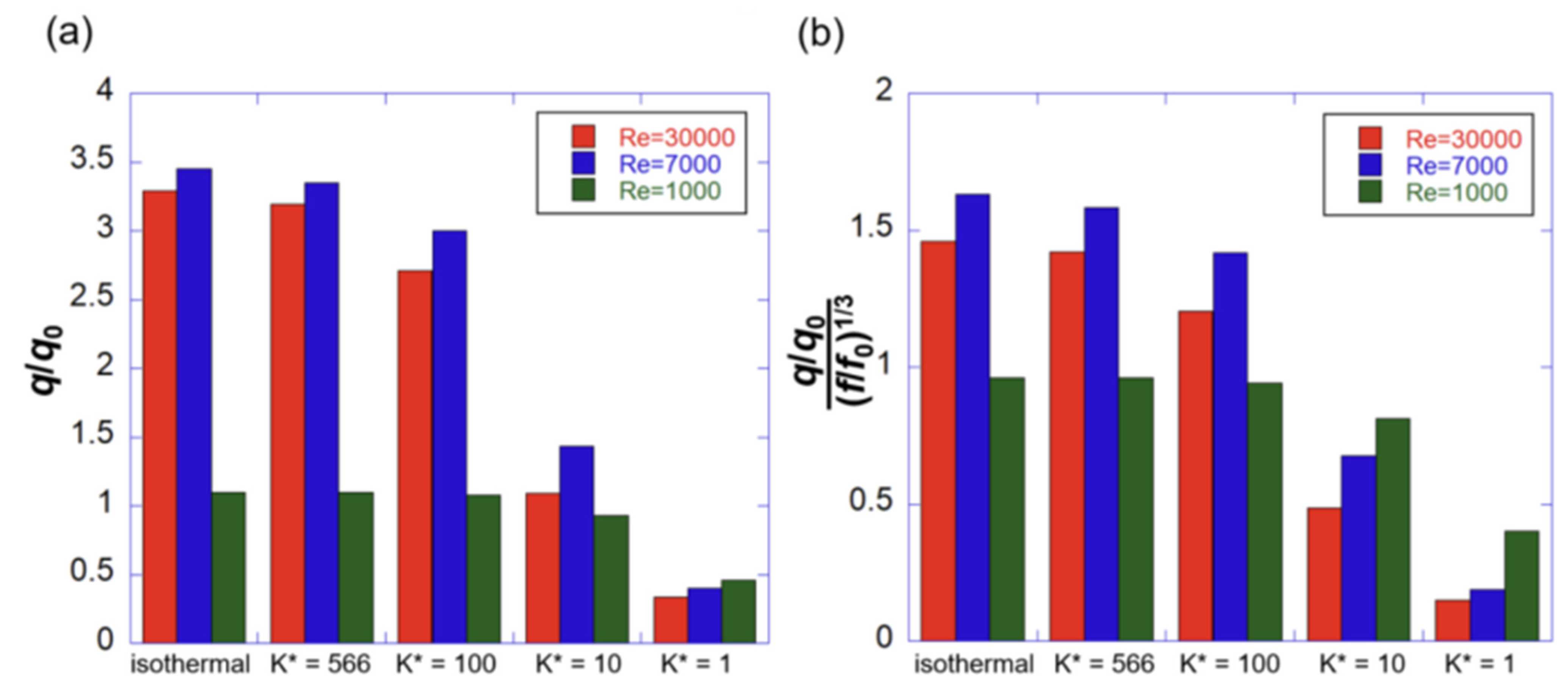
The effect of promoting heat transfer via the rib is shown in Figure 11a. When K* is over 100, the ribbed channel promotes heat transfer 2.5 times more than the smooth isothermal channel in the turbulent flow (red and blue bars). In contrast, the heat transfer promotion effect is less than 5% in the laminar flow (green bar). Considering that the rib increases the heat transfer area by 20%, the heat transfer promotion effect does not reach the area-increase rate in the laminar flow. At K* = 10, the heat transfer promoting effect is greatly reduced, and at K* = 1, the heat transfer rate becomes less than 50% of that in the smooth channel.
Figure 11b compares the thermal performance based on the pressure drop. In the case of turbulence, the thermal performance is higher than 1 when K* = 100 or more. For the laminar flow, thermal performance is less than 1 for all the simulated thermal conductivity ratios. In the case of laminar flow, rib shapes and spacings different from those studied for turbulence have been tried, and a thermal performance higher than 1 is reported for shapes with smaller rib pitches [43,44].

4. Conclusions

In this study, a conjugate heat transfer analysis was performed by incorporating the heat conduction of the wall in a ribbed channel, and the heat transfer characteristics according to the thermal conductivity ratio of the solids and fluids as well as the Reynolds number were evaluated. The main findings in this study are summarized below:
  • In pure convection, when the Reynolds number is lowered from 30,000 to 7000, the heat transfer increases by 5% on the channel wall, but decreases by 20% on the rib.
  • When the thermal conductivity ratio is more than 10, the Reynolds number effect is stronger in the rib than in the wall. When Re = 7000, the heat transfer coefficient ratio in the rib is larger than that when Re = 30,000.
  • Compared with the turbulent flow, the effect of conduction in the laminar flow is observed at a low thermal conductivity ratio, and the effect of heat transfer promotion is not large in the typical ribbed channel geometry of the gas turbines.
  • In the turbulent flow, when K* = 100 or more, the heat transfer promotion effect of the ribbed channel can be expected even at a low Reynolds number. If K* = 10 or less, then the heat transfer promotion performance of the rib becomes worse than that in the laminar flow, and thus, the effect of the rib cannot be expected under these conditions.

Author Contributions

J.A. and J.C.S. carried out the simulations, analyzed the LES data. J.A. wrote the paper. J.S.L. supervised the research, analyzed the LES data. All authors have read and agreed to the published version of the manuscript.

Funding

This work was supported by the Agency for Defense Development Grant funded by the Korean Government (UD220004JD).

Data Availability Statement

Data is contained within this article.

Conflicts of Interest

The authors declare no conflict of interest.

Nomenclature

Ac:bcross-sectional area at the base
Aribrib surface area
BiBiot number (=hd/ks)
C*heat capacity ratio (=(ρ cp)f/(ρ cp)s)
dthickness of the channel wall
ffrication factor
fimomentum forcing
kthermal conductivity
K*thermal conductivity ratio (=ks/kf)
msmass source/sink
NuNusselt number (=hDh/kf)
qheat flux
qheat transfer rate
qfheat transfer rate through a fin
Rebulk Reynolds number (=UbDh/ν)
ttime
Ttemperature
Tbbulk temperature
Twwall temperature
Ubbulk velocity
Greek symbols
εffin effectiveness
ηffin efficiency
νkinematic viscosity
θdimensionless temperature (=(T − Tb)/(TwTb))
Θtime-averaged dimensionless temperature
ωindex function between the solid and the fluid
Subscripts
ffluid or fin
rmsroot-mean-square value
ssolid
0fully developed value in a smooth pipe

References

  1. Han, J.C. Fundamental Gas Turbine Heat Transfer. ASME J. Therm. Sci. Eng. Appl. 2013, 5, 021007. [Google Scholar] [CrossRef]
  2. Ligrani, P. Heat Transfer Augmentation Technologies for Internal Cooling of Turbine Components of Gas Turbine Engines. Int. J. Rotating Mach. 2013, 2013, 275653. [Google Scholar] [CrossRef]
  3. Ekkad, S.V.; Han, J.C. Detailed Heat Transfer Distributions in Two-pass Square Channels with Rib Turbulators. Int. J. Heat Mass Transf. 1997, 40, 2525–2537. [Google Scholar] [CrossRef]
  4. Xie, G.; Li, S.; Zhang, W.; Sunden, B. Computational Fluid Dynamics Modeling Flow Field and Side-Wall Heat Transfer in Rectangular Rib-Roughened Passages. ASME J. Energy Resour. Tech. 2013, 135, 042001. [Google Scholar] [CrossRef]
  5. Sharma, S.K.; Kalamkar, V.R. Computational Fluid Dynamics Approach in Thermo-hydraulic Analysis of Flow in Ducts with Rib Roughened Walls—A Review. Renew. Sustain. Energy Rev. 2016, 35, 756–788. [Google Scholar] [CrossRef]
  6. Acharya, S.; Dutta, S.; Myrum, T.A.; Baker, R.S. Periodically Developed Flow and Heat Transfer in a Ribbed Duct. Int. J. Heat Mass Transf. 1993, 36, 2069–2082. [Google Scholar] [CrossRef]
  7. Ooi, A.; Iaccarino, G.; Durbin, P.A.; Behnia, M. Reynolds Averaged Simulation of Flow and Heat Transfer in Ribbed Ducts. Int. J. Heat Fluid Flow 2002, 23, 750–757. [Google Scholar] [CrossRef]
  8. Murata, A.; Mochizuki, S. Comparison between Laminar and Turbulent Heat Transfer in a Stationary Square Duct with Transverse or Angled Rib Turbulators. Int. J. Heat Mass Transf. 2001, 44, 1127–1141. [Google Scholar] [CrossRef]
  9. Ahn, J.; Choi, H.; Lee, J.S. Large Eddy Simulation of Flow and Heat Transfer in a Channel Roughened by Square or Semicircle Ribs. ASME J. Turbomach. 2005, 127, 263–269. [Google Scholar] [CrossRef]
  10. Sewall, E.A.; Tafti, D.K.; Graham, A.B.; Thole, K.A. Experimental Validation of Large Eddy Simulations of Flow and Heat Transfer in a Stationary Ribbed Duct. Int. J. Heat Fluid Flow 2006, 23, 750–757. [Google Scholar] [CrossRef]
  11. Ahn, J.; Lee, J.S. Large Eddy Simulation of Flow and Heat Transfer in a Channel with a Detached Rib Array. Int. J. Heat Mass Transf. 2010, 53, 445–452. [Google Scholar] [CrossRef]
  12. Cho, H.H.; Wu, S.J.; Kwon, H.J. Local Heat/Mass Transfer Measurements in a Rectangular Duct with Discrete Ribs. ASME J. Turbomach. 2000, 122, 579–586. [Google Scholar] [CrossRef]
  13. Iaccarino, G.; Ooi, A.; Durbin, P.A.; Behnia, M. Conjugate Heat Transfer Predictions in Two-dimensional Ribbed Passages. Int. J. Heat Fluid Flow 2002, 23, 340–345. [Google Scholar] [CrossRef]
  14. Cukurel, B.; Arts, T.; Selcan, C. Conjugate Heat Transfer Characterization in Cooling Channels. J. Therm. Sci. 2012, 21, 286–294. [Google Scholar] [CrossRef]
  15. Cukurel, B.; Arts, T. Local Heat Transfer Dependency on Thermal Boundary Condition in Ribbed Cooling Channel Geometries. ASME J. Heat Transf. 2013, 135, 101001. [Google Scholar] [CrossRef]
  16. Halila, E.E.; Lenahan, D.T.; Thomas, T.T. High Pressure Turbine Test Hardware Detailed Design Report; NASA CR-167955; NASA: Washington, DC, USA, 1982; pp. 18–68. [Google Scholar]
  17. Scholl, S.; Verstraete, T.; Duchaine, F.; Gicquel, L. Influence of the Thermal Boundary Conditions on the Heat Transfer of a Rib-Roughened Cooling Channel Using LES. J. Power Energy 2015, 229, 498–507. [Google Scholar] [CrossRef]
  18. Scholl, S.; Verstraete, T.; Duchaine, F.; Gicquel, L. Conjugate Heat Transfer of a Rib-Roughened Internal Turbine Blade Cooling Channel Using Large Eddy Simulation. Int. J. Heat Fluid Flow 2016, 61, 650–664. [Google Scholar] [CrossRef]
  19. Song, J.C.; Ahn, J.; Lee, J.S. An Immersed-Boundary Method for Conjugate Heat Transfer Analysis. J. Mech. Sci. Technol. 2017, 31, 2287–2294. [Google Scholar] [CrossRef]
  20. Oh, T.K.; Tafti, D.K.; Nagendra, K. Fully Coupled Large Eddy Simulation-Conjugate Heat Transfer Analysis of a Ribbed Cooling Passage Using the Immersed Boundary Method. ASME J. Turbomach. 2021, 143, 041012. [Google Scholar] [CrossRef]
  21. Ahn, J.; Song, J.C.; Lee, J.S. Fully Coupled Large Eddy Simulation of Conjugate Heat Transfer in a Ribbed Channel with a 0.1 Blockage Ratio. Energies 2021, 14, 2096. [Google Scholar] [CrossRef]
  22. Ju, Y.; Feng, Y.; Zhang, C. Conjugate Heat Transfer Simulation and Entropy Generation Analysis of Gas Turbine Blades. ASME J. Eng. Gas Turbine Power 2021, 143, 081012. [Google Scholar] [CrossRef]
  23. Yusefi, A.; Nejat, A.; Sabour, H. Ribbed Channel Heat Transfer Enhancement of an Internally Cooled Turbine Vane Using Cooling Conjugate Heat Transfer Simulation. Therm. Sci. Eng. Prog. 2020, 19, 100641. [Google Scholar] [CrossRef]
  24. Neuberger, H.; Hernandez, F.; Ruck, S.; Arbeiter, F.; Bonk, S.; Rieth, M.; Stratil, L.; Muller, O.; Volker, K.-U. Advances in Additive Manufacturing of Fusion Materials. Fusion Eng. Des. 2021, 167, 112309. [Google Scholar] [CrossRef]
  25. Xi, L.; Gao, J.; Zhao, Z.; Li, Y. Numerical Analysis and Optimization on Flow and Heat Transfer Performance of a Steam-cooled Ribbed Channel. Case Stud. Therm. Eng. 2021, 28, 101442. [Google Scholar] [CrossRef]
  26. Ahn, J.; Song, J.C.; Lee, J.S. Dependence of Conjugate Heat Transfer in Ribbed Channel on Thermal Conductivity of Channel Wall: An LES Study. Energies 2021, 14, 5698. [Google Scholar] [CrossRef]
  27. Kasagi, N.; Hasegawa, Y.; Fukagata, K.; Iwamoto, K. Control of Turbulent Transport: Less Friction and More Heat Transfer. ASME J. Heat Transfer 2012, 134, 031009. [Google Scholar] [CrossRef]
  28. Blakey-Milner, B.; Gradl, P.; Snedden, G.; Brooks, M.; Pitot, J.; Lopez, E.; Leary, M.; Berto, F.; du Plessis, A. Metal Additive Manufacturing in Aerospace: A Review. Mater. Des. 2021, 209, 110008. [Google Scholar] [CrossRef]
  29. Chandra, P.R.; Alexander, C.R.; Han, J.C. Heat Transfer and Friction Behaviors in Rectangular Channels with Varying Number of Ribbed Walls. Int. J. Heat Mass Transf. 2003, 46, 481–495. [Google Scholar] [CrossRef]
  30. Cardwell, N.D.; Vlachos, P.P.; Thole, K.A. Developing and Fully Developed Turbulent Flow in Ribbed Channels. Exp. Fluids. 2011, 50, 1357–1371. [Google Scholar] [CrossRef]
  31. Mayo, I.; Arts, T.; E-Habib, A.; Parres, B. Two-Dimensional Heat Transfer Distribution of a Rotating Ribbed Channel at Different Reynolds Numbers. ASME J. Turbomach. 2015, 137, 031002. [Google Scholar] [CrossRef]
  32. Sewall, E.A.; Tafti, D.K. Large Eddy Simulation of Flow and Heat Transfer in the Developing Flow Region of a Rotating Gas Turbine Blade Internal Cooling Duct with Coriolis and Buoyancy Forces. ASME J. Turbomach. 2008, 130, 011005. [Google Scholar] [CrossRef]
  33. Tafti, D.K. Evaluating the Role of Subgrid Stress Modeling in a Ribbed Duct for the Internal Cooling of Turbine Blades. Int. J. Heat Fluid Flow 2005, 26, 92–104. [Google Scholar] [CrossRef]
  34. Choi, H.; Moin, P. Effects of the Computational Time Step on Numerical Solutions on Turbulent Flow. J. Comp. Phys. 1994, 113, 1–4. [Google Scholar] [CrossRef]
  35. Kim, J.; Kim, D.; Choi, H. An Immersed Boundary Finite Volume Method for Simulations of Flow in Complex Geometries. J. Comp. Phys. 2001, 171, 132–150. [Google Scholar] [CrossRef]
  36. Kim, J.; Choi, H. An Immersed Boundary Finite Volume Method for Simulation of Heat Transfer in Complex Geometries. KSME Int. J. 2004, 18, 1026–1035. [Google Scholar] [CrossRef]
  37. Germano, M.; Piomelli, P.; Moin, P.; Cabot, W.H. A Dynamic Sub-grid Scale Eddy Viscosity Model. Phys. Fluids 1991, A3, 1760–1765. [Google Scholar] [CrossRef]
  38. Lilly, D.K. A Proposed Modification of the Germano Sub-grid Scale Closure Model. Phys. Fluids 1992, A4, 633–635. [Google Scholar] [CrossRef]
  39. Kong, H.; Choi, H.; Lee, J.S. Dissimilarity Between the Velocity and Temperature Fields in a Perturbed Turbulent Thermal Boundary Layer. Phys. Fluids 2001, 13, 1466–1479. [Google Scholar] [CrossRef]
  40. Liou, T.M.; Hwang, J.J. Effect of Ridge Shapes on Turbulent Heat Transfer and Friction in a Rectangular Channel. Int. J. Heat Mass Transf. 1993, 36, 931–940. [Google Scholar] [CrossRef]
  41. Casarsa, L.; Arts, T. Experimental Investigation of the Aerothermal Performance of a High Blockage Rib-Roughened Cooling Channel. ASME J. Turbomach. 2005, 127, 580–588. [Google Scholar] [CrossRef]
  42. Incropera, F.P.; Dewitt, D.P.; Bergman, T.L.; Lavine, A.S. Principles of Heat and Mass Transfer, Global ed.; Wiley: Hoboken, NJ, USA, 2017; pp. 153–158. [Google Scholar]
  43. Cheloii, N.A.; Akbari, O.A.; Toghraie, D. Computational Fluid Dynamics and Laminar Heat Transfer of Water/Cu Nanofluid in Ribbed Microchannel with a Two-Phase Approach. Int. J. Num. Method Heat Fluid Flow 2019, 29, 1563–1589. [Google Scholar] [CrossRef]
  44. Esmaili, Q.; Ranjbar, A.A.; Porkhial, S. Experimental Analysis of Heat Transfer in Ribbed Microchannel. Int. J. Therm. Sci. 2018, 130, 140–147. [Google Scholar] [CrossRef]
Figure 1. Computational domain and grid system: (a) schematic of the internal cooling passage; (b) computational domain; and (c) grid system.
Processes 10 01928 g001
Figure 2. Time-averaged flow and thermal fields for the isothermal wall [21,26]: (a) time-averaged streamlines compared to the PIV measurement data of Casarsa et al. [41]; (b) time-averaged thermal field; and (c) heat transfer coefficient for the channel wall between the ribs.
Processes 10 01928 g002
Figure 3. Time-averaged flow and temperature fields on the isothermal walls for each Reynolds number; (a) time-averaged streamlines; (b) time-averaged temperature field.
Processes 10 01928 g003
Figure 4. Effect of Reynolds number on the local Nusselt number along the wall; (a) Nusselt number along the interface between the ribs and (b) Nusselt number on the rib.
Processes 10 01928 g004
Figure 5. Time-averaged temperature fields; (a) K* = 566.26, (b) K* = 100.00, (c) K* = 10.00, and (d) K* = 1.00.
Processes 10 01928 g005
Figure 6. Effect of the Reynolds number on the local Nusselt number along the channel wall between the ribs: (a) for high thermal conductivity ratios (K* = 566.26 and 100.00) and (b) for low thermal conductivity ratios (K* = 10.00 and 1.00).
Processes 10 01928 g006
Figure 7. Effect of Reynolds number on the local convective heat transfer in the rib: (a) for high thermal conductivity ratios (K* = 566.26 and 100.00) and (b) for low thermal conductivity ratios (K* = 10.00 and 1.00).
Processes 10 01928 g007
Figure 8. Turbulent heat flux distributions for (a) K* = 566.26, (b) K* = 100.00, (c) K* = 10.00, and (d) K* = 1.00.
Processes 10 01928 g008
Figure 9. Temperature fluctuation contours for (a) K* = 566.26, (b) K* = 100.00, (c) K* = 10.00, and (d) K* = 1.00.
Processes 10 01928 g009
Figure 10. Fin performance of the rib: (a) fin effectiveness and (b) fin efficiency.
Processes 10 01928 g010
Figure 11. Heat transfer enhancement of the ribbed channel: (a) total heat transfer rate and (b) thermal performance.
Processes 10 01928 g011
Table 1. Parameters of data compared with this study.
Present StudyLiou et al. [40]Cukurel et al. [14,15]Murata et al. [8]Cho et al. [11]
ApproachLESHologramIR CameraLESNaphthalene
Re30,00010,20040,0001034, 410630,000
Pr0.710.700.700.710.71
K*566.361368.8618.32--
C*0.000310.000380.00031--
d/e30.751--
Publisher’s Note: MDPI stays neutral with regard to jurisdictional claims in published maps and institutional affiliations.