1. Introduction
Spiral coil tubes are commonly used in industrial applications such as steam generators in reactors and heat exchangers because of their better heat transfer. The secondary flow rate generated by centrifugal force in the spiral tube raises the flow rate of the outside wall of the tube and, at the same time, reduces the flow rate of the tube, raising the friction coefficient and heat transfer rate of the whole tube above the straight tube. However, the shear stress and heat transfer rate are greatly decreased locally within the tube wall while the shear stress and heat transfer rate increase greatly outside the tube wall, and the wall temperature and shear stress change significantly in the circumferential direction. This will influence the safety of the tube material [
1,
2].
Many experimental studies have been conducted to present friction factors and heat transfer correlation equations according to the change in the Re number and the radius ratio (d/D) of the coil under various flow conditions. An experimental study [
1] was conducted to investigate the increase in heat transfer of single-phase and two-phase flows in micro-fin structures using a three-dimensional perspective. The condensation heat transfer and pressure loss of R134a flowing through the spiral double-pipe heat exchanger were investigated experimentally [
2]. The effects of torsion parameters and a dimensionless curvature on turbulent flow in spiral tubes were experimentally studied, where the Reynolds number was in the range of 500–20,000 [
3]. Studies on the fluid flow characteristics of curved tubes are of interest in the medical field, because many arteries are curved [
4]. However, there are few studies on the local flow and heat transfer properties of spiral coil tubes.
With the rapid development of computers, numerical methods have become a very useful tool for analyzing the performance of heat exchangers. Pressure drop and heat transfer of turbulent flow in a tube of spiral heat exchangers were analyzed using ANSYS FLUENT V6, a commercial code for computational fluid dynamics (CFD) [
5]. Yoon et al. [
6] explored the parameters of turbulence and heat transfer rates in spiral coil tubes using the SST-CC (shear stress transport with curvature correction) model. They reported changes in shear stress and Nusselt number according to the circumferential direction of the spiral tube wall. The secondary flow and turbulence characteristics of the spiral tube have recently been numerically investigated. To investigate accurate information about the secondary flow, direct numerical simulations were performed on turbulence and torsional effects on heat transfer rates due to the curvature of the heat exchanger with spiral tubes [
7,
8].
Jayakumar et al. [
9] developed a correlation equation for the heat transfer flow rate of a spiral coil heat exchanger. They showed that the heat transfer and the Nusselt number were not uniform around the spiral tube’s cross-sectional wall. Li et al. [
10] numerically studied the turbulent characteristics and temperature distribution in spiral tubes with spiral corrugation on the inner wall. The turbulent flow and temperature fields were estimated, and the numerical simulations of the Reynolds number and spiral corrugation parameters on the flow and heat transfer were investigated.
Pawar et al. [
11] investigated the isothermal and non-isothermal instability states in helical coils for Newtonian and non-Newtonian fluids. When examining the coil curvature ratio at 0.0757, 0.064 and 0.055, they employed Newtonian fluids of water and glycerol–water (10% and 20% glycerol) and non-Newtonian fluids of 0.5–1% (
w/
w) carboxymethyl cellulose and sodium alginate aqueous solutions. A CFD study for laminar and turbulent flow was performed, as well as two correlation comparisons for the Nusselt number and friction coefficient.
Ciofalo et al. [
12] used direct numerical simulation (DNS) with a finite volume grid at the friction velocity Reynolds number, Reτ = 400, to examine the turbulent flow and heat transfer performance in spiral tubes. They investigated two curvatures (0.1 and 0.3), as well as two torsions (0 and 0.3). They discovered that raising the curvature from 0.1 to 0.3 enhances the friction coefficient and Nusselt number, strengthening secondary flow and minimizing the axial velocity change while boosting the Reynolds shear stress.
Vishvakarma et al. [
13] investigated heat transport through helical coil heat exchangers. Due to their ease of manufacture, circular-cross-section helical coils have been employed for various applications. Several studies have indicated that helical coils improve heat transmission. They reviewed and summarized the double-tube spiral heat exchanger’s heat transfer capabilities in terms of the experimental and theoretical analysis of helical coil-type heat exchangers.
Fsadni et al. [
14] studied the drag reduction in laminar and turbulent flows of coil tubes, which are extensively used in various industries. The authors discussed their important findings and correlations on the friction coefficient for drag reduction following bubble injection, surfactant addition and polymer addition. They gave a concise and practical summary of the major correlations and supporting principles for estimating frictional pressure drops in coiled tubes using resistance-reducing additives.
Using a large-caliber and large-scale Dean number, Tang et al. [
15] quantitatively examined the flow characteristics and loss mechanism within helical pipes. Its reliability was established by contrasting the results of mathematical calculations that were both experimental and empirical with those obtained using a numerical method. Most significantly, there was a 2.9% difference between the experimental data and the pressure drop modeling results. In order to explain the loss process, the friction factor was investigated by changing the helical pipe’s characteristics. To improve the flow efficiency and reduce friction, the coil pitch and curvature radius can be increased.
Cattani et al. [
16] investigated the transition from laminar to turbulent flow in coil tubes. They offered complementary and comprehensive techniques for studying transitional flow regimes in terms of curvature. Their results revealed a gradual transition between the two behaviors: the transition to turbulence was not as dramatic as in a straight pipe, but with the Reynolds number progression, the Nu/Nu
max profile increasingly approached the ‘V-shaped’ pattern of turbulent flow systems. The damping rate by centrifugal force was predicted to exceed the reduction in variance.
Patil [
17] explored heat transmission using spiral coils under isothermal steady-state circumstances such as the fluid flow and Newtonian laminar flow. The curved coil’s curvature ratio (Di/D) and pitch-to-diameter ratio (P/D) were employed to provide a new analogy for laminar and turbulent flow through the spiral coil. They were able to successfully investigate the effect of analogy equations on the geometric characteristics of spiral coils. A new correlation for curved coils was also demonstrated. Using various types of spiral coils, the Dean number and Reynolds number were used to develop and analyze novel correlations for the fluid flow and heat transfer. Nine spiral coils with (Di/D) ratios ranging from 0.019 to 0.0301 and (P/Di) ratios ranging from 1.88 to 6.31 were employed in this study.
Using commercial CFD models, Ready et al. [
18] investigated the effects of various configurations of helical coil heat exchangers in tubes. For various angular positions, the Nusselt number and friction coefficient were calculated. The Nusselt number and friction coefficient rose by 17.05% and 15%, respectively, when Geometry E was used instead of a circular tube with a Dean number of 400.
Zhao et al. [
19] reported the connection of friction coefficients for laminar and turbulent flow in spiral tubes, as well as the optimal Reynolds number and curvature ratio. Using a regression analysis of experimental data from the literature, the unique Nusselt number correlation for the laminar and turbulent flow in helical tubes was generated. Over a wide range of Reynolds numbers and curvature ratios, the unique correlation accurately predicts the flow.
Sharma et al. [
20] investigated the heat transfer properties of two different types of heat exchanger: a tapered spiral tube using water as the working fluid and a spiral tube heat exchanger. In connection to tube configuration variables and the Reynolds number, the heat transfer coefficient and the Nusselt number were calculated. When the theoretical findings were compared to the simulation results, there was a 15% error, which was within the allowable range. As a result, the maximum value of the Nusselt number was 21% greater than that of the taper spiral tube heat exchanger due to the spiral tube heat exchanger’s superior heat transmission capabilities.
Inyang et al. [
21] reviewed the effect of helical coils in heat exchangers. They also compared straight tube heat exchangers with helical coils of heat exchangers in various forms and circumstances. They demonstrated that helical coil heat exchangers outperform straight tubes in terms of the heat transfer performance. Furthermore, they concluded that, when the curvature ratio increases, so does the heat transmission coefficient.
The local wall shear stress is uniformly distributed around the circumference of a circular tube. The wall shear stress of a helically coiled pipe, on the other hand, changes dramatically throughout the pipe periphery. With a higher d/D ratio, the wall shear stress variations increase. The friction factor and heat transfer in the turbulent flow of a helically coiled tube have been calculated using a theory-based prediction method. The current theoretical theory is based on the law of the wall and the Reynolds analogy, which states that the momentum transfer in a turbulent flow is similar to a heat transfer.
The purpose of the present study is to develop a theory-based analytical prediction method for estimating the heat transfer rate and friction factor for turbulent flow in a helically coiled pipe at various d/D ratios. This study shows the trend in the friction factor and Nusselt number for various Reynolds numbers and tube diameter to coil diameter ratios.
2. Theoretical Analysis
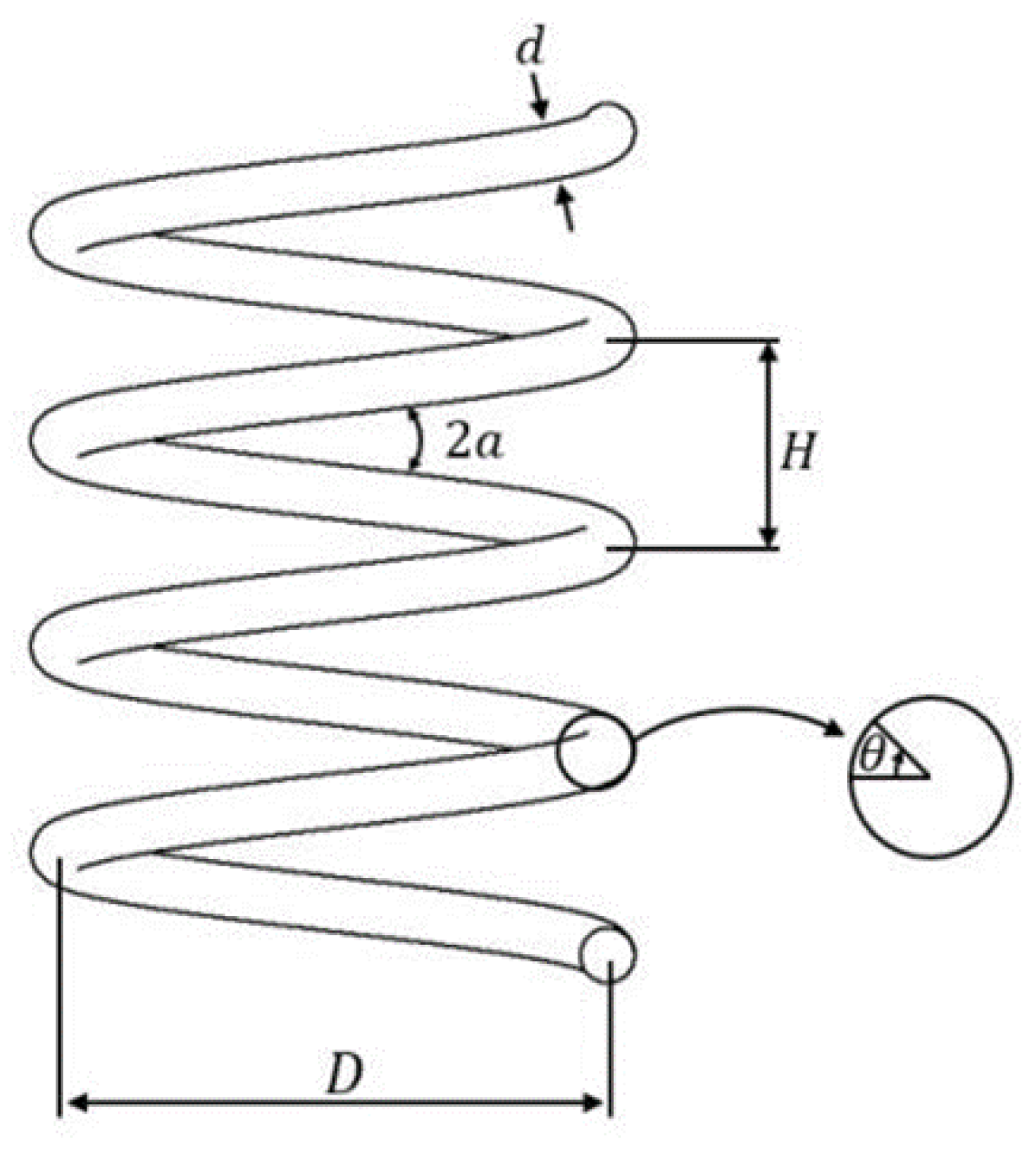
The helically coiled tube is presented schematically in
Figure 1. The inner diameter of the pipe is d (=2 r). The curvature radius of a helical tube is represented by the coil diameter D (=2 R
c). Pitch (H) is the increased distance in height per rotation of the coils. In this study, the pitch was fixed to investigate the effect of d/D in the current model. The curvature ratio (d/D) is defined as the ratio between the diameter of the pipe and the diameter of the coil. The helix angle (α) is the angle formed by the coil’s helix with the plane perpendicular to the axis.
For turbulent flow in a pipe, a viscous sublayer exists in the zone near the wall, while the central core far from the wall is turbulent. The present method adopts the law of wall and the Reynolds analogy. In the turbulence-dominated region, the velocity distribution can be represented by the logarithmic law:
where
is local friction velocity, and y is the normal distance from the wall.
The friction factor in the helically coiled tube can be calculated by integrating the velocity over the tube radius. The mean velocity of the helically coiled tube is
Using the following relation:
Using the relation, .
The following friction factor equation is obtained:
If the local wall friction velocity distribution
F(θ) is available, Equation (5) may be solved for the friction factor. The change in local wall shear stress along the perimeter of the pipe wall derived by the numerical method for turbulent flows in helically coiled pipes with varying d/D ratios at Re = 25,000 is shown in
Figure 2 [
6]. The angle is measured clockwise, beginning at the interior of the tube cross-section, and is shown in
Figure 1. The following equation is used to describe the local wall shear stress distribution as a function of the average wall shear stress and angular location for the helically coiled tubes in order to appropriately reflect the normalized wall shear stress. The applicable range of the current model is a Reynolds number for turbulent flow Re > 5000, and a d/D ratio of 0.02 to 0.083, which are available to be validated.
where
a,
b and
c are constants and depend on the ratio of pipe diameter to coil diameter (d/D).
If d/D is large, the effect of centrifugal force increases, causing the wall shear stress to be higher than in the case of a straight tube throughout most of the tube wall surface. As the spiral curvature ratio, d/D, decreases, the average value of the shear stress progressively converges to the shear stress in the straight pipe. When the helical curvature ratio, d/D, decreases, the wall shear stress does not vary significantly within and outside the coil, and the average value of the shear stress progressively converges to the straight pipe shear stress. The predicted wall friction factor for turbulent flow in the helically coiled tube may be determined by substituting Equation (7) into Equation (5).
To determine the heat transfer analytically for the helically coiled tubes, an approximate analysis that the momentum transfer in a turbulent flow is analogous to a heat transfer was used [
22]. In turbulence flow, the heat transport across a fluid element could be represented by
where
is an eddy thermal diffusivity. This equation represents the heat conduction as a sum of molecular conduction and the turbulent eddy conduction. Similarly, the shear stress in turbulent flow is
where
is an eddy diffusivity of momentum.
Dividing Equation (8) by Equation (9) gives
The momentum and heat transmission in a turbulent pipe flow depend on the same turbulent eddies. The heat flux,
q/A, is assumed to be comparable to the momentum flux,
τ, in a turbulent flow, so that the ratio,
τ/(q/A), should be constant at all radial positions. Thus,
Then, integrating Equation (10) between the wall condition and mean bulk condition gives
The heat transfer rate at the wall of the tube can be expressed by
The shear stress can be expressed as a friction factor, f, by
Substituting the expression for
and
in Equation (13) gives
This shows the relationship between the heat flux and the momentum flux in the helically coiled tube flow. The local Nusselt number was obtained as follows:
The average Nusselt number is defined as follows:
The expected average Nusselt number for turbulent flow in the helically coiled tube may be obtained by substituting Equation (17) into Equation (18). This is an analytical method for estimating the heat transfer coefficient using heat transfer and momentum transfer analogies.
3. Results and Discussion
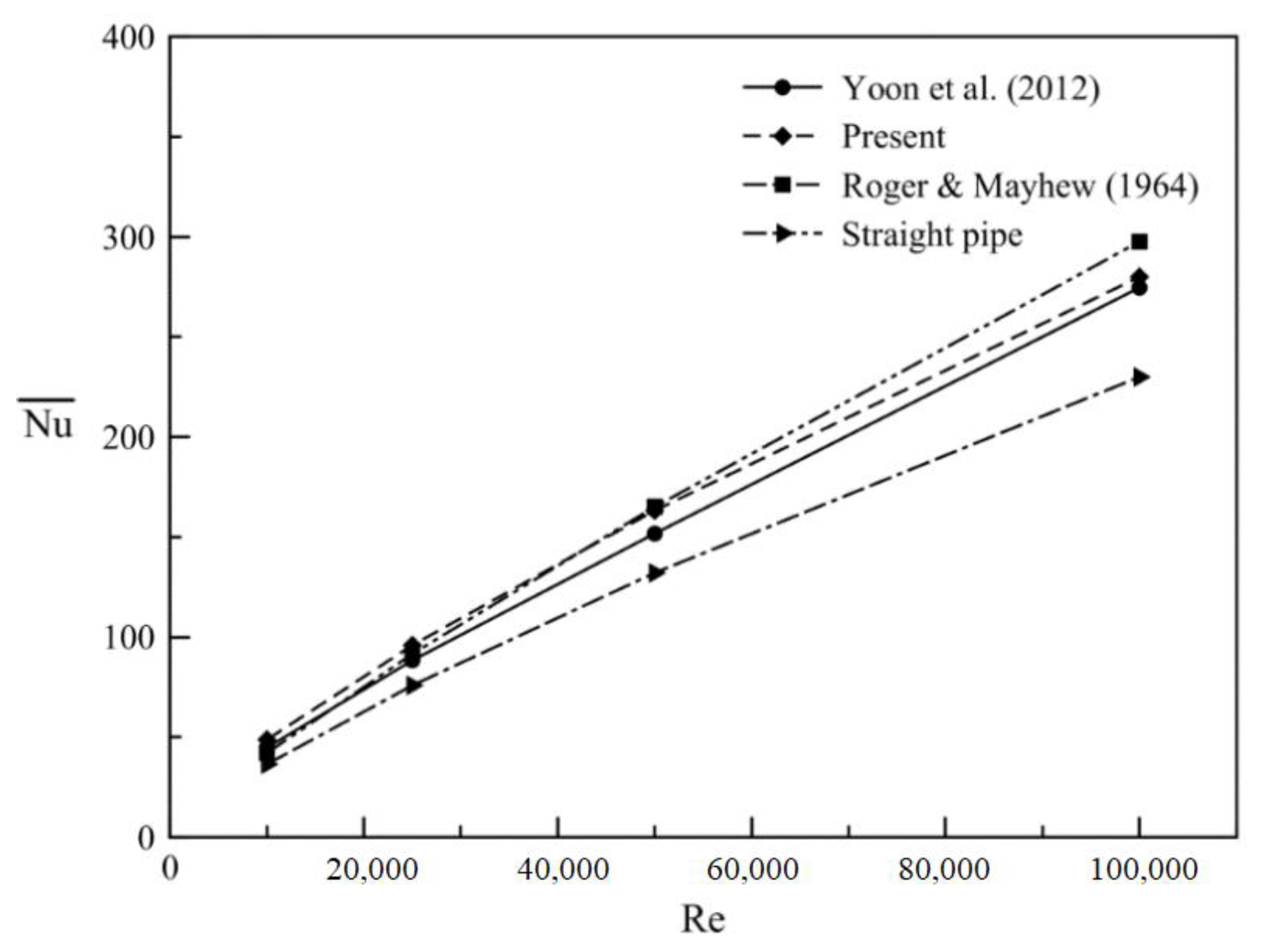
The friction factor and heat transfer rate in the turbulent flow of the helically coiled tube with constant wall heat flux were calculated using an analytical prediction method based on the theory. A comparison of the friction coefficient is presented in
Figure 3 with the previous experimental and numerical results for the helically coiled tubes with various Reynolds numbers [
9,
23,
24]. The friction factor according to the change in the Reynolds number agrees well with the results of the previous study.
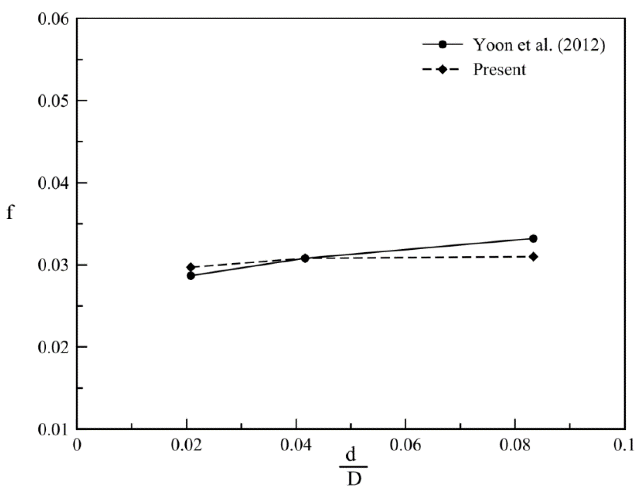
Figure 4 shows the friction factor for different spiral curvature ratios (d/D). As the curvature ratio (d/D) decreases, the influence of secondary vortices by centrifugal forces also decreases, so the friction coefficient tends to decrease. The change in the friction factor due to the change in the spiral curvature ratio (d/D) is consistent with the results of the previous study.
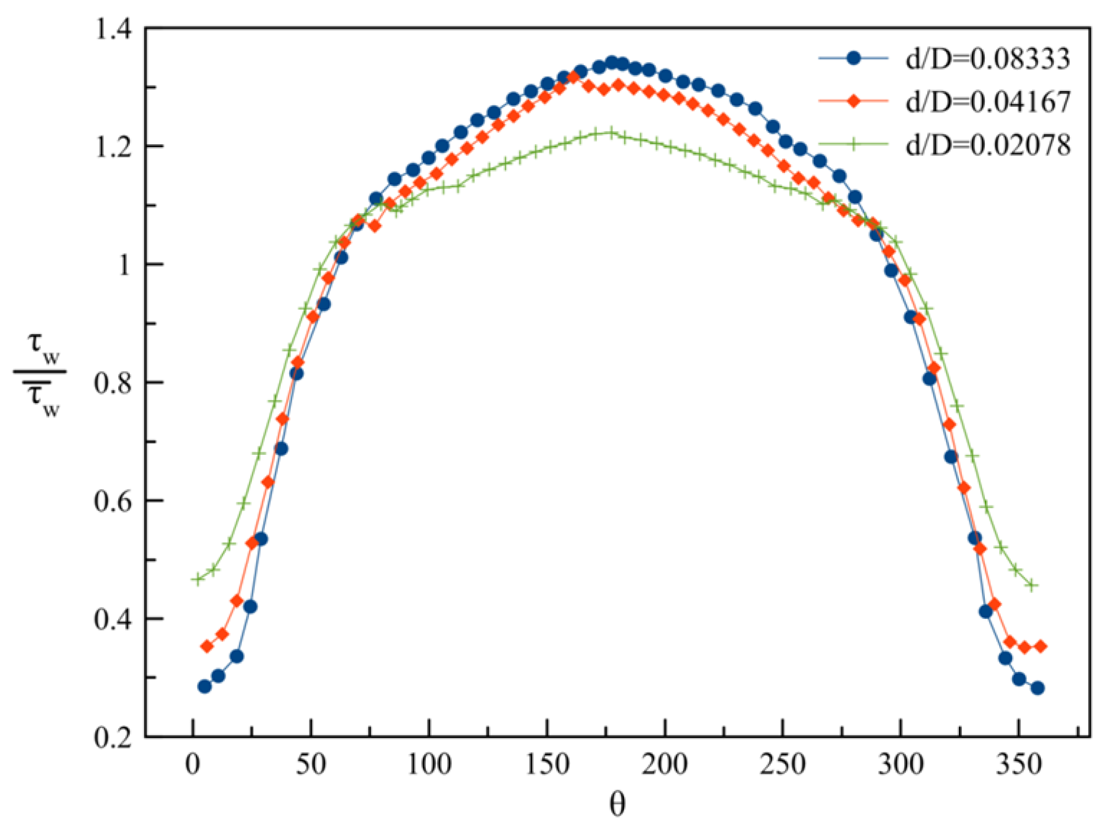
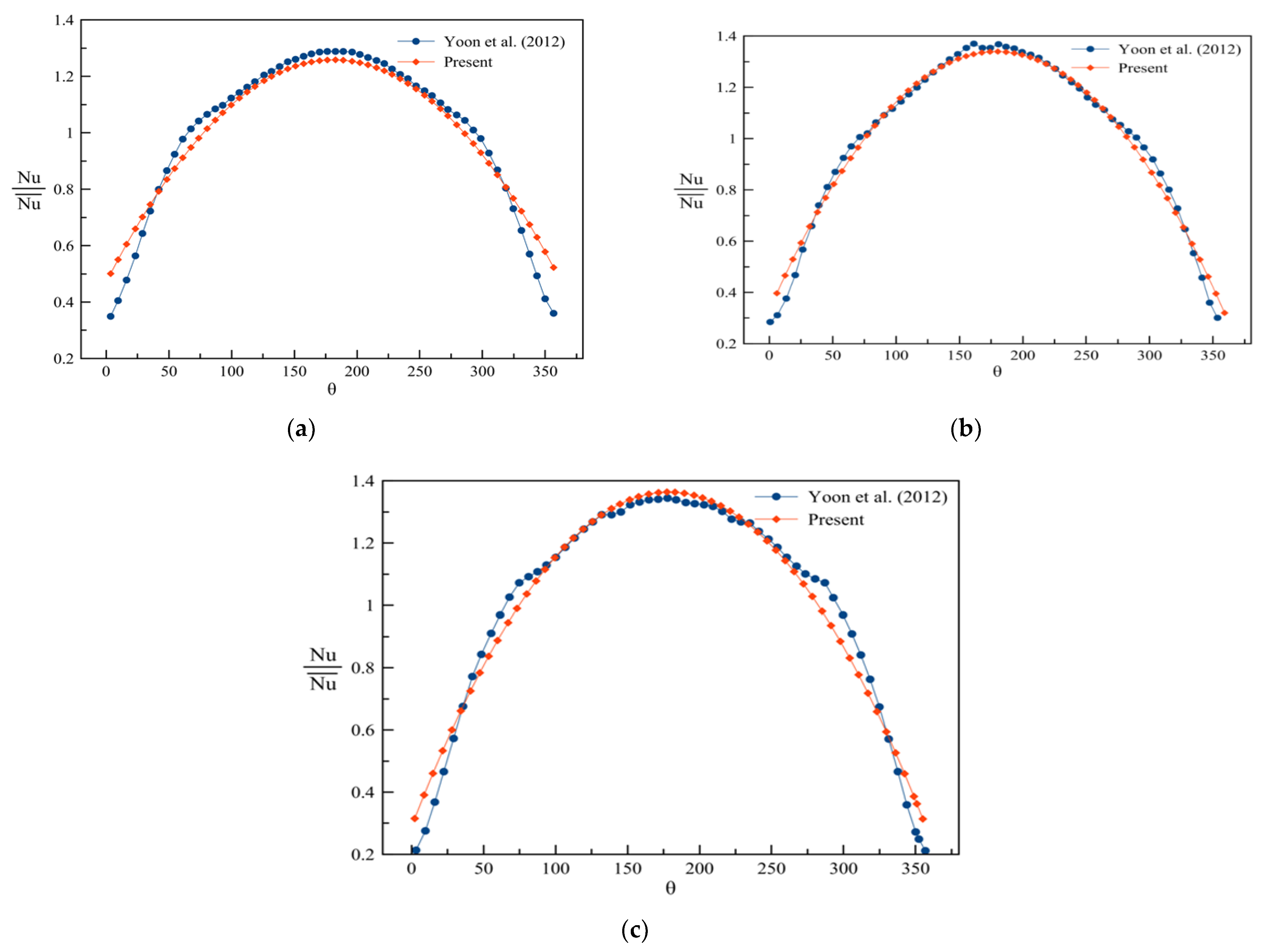
Using the Reynolds analogy for helically coiled tubes, the local Nusselt number around the circumference of the helical tube wall was determined. For the different curvature ratios (d/D) with Re = 25,000, the local Nusselt numbers were normalized with the average Nusselt number obtained using Equation (18). The local Nusselt number distribution to the average Nusselt number around the tube wall’s circumference is shown in
Figure 5. From the inner side of the coil, the angle was measured clockwise. The centrifugal force of the spiral tube increases the heat transfer by creating a secondary vortex in the tube and simultaneously increases the flow rate outside the spiral coil. The effect of reducing the heat transfer inside the tube and increasing the heat transfer outside the tube was quantitatively identified. As d/D increased, it can be seen that the heat transfer rate increased significantly in the vicinity of θ = 180°. The decrease in the heat transfer rate in the inner region of the tube was smaller than the rate of increase on the outside. As a result, the total average heat transfer rate was higher than in the case of a straight pipe. The heat transfer rate represents a value larger than the average value in a wider area in the circumferential direction.
Figure 6 compares earlier experimental and numerical data for helically coiled tubes with varying Reynolds numbers [
24,
25,
26] with the change in the average Nusselt numbers predicted by Equation (18) as the Reynolds number varies. The Nusselt number predicted by the experimental correlation agrees quite well with the current analytical method. When compared to a straight pipe, the average heat transfer rate is higher.
The effect of the centrifugal force on the heat transfer was investigated.
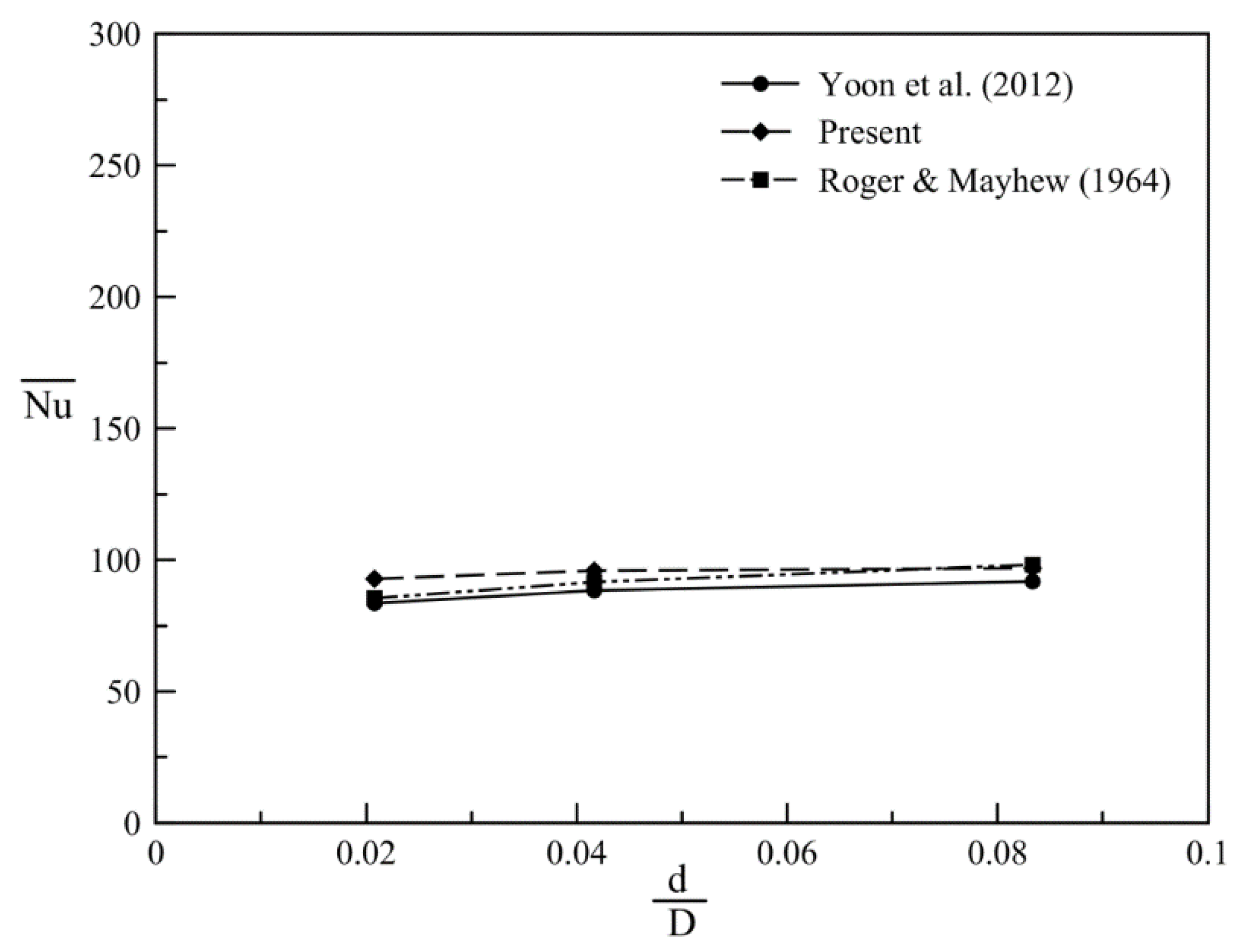
Figure 7 depicts the average Nusselt number as a function of the spiral curvature ratio (d/D). As d/D increases, so does the effect of the secondary vortices by centrifugal forces and so does the heat transfer rate. The variation in the average Nusselt number caused by the spiral curvature ratio (d/D) is consistent with the previous experimental correlation and numerical results.


