Abstract
The trace water content in industrial oil critically affects the operational stability and service life of industrial equipment and serves as a key indicator for evaluating oil quality. Therefore, the rapid, sensitive, and visual detection of trace water in oil is of great engineering significance for equipment condition monitoring and early fault warning. Existing detection methods predominantly rely on precision instruments; although they enable quantitative analysis, their operational procedures are complicated and time-consuming, which are unsuitable for on-site real-time monitoring. Consequently, there is an urgent need for a novel trace water detection sensor that offers high sensitivity, visualization, and adaptability to oil-phase environments. Herein, a coplanar electrode alternating current electroluminescent (ACEL) sensor is developed for the visual detection of trace water in oil. The ACEL sensor features a multilayer structure comprising a substrate layer, a coplanar electrode layer, and a humidity-sensitive luminescent layer. The humidity-sensitive luminescent layer consists of humidity-sensitive hydrogel and ZnS: Cu electroluminescent powder, forming a loose and porous film that enables high-sensitivity humidity sensing and simultaneously electroluminescent visual signal output. The sensing mechanism study reveals that variations in trace water content modulate the dielectric properties of the humidity-sensitive layer, which further affect the electroluminescent intensity of the ACEL sensor. In addition, the ACEL sensor enables the rapid, naked-eye recognition of humidity changes under trace water conditions without the need for precision instruments, achieving a rapid response time of 3 s and a detection limit as low as 60 ppm, all making it applicable for different types of industrial oils. Thus, this ACEL sensor features a novel detection mechanism, excellent universality, fast response, and ease of operation, offering a new visual sensing strategy for trace water detection in industrial oil and holding broad prospects for practical applications.
1. Introduction
Industrial oils, including lubricating oils, insulating oils, and hydraulic oils, serve as core media for equipment lubrication, insulation, and power transmission. Their trace water content is a key indicator for evaluating oil quality [1,2,3]. The presence of trace water readily leads to problems such as oil emulsification, the corrosion of metal components, and the degradation of insulation performance, which directly affect the operational stability and service life of industrial equipment. Therefore, the development of rapid, sensitive, and visual detection methods for trace water in oil is of great engineering significance for equipment condition monitoring and early fault warning [4,5,6]. Currently, the mainstream methods for detecting trace water in oil include Karl Fischer titration [7,8], capacitance-based methods [9,10], and spectroscopy [11,12,13]. Although these methods enable quantitative detection, most rely on precision instruments and involve cumbersome operational procedures, making on-site real-time monitoring difficult [14]. Portable detection devices suffer from high detection limits and lack intuitive visual signal feedback [15]. Moreover, conventional contact-type sensors are susceptible to oil contamination, leading to performance degradation over time [16]. Consequently, there is an urgent need to develop a novel sensor that combines high sensitivity, visual readout, fast response, and adaptability to oil-phase environments.
To address these challenges, we report a coplanar electrode alternating current electroluminescent (ACEL) sensor for the visual detection of trace water in oil. The proposed sensor adopts a multilayer structure comprising a substrate, a coplanar electrode layer, and a humidity-sensitive luminescent layer. The humidity-sensitive luminescent layer is composed of humidity-sensitive hydrogel and ZnS: Cu electroluminescent phosphor. The hydrogel enables the rapid response to humidity changes [17,18,19,20,21], while the ACEL effect produces visible light signals [22,23,24,25,26,27]. Specifically, the high hydrophilicity of the hydrogel induces dielectric property changes in the humidity-sensitive luminescent layer, which in turn modulates the electroluminescence intensity, thereby enabling visual sensing of trace water in oil. The detection limit, response speed, and applicability for different oil types are systematically investigated, and its utilization for the naked-eye visual detection of trace water in oil is demonstrated. This study presents an ACEL sensor for on-site industrial oil analysis, providing a theoretical and practical basis for visual, rapid trace water detection.
2. Structure and Characterization of the ACEL Sensor
2.1. Structure and Characterization of the ACEL Sensor
A schematic diagram of the ACEL sensor is illustrated in Figure 1a, which consists of a substrate layer, a coplanar electrode layer, and a humidity-sensitive luminescent layer. The bottom substrate of the sensor is an FR4 printed circuit board (PCB), which provides robust mechanical support for the entire device. The electrode layer consists of coplanar copper films with a thickness of 35 μm. The humidity-sensitive luminescent layer is formed by hydrogel and zinc sulfide (ZnS: Cu) electroluminescent phosphor in a specific ratio to form a loose and porous film, which can simultaneously respond to water content and emit visible signals. An AC power supply is connected to both ends of the coplanar electrodes, and visible light emits from the gap of the coplanar electrodes. Upon dropping oil-phase liquid onto the surface of the device, the dielectric constant of the humidity-sensitive luminescent layer would be changed, resulting in a variation in luminescence brightness. A photograph of the as-prepared ACEL sensor is presented in Figure 1b (the detailed fabrication process is provided in the experimental section (Appendix A)). When an AC power supply with a voltage of 400 V and a frequency of 1000 Hz is applied, green visible light is generated in the gap region of the humidity-sensitive luminescent layer, as shown in Figure 1c. Figure 1d shows the scanning electron microscopy (SEM) characterization of the humidity-sensitive luminescent layer, which clearly presents the microscopic morphology of the humidity-sensitive layer. The ZnS: Cu electroluminescent particles size is approximately 20 μm. The hydrogel closely adheres to the surface of ZnS: Cu particles and binds the luminescent particles due to dehydration, forming a loose and porous humidity-sensitive luminescent layer. This structure facilitates the penetration of water molecules and greatly improves the sensitivity of the sensor. The infrared absorption spectrum of the hydrogel is displayed in Figure 1e. Characteristic absorption peaks of the amide group (-CONH-) can be clearly observed: the C=O stretching vibration peak of the Amide I band at about 1650 cm−1 and the N-H bending vibration peak of the Amide II band at about 1550 cm−1. This confirms the existence of amide groups in the hydrogel matrix, which is the chemical structural basis for the efficient humidity response performance of the hydrogel. Meanwhile, an obvious O-H stretching vibration peak is observed at about 3300 cm−1, indicating the presence of water molecules.
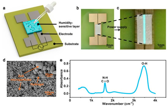
Figure 1.
Schematic diagram of the structure and device characterization of the ACEL sensor: (a) schematic diagram of the ACEL sensor; (b) photograph of the ACEL sensor; (c) luminescent image of the ACEL sensor driven by an AC power supply; (d) SEM image of the humidity-sensitive luminescent layer; (e) infrared absorption spectrum of the hydrogel.
2.2. Optimization of Electrode Parameters and Theoretical Simulation of the ACEL Sensor
To obtain an ACEL sensor with excellent visualization performance, each component of the sensor should be optimized. As we all know, the spacing of the coplanar electrode has an important impact on the electric field [28], which would in turn affect the electroluminescent intensity. Therefore, we designed sensors with different electrode spacings to achieve high-intensity electroluminescence (see the experimental section for detailed preparation methods). Figure 2a shows the photographs of the prepared ACEL sensors with different spacing distances, and the electrode spacing of the sensors was gradually set to six distances: 0.2 mm, 0.4 mm, 0.6 mm, 0.8 mm, 1.0 mm, and 1.2 mm. Figure 2b is a luminescence image of the device driven by an AC power supply. It can be observed that effective electroluminescence is achieved in all spacing regions of the sensor, and a smaller electrode spacing would introduce stronger luminescence intensity. The luminescent intensity under each electrode spacing was measured with a fiber optic spectrometer, as shown in Figure 2c. The inset in Figure 2c is the spectra peak of each electrode spacing. The spectra and peak curve indicate that as the electrode spacing gradually increases from 0.2 mm to 1.2 mm, the spectra peaks are 44,217, 13,139, 6637, 2324, 1565, and 683 counts, showing a gradual downward trend. Figure 2d is the spectra peak monitoring of each spacing, which is obtained by moving the sensor in Figure 2b at a constant speed, and the optical fiber probe of the spectrometer is fixed to continuously collect the spectra peak of each electrode spacing region from 1.2 mm to 0.2 mm. It can be seen that when the electrode spacing decreases from 1.2 mm to 0.2 mm, the spectra peak follows a stepwise increment pattern, and the luminescence intensity of the smallest spacing (0.2 mm) is about 65 times that of the largest spacing (1.2 mm).
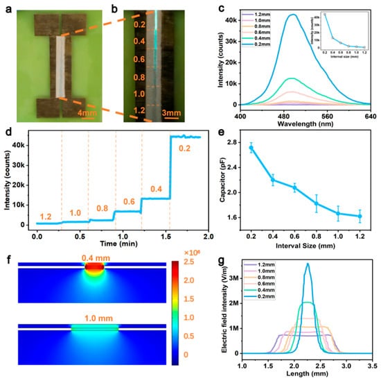
Figure 2.
Optimization of electrode parameters and theoretical analysis of the ACEL sensor: (a) photographs of an ACEL sensor with different spacing distances; (b) luminescent photograph of the sensor driven by an AC power supply; (c) luminescent intensity spectra of each spacing region (inset: spectra peak variation curve); (d) peak monitoring of luminescent intensity for each spacing; (e) capacitance of devices with different spacings; (f) electric field simulation of sensors with different electrode spacings; (g) simulated electric field distribution of sensors with different electrode spacings.
To figure out the intrinsic physical mechanism of the electrode spacing regulating the electroluminescent performance of the sensor, ACEL devices with different electrode spacings were prepared. The capacitance of each device with different electrode spacings is measured by an LCR meter as in Figure 2e. It shows that as the electrode spacing of the device increases, the capacitance value gradually decreases. Finite element simulation for electric field distribution of the ACEL sensor with different electrode spacings is performed in Figure 2f. It can be observed that when the electrode spacing is smaller (0.4 mm), the electric field among the electrode spacing region is much higher. The electric field intensity curves of different electrode spacings are also simulated in Figure 2g, and the highest electric field (3.6 MV/m) corresponding to the smallest electrode spacing (0.2 mm) is about five times the peak value (0.7 MV/m) corresponding to the largest spacing (1.2 mm), which further confirms that the electric field increases significantly with the decrease in electrode spacing. Although the 0.2 mm spacing shows the highest luminescence intensity (44,217 counts), the spacing size is too small and thus the luminescent area is tiny, which brings inconveniences to the data collection operation in the actual test process; thus, the optimal electrode spacing of the ACEL visual humidity sensor was finally determined to be 0.4 mm. Therefore, the sensor would not only possess high luminescent intensity but also is suitable for visual observation.
Except for the electrode spacing, the thickness of the humidity-sensitive luminescent layer also has a significant influence on the luminescent intensity [29,30]. Figure 3a–c illustrate the optimization of the humidity-sensitive luminescent layer thickness for the ACEL sensor, achieved by systematically investigating the influence of layer thickness on both the electroluminescent performance and capacitance of the device. First, sensor devices with humidity-sensitive luminescent layer thicknesses of 50 μm, 100 μm, 150 μm, 200 μm, and 250 μm were fabricated individually (see the experimental section for detailed preparation methods). Figure 3a shows the spectra and the spectral peaks with the thicknesses (inset) of sensors upon dropping pure oil. It indicates that the luminescent intensity of the sensor first increases and then decreases with increasing thickness, reaching a peak at approximately 200 μm. Furthermore, upon adding a mixed liquid (oil–water ratio of 400:1), the electroluminescent intensity of the sensor is shown in Figure 3b, which shows a consistent variation trend of luminescent intensity as that in Figure 3a, also reaching a peak value at 200 μm. The capacitances of the sensors when dropping two kinds of liquids are tested in Figure 3c, which indicate that the device capacitance increases continuously with the increase in layer thickness despite the amplitude of capacitance variation being quite small. Therefore, although the increase in the thickness of the humidity-sensitive luminescent layer promotes the capacitance of the dielectric layer and enhances the electric field between the electrode gaps, which is beneficial for electroluminescent intensity, on the contrary, an excessive thickness will hinder the emission of light. Therefore, 200 μm is the optimal thickness for the sensitive luminescent layer.
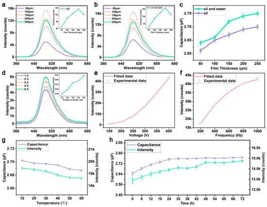
Figure 3.
Parameter optimization of the humidity-sensitive layer and effects of driving voltage and frequency for the ACEL sensor: (a) spectra of ACEL devices with varying thickness upon pure oil dropping; (b) spectra of ACEL devices with varying thickness upon oil–water mixture dropping; (c) comparison curves of the effect of humidity-sensitive layer thickness on device capacitance under different liquid dropping; (d) spectra of sensors with a varying powder-to-binder ratio of the humidity-sensitive luminescent layer; (e) relationship between luminescent intensity and voltage of coplanar electrode ACEL device; (f) relationship between luminescence intensity and frequency; (g) temperature stability test of the coplanar electrode ACEL device; (h) time-dependent variations in capacitance and luminescence intensity of the coplanar electrode ACEL device during a 72 h immersion in oil.
In addition, the mass ratio of electroluminescent powder to hydrogel in the humidity-sensitive luminescent layer significantly influences both the luminescence performance and the mechanical stability. To investigate a proper ratio, ACEL sensors were fabricated with powder-to-binder mass ratios of 1:3, 2:3, 3:3, 4:3, and 5:3 (see the experimental section for detailed preparation procedures). Figure 3d presents the electroluminescent spectra of the sensors with different powder-to-binder ratios; the inset shows the corresponding variation in spectra peak. The results indicate that the electroluminescent intensity increases progressively with an increasing powder-to-binder ratio, reaching a maximum at a ratio of 5:3. However, further increasing the powder content leads to a marked decline in the film-forming ability of the humidity-sensitive layer, potentially resulting in incomplete film formation. This, in turn, significantly compromises the mechanical integrity of the device and reduces its operational lifetime. Therefore, to achieve both high luminescence intensity and good mechanical stability, an optimized powder-to-binder ratio of 5:3 is determined.
For ACEL devices with coplanar electrodes, the driving voltage and frequency are key electrical parameters that influence the luminescent intensity [31,32]. Figure 3e illustrates the relationship between the luminescent intensity and the driving voltage. As the voltage increases from 150 V to 400 V At a fixed frequency of 1000 Hz, the luminescent intensity rises from 878 counts to 43,528 counts, presenting an approximately a 50-fold enhancement. The expression describing the relationship between the layered ACEL luminescent intensity and applied voltage is as follows [33]:
where L is the luminescent intensity, V is the applied voltage, and L0 and β are parameters determined by the device materials and structure. By fitting the experimentally measured data points, the formula for ACEL luminescent intensity is obtained as follows:
It can be seen in Figure 3e that the measured points are in good agreement with the fitted curve, and the goodness of fit is 0.998.
Similarly, at a fixed voltage of 400 V, the luminescent intensity of the ACEL sensor with varying AC frequency is shown in Figure 3f. The results indicate that the luminescent intensity of the ACEL device increases gradually to 2.45 times when the frequency rises from 200 Hz to 1000 Hz. The expression for the relationship between the luminescent intensity and the frequency of the ACEL sensor is as follows [34]:
The formula between luminescent intensity and frequency is obtained by fitting the experimentally measured data points as follows:
As shown in Figure 3f, the measured points are in good agreement with the fitted curve, with a goodness of fit of 0.986 and minimal residuals.
2.3. Stability Analysis of the Device in Simulated Industrial Oil Environments
After completing the structural design, parameter optimization, and simulation verification of the visual humidity sensor, we further conducted a systematic analysis of the device’s operational stability under simulated industrial oil conditions. Figure 3g shows the variations in the device’s capacitance and luminescence intensity over the temperature range of 10–60 °C, exploring the influence of temperature on device performance. The test results show that as the temperature increased from 10 °C to 60 °C, the device’s capacitance decreased slightly from 2.702 pF to 2.687 pF, and the luminescence intensity decreased marginally from 19,456 counts to 18,633 counts, with both indicators showing extremely low levels of variation. This result indicates that temperature changes have an extremely small impact on device performance, and the device exhibits good operational stability under common temperature fluctuations in industrial oils.
To further explore the long-term operational stability of the device in oil environments, the device was continuously immersed in oil for 72 h, and its capacitance and luminescence intensity were measured every 6 h. The corresponding test results are presented in Figure 3h. In the initial 24 h of immersion, the capacitance of the device increased slightly from 2.645 pF to 2.754 pF, and the luminescence intensity rose from 12,889 counts to 13,902 counts. During 24–48 h, the variation trend of device performance slowed down significantly, with the capacitance increasing marginally from 2.754 pF to 2.764 pF and the luminescence intensity rising slowly from 13,902 counts to 14,611 counts. After 48 h of immersion, the device performance basically stabilized, with the capacitance maintained at approximately 2.766 pF and the luminescence intensity stabilized at around 14,678 counts.
The above test results indicate that trace polar impurities, degradation products, functional additives, acids, alcohols and various contaminants in oil can exert a slight effect on the dielectric properties of the device during long-term oil immersion, yet the overall interference level is extremely low. In terms of dielectric characteristics, pure water has a dielectric constant of approximately 80, while organic acids, esters, aldehydes and ketones in oil have dielectric constants of only 3–6, alcohols of 2.5–30, and various polar additives of 2.5–6. The dielectric constant of water is far higher than that of all impurity components in oil. According to the structural and response characteristics of hydrogel, water molecules feature strong polarity and small molecular size and can construct rapid transmission channels in the hydrogel polymer network through intense hydrogen bonding interactions to realize efficient response. In contrast, polar impurity molecules in oil have larger molecular sizes and complex spatial structures, requiring overcoming the network steric hindrance of hydrogel during diffusion and penetration, and their hydrogen bonding capacity is much weaker than that of water molecules. Meanwhile, nonpolar oil molecules are repelled by hydrophobic effects and have extremely poor affinity with the hydrogel skeleton, making it difficult to invade the hydrophilic network structure. Most metal impurities in oil exist in the form of worn metal particles or macromolecular complexes, whose overall size is far larger than the pore size of the hydrogel network, so they cannot penetrate into the sensitive layer of the device. Furthermore, the single test duration of the device is only 1–2 min, and the short-term detection mode can further avoid the penetration and pollution interference of various impurities. Combined with the overall test trends, the hydrogel structure of the device’s humidity-sensitive luminescent layer shows no deactivation, degradation or damage after long-term oil immersion. It is fully demonstrated that the coplanar electrode ACEL device possesses excellent long-term operational stability in simulated oil environments.
3. Experimental Results and Discussion
3.1. Detection of Trace Water in Oil by the ACEL Sensor
To realize the detection of the trace water content in oil by the ACEL sensor, Figure 4 systematically investigates the luminescent performance and capacitance variation of the sensor under different trace water contents in mineral lubricating oil and reveals the internal working mechanism of the sensor for detecting trace water in oil through finite element simulation. Figure 4a shows the comparison of luminescent spectra of the ACEL sensor under the conditions of no liquid dropping, pure oil dropping, and mixed liquid dropping (oil–water ratio of 2000:1). The spectra show that the luminescent peak with pure oil dropping is lower than that without any liquid, while the luminescent intensity of the sensor is significantly enhanced with the oil–water mixture dropping, indicating that the presence of water can remarkably increase the luminescent intensity. The luminescence photographs of the ACEL sensor upon dropping different oil–water ratios are presented in Figure 4b. With the decrease in the oil–water ratio (increase in trace water content), the brightness of the luminescent region of the ACEL sensor shows a significant increasing trend. Figure 4c calibrates the water content (ppm) of different oil–water ratios using a coulometric titrator, where the measured water content is 60.3 ppm at an oil–water ratio of 2000:1, 66.9 ppm at 1600:1, 91 ppm at 1200:1, 104.7 ppm at 800:1, and 110.5 ppm at 400:1. The relationship between the luminescent intensity of the ACEL sensor and the oil–water ratio is shown in Figure 4d, and the luminescent intensity is positively correlated with water content. The capacitance of the ACEL sensor when dropping liquids with different water contents is measured in Figure 4e, which indicates that an increase in trace water content (or a decrease in the oil–water ratio) leads to a corresponding increase in the capacitance of the ACEL sensor, which is consistent with the spectral curve in Figure 4d. Therefore, the ACEL sensor could realize visual detection and a quantitative response of trace water at a level as low as 60 ppm for mineral lubricating oil.
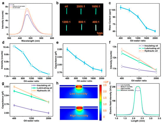
Figure 4.
Detection of trace water in oil by the visual humidity sensor: (a) electroluminescent spectra of the ACEL sensor under three conditions; (b) luminescence photographs after dropping oil–water mixtures with different trace water contents; (c) correlation between the oil–water ratio and measured trace water content; (d) spectra of the effect of the oil–water ratio on electroluminescent intensity; (e) the effect of the oil–water ratio on capacitance; (f) electroluminescent intensity upon dropping three kinds of oils at different oil–water ratios; (g) capacitance upon dropping three kinds of oils; (h) electric field simulations under high and low water content conditions; (i) electric field distribution curves under four conditions.
In addition to the commonly used mineral lubricating oil, we also evaluated the sensor’s performance in detecting trace water in other typical industrial oils, including insulating oil and hydraulic oil. The electroluminescent spectra measured upon dropping three types of oils is presented in Figure 4f, which show that under different oil–water ratios (400:1, 1200:1, and 2000:1), the luminescent intensity of the ACEL sensor deceases monotonically with an increasing oil–water ratio. It indicates that the ACEL sensor achieves a stable visual luminescence response to trace water across different oil types, demonstrating its broad applicability. The capacitances of the ACEL sensors upon dropping oils with varying water contents are also measured in Figure 4g. For all three oils, the device capacitance decreases with a rising oil–water ratio, a trend consistent with the luminescent intensity variation in Figure 4f. Therefore, owing to compositional differences among different oils, their intrinsic dielectric properties result in different baseline capacitances even at the same water content, which in turn leads to the differences in luminescent intensity.
To figure out the sensing working mechanism of the ACEL sensor, a finite element simulation model was established to analyze the variation in electric field upon dropping oil–water mixtures with different water contents [35]. A comparison of the simulated electric field distributions under high and low water content conditions is presented in Figure 4h. Obviously, under a high water content, the electric field intensity in the humidity-sensitive layer region is significantly higher than that under low water content, accompanied by a more concentrated and stronger electric field distribution. This observation explains the enhancing effect of water content on the electric field. Figure 4i further simulated the electric field under different water content conditions. The electric field distribution curves reveal that as the water content gradually increases, the peak electric field intensity exhibits an increasing trend, which in turn promotes the electroluminescent intensity of the ACEL sensor.
3.2. Application Demonstration of Visual Detection for Trace Water in Oil
Based on the device optimization and performance characterization of the ACEL sensor, an application demonstration for the visual detection of trace water in oil was designed. As shown in Figure 5a, a comparative ACEL sensor was fabricated, featuring two luminescent regions: a reference area and an experimental area. The experimental area was immersed in lubricating oil with an oil–water ratio of 2000:1 (corresponding to a trace water content of approximately 60 ppm) and continuously observed for 6 min. As shown in the luminescent photograph in Figure 5b, the luminescent intensity of the experimental area is significantly enhanced after immersion. Interestingly, the reference area, which is not in direct contact with the oil sample, also exhibits a slight increase in brightness. This phenomenon can be explained by the dynamic change in device capacitance shown in Figure 5c. During the 6 min immersion process, the device’s total capacitance increases continuously over time, indicating an overall rise in device capacitance and a corresponding enhancement of the electric field intensity, which in turn leads to the increased luminescent intensity observed in the reference area. Nevertheless, the brightness increase in the reference area is substantially lower than that of the test region.
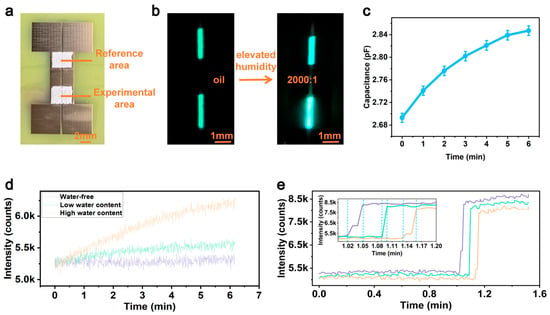
Figure 5.
Application demonstration of the ACEL sensor for trace water in oil: (a) image of the comparative ACEL sensor; (b) luminescence images before and after immersion in oil; (c) capacitance variation during immersion in oil; (d) continuous monitoring of the device spectra peak within 6 min when immersed in pure oil, low water content and high water content lubricating oil; (e) spectra peak of the ACEL sensor when dropping oil with an oil–water ratio of 400:1.
To further verify the humidity sensitivity of the ACEL sensor to trace water content, the experimental area was immersed in lubricating oil of three different conditions: pure oil, low water content (2000:1, 60 ppm), and high water content (1200:1). The spectra peak of the device was continuously monitored, as shown in Figure 5d. The results indicate that even under the low trace water content condition of 60 ppm, the device brightness increases from 5250 counts to 5500 counts, still generating a detectable light intensity response. This fully demonstrates the excellent humidity sensitivity of the ACEL sensor. Moreover, a higher water content would lead to a greater peak intensity change.
Furthermore, the humidity response speed of the ACEL sensor was evaluated, as shown in Figure 5e. An oil sample with an oil–water ratio of 400:1 was dropped onto the test region of the device. The spectra peak monitoring results reveal that within 3 s, the brightness of the experimental area rapidly increases from 5250 counts to 8250 counts, exhibiting a sharp enhancement, and the change in light intensity is distinguishable by the naked eye. Therefore, the ACEL sensor enables the naked-eye visual detection of trace water without relying on precision measuring instruments.
4. Conclusions
In summary, a coplanar electrode ACEL sensor for the visual detection of trace water in oil was proposed, featuring a loose and porous humidity-sensitive luminescent layer composed of hydrogel and ZnS: Cu electroluminescent powder. First, the sensing mechanism of the ACEL sensor was systematically elucidated. Increasing the trace water content can elevate the capacitance of the humidity-sensitive layer, which strengthens the internal electric field and further positively regulates the luminescence intensity. This design realizes dual functions of humidity perception and electroluminescent signal output. Moreover, practical application tests verified that the proposed sensor can produce distinct luminescent responses toward trace water with a detection limit as low as 60 ppm. In addition, it delivers a rapid response time of around 3 s and supports visual detection without relying on sophisticated testing equipment. Consequently, the developed ACEL sensor possesses a rational working mechanism, favorable practicability and fast response performance. It provides an innovative visual sensing route for trace water monitoring in industrial oils and holds great promise for practical industrial deployment.
Author Contributions
All authors participated in the work presented here. X.W. contributed the sensor design and writing—review and editing; Y.L. contributed the methodology and writing—original draft preparation; Z.W. contributed the resources; S.K. contributed the software; K.D. contributed the validation; X.Z. contributed the formal analysis; and funding acquisition was performed by X.W. All authors have read and agreed to the published version of the manuscript.
Funding
This research was funded by the National Natural Science Foundation of China (62405087, 52272159, 62204158), the Natural Science Foundation of Hubei Province (2024AFB173), the Scientific Research Program of the Hubei Provincial Department of Education (Q20241509), the PhD Research Start-up Fund of the Hubei University of Technology (XJ2023002501 and XJ2023009601), the Guangdong Basic and Applied Basic Research Foundation (2022B1515020072), and the Project of the Department of Education of Guangdong Province (2021ZDZX1006).
Institutional Review Board Statement
Not applicable.
Informed Consent Statement
Not applicable.
Data Availability Statement
The original contributions presented in this study are included in the article material. Further inquiries can be directed to the corresponding author(s).
Conflicts of Interest
The authors declare no conflicts of interest.
Appendix A
Appendix A.1. Experimental Methods
Materials: Hydrogels (Shanghai Mifang Electronic Technology Co., Ltd., Shanghai, China), long-lifetime electroluminescent powders (Shenzhen Yilai Technology Co., Ltd., Shenzhen, China), and lubricating oil, insulating oil and hydraulic oil (Shenzhen Dafa Lubricating Oil Technology Co., Ltd., Shenzhen, China) were used as-received in this study.
Fabrication of hydrogel-based AC electroluminescent sensors: A PCB board with dimensions of 4 cm × 3 cm × 1 mm was fixed with electrodes of 35 μm thickness and 0.4 mm spacing. Electroluminescent powder and hydrogel were uniformly mixed at a mass ratio of 5:3. The mixture was blade-coated to a thickness of 200 μm between electrodes. Finally, it was cured on a hot plate at 80 °C for 1 h to form the humidity-sensitive sensor.
Fabrication of AC electroluminescent sensors with different electrode spacings: A PCB board with dimensions of 6 cm × 3 cm × 1 mm was fixed with electrodes of 35 μm thickness and different spacings. Electroluminescent powder and hydrogel were uniformly mixed at a mass ratio of 5:3. The mixture was blade-coated to a thickness of 200 μm between electrodes. Finally, it was cured on a hot plate at 80 °C for 1 h to form the humidity-sensitive luminescent layer.
Preparation of oil–water mixtures: Oil samples were pretreated at five different oil–water ratios, with three parallel samples for each group to ensure experimental repeatability. Group 1 (2000:1): 99.95 mL of oil was measured with a pipette into a 200 mL beaker, and 0.05 mL of water was accurately added dropwise. Group 2 (1600:1): 99.94 mL of oil with 0.06 mL of water. Group 3 (1200:1): 99.92 mL of oil with 0.08 mL of water. Group 4 (800:1): 99.88 mL of oil with 0.12 mL of water. Group 5 (400:1): 99.75 mL of oil with 0.25 mL of water. After adding water, each sample was gently stirred with a glass rod for 10 min to preliminarily disperse water in the oil phase. Five labeled beakers were placed in an ultrasonic bath, which was filled with water and operated at 40 kHz for 10 min at a constant temperature of 25 °C. After ultrasonication, 2 mL of each mixture was transferred into the titration cell of a coulometric titrator. Each sample was measured three times in parallel, and the average value was taken as the final water content.
Characterizations: The transmission FTIR spectrum was obtained using a Fourier Transform Infrared Spectrometer (Nicolet iS50 FT-IR). Surface and cross-sectional micrographs of the luminescent sensing layer were measured via a Scanning Electron Microscope (ZEISS Sigma 300, Oberkochen, Germany). Water content of the oil samples was determined using a Coulometric Karl Fischer Moisture Titrator (Nittoseiko Analytech CA-310, formerly Mitsubishi Chemical Analytech, Yamato, Japan). Luminescence intensity versus wavelength curves were recorded using a Miniature Spectrometer (Hangzhou Saiman Technology Co., Ltd. S5000, Hangzhou, China). Capacitance of the sensors was measured using an LCR Digital Bridge (VICTOR 4092B).
References
- Xiao, S.; Wu, H.; Li, N.; Tan, X.; Deng, H.; Zhang, X.; Tang, J.; Li, Y. Triboelectric Mechanism of Oil-Solid Interface Adopted for Self-Powered Insulating Oil Condition Monitoring. Adv. Sci. 2023, 10, 2207230. [Google Scholar] [CrossRef] [PubMed]
- Akre, S.; Fofana, I.; Yéo, Z.; Brettschneider, S.; Kung, P.; Sékongo, B. On the Feasibility of Monitoring Power Transformer’s Winding Vibration and Temperature along with Moisture in Oil Using Optical Sensors. Sensors 2023, 23, 2310. [Google Scholar] [CrossRef] [PubMed]
- Chen, F.; He, S.; Wan, D.; Luo, Z.; Jiang, T.; Xia, X.; Wang, H.; Zhu, Y.; Zi, Y. Self-powered wireless rapid oil quality sensing system based on triboelectric-discharge effect. Nano Energy 2025, 145, 111439. [Google Scholar] [CrossRef]
- Zhao, D.; Zhu, B.; Li, L.; Liu, X.; Wen, L.; Song, Y.; Shen, H.; Li, M.; Li, X.; Wu, D. A review of methods for measuring oil moisture. Measurement 2023, 217, 113119. [Google Scholar] [CrossRef]
- Zhao, S.; Tie, L.; Guo, Z.; Li, J. Water deteriorates lubricating oils: Removal of water in lubricating oils using a robust superhydrophobic membrane. Nanoscale 2020, 12, 11703–11710. [Google Scholar] [CrossRef] [PubMed]
- Shi, H.; Zhang, H.; Gu, C.; Zeng, L. A multi-parameter on-chip impedance sensor for the detection of particle contamination in hydraulic oil. Sens. Actuators A 2019, 293, 150–159. [Google Scholar] [CrossRef]
- Lin, M. Research the instrument of Karl Fischer titration how to detect the moisture content from transformer insulating oil. J. Eng. Res. Rep. 2023, 24, 46–51. [Google Scholar] [CrossRef]
- Kosfeld, M.; Westphal, B.; Kwade, A. Correct water content measuring of lithium-ion battery components and the impact of calendering via Karl-Fischer titration. J. Energy Storage 2022, 51, 104398. [Google Scholar] [CrossRef]
- Naveed, M.F.; Amaar, A.; Khan, S.S.; Omar, M.; Larkin, S. Detection and continuous monitoring of moisture content in transformer oil using fractal-based capacitive sensor. Heliyon 2024, 10, e40995. [Google Scholar] [CrossRef]
- Zhao, H.; Han, K.; Li, Y. Strip-type flexible capacitive humidity sensor based on composite of polyimide and poly (glycidyl methacrylate): Fabrication, humidity sensitive performance and potential for detecting water content in liquids. Colloids Surf. A 2023, 675, 132092. [Google Scholar] [CrossRef]
- Zhang, W.; Webb, D.J. PMMA based optical fiber Bragg grating for measuring moisture in transformer oil. IEEE Photon. Technol. Lett. 2016, 28, 2427–2430. [Google Scholar] [CrossRef]
- Liu, J.; Fan, X.; Zhang, C.; Lai, C.S.; Zhang, Y.; Zheng, H.; Lai, L.L.; Zhang, E. Moisture diagnosis of transformer oil-immersed insulation with intelligent technique and frequency-domain spectroscopy. IEEE Trans. Ind. Inform. 2021, 17, 4624–4634. [Google Scholar] [CrossRef]
- Saleh, S.H.; Tripp, C.P. A new approach for measuring water concentration in oil using copper sulfate powder and infrared spectroscopy. Spectrochim. Acta Part A 2021, 262, 120107. [Google Scholar] [CrossRef] [PubMed]
- Jiang, J.; Wu, X.; Wang, Z.; Zhang, C.; Ma, G.; Li, X. Moisture content measurement in transformer oil using micro-nano fiber. IEEE Trans. Dielectr. Electr. Insul. 2020, 27, 1829–1836. [Google Scholar] [CrossRef]
- Hu, Y.; Dong, M.; Song, B.; Xia, C.; Xie, J.; Liu, Y.; Xing, Y. Parameters Extraction and Mechanism Analysis of the Moisture in Oil-Paper Based on the Spectral Decomposition of Dielectric Response. IEEE Trans. Dielectr. Electr. Insul. 2022, 29, 1441–1449. [Google Scholar] [CrossRef]
- Yusoff, S.; Mezher, M.; Amiri, I.; Ayyanar, N.; Vigneswaran, D.; Ahmad, H.; Zakaria, R. Detection of moisture content in transformer oil using platinum coated on D-shaped optical fiber. Opt. Fiber Technol. 2018, 45, 115–121. [Google Scholar] [CrossRef]
- Zhao, Y.; Yang, N.; Chu, X.; Sun, F.; Ali, M.U.; Zhang, Y.; Yang, B.; Cai, Y.; Liu, M.; Gasparini, N.; et al. Wide Humidity Range Applicable, Anti-Freezing and Healable Zwitterionic Hydrogels for Ion-Leakage-Free Iontronic Sensors. Adv. Mater. 2023, 35, 2211617. [Google Scholar] [CrossRef]
- Arwani, R.T.; Tan, S.C.L.; Sundarapandi, A.; Goh, W.P.; Liu, Y.; Leong, F.Y.; Yang, W.; Zheng, X.T.; Yu, Y.; Jiang, C.; et al. Stretchable ionic-electronic bilayer hydrogel electronics enable in situ detection of solid-state epidermal biomarkers. Nat. Mater. 2024, 23, 1115–1122. [Google Scholar] [CrossRef] [PubMed]
- Wang, S.; Huang, S.; Chen, Q.; Li, Y.; Duan, L.; Yu, Z.; Li, W.; Luo, H.; Li, S.; Fan, B.; et al. Emergency Wound Infection Monitoring and Treatment Based on Wearable Electrochemical Detection and Drug Release with Conductive Hydrogel. Chemosensors 2025, 13, 267. [Google Scholar] [CrossRef]
- Cha, G.D.; Lee, W.H.; Sunwoo, S.-H.; Kang, D.; Kang, T.; Cho, K.W.; Kim, M.; Park, O.K.; Jung, D.; Lee, J.; et al. Multifunctional Injectable Hydrogel for In Vivo Diagnostic and Therapeutic Applications. ACS Nano 2022, 16, 554–567. [Google Scholar] [CrossRef]
- Park, S.; Gerber, A.; Santa, C.; Aktug, G.; Hengerer, B.; Clark, H.A.; Jonas, U.; Dostalek, J.; Sergelen, K. Molecularly Responsive Aptamer-Functionalized Hydrogel for Continuous Plasmonic Biomonitoring. J. Am. Chem. Soc. 2025, 147, 11485–11500. [Google Scholar] [CrossRef]
- He, J.; Wei, R.; Ma, X.; Wu, W.; Pan, X.; Sun, J.; Tang, J.; Xu, Z.; Wang, C.; Pan, C. Contactless User-Interactive Sensing Display for Human-Human and Human-Machine Interactions. Adv. Mater. 2024, 36, 2401931. [Google Scholar] [CrossRef]
- Kim, W.; Lee, K.; Choi, S.; Park, E.; Kim, G.; Ha, J.; Kim, Y.; Jang, J.; Oh, J.H.; Kim, H.; et al. Electrochemiluminescent tactile visual synapse enabling in situ health monitoring. Nat. Mater. 2025, 24, 925–934. [Google Scholar] [CrossRef]
- Luo, X.; Wan, R.; Zhang, Z.; Song, M.; Yan, L.; Xu, J.; Yang, H.; Lu, B. 3D-Printed Hydrogel-Based Flexible Electrochromic Device for Wearable Displays. Adv. Sci. 2024, 11, 2404679. [Google Scholar] [CrossRef]
- Shanker, R.; Cho, S.; Choe, A.; Kim, M.P.; Khan, Z.; Kang, S.; Ko, H. Solution-Processable, High-Performance Flexible Electroluminescent Devices Based on High-k Nanodielectrics. Adv. Funct. Mater. 2019, 29, 1904377. [Google Scholar] [CrossRef]
- Yang, B.; Zhao, Y.; Ali, M.U.; Ji, J.; Yan, H.; Zhao, C.; Cai, Y.; Zhang, C.; Meng, H. Asymmetrically Enhanced Coplanar-Electrode Electroluminescence for Information Encryption and Ultrahighly Stretchable Displays. Adv. Mater. 2022, 34, 2201342. [Google Scholar] [CrossRef]
- Zhao, Y.C.; Xu, W.; Chen, H.Y.; Guo, W.C.; Fang, Y.; Sheng, X.J. High-Performance Dual-Responsive Sensing Skin Enabled by Bioinspired Transduction of Coplanar Square-Loop Electrodes. ACS Appl. Mater. Interfaces 2023, 15, 55163–55173. [Google Scholar] [CrossRef] [PubMed]
- López-García, J.J.; Horno, J.; Grosse, C. Combined Ionic Size and Electrode Spacing Effects on the Differential Capacitance of Confined Electrolytic Cells. J. Phys. Chem. C 2022, 126, 9154–9160. [Google Scholar] [CrossRef]
- Xie, W.; Tang, Q.; Xie, J.; Fei, Y.; Wan, H.; Zhao, T.; Ding, T.; Xiao, X.; Wen, Q. Organohydrogel-based transparent terahertz absorber via ionic conduction loss. Nat. Commun. 2024, 15, 38. [Google Scholar] [CrossRef]
- Bowen, S.D.; Herrera, L.D.; Hallinan, D.T. Diffusive and Electro-osmotic Swelling of Neutral and Ion-Containing Poly (ethylene glycol) Hydrogels. ACS Omega 2025, 10, 38413–38426. [Google Scholar] [CrossRef] [PubMed]
- Zhou, Q.; Ren, M.; Wang, K.; Dong, M. Characteristics and excitation mechanisms of high field-induced electroluminescence and discharge luminescence under square wave voltage. J. Phys. D Appl. Phys. 2026, 59, 025115. [Google Scholar] [CrossRef]
- Wang, K.; Dai, D.; Zhang, C.; Dong, M.; Ren, M. Electric Field Visualization and Quantitative Analysis Based on Electroluminescence Effect Excited by High-Frequency Square Wave Voltage. IEEE Trans. Power Electron. 2025, 40, 10581–10593. [Google Scholar] [CrossRef]
- Lin, Y.; Chen, W.; Xu, J.; Jiang, S.; Zhang, Y.; Wu, C.; Guo, T.; Zhou, X. Optimization of Flexible Alternating-current Electroluminescence Devices and its Integration with Self-powered Friction Nanogenerator. Optoelectron. Technol. 2023, 43, 226–232. [Google Scholar] [CrossRef]
- Ibañez, J.; Garcia, E.; Gil, L.; Mollar, M.; Mari, B. Frequency-dependent light emission and extinction of electroluminescent ZnS:Cu phosphor. Displays 2007, 28, 112–117. [Google Scholar] [CrossRef]
- Shi, L.; LaCour, R.A.; Qian, N.; Heindel, J.P.; Lang, X.; Zhao, R.; Head-Gordon, T.; Min, W. Water structure and electric fields at the interface of oil droplets. Nature 2025, 640, 87–93. [Google Scholar] [CrossRef] [PubMed]


Disclaimer/Publisher’s Note: The statements, opinions and data contained in all publications are solely those of the individual author(s) and contributor(s) and not of MDPI and/or the editor(s). MDPI and/or the editor(s) disclaim responsibility for any injury to people or property resulting from any ideas, methods, instructions or products referred to in the content. |
© 2026 by the authors. Licensee MDPI, Basel, Switzerland. This article is an open access article distributed under the terms and conditions of the Creative Commons Attribution (CC BY) license.