Article

An Oscillator without Linear Terms: Infinite Equilibria, Chaos, Realization, and Application

by
Othman Abdullah Almatroud
1,
Victor Kamdoum Tamba
2,
Giuseppe Grassi
3 and
Viet-Thanh Pham
4,*
1
Department of Mathematics, Faculty of Science, University of Ha’il, Ha’il 2440, Saudi Arabia
2
Department of Telecommunication and Network Engineering, Fotso Victor University Institute of Technology, University of Dschang, Bandjoun P.O. Box 134, Cameroon
3
Dipartimento Ingegneria Innovazione, Universita del Salento, 73100 Lecce, Italy
4
Nonlinear Systems and Applications, Faculty of Electrical and Electronics Engineering, Ton Duc Thang University, Ho Chi Minh City 758307, Vietnam
*
Author to whom correspondence should be addressed.
Mathematics 2021, 9(24), 3315; https://doi.org/10.3390/math9243315
Submission received: 8 November 2021 / Revised: 13 December 2021 / Accepted: 15 December 2021 / Published: 20 December 2021
(This article belongs to the Special Issue Chaotic Systems: From Mathematics to Real-World Applications)

Abstract

:
Oscillations and oscillators appear in various fields and find applications in numerous areas. We present an oscillator with infinite equilibria in this work. The oscillator includes only nonlinear elements (quadratic, absolute, and cubic ones). It is different from common oscillators, in which there are linear elements. Special features of the oscillator are suitable for secure applications. The oscillator’s dynamics have been discovered via simulations and an electronic circuit. Chaotic attractors, bifurcation diagrams, Lyapunov exponents, and the boosting feature are presented while measurements of the implemented oscillator are reported by using an oscilloscope. We introduce a random number generator using such an oscillator, which is applied in biomedical image encryption. Moreover, the security and performance analysis are considered to confirm the correctness of encryption and decryption processes.

1. Introduction

Nonlinear systems are studied widely because of their complex dynamics [1,2,3,4,5]. It is a challenge to analyze the solutions of such systems. In fact, numerical approaches have been attempted in numerous studies. In addition to limit cycles, chaos can appear in nonlinear systems [6]. Chaos become famous after Lorenz’s investigations [7]. Chaos was reported in various systems such as the spherical system [8], the plasma model [9], the jerk circuit [10], the modified logistic map [11], the complex Rikitake model [12], and the glucose-insulin system [13]. Interestingly, the application areas were promoted by the irregular dynamics of a chaotic system [14,15,16]. Recent applications include the steganography protocol [17], the substitution box [18], secure smart grids [19], the pseudo-random generator [20], communication for IoT [21], liquid mixtures [22], and Hash function realization [23].
Recent years have seen the emergence of systems with special equilibria [24]. Typically, we can refer to systems with infinite equilibria [25]. Jafari and Sprott used quadratic terms to propose line equilibium [25]. In the work [26], the authors applied absolute and quadratic terms to get a gallery of systems, in which equilibria are located on lines and curves. Li et al. utilized a memristor to design a memristive circuit with infinite equilibria [27]. By adding a memristive device into a system with one stable equilibrium, Pham et al. obtained a system having infinite equilibria [28]. Equilibrium points on a butterfly-like curve and two circles were explored by Sambas et al. [29,30]. Although the presence of infinite equilibria has received considerable critical attention [31,32], there are still issues which should be considered further [24].
The purpose of this investigation is to explore an oscillator with infinite equilibria. Interestingly, there is an absence of linear terms in such an oscillator. The dynamics and feasibility of the oscillator are explored by using simulations and an electronic circuit. In addition, the application of the oscillator is illustrated via biomedical image encryption. The novelty and contribution of our work is summarized as follows.
  • We introduce an oscillator without linear terms.
  • There are infinite equilibria in the oscillator.
  • The oscillator displays the boosting feature, which is useful for generating a signal with flexible amplitudes.
  • Physical realization of the oscillator is reported.
  • Special features of the oscillator are suitable for secure applications.

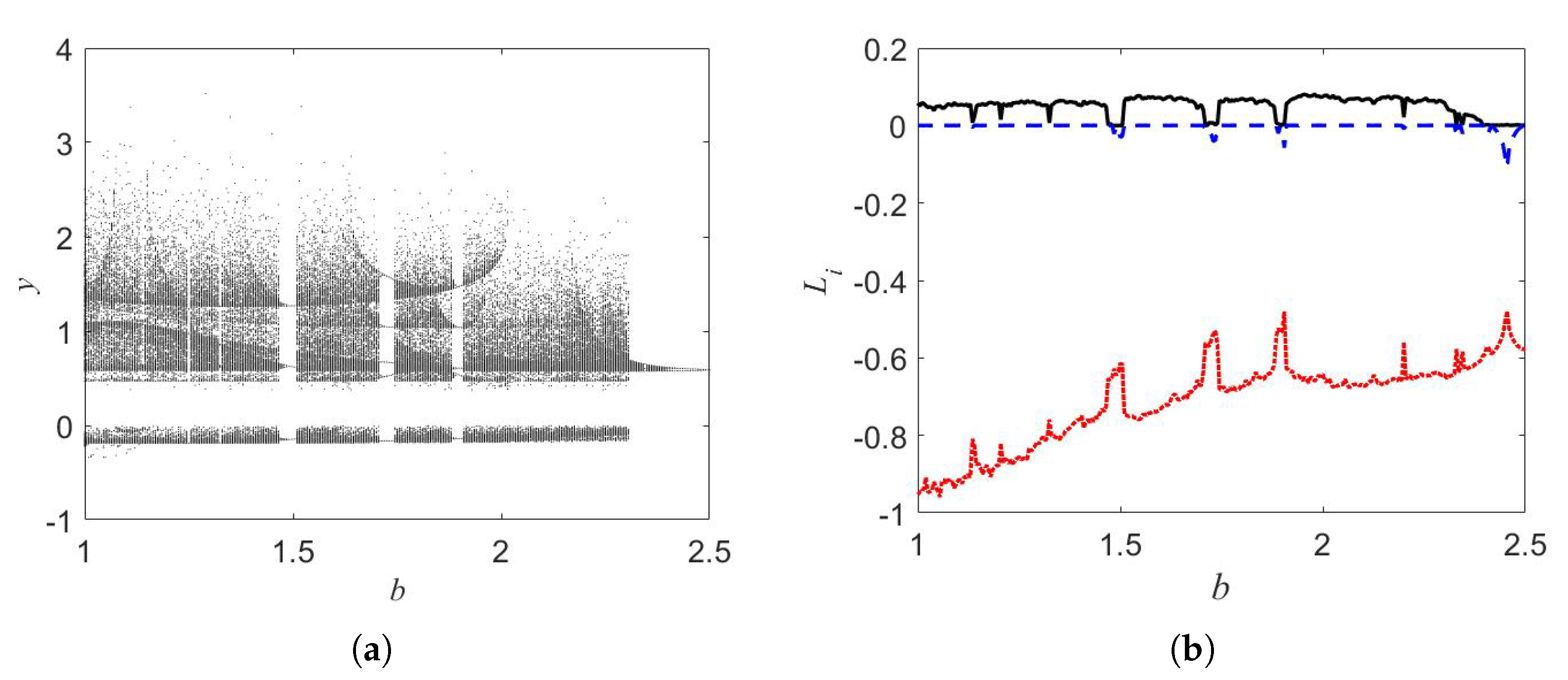
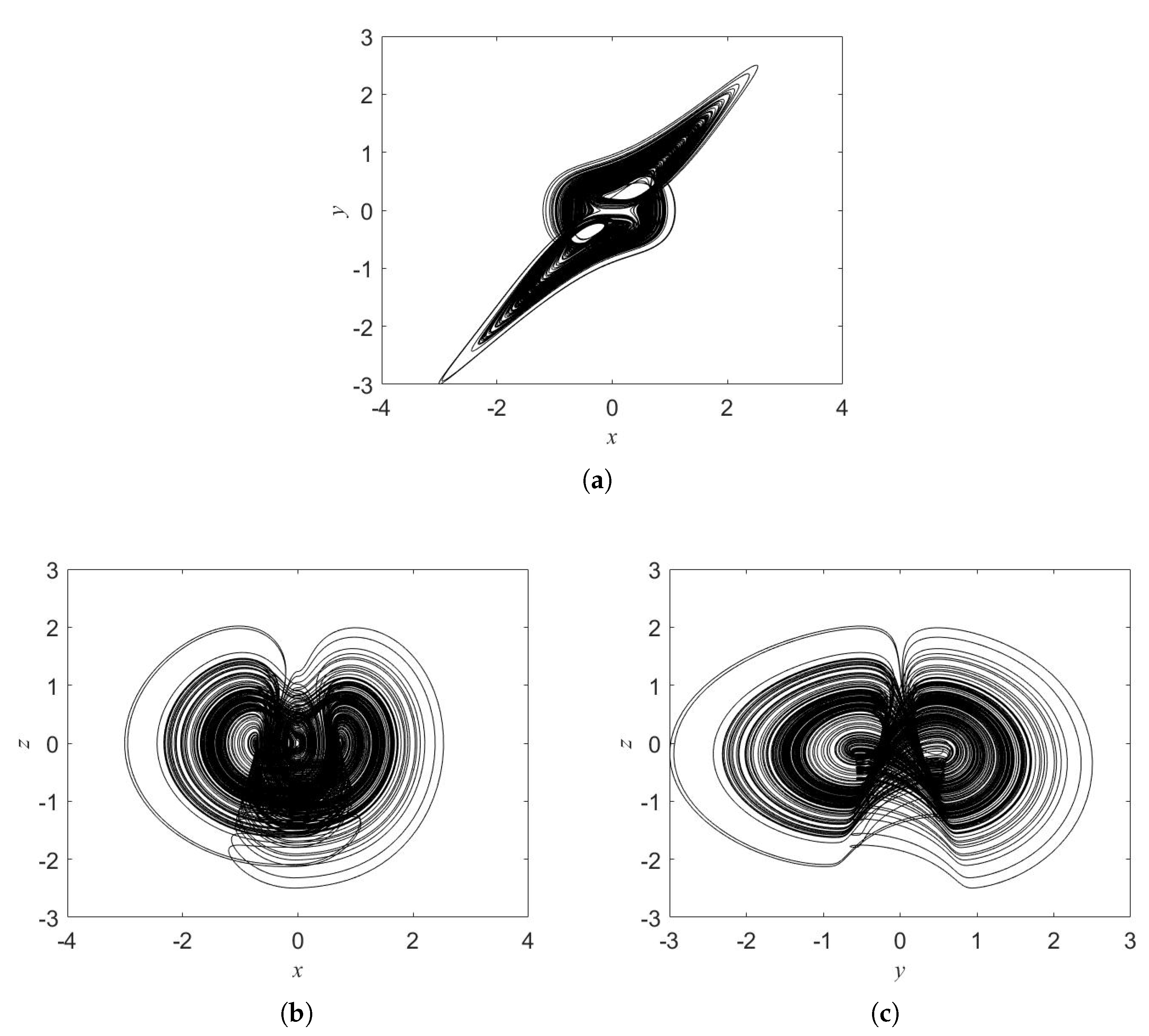
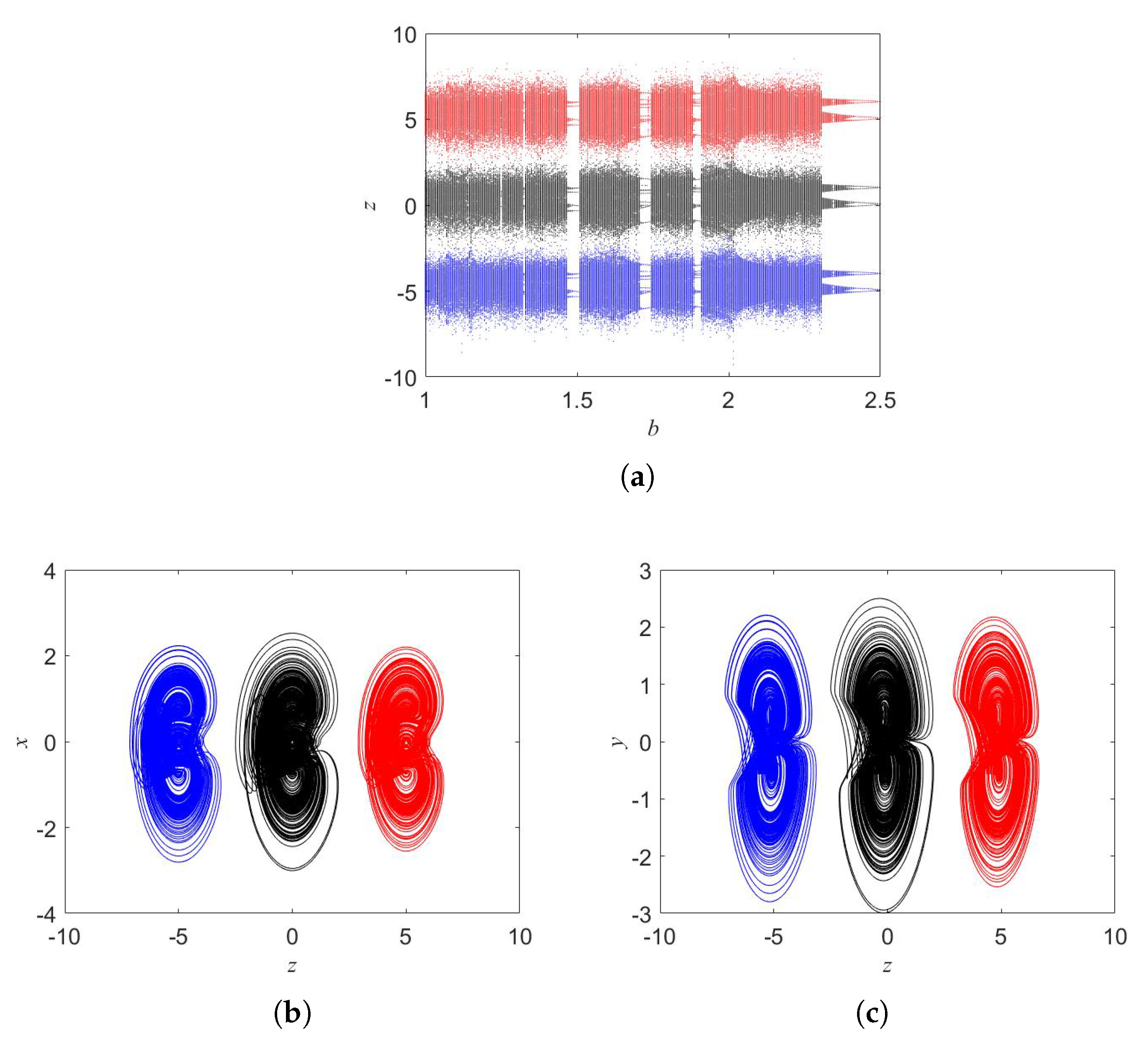
2. Oscillator and Oscillator’s Dynamics

By applying nonlinear elements (quadratic, absolute, and cubic ones), we introduce an oscillator in the following form:
x ˙ = y z y ˙ = x 3 y 3 z ˙ = a y 3 b x y + c x
In Equation (1), positive parameters are a, b, and c. We set
y z = 0
x 3 y 3 = 0
a y 3 b x y + c x = 0
for finding oscillator’s equilibrium. From Equations (3) and (4) we have
a x 3 + b x 2 c x = 0
It is simple to see that the root of Equation (5) depends on the parameters a, b, c. For a = 0.1 and c = 0.5 and b [ 1 , 2.5 ] , Equation (5) has three real roots. As a result, the oscillator has two symmetrical equilibria ( E 1 , 2 * ) and a line of equilibria ( E 3 * ) :
E 1 * α , α , 0
E 2 * α , α , 0
E 3 * 0 , 0 , z *
The bifurcation diagram is presented in Figure 1 for the parameter b. We fixed a = 0.1 , c = 0.5 and the initial conditions ( 0.1 , 0.1 , 0.1 ) . The oscillator displays chaos for some windows of b. Figure 2 illustrates chaotic attractor when b = 1 . We observe the coexisting of chaotic attractors as shown in Figure 3. Such attractors are asymmetric.
In Equation (1), the state z appears one time on the right side of equations. Therefore, a parameter k can be included into Equation (1) to control the state z as follows:
x ˙ = y ( z + k ) y ˙ = x 3 y 3 z ˙ = a y 3 b x y + c x
Boosting feature is, in fact, linear shift of coordinates of the state space. For example, boosting feature is reported for k = 0 , 5 , 5 (see Figure 4). Obviously, by changing the value of k the attractors are varied along the z axis. It is noted that the linear term k y is only appeared in Equation (9) when we include the parameter k into the Equation (1). Is this case, the oscillator can generate a signal with flexible amplitudes or a positive-amplitude signal ( z ) .
Moreover, in order to choose the parameter values according to a desired behavior and explore well the dynamics of the investigated system, we provide two-parameter bifurcation diagrams computed respectively in ( a b ) and ( a c ) planes in Figure 5. The initial conditions are fixed by ( 0.1 , 0.1 , 0.1 ) and the used parameter step is 0.005.
Figure 5 shows the various dynamical behaviors exhibited by the investigated oscillator (1) according to the value of the Largest Lyapunov Exponent (LLE). The lowest values of LLE are marked with blue, while the highest ones are indicated with dark red. The system in these ranges of parameters displays globally periodic and chaotic behaviors. Periodic oscillations are located in blue regions where LLE 0 , while chaotic ones are positioned in green, red and black regions where LLE > 0 . The white regions correspond to the unbounded solutions. Figure 5 plays an important role in the engineering system. Indeed, it helps the designer to choose the values of the system parameters according to the desired behavior. It also supports the understanding of the dynamical behavior of the system for the set of initial conditions ( 0.1 , 0.1 , 0.1 ) . However, other types of coexisting attractors are out of the scope of Figure 5.

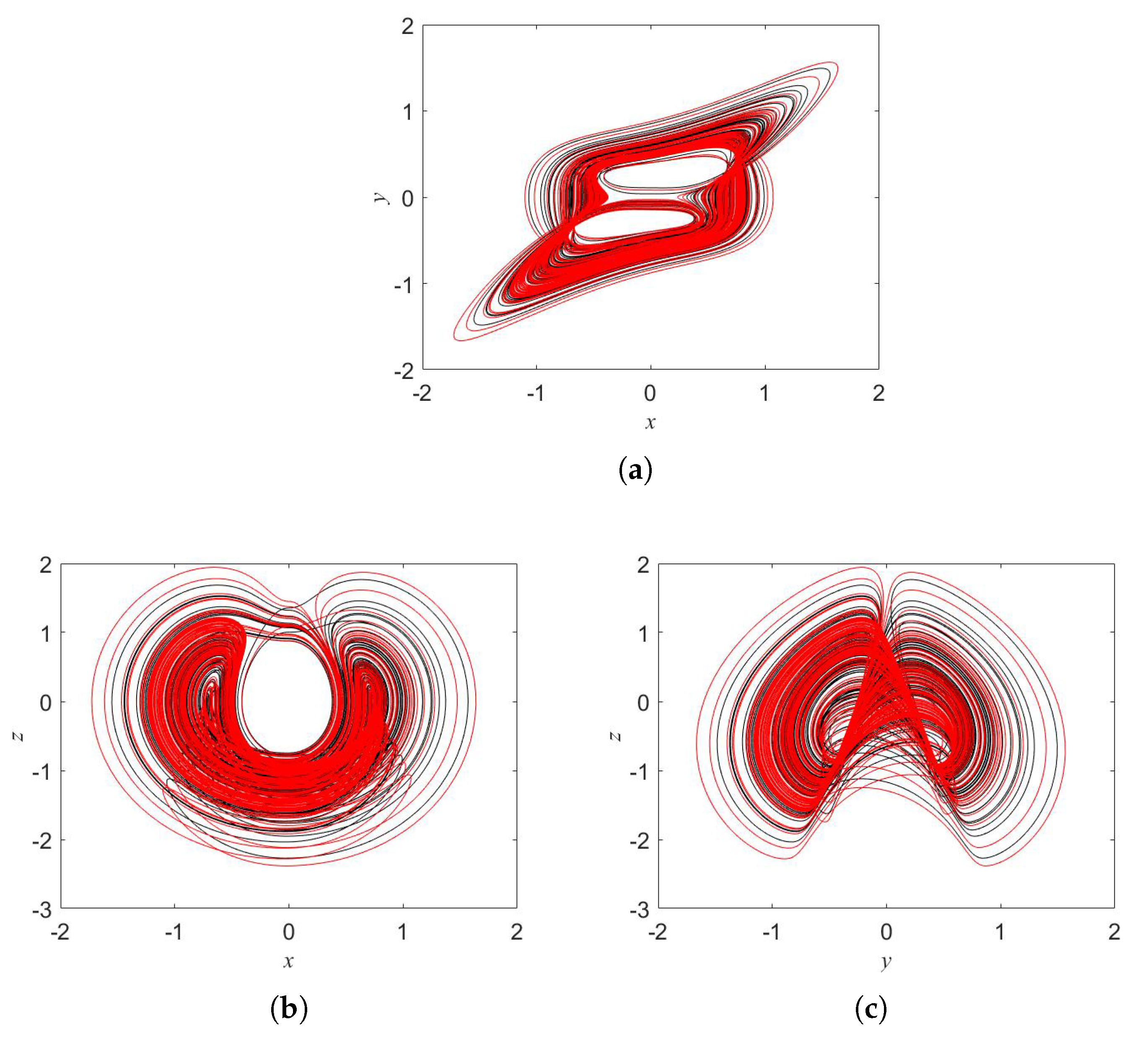
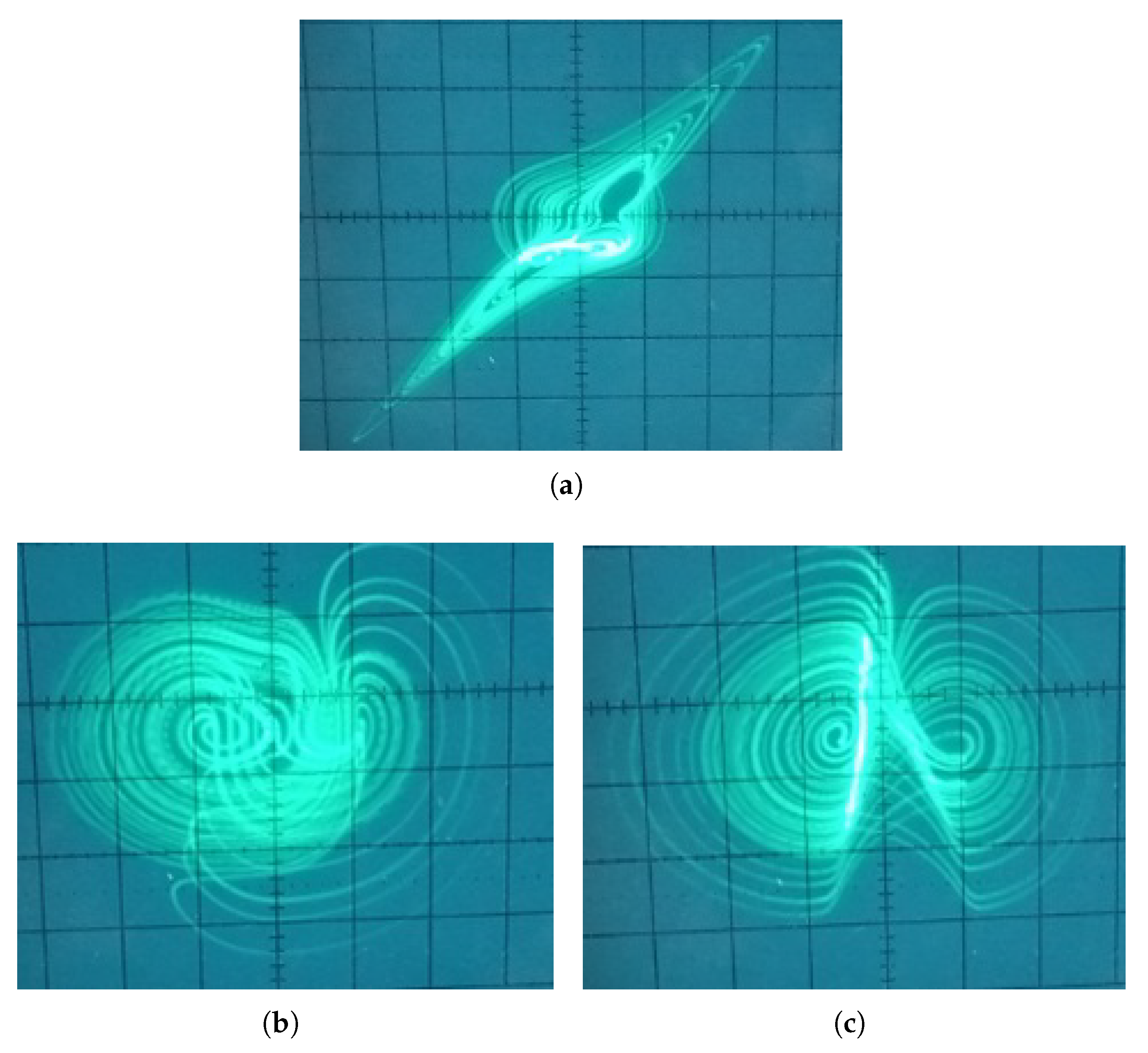
3. Oscillator Implementation

The mathematical model of a system can be transformed to its equivalent electronic circuit using basic modules (addition and integration). We design and implement an electronic circuit to reproduce the dynamics of an oscillator (1) and confirm the numerical analyses carried out in the preceding section. The proposed electronic circuit diagram for system oscillator (1) is given in Figure 6.
Considering the voltage across the capacitor V x , V y , V z , the corresponding circuit state equations can be expressed as
d V x d t = 1 10 R 1 C V y V z d V y d t = 1 100 R 2 C V x 3 1 100 R 3 C V y 3 d V z d t = 1 100 R a C V y 3 1 10 R b C V x V y + 1 R c C V x
For the selected parameters of oscillator (1) a = 0.1 , b = 1 , c = 0.5 and the initial voltages of capacitors ( V x , V y , V z ) = ( 0.1 V , 0.1 V , 0.1 V), the circuit elements are C = 10 nF, R = 10 k Ω , R 1 = 1 k Ω , R 2 = R 3 = 100 Ω , R a = 1 k Ω , R b = 1 k Ω , and R c = 20 k Ω . The chaotic attractors of the circuit are captured from the breadboard by using an analog oscilloscope (see Figure 7).
The experimental results in Figure 7 confirm that the proposed electronic circuit reproduces well the dynamics of oscillator (1). In addition, it is also possible to use the integrator-based oscillator design in the case of the boosting feature. By adding a resistor and an operational amplifier, the value of parameter k can be realized.

4. Random Number Generator (RNG) Using the Oscillator

In this section, we use the oscillator (1) to design random number generators (RNG) for biomedical image encryption applications. RNGs are aperiodic, more complex and have high entropy values. Therefore, the prediction of long-term solutions is not possible. These features are very suitable for chaos-based secure communications. The obtained numbers from an RNG process must pass the NIST-800-22 statistical tests before being used for an engineering application such as image encryption. Random number generators are commonly exploited in some relevant applications including authentication, game programming, data hiding, secure communication and encryption [33,34,35,36]. The random number generators are designed to be used for biomedical image encryption algorithms. The block diagram in Figure 8 shows the main steps in the designing process of random number generators based on oscillator (1).
The procedure of RNG starts by considering oscillator (1) as a source of chaotic generator. The system parameters ( a = 0.1 , b = 1 , and c = 0.5 ) and initial conditions ( 0.1 , 0.1 , 0.1 ) are used. After that, oscillator (1) is discretized via fourth-order Runge Kutta algorithm with time step t = 0.001 . The output results (x, y and z) are presented as float numbers. To increase the possibility to receive more successful test results in RNG, the float numbers are converted into 32 bits binary format. This conversion is done using the following MATLAB command: dec2bin(typecast(single(floatnumber),‘uint32’),32). The binary numbers from the outputs signals x, y and z are used to obtain RNG. Bits of low digits with high sensitivity are selected to construct the RNG. The following formulas are used: rngx+ = x(8LSBs), rngy+ = y(8LSBs) and rngz+ = z(8LSBs) and 1 Mbit binary sequence for NIST-800-22 statistical tests is generated.
NIST-800-22 tests are performed to verify the randomness of the random number generation’s results. The NIST-800-22 test consists to 16 different tests, including frequency, runs, rank, serial and random excursions tests. A sequence of bits is therefore valid for engineering applications when it passes all the NIST tests. Note that a test will be counted successful when the p-value is greater than 0.01. The generated random numbers from the outputs (x, y, z) passed all tests, which are recorded in Table 1. Considering the results of Table 1, the generated random numbers are effectively random and can be used for biomedical image encryption with high quality and good security. It is noted that “Nooverlapping templates”, in NIST tests “Random Excursions”, and “Random Excursions Variant” contains 148, 8, and 18 sub items, respectively. All the sub items have passed the NIST test. The value of “Nooverlapping templates" given in Table 1 has been selected randomly. The values of “Random Excursions”, and “Random Excursions Variant” in Table 1 are selected for x = 1 .

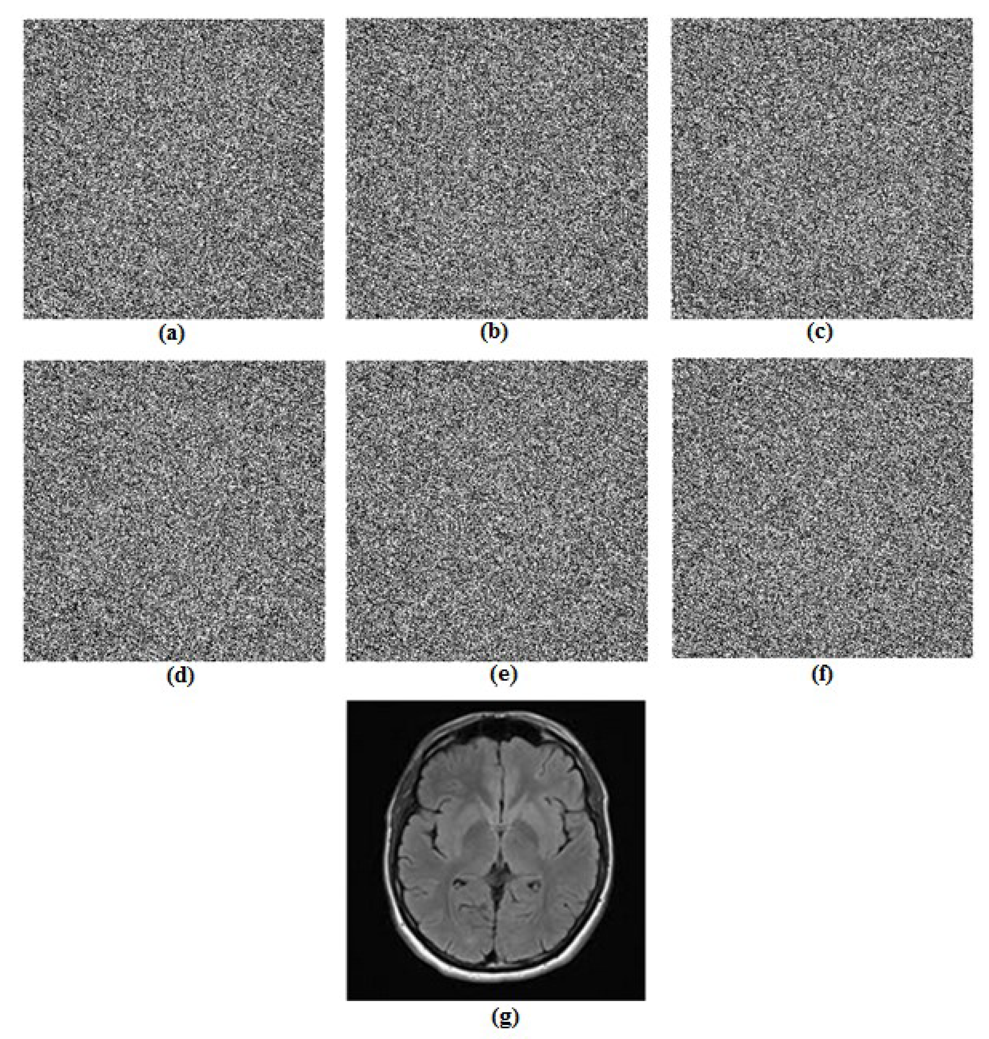
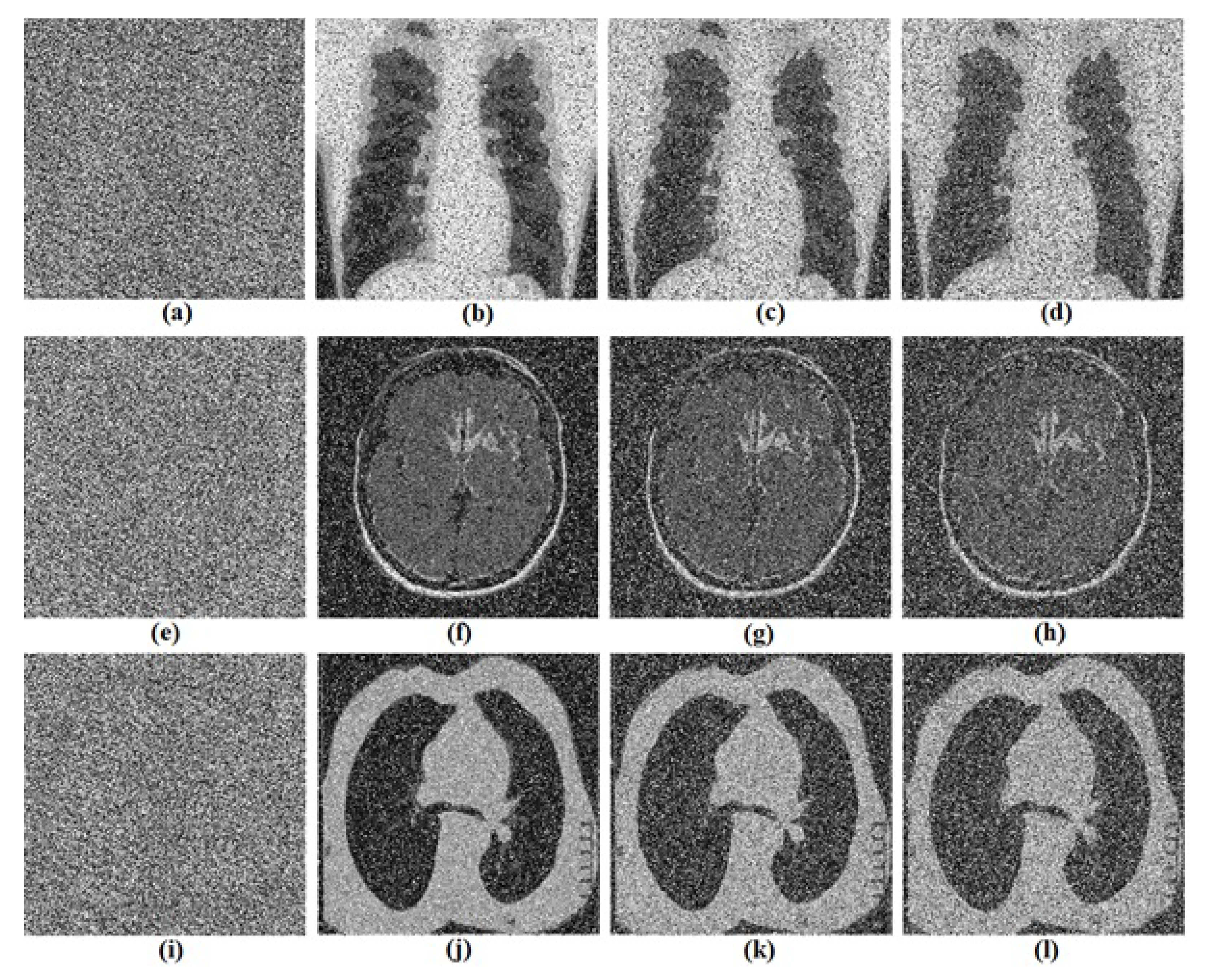
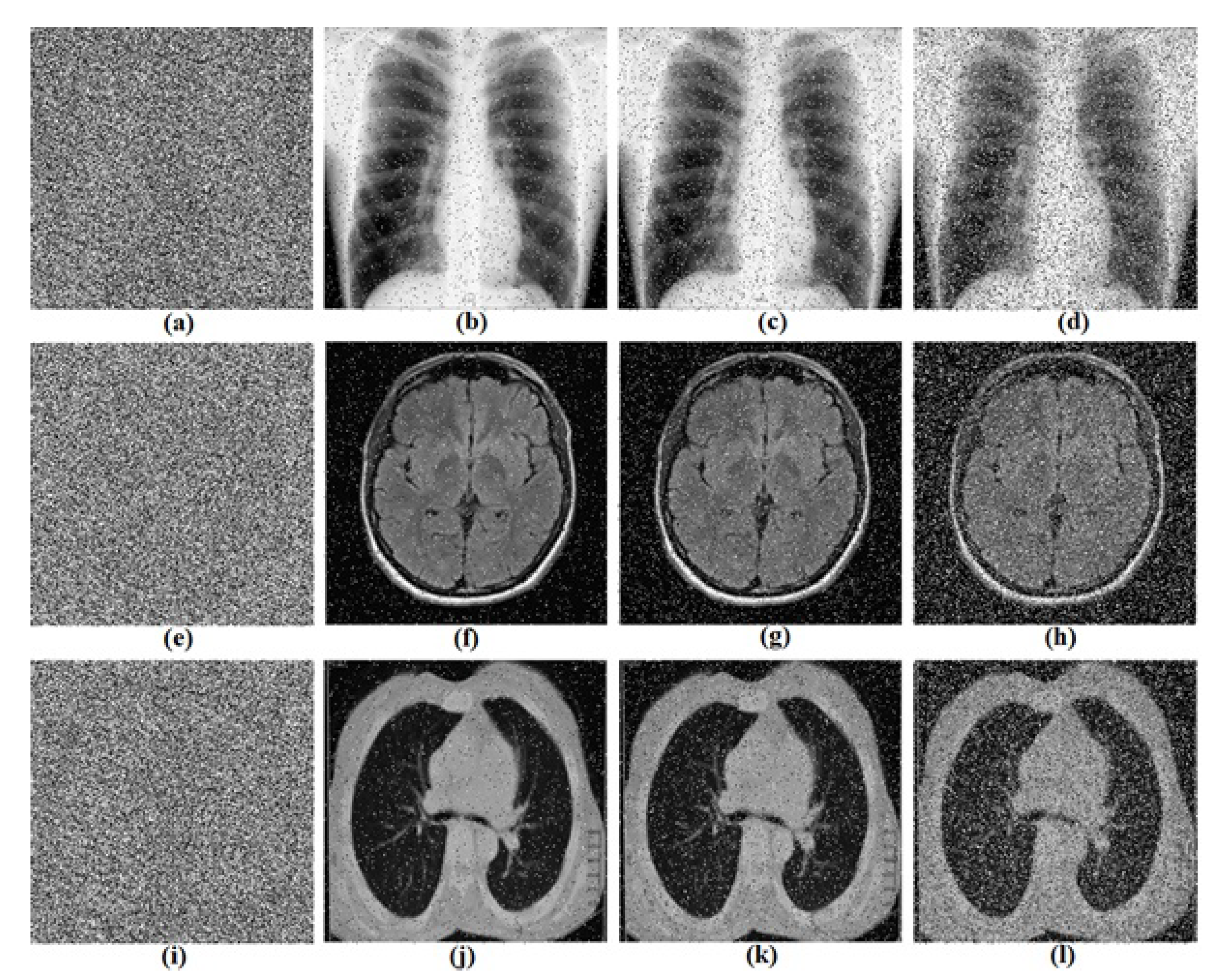
5. Biomedical Images Encryption Based on RNG Obtained from the Oscillator

Based on the developed RNG in preceding section, a biomedical images encryption algorithm is proposed. The security and performance analysis of the proposed encryption algorithm are performed.

5.1. Proposed Biomedical Images Encryption Algorithm

The main objective here is to combine the RNG obtained from oscillator (1) with the corresponding bits numbers of each pixel provided from the biomedical image. The cipher image does not need to be decrypted by anyone who is not authorized to discover a part or full information contained by the original biomedical image. The biomedical images are used here to illustrate the importance of the personal medical data protection during the transmission of these data for a medical diagnostic. The proposed biomedical image encryption process is presented in Figure 9.
In Figure 9, the parameters and initial conditions of oscillator (1) are used as keys. The RNG bits are used in the encryption and decryption processes. The original biomedical image is converted into a pixel-based binary format. The bit array of the RNG process and the biomedical image are transferred to an XOR operation to produce the cipher image. The decryption process is realized by performing the same XOR operation of the RNG bits with the cipher image. Therefore, the decrypted biomedical image is obtained.

5.2. Computational Results

The designed encryption method is analyzed by using three different biomedical images, namely “Chest”, “Brain”, and “Lung” ( 256 × 256 size). The computational results of the proposed encryption and decryption processes are provided in Figure 10 (see Figure 10a–c for original biomedical images, Figure 10d–f for cipher biomedical images and Figure 10g–i for decrypted biomedical images). We can see from Figure 10 that there is no relationship between the original images (see Figure 10a–c) and their corresponding encrypted ones (see Figure 10d–f). The decrypted images (see Figure 10g–i) seem to be the same as the original ones. This means that the encryption process does not modify the features of the original images. The encryption and decryption processes are realized successfully with high quality and good security.

5.3. Security and Performance Analysis

5.3.1. Key Space Analysis

The key space size must be greater than 2 100 [37]. The oscillator (1) consists of three parameters and three initial conditions which are used as key as mentioned above. Fixing the precision of the system to 2 17 , the key space size will be 10 17 6 = 10 102 , which is much larger than 2 100 . It is sufficient to withstand brute force attacks because of the large key space.

5.3.2. Key Sensitivity Analysis

The system under scrutiny is very sensitive to initial conditions and parameter variations. The slight change of the key makes the chaotic sequence completely different, and generates two different encrypted images. Hence, the encrypted image cannot be decrypted correctly. Figure 11 presents the test when changing the secret key 10 17 . Results show the high sensitivity of the algorithm for secret key.

5.3.3. Information Entropy

An excellent parameter indicating randomness of a signal is information entropy. Its evaluation uses the following expression
H ( m ) = i = 1 N P ( m i ) log 2 ( P ( m i ) )
where N represents the total number of all possible occurrence of signal m i and P ( m i ) represent the probability that the symbol m i appears. If the gray-scale source m = m 1 , m 2 , , m 256 emits 256 symbols with equivalent probability, then the entropy value should be equal to 8 [38] which is the ideal value of entropy for true-random information. The results of information entropy of the algorithm are displayed in Table 2. The information entropy of the cipher image is closed to 8. This serves to conclude that the cipher image is very random. Thus, the proposed algorithm has very good security performance.

5.3.4. Noise Attacks

Noise attack is studied using Gaussian as well as Salt and Pepper noises. The mean value of 0 and variance of 0.01, 0.03 and 0.05 (Gaussian noise) is added to the cipher images. The recovery images are reported in Figure 12. Likewise, by introducing the noise intensity of Salt and Pepper as 0.1, 0.3 and 0.5 in the cipher image, we obtain the recovery images in Figure 13. The results of Figure 12 and Figure 13 confirm the ability of the algorithm to avoid noise attacks.

6. Conclusions

In this work, we have introduced an oscillator in which there are infinite equilibria. It is worth noting that all terms in the oscillator are nonlinear. By investigating the oscillator, we reported different oscillator features such as chaos, multistability, and boosting attractors. moreover, the circuital attractors illustrated the oscillator’s feasibility, which is useful for applications. We have implemented a random number generator using the oscillator’s chaotic behavior. The random number generator showed good results when applying it to the encryption of biomedical images.

Author Contributions

Conceptualization, O.A.A.; Formal analysis, O.A.A.; Funding acquisition, G.G.; Investigation, V.K.T.; Methodology, V.K.T.; Resources, V.-T.P.; Software, V.-T.P.; Supervision, G.G.; Validation, V.K.T.; Visualization, O.A.A.; Writing—original draft, V.-T.P.; Writing—review & editing, G.G. All authors have read and agreed to the published version of the manuscript.

Funding

This research has been funded by Scientific Research Deanship at University of Ha’il-Saudi Arabia through project number RG-21067.

Conflicts of Interest

The authors declare no conflict of interest.

References

  1. Ikeda, K.; Daido, H.; Akimoto, O. Optical turbulence: Chaotic behavior of transmitted light from a ring cavity. Phys. Rev. Lett. 1980, 45, 709–712. [Google Scholar] [CrossRef]
  2. Ikeda, K.; Matsumoto, K. High–dimensional chaotic behaviour in system with time–delayed feedback. Physics D 1987, 29, 223–235. [Google Scholar] [CrossRef]
  3. Shilnikov, L.P.; Shilnikov, A.L.; Turaev, D.V.; Chua, L.O. Methods of Qualitative Theory in Nonlinear Dynamics; World Scientific: Singapore, 1998. [Google Scholar]
  4. Ando, B.; Graziani, S. Stochastic Resonance: Theory and Applications; Kluwer: Norwel, MA, USA, 2000. [Google Scholar]
  5. Sanjuan, M.A.F.; Grebogi, C. Recent Progress in Controlling Chaos; World Scientific: Singapore, 2010. [Google Scholar]
  6. Rössler, O.E. An equation for continuous chaos. Phys. Lett. A 1976, 57, 397–398. [Google Scholar] [CrossRef]
  7. Lorenz, E.N. Deterministic non–periodic flow. J. Atmos. Sci. 1963, 20, 130–141. [Google Scholar] [CrossRef] [Green Version]
  8. Nunez-Perez, J.C.; Adeyemi, V.A.; Sandoval-Ibarra, Y.; Perez-Pinal, F.J.; Tlelo-Cuautle, E. FPGA realization of spherical chaotic system with application in image transmission. Math. Probl. Eng. 2021, 2021, 5532106. [Google Scholar] [CrossRef]
  9. Natiq, H.; Ariffin, M.R.K.; Asbullah, M.A.; Mahad, Z.; Najah, M. Enhancing chaos complexity of a plasma model through power input with desirable random features. Entropy 2021, 23, 48. [Google Scholar] [CrossRef]
  10. Li, F.; Tai, C.; Bao, H.; Luo, J.; Bao, B. Hyperchaos, quasi-period and coexisting behaviors in second-order-memristor-based jerk circuit. Eur. Phys. J. Spec. Top. 2020, 229, 1045–1058. [Google Scholar] [CrossRef]
  11. Moysis, L.; Tutueva, A.; Volos, C.; Butusov, D.; Munoz-Pacheco, J.M.; Nistazakis, H. A two-parameter modified logistic map and its application to random bit generation. Symmetry 2020, 12, 829. [Google Scholar] [CrossRef]
  12. Pang, W.; Wu, Z.; Xiao, Y.; Jiang, C. Chaos control and synchronization of a complex Rikitake dynamo model. Entropy 2020, 22, 671. [Google Scholar] [CrossRef]
  13. Rajagopal, K.; Bayani, A.; Jafari, S.; Karthikeyan, A.; Hussain, I. Chaotic dynamics of a fractional order glucose-insulin regulatory system. Front. Inf. Technol. Electron. Eng. 2020, 21, 1108–1118. [Google Scholar] [CrossRef]
  14. Strogatz, S.H. Nonlinear Dynamics and Chaos: With Applications to Physics, Biology, Chemistry, and Engineering; Perseus Books: Boston, MA, USA, 1994. [Google Scholar]
  15. Chen, G.R. Controlling Chaos and Bifurcations in Engineering Systems; CRC Press: Boca Raton, FL, USA, 1999. [Google Scholar]
  16. Buscarino, A.; Fortuna, L.; Frasca, M.; Muscato, G. Chaos does help motion control. Int. J. Bifurc. Chaos 2007, 17, 3577–3581. [Google Scholar] [CrossRef]
  17. Abd-El-Atty, B.; Iliyasu, A.M.; Alaskar, H.; El-Latif, A.; Ahmed, A. A robust quasi-quantum walks-based steganography protocol for secure transmission of images on cloud-based e-healthcare platforms. Sensors 2020, 20, 3108. [Google Scholar] [CrossRef]
  18. El-Latif, A.A.A.; Abd-El-Atty, B.; Belazi, A.; Iliyasu, A.M. Efficient chaos-based substitution-box and its application to image encryption. Electronics 2021, 10, 1392. [Google Scholar] [CrossRef]
  19. Varan, M.; Akgul, A.; Kurugollu, F.; Sansli, A.; Smith, K. A Novel Security Methodology for Smart Grids: A Case Study of Microcomputer-Based Encryption for PMU Devices. Complexity 2021, 2021, 2798534. [Google Scholar] [CrossRef]
  20. Tutueva, A.V.; Karimov, T.I.; Moysis, L.; Nepomuceno, E.G.; Volos, C.; Butusov, D.N. Improving chaos-based pseudo-random generators in finite-precision arithmetic. Nonlinear Dyn. 2021, 105, 727–737. [Google Scholar] [CrossRef]
  21. Fataf, N.A.A.; Rahim, M.F.A.; He, S.; Banerje, S. A Communication Scheme based on Fractional Order Chaotic Laser for Internet of Things. Internet Things 2021, 15, 100425. [Google Scholar] [CrossRef]
  22. Kalayci, O.; Pehlivan, I.; Akgul, A.; Coskun, S.; Kurt, E. A New Chaotic Mixer Design Based on the Delta Robot and Its Experimental Studies. Math. Probl. Eng. 2021, 2021, 6615856. [Google Scholar] [CrossRef]
  23. la Fraga, L.G.D.; Mancillas-Lopez, C.; Tlelo-Cuautle, E. Designing an authenticated Hash function with a 2D chaotic map. Nonlinear Dyn. 2021, 104, 4569–4580. [Google Scholar] [CrossRef]
  24. Wang, Z.; Wei, Z.; Sun, K.; Shaobo He, H.W.; Xu, Q.; Chen, M. Chaotic flows with special equilibria. Eur. Phys. J. Spec. Top. 2020, 229, 905–919. [Google Scholar] [CrossRef]
  25. Jafari, S.; Sprott, J.C. Simple chaotic flows with a line equilibrium. Chaos Solitons Fractals 2013, 57, 79–84. [Google Scholar] [CrossRef]
  26. Pham, V.T.; Jafari, S.; Volos, C.; Kapitaniak, T. A gallery of chaotic systems with an infinite number of equilibrium points. Chaos Solitons Fractals 2016, 93, 58–63. [Google Scholar] [CrossRef]
  27. Li, Q.; Zeng, H.; Li, J. Hyperchaos in a 4D memristive circuit with infinitely many stable equilibria. Nonlinear Dyns. 2015, 79, 2295–2308. [Google Scholar] [CrossRef]
  28. Pham, V.T.; Jafari, S.; Kapitaniak, T. Constructing a chaotic system with an infinite number of equilibrium points. Int. J. Bifurc. Chaos 2016, 26, 1650225. [Google Scholar] [CrossRef]
  29. Sambas, A.; Vaidyanathan, S.; Bonny, T.; Zhang, S.; Hidayat, Y.; Gundara, G.; Mamat, M. Mathematical Model and FPGA Realization of a Multi-Stable Chaotic Dynamical System with a Closed Butterfly-Like Curve of Equilibrium Points. Appl. Sci. 2021, 11, 788. [Google Scholar] [CrossRef]
  30. Sambas, A.; Vaidyanathan, S.; Tlelo-Cuautle, E.; Zhang, S.; Guillen-Fernandez, O.; Hidayat, Y.; Gundarat, G. A novel chaotic system with two circles of equilibrium points: Multistability, electronic circuit and FPGA realization. Electronics 2019, 8, 1211. [Google Scholar] [CrossRef] [Green Version]
  31. Bao, B.; Zou, X.; Liu, Z.; Hu, F. Generalized memory element and chaotic memory system. Int. J. Bifurc. Chaos 2013, 23, 1350135. [Google Scholar] [CrossRef]
  32. Bao, H.; Wang, N.; Bao, B.; Chen, M.; Jin, P.; Wang, G. Initial condition-dependent dynamics and transient period in memristor-based hypogenetic jerk system with four line equilibria. Commun. Nonlinear Sci. Numer. Simul. 2018, 57, 264–275. [Google Scholar] [CrossRef]
  33. Karakaya, B.; Gulten, A.; Frasca, M. A true random bit generator based on a memristive chaotic circuit: Analysis, design and FPGA implementation. Chaos Solitons Fractals 2019, 119, 143–149. [Google Scholar] [CrossRef]
  34. Tuncer, S.A.; Kaya, T. True random number generation from bioelectrical and physical signals. Comput. Math. Methods Med. 2018, 2018, 3579275. [Google Scholar]
  35. Tuncer, T. The implementation of chaos-based PUF designs in field programmable gate array. Nonlinear Dyn. 2016, 86, 975–986. [Google Scholar] [CrossRef]
  36. Kaya, T. A true random number generator based on a Chua and RO-PUF: Design, implementation and statistical analysis. Analog Integr. Circuits Signal Process. 2020, 102, 415–426. [Google Scholar] [CrossRef]
  37. Seyedzadeh, S.M.; Mirzakuchaki, S. A fast color image encryption algorithm based on coupled two-dimensional piecewise chaotic map. Signal Process. 2012, 92, 1202–1215. [Google Scholar] [CrossRef]
  38. Tsafack, N.; Kengne, J.; Abd-El-Atty, B.; Iliyasu, A.; Hirota, K.; El-Latif, A. Design and implementation of a simple dynamical 4-D chaotic circuit with applications in image encryption. Inf. Sci. 2020, 515, 191–217. [Google Scholar] [CrossRef]
Figure 1. Changing the value of parameter b (a) Bifurcation diagram, and (b) Lyapunov exponents of the oscillator.
Mathematics 09 03315 g001
Figure 2. Chaotic attractors displayed for b = 1 (a) x-y plane, (b) x-z plane, and (c) y-z plane.
Mathematics 09 03315 g002
Figure 3. Coexisting attractors (a) x-y plane, (b) x-z plane, and (c) y-z plane for b = 2.3 with ( x ( 0 ) , y ( 0 ) , z ( 0 ) ) = ( 0.1 , 0.1 , 0.1 ) (black) and ( x ( 0 ) , y ( 0 ) , z ( 0 ) ) = ( 0 , 1 , 0 ) (red).
Mathematics 09 03315 g003
Figure 4. (a) Boosting bifurcation and boosting attractors in (b) z-x plane, and (c) z-y plane. Here colors for k = 0 , 5 , 5 are black, blue, and red, respectively.
Mathematics 09 03315 g004
Figure 5. Dynamical behaviors map. (a) 0 a 0.2 and 1 b 2.5 for c = 0.5 , (b) 0 a 0.2 and 0 c 0.8 for b = 1 . The initial conditions are ( 0.1 , 0.1 , 0.1 ) .
Mathematics 09 03315 g005
Figure 6. (a) Circuit diagram of oscillator (1), (b) absolute function circuit. The circuit includes quadruple operational amplifiers (TL084), and analog multiplier chips (AD 633JN) which are used to realize the cubic and quadrature nonlinearities, capacitors and resistors.
Mathematics 09 03315 g006
Figure 7. Chaotic attractors (a) V x - V y , (b) V x - V z , and (c) V y - V z captured from the electronic circuit of oscillator (1) implemented in breadboard for the following values of electronic components C = 10 nF, R = 10 k Ω , R 1 = 1 k Ω , R 2 = R 3 = 100 Ω , R a = 1 k Ω , R b = 1 k Ω , and R c = 20 k Ω . The initial voltage of the capacitors are ( V x , V y , V z ) = ( 0.1 V , 0.1 V , 0.1 V).
Mathematics 09 03315 g007
Figure 8. Block diagram explaining the main steps of the designing process of random number generators based on oscillator (1).
Mathematics 09 03315 g008
Figure 9. The proposed biomedical image encryption process.
Mathematics 09 03315 g009
Figure 10. Computational results of the proposed encryption process: (ac) are original biomedical images; (df) are encrypted biomedical images and (gi) are decrypted biomedical images.
Mathematics 09 03315 g010
Figure 11. Test results of key sensitivity, (a) x ( 0 ) + 10 17 , (b) y ( 0 ) + 10 17 , (c) z ( 0 ) + 10 17 , (d) a + 10 17 , (e) b + 10 17 , (f) c + 10 17 , (g) correct key.
Mathematics 09 03315 g011
Figure 12. Gaussian noise attacks test. (a,e,i) encrypted images of Chest, Brain and Lung; (b,f,j) decrypted image (variance 0.01); (c,g,k) decrypted image (variance 0.03) and (d,h,l)decrypted image (variance 0.05) respectively for Chest, Brain and Lung images.
Mathematics 09 03315 g012
Figure 13. Salt and pepper noise attacks test. (a,e,i) encrypted images of Chest, Brain and Lung; (b,f,j) decrypted image (density 0.1); (c,g,k) decrypted image (density 0.3) and (d,h,l) decrypted image (density 0.5) respectively for Chest, Brain and Lung images.
Mathematics 09 03315 g013
Table 1. Results of NIST-800-22 tests.
Test-Namep-ValueResult
XYZ
Frequency0.017360.507900.49918Passed
Block-frequency0.181890.144090.18861Passed
Runs0.965990.153810.21472Passed
Longest runs of ones0.063350.652670.74264Passed
Rank0.498850.499280.44669Passed
DFT0.792190.304420.02589Passed
No overlapping templates0.059850.077900.00453Passed
Overlapping templates0.285480.377280.79657Passed
Universal0.076180.999020.35890Passed
Linear complexity0.799800.222410.94489Passed
Serial test 10.081870.684890.22395Passed
Serial test 20.034090.708140.11562Passed
Approximate entropy0.431620.727340.61123Passed
Cumulative sums (forward)0.026100.828750.45276Passed
Cumulative sums (reverse)0.013030.558670.49918Passed
Random excursions
x = − 1
0.536670.688530.46270Passed
Random excursions variant
x = − 1
0.837840.445100.53585Passed
Table 2. Assessment of information entropy for original and encrypted images.
EntropyGreyscale Images
ChestBrainLung
Original image7.65785.83896.8364
Encrypted version7.99657.99527.9955
Publisher’s Note: MDPI stays neutral with regard to jurisdictional claims in published maps and institutional affiliations.

