Article

Nonlinear Vibrations of Bolted Rotor System Incorporating Misalignment Fault

1
School of Mechanical Engineering and Automation, Northeastern University, Shenyang 110819, China
2
Foshan Graduate School of Innovation, Northeastern University, Foshan 528312, China
3
Key Laboratory of Vibration and Control of Aero-Propulsion Systems, Ministry of Education of China, Northeastern University, Shenyang 110819, China
*
Author to whom correspondence should be addressed.
Mathematics 2026, 14(13), 2368; https://doi.org/10.3390/math14132368
Submission received: 9 June 2026 / Revised: 27 June 2026 / Accepted: 29 June 2026 / Published: 3 July 2026

Abstract

The bolted rotor system functions as a critical component in aero-engines and gas turbines. Additionally, the misalignment fault is a typical and common fault in bolted rotor systems. Nevertheless, current research on bolted rotor systems has not covered misalignment faults. Therefore, a mathematical model of bolted rotor systems incorporating misalignment faults is established in this work. The nonlinear dynamics of bolted rotor systems involving misalignment are investigated by the comparison of the frequency amplitude responses, waterfall diagrams, rotor orbits and time-varying stiffness. Moreover, an in-depth analysis is conducted on the variations in vibration behaviors of rotor systems under different misalignment degrees. Finally, the proposed model is examined using rotor-rig tests conducted under aligned and misaligned conditions. A consistent observation from the numerical and test results is that the 2× frequency resonance speed does not equate precisely to 0.5 times the critical speed. In addition, the 2× component undergoes a sudden change as the misalignment level rises.

1. Introduction

Bolted joints are extensively employed to integrate multiple shaft segments of a rotor into an entirety, thereby alleviating the processing complexity [1]. Nevertheless, under the action of loads, the interface of bolted joints can potentially give rise to nonlinear mechanical behaviors. In addition, misalignment is a common fault form in rotor systems [2,3], which may give rise to a more complicated interface response and consequently modify the nonlinear vibration response features of the bolted joint rotor system (BJRS). Currently, the influence of misalignment faults on the BJRS remains unclear. Consequently, conducting in-depth research on the vibration response of rotors assembled by bolted joints with misalignment faults not only holds significant theoretical implications but also bears substantial practical engineering application value.
In recent years, a number of researchers have carried out studies to analyze bolted joint structures. Liu et al. [4] identified via their studies that the stiffness characteristics of the interface are nonlinear and verified this behavior by experiments. Lin et al. [5] considered the anti-loosening behaviors and studied the evaluation method for bolted joints. Li et al. [6,7] presented the modeling approach for the bolt joint, and analyzed the microscopic morphology [6], wear [7], and friction contact [8]. Based on the harmonic balance method, Estakhraji et al. [9] carried out a dynamic analysis on Iwan joints. Li et al. [10] studied the nonlinear response behavior of the joints while taking fractal surfaces into account. Liu et al. [11] conducted both experimental and theoretical investigations to study the dynamic characteristic of joints under torsional vibration. They put forward an effective modeling approach for constructing thread profiles. Dreher et al. [12] carried out research on the pressure distribution at the interface of bolted joints during the process of dynamic loading. Mir-Haidari et al. [13] characterized the nonlinear forces of bolt-flange joints. The validity of this analytical method was confirmed by means of the test data obtained from within the aero-engine casing. Yang et al. [14] investigated the contact-induced nonlinear behavior of a contact-aided continuum robotic system through theoretical modeling and experimental validation. Li et al. [15] examined how the joint structure responds dynamically, then proposed a scaled-down test method. Jamia et al. [16] presented a modeling method that can characterize the nonlinear response of bolted joints. Balaji et al. [17] constructed a reduced model, with an analysis conducted on the interface contact state and nonlinear mechanical behavior. Yang et al. [18] proposed an FE reduced-order model-informed neural operator for structural dynamic response prediction. To describe the nonlinear mechanical behavior of the contact surface, the hysteresis Iwan model was established by Yuan et al. [19]. Yin et al. [20] predicted the failure behavior of bolt-flange joints by determining the model parameters and verified the model’s validity through experiments. Shu et al. [21] established a finite element model that can be used to study the performance of rotational joint structures, and studied the dynamic characteristics of bolt joints. Beaudoin et al. [22] presented a nonlinear joint model that accounts for local friction and clearance, with the model’s validity verified through experimental tests. Du et al. [23] proposed a bolt joint preload testing method, with detection accuracy improved via ultrasonic technology.
The above research carried out bolted joint structure modeling and its mechanical property analysis, providing a foundation for bolted rotor system modeling. Li et al. conducted an analysis on the bending–torsional coupling vibration [24] and stability [25] of rotors with bolted interfaces. Pirdayr et al. [26] constructed a model within the finite element framework for the bolted plate structure. Their study focused on investigating the impact of bolted joint failure on the system-level dynamic response. Li et al. [27] studied the spectral response of the rotor with bolted joints under the action of unbalanced forces. Through their research, they identified typical frequency characteristics. Du et al. [28] and Xiao et al. [29] carried out research on the coupling vibrations of disk–drum and dual-rotor systems. Zhang et al. [30] explored how rub-impact changes the vibration response of rotors containing bolted joints. A modeling scheme for electromagnetic rotors with bolted joints was presented by Zhou et al. [31]. Their findings revealed that the joint interface exerts a substantial influence on the robustness of rotor systems. Cui et al. [32] formulated the contact stiffness model of connection flanges and integrated this model into rotor systems. The bistable vibration characteristics of rotor systems and the influence of temperature were examined by Li et al. [33] and Liu et al. [34], respectively. Zhai et al. [35] integrated the progressive fatigue damage model with the extended finite element method to accurately characterize the fatigue cracking of bolt heads. In response to the issue of uncertain friction coefficients in bolted joints, Chen et al. [36] proposed a theoretical model for multi-level tangential stiffness. Yu et al. [37] proposed a nonlinear modeling approach for connection structures incorporating the slippage of the spigot. A mathematical model for the asymmetric stiffness of joint structures was established by Hong et al. [38]. Experiments on a dual-rotor system allowed them to examine how joint-interface softening impacts the vibration response. Han et al. [39] developed a model that incorporates the effect of the skewness of the principal inertia axis and subsequently analyzed its vibration behaviors. Li et al. [40,41] established the bolted rotor model and proposed a scaled model experimental method. However, how misalignment modifies the nonlinear vibration response of rotor systems with bolted joints has not been fully clarified.
In the research on misalignment faults, Tuckmantel et al. [42] established a force and moment model caused by misalignment of couplings and confirmed the validity of the model via experimental validation. Wang et al. [2] built a model for a dual-rotor configuration incorporating bearing influence and investigated the dynamics under the excitation of misalignment at the coupling. Lu et al. [43] established a dual-rotor system dynamic formulation, then discussed the dynamics of its frequency response caused by the coupled misalignment. Wang et al. [44] analyzed the nonlinear vibration characteristics and whirl behavior of dual-rotor systems with inter-shaft rub-impact. Kumar et al. [45] presented a dynamic formulation for the rotor system with active magnetic bearing support and analyzed the vibration response under misalignment fault conditions. Wang et al. [46,47] formulated the nonlinear restoring force considering misalignment and analyzed the vibration characteristics of the rotor assembly. Tang et al. [48] presented a coupled model with mixed faults of misalignment and rubbing, and analyzed the mutual influence between the faults. Miao et al. [49] examined the dynamics in rotor systems with misalignment faults. Xu et al. and Li et al. respectively presented rotor models considering parallel misalignment [50] and angular misalignment [51] of the bearing’s inner race, then analyzed the rotor system’s vibration characteristics. Guan et al. [52] and Li et al. [53] studied bearing and supporting structures in rotor systems and analyzed the related vibration characteristics. Qin et al. [54] developed an ultrasensitive self-powered smart bearing pedestal with fault locating capability. Li et al. [55] studied the nonlinear dynamic behavior of rotor systems with combined supports. Chen et al. [56] analyzed a flexible rotor system coupled with the time-varying stiffness of a faulty bearing. Moreover, Li et al. [57,58,59,60] investigated intelligent fault diagnosis and maintenance under complex operating conditions, including variable-speed diagnosis, data augmentation, and knowledge extraction and retrieval.
From the literature review presented above, previous work has substantially advanced the understanding of rotor dynamic behavior. Nonetheless, the coupled effect that bolted joints and misalignment faults exert on rotor dynamics has not been taken into account by researchers. Therefore, research on the vibration behaviors of the BJRS with misalignment is relatively limited. Moreover, the influence of misalignment faults on bolted rotor systems is still unclear. In conclusion, the primary contributions of this paper are listed below:
  • The development of a dynamic model for bolted rotor systems with misalignment faults.
  • Several vibration features that have rarely been reported are identified. The role of misalignment in the response of bolted joint rotors is clarified. Moreover, the vibration behaviors are verified by the experimental test, which demonstrates that the presented model and the analysis results are valid.
The rest of this paper is arranged as follows. Section 2 presents the proposed model. In Section 3, the impact of misalignment faults on the dynamics of the BJRS is investigated. Section 4 reports the experimental verification for the aligned and misaligned cases. The main conclusions are provided in Section 5.

2. Materials and Methods

This section formulates the dynamic equations of the BJRS under misalignment. The rotor system includes two bolted joints and is analyzed via the finite element method [61,62], as illustrated in Figure 1. Timoshenko beam theory is adopted to describe the shaft. The stiffness variation in the bolted joint and the misalignment of flexible coupling are introduced in the rotor system.

2.1. Bolted Joint Model

In this subsection, the time-varying stiffness characteristic is considered in the model of bolted joint. Furthermore, to integrate the bolted joint model into the rotor system model, an 8 degrees of freedom (DOFs) bolt joint element is proposed.
During operation, bending moments are transmitted through the bolted joint. There exists a critical angle φ0 that divides the joint stiffness into two stages. The bending stiffness kj of the joint is as follows:
k j = k j 1 ,   φ < φ 0 k j 2 ,   φ φ 0
where kj1 and kj2 denote the bending stiffness in different stages, respectively. φ0 represents the critical angle. φ is the angle formed between the two interfaces due to deformation, which is:
φ = θ x p θ x q 2 + θ y p θ y q 2
where θx and θy represent the rotations along the x and y axes. The subscripts p and q denote the node numbers at the location of the bolted joint.
An 8-DOF element is used to represent the bolted joint. The generalized displacement vectors are as follows:
q j = x p , y p , θ x p , θ y p , , x q , y q , θ x q , θ y q T
where qj denotes the generalized displacement vector of the bolted joint element. x and y represent the translations in the x-direction and y-direction, respectively.
For the bolt joint, the matrices used to simulate the motions are:
M j = m j p 0 m j p sym 0 0 J d p 0 0 0 J d p 0 0 0 0 m j q 0 0 0 0 0 m j q 0 0 0 0 0 0 J d q 0 0 0 0 0 0 0 J d q
K j = k t 0 k t sym 0 0 k j 0 0 0 k j k t 0 0 0 k t 0 k t 0 0 0 k t 0 0 k j 0 0 0 k j 0 0 0 k j 0 0 0 k j
G j = 0 0 0 0 0 0 0 0 0 0 0 0 0 0 0 0 0 0 0 J p p 0 0 0 0 0 0 J p p 0 0 0 0 0 0 0 0 0 0 0 0 0 0 0 0 0 0 0 0 0 0 0 0 0 0 0 0 J p q 0 0 0 0 0 0 J p q 0
C j = c t 0 c t sym 0 0 c j 0 0 0 c j c t 0 0 0 c t 0 c t 0 0 0 c t 0 0 c j 0 0 0 c j 0 0 0 c j 0 0 0 c j
where Mj, Kj, Gj, and Cj denote the mass, stiffness, gyroscopic, and damping matrices of the bolted joint element, respectively. mj denotes the joint mass; Jd and Jp denote the diametral and polar inertia moments, respectively; kt denotes the lateral relative stiffness of the joint; ct and cj denote the joint damping coefficients associated with translational and rotational motions, respectively.

2.2. Mathematical Model of Flexible Coupling Misalignment

The misalignment of flexible coupling will introduce extra forces to the rotor system, a phenomenon that gives rise to intense vibrations, subsequently affecting the rotor’s dynamic responses and the time-varying stiffness:
Δ e = Δ y + Δ L tan ( Δ α / 2 )
F c = m 0 Δ e Ω 2
where Δe denotes the equivalent misalignment displacement; Fc represents the misalignment force; m0 denotes the coupling mass, Δy denotes the coupling misalignment parallelism, ΔL denotes the coupling length, and Δα is the coupling misalignment angle; and Ω denotes the rotational angular speed.

2.3. Mathematical Model of the System

Timoshenko beam elements with 8 DOFs (4 per node, including 2 translational and 2 rotational) are used to model the rotor system. The disk (allocated to node 13) is integrated into the rotor system’s dynamic model, and it is treated as a rigid body to streamline the analysis (see Figure 1). Timoshenko beams are employed to simulate the shaft, and the displacement of the rotational shaft can be written as follows:
q r = x 1 y 1 θ x 1 θ y 1 ... x 22 y 22 θ x 22 θ y 22
where qr denotes the generalized displacement vector of the shaft; the subscripts 1…22 represent the total nodal number.
The beam-element mass matrix is formulated as:
M T e = ρ A l 1 + φ s 2 T 1 0 T 1 0 T 4 T 2 symm T 4 0 0 T 2 T 3 0 0 T 5 T 1 0 T 3 T 5 0 0 T 1 0 T 5 T 6 0 0 T 4 T 2 T 5 0 0 T 6 T 4 0 0 T 2
T 1 = 13 35 + 7 10 φ s + 1 3 φ s 2 ,   T 2 = 1 105 + 1 60 φ s + 1 120 φ s 2 l 2 T 3 = 9 70 + 3 10 φ s + 1 6 φ s 2 ,   T 4 = 11 210 + 11 120 φ s + 1 24 φ s 2 l T 5 = 13 420 + 3 40 φ s + 1 24 φ s 2 l ,   T 6 = 1 140 + 1 60 φ s + 1 120 φ s 2 l 2
φ s = 12 E I G A s l 2   A s = 6 A 1 + μ 7 + 6 μ I = π 64 D 4 d 4
where M T e denotes the translational mass matrix of the shaft element, and the superscript e denotes an element-level matrix. T1-T6 are the auxiliary coefficients defined in Equation (12). ρ, A and l denote the material density, cross-sectional area, and length of the shaft element, respectively. φs denotes the shear-deformation coefficient; E and G denote Young’s modulus and the shear modulus, respectively; As denotes the effective shear area; μ denotes Poisson’s ratio; I denotes the second moment of area of the shaft cross-section; and D and d denote the outer and inner diameters of the shaft element, respectively.
The inertia matrix for the beam element is obtained from:
M R e = ρ I l 1 + φ s 2 R 1 0 R 1 0 R 4 R 2 symm R 4 0 0 R 2 R 1 0 0 R 4 R 1 0 R 1 R 4 0 0 R 1 0 R 4 R 3 0 0 R 4 R 2 R 4 0 0 R 3 R 4 0 0 R 2
R 1 = 6 5 R 2 = 2 15 + 1 6 φ s + 1 3 φ s 2 l 2 R 3 = 1 30 + 1 6 φ s 1 6 φ s 2 l 2 R 4 = 1 10 1 2 φ s l
where M R e denotes the rotary-inertia mass matrix of the shaft element, and R1-R4 are the auxiliary coefficients defined in Equation (15).
The rotating-shaft stiffness matrix is written in the following form:
K B e = E I l 3 1 + φ s B 1 0 B 1 0 B 4 B 2 symm B 4 0 0 B 2 B 1 0 0 B 4 B 1 0 B 1 B 4 0 0 B 1 0 B 4 B 3 0 0 B 4 B 2 B 4 0 0 B 3 B 4 0 0 B 2
B 1 = 12 B 2 = 4 + φ s l 2 B 3 = 2 φ s l 2 B 4 = 6 l
where K B e denotes the stiffness matrix of the shaft element, and B1-B4 are the auxiliary coefficients defined in Equation (17).
The gyroscopic matrix of the rotating shaft is written as follows:
G e = ρ I 15 l 1 + φ s 2 0 G 1 0 G 2 0 0 antisymm 0 G 2 G 4 0 0 G 1 G 2 0 0 G 1 0 0 G 2 G 1 0 G 2 0 0 G 3 G 2 0 0 0 G 2 G 3 0 0 G 2 G 4 0
G 1 = 36 G 2 = 3 l 15 l φ s G 3 = l 2 + 5 l 2 φ s 5 l 2 φ s 2 G 4 = 4 l 2 + 5 l 2 φ s + 10 l 2 φ s 2
where Ge denotes the gyroscopic matrix of the shaft element, and G1-G4 are the auxiliary coefficients defined in Equation (19). The notation “antisymm” indicates that the remaining entries are obtained from matrix antisymmetry.
The motion of rotational disk can be expressed by following formula:
q d = x d y d θ x d θ y d
where qd denotes the generalized displacement vector of the disk, and the subscript d denotes the disk node index.
The disk is modeled as a rigid disk, and its unbalance is represented by an equivalent static unbalance. Based on the corresponding nodal position, the disk contributions to the rotor system, including the mass, gyroscopic, and unbalance-excitation terms, are expressed as follows:
M d = m d 0 0 0 0 m d 0 0 0 0 J d 0 0 0 0 J d
G d = 0 0 0 0 0 0 0 0 0 0 0 J p 0 0 J p 0
F d = m d e Ω 2 1 0 0 0 cos Ω t + m d e Ω 2 0 1 0 0 sin Ω t
where Md, Gd and Fd denote the mass matrix, gyroscopic matrix, and generalized unbalance-excitation vector of the disk, respectively. md denotes the disk mass; e denotes the disk eccentricity; and t denotes time. It is worth noting that, since the equivalent unbalance and the disk node are located in the same centroidal plane, the axial moment arm is zero. Therefore, no additional moments are generated about the x and y axes, and the corresponding moment components in Equation (23) are zero.
By combining the contributions from the shaft, disk, and bolted joint, together with misalignment force, the rotor governing equation can be written as:
M q · · + C Ω G q · + Kq = F d + F c
where the mass, damping, stiffness, and gyroscopic matrices of the bolted rotor system are denoted by M, C, K, and G, respectively.
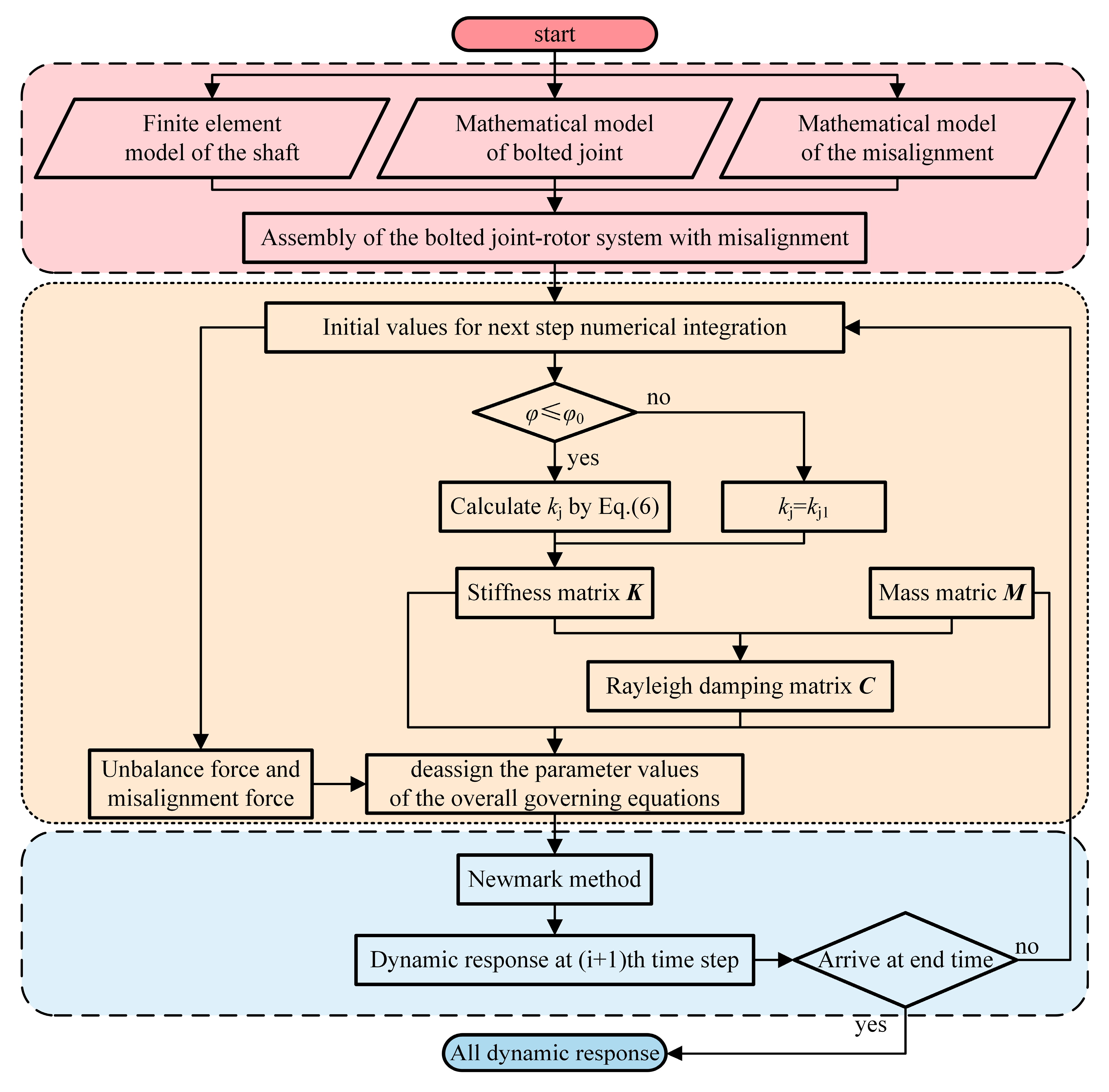
Experiments are performed to examine how coupling misalignment affects the dynamic response of the BJRS. At each prescribed rotational speed, the governing equations of the rotor system are integrated using the Newmark method, with the numerical integration process depicted in Figure 2. After the transient response is discarded, the steady-state displacement response is transformed into the frequency domain using the Fast Fourier Transform (FFT). The rotational frequency is determined from the shaft speed, and the k× component is defined as k times the rotational frequency. The critical speed and the 2× resonance speed are identified from the peaks of the 1× and 2× response amplitudes, respectively [27]. The inclusion of coupling misalignment fault as well as the stiffness variation in the bolted joint in this model is what gives this study its uniqueness. Updates to the stiffness are made by the angle φ0. The excitation is then updated according to the rotation angle. The introduction of nonlinear factors makes the entire calculation process more complex.

3. Numerical Results

This section examines the nonlinear dynamics of a misaligned BJRS, with particular emphasis on changes in bending stiffness and misalignment’s influence on rotor dynamics. Such an analysis aids in understanding the vibration mechanisms of a misaligned BJRS and enhancing system motion stability. Table 1 summarizes the main parameters used for the rotor system, while Table 2 lists the geometric parameters of the shaft elements. The two-stage bending stiffnesses of the bolted joint were selected with reference to the values reported in validated bolted joint rotor models [63]. Subsequently, the Newmark method is used to present amplitude-frequency responses, spectrum diagrams, bending stiffness, and time histories. These results serve to characterize the rotor’s dynamic properties under different conditions. It should be noted that due to the nonlinearities introduced by the bolted joints and misalignment, the frequency components discussed in this section are determined by applying the FFT to the steady-state time-domain responses obtained via the Newmark numerical integration.

3.1. Dynamic Analysis of the Bolted Joint Rotor System with Misalignment

Coupling misalignment is a prevalent fault encountered during the assembly of rotor systems [2,3]. To explore how this fault affects the dynamics of the BJRS, this section conducts a comparison between two conditions—with and without coupling misalignment.
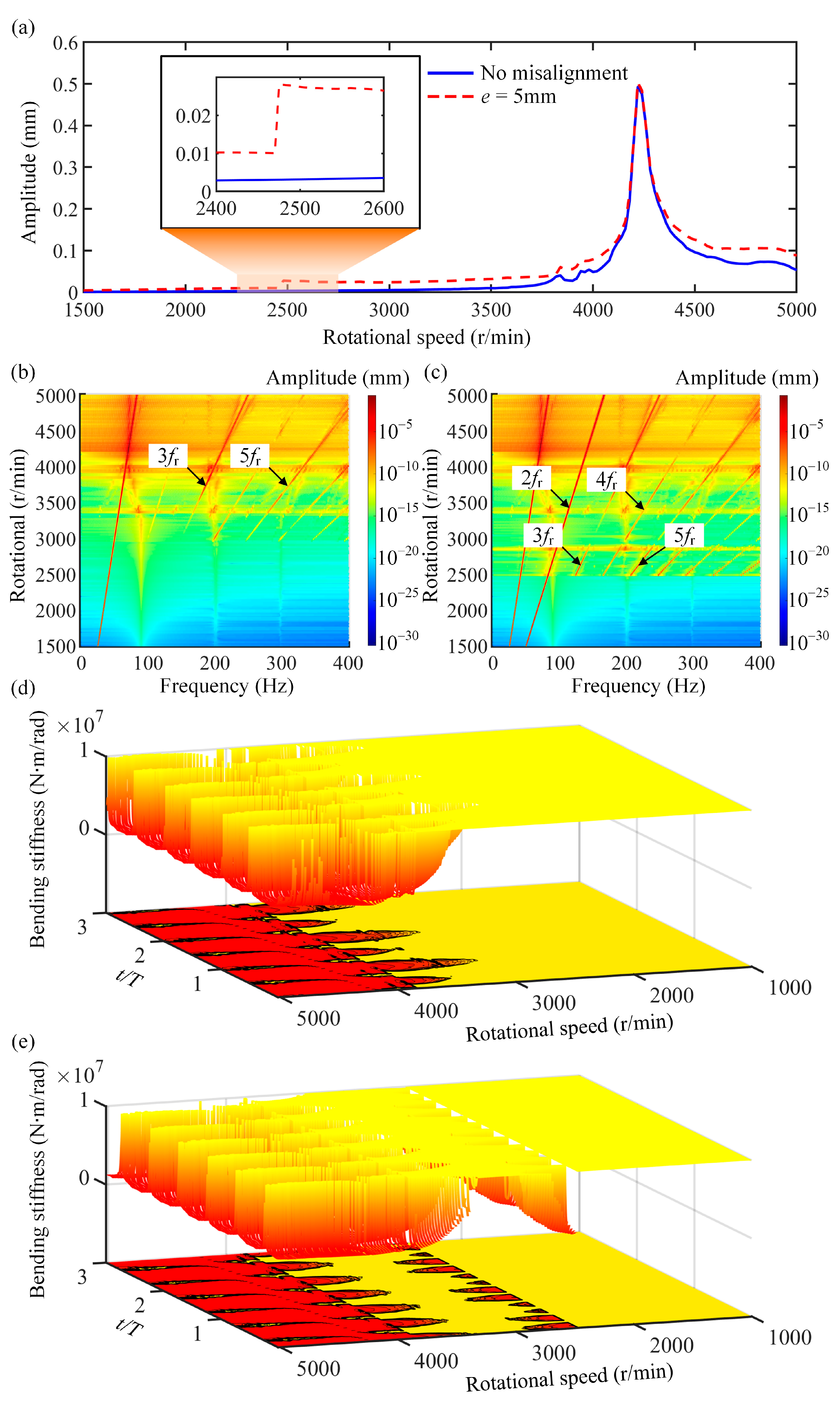
The amplitude-frequency responses, spectrum diagrams, and time-varying bending stiffness at Support 2 are shown in Figure 3. When misalignment is considered, the rotor experiences a sudden increase in vibration amplitude at approximately 0.6ωn due to the 2× resonance, as shown in Figure 3a. For a conventional linear rotor system with constant stiffness, the 2× resonance speed is generally expected to be approximately 0.5ωn. However, in the present bolted joint rotor system, the nonlinear variation in bending stiffness results in different effective stiffness states at the critical speed and the 2× resonance speed. Consequently, the actual 2× resonance speed is higher than 0.5ωn.
The spectrum diagram at different rotational speeds is illustrated in Figure 3b,c. When the misalignment fault is taken into account, the frequency components become more prominent, and a distinct 2× frequency is also observed. Moreover, complex frequency components can be observed at 2500–3000 r/min. The variation in bending stiffness at various speeds and across different time points is clearly illustrated in Figure 3d,e. The color transition from yellow to red indicates a decrease in bending stiffness. The reduction in bending stiffness becomes more pronounced when considering misalignment faults, especially at speeds of 2500–3000 r/min. This phenomenon is the reason for the emergence of multiple spectral components in the spectrum (Figure 3c).
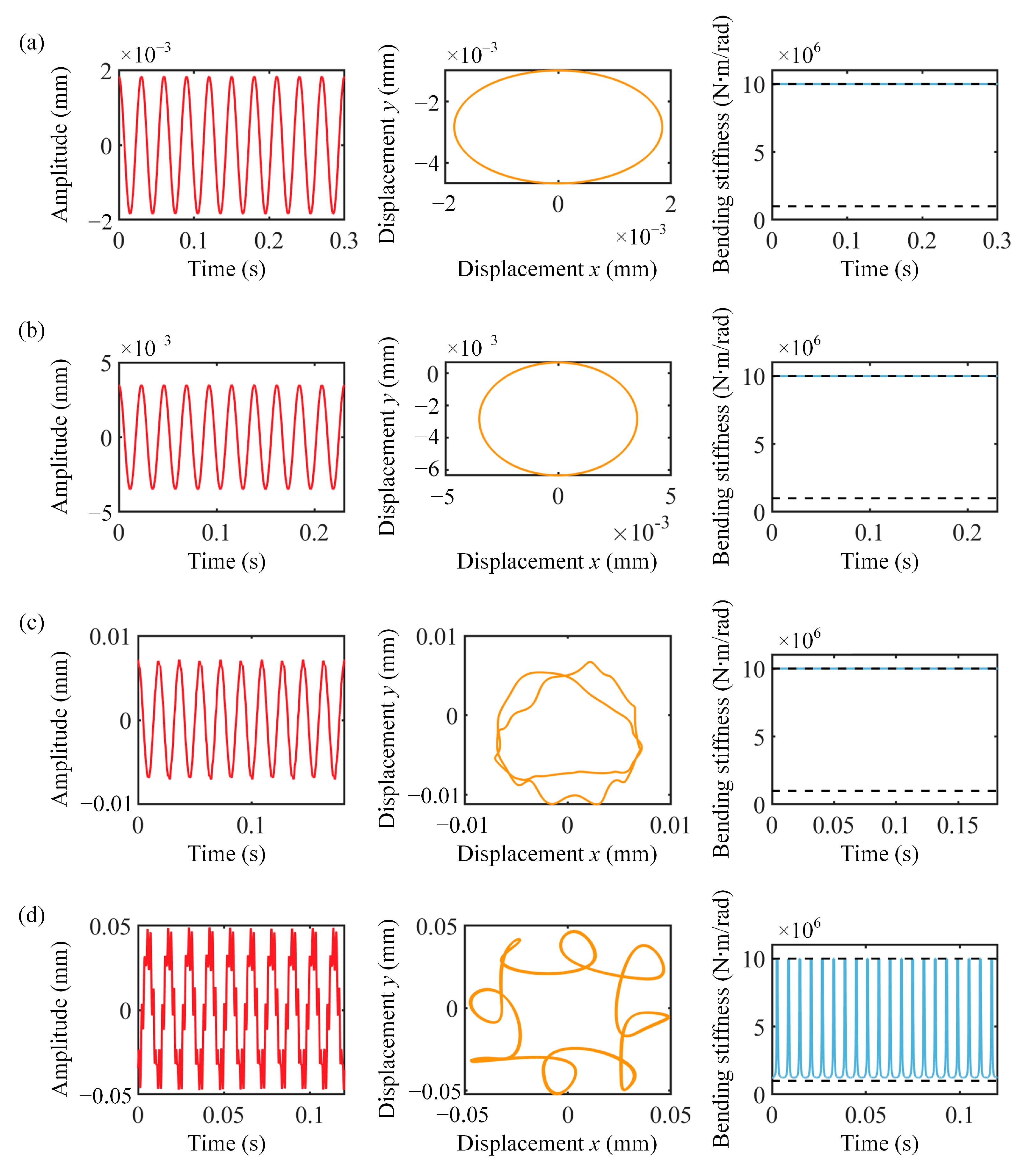
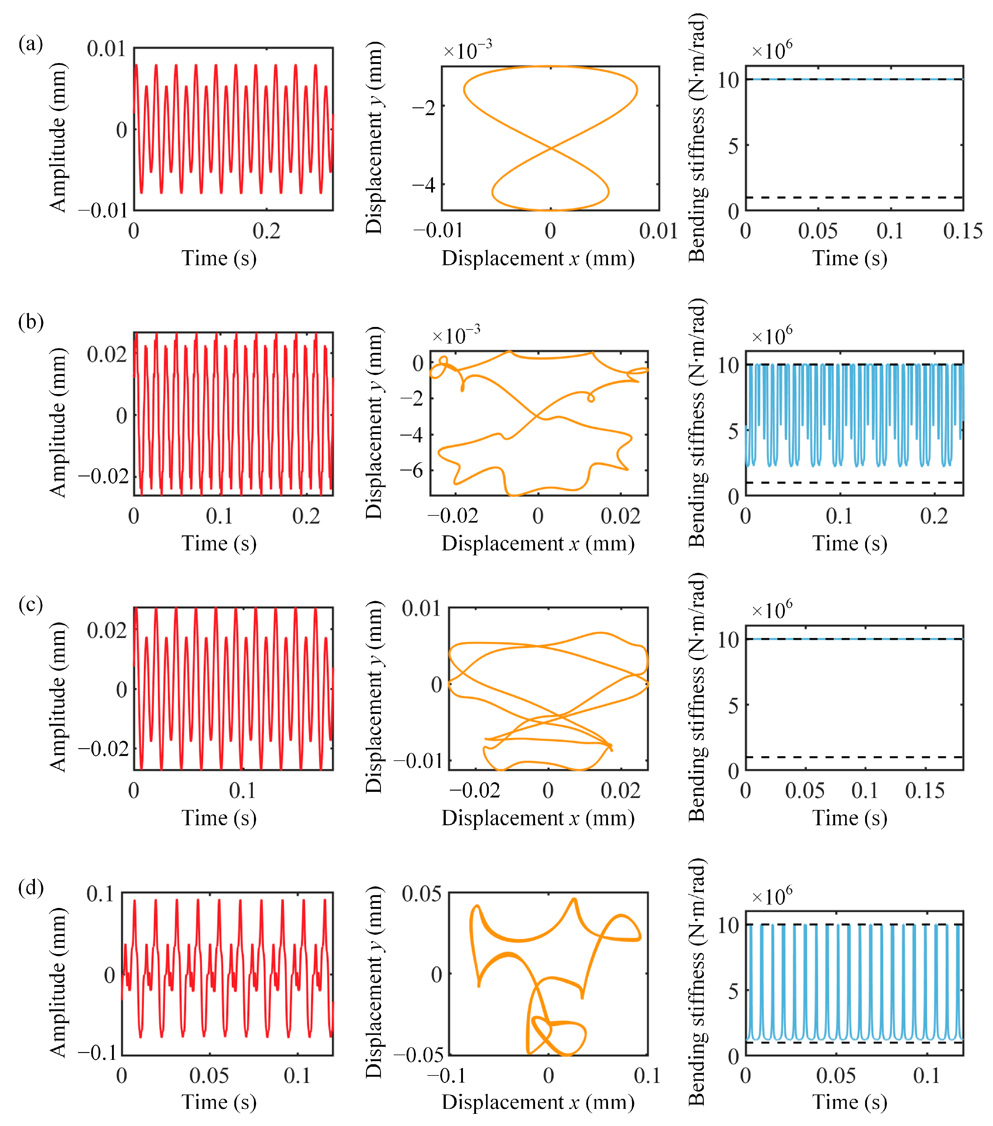
To further examine the effect of misalignment on the vibration response of the BJRS, Figure 4 and Figure 5 illustrate the time waveform, rotor orbit, and bending stiffness without and with misalignment conditions, respectively. A comparison of Figure 4 and Figure 5 reveals that the presence of misalignment causes the rotor orbits to exhibit an ‘8’ shape. Furthermore, the presence of misalignment results in a reduction in bending stiffness when operating at 2× frequency resonance speed. Some bending-stiffness curves for the cases without and with misalignment exhibit similar patterns because both cases employ the same two-stage bending-stiffness model and follow the same stiffness-switching mechanism between the two stages.

3.2. Effect of Misalignment Degree

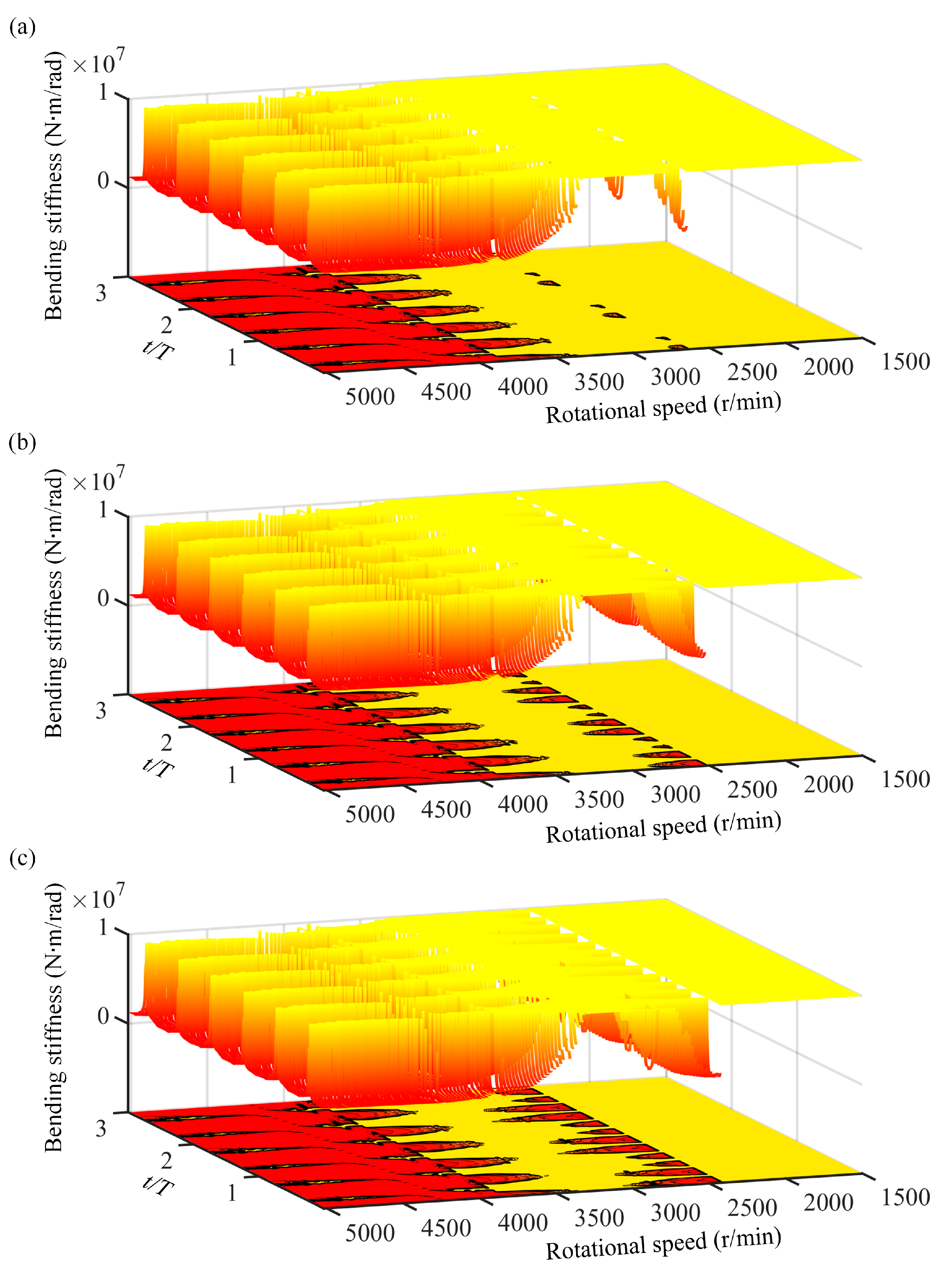
The impact of misalignment degree on the dynamics of the BJRS is studied in this subsection. Figure 6 depicts the time-varying stiffness when the misalignment distances are 1, 4, and 7 mm. As the degree of misalignment increases, it becomes apparent that the reduction in bending stiffness grows more pronounced. This phenomenon occurs because as the degree of misalignment increases, nonlinear forces grow correspondingly; this, in turn, amplifies the decline in the joint interface’s bending stiffness.
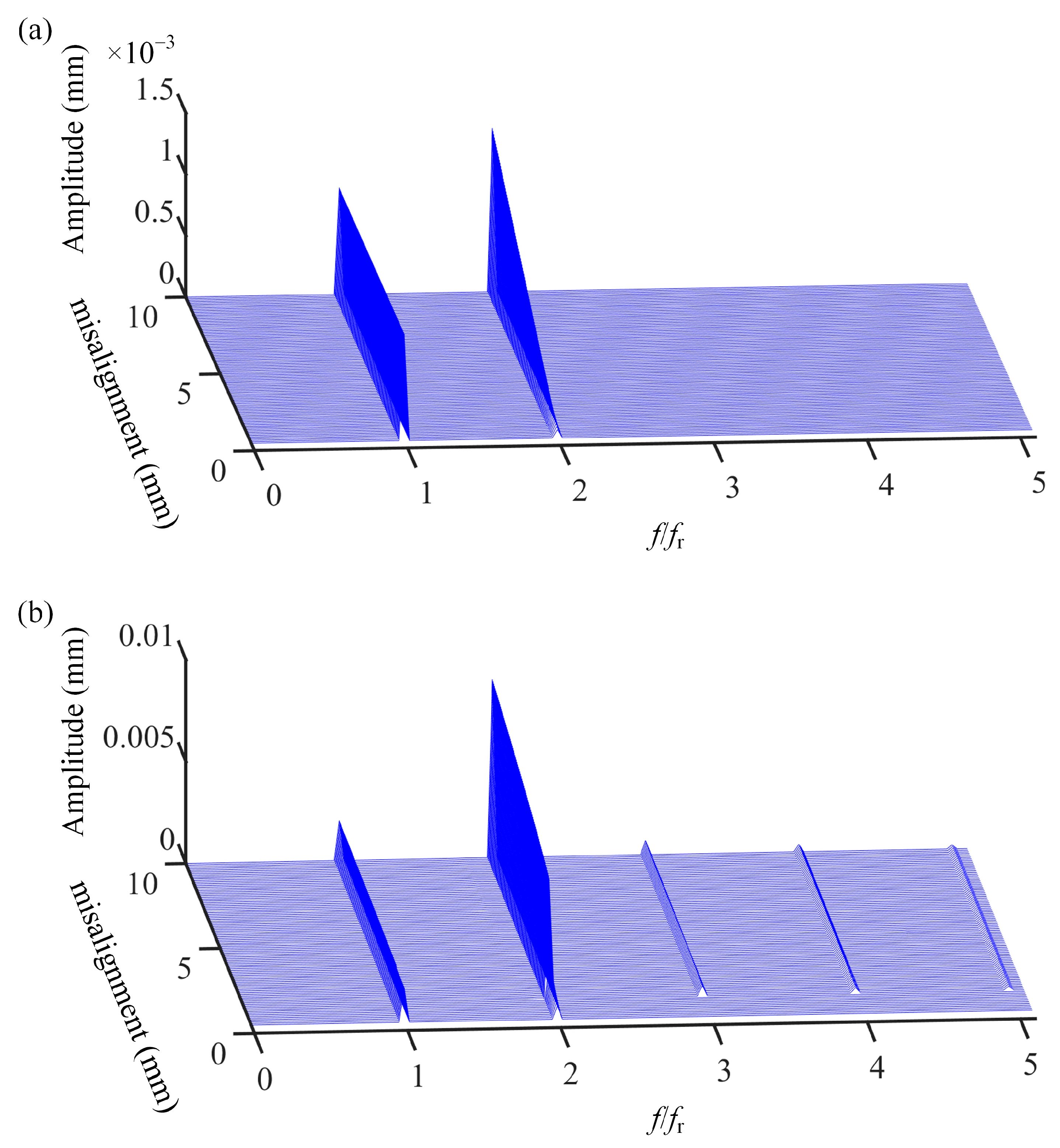
As shown in Figure 6, the color transition from yellow to red reflects a decrease in bending stiffness, with the corresponding values indicated by the vertical axis. The spectrum diagrams under different misalignment degrees are illustrated in Figure 7. From Figure 7a, it is observed that at 2000 r/min (a non-resonant speed), the 2× frequency increases linearly as the degree of misalignment rises. In contrast, at the 2× resonant speed (2600 r/min), as the degree of misalignment increases, the 2× component experiences a sudden surge, and multiple harmonic components also appear simultaneously (see Figure 7b). The underlying mechanism is that at the 2× frequency resonance speed, the gradually increasing misalignment force leads to a reduction in bending stiffness, thereby causing a sudden increase in the 2× frequency.
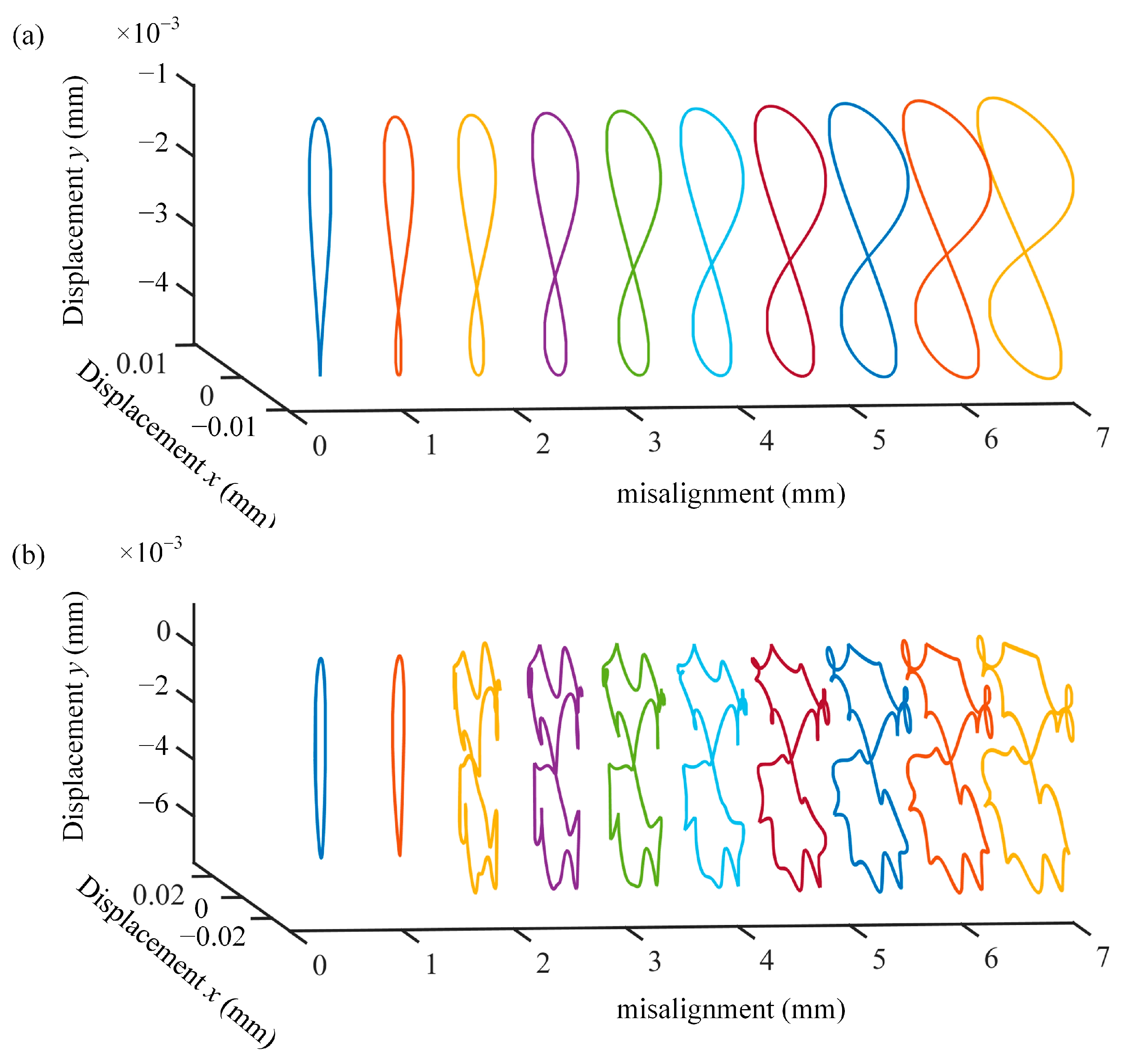
Figure 8a and Figure 8b respectively show the rotor orbits at 2000 r/min and 2600 r/min under different misalignment degrees, which are distinguished by different colors. For the non-resonant speed (see Figure 8a), the rotor orbit gradually changes from a circle to an ‘8’ shape. As for the 2× frequency resonance speed, the rotor orbit suddenly changes from a circle to a complex ‘8’ shape.

4. Experimental Study

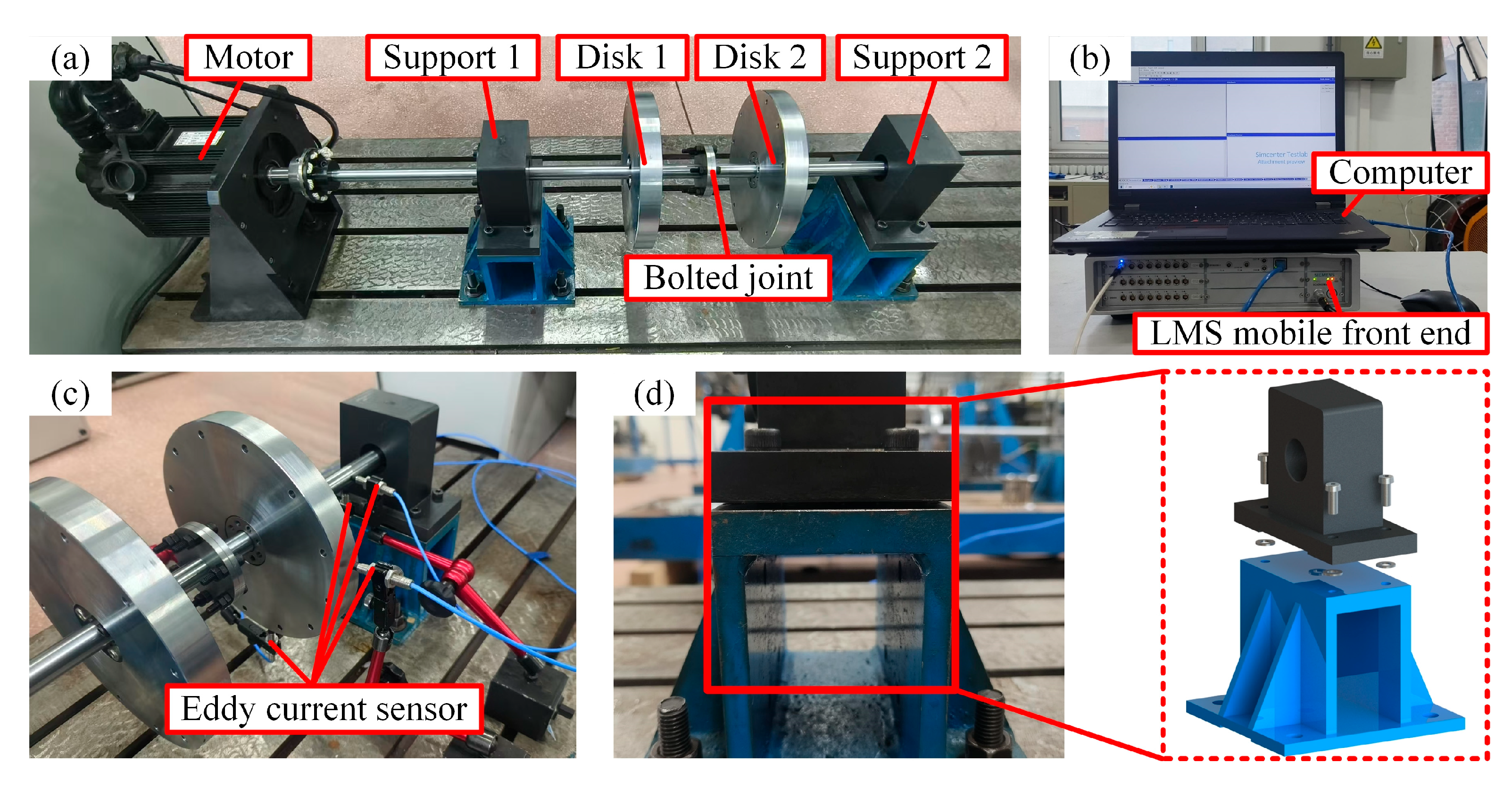
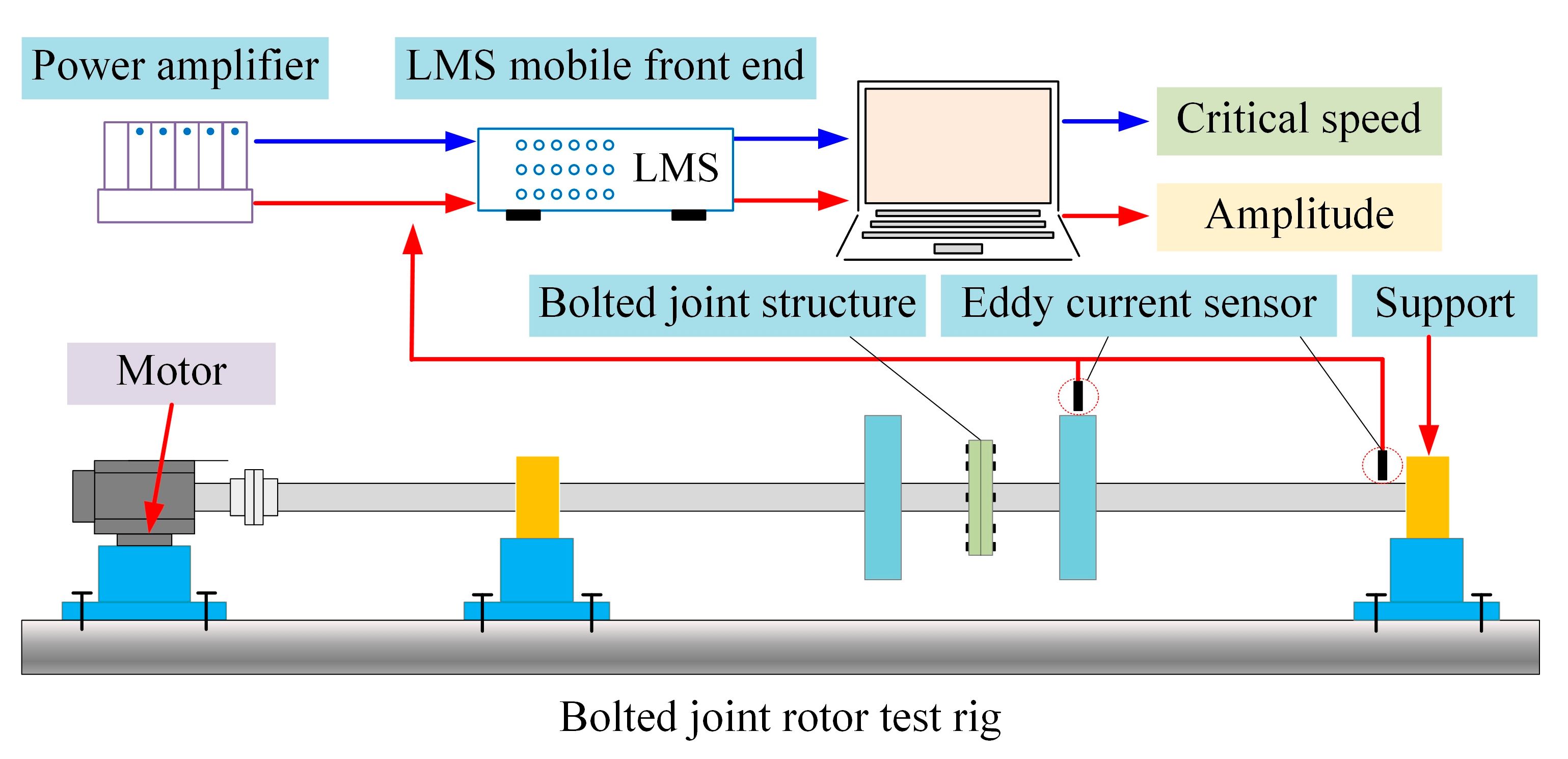
To validate certain typical dynamics of a BJRS affected by misalignment, an experimental setup incorporating a misaligned BJRS configuration is established, as depicted in Figure 9a. The vibration signals are captured utilizing eddy current sensors and an LMS mobile front end (see Figure 9b,c). A misalignment fault can be simulated by installing shims at the bottom of the bearing pedestal (see Figure 9d). The entire process of data collection and analysis for the experiment is illustrated in Figure 10. The same FFT procedure is applied to the measured vibration signals to extract the frequency components. The experimental critical speed and the 2× resonance speed are identified from the peaks of the corresponding 1× and 2× response amplitudes, respectively.
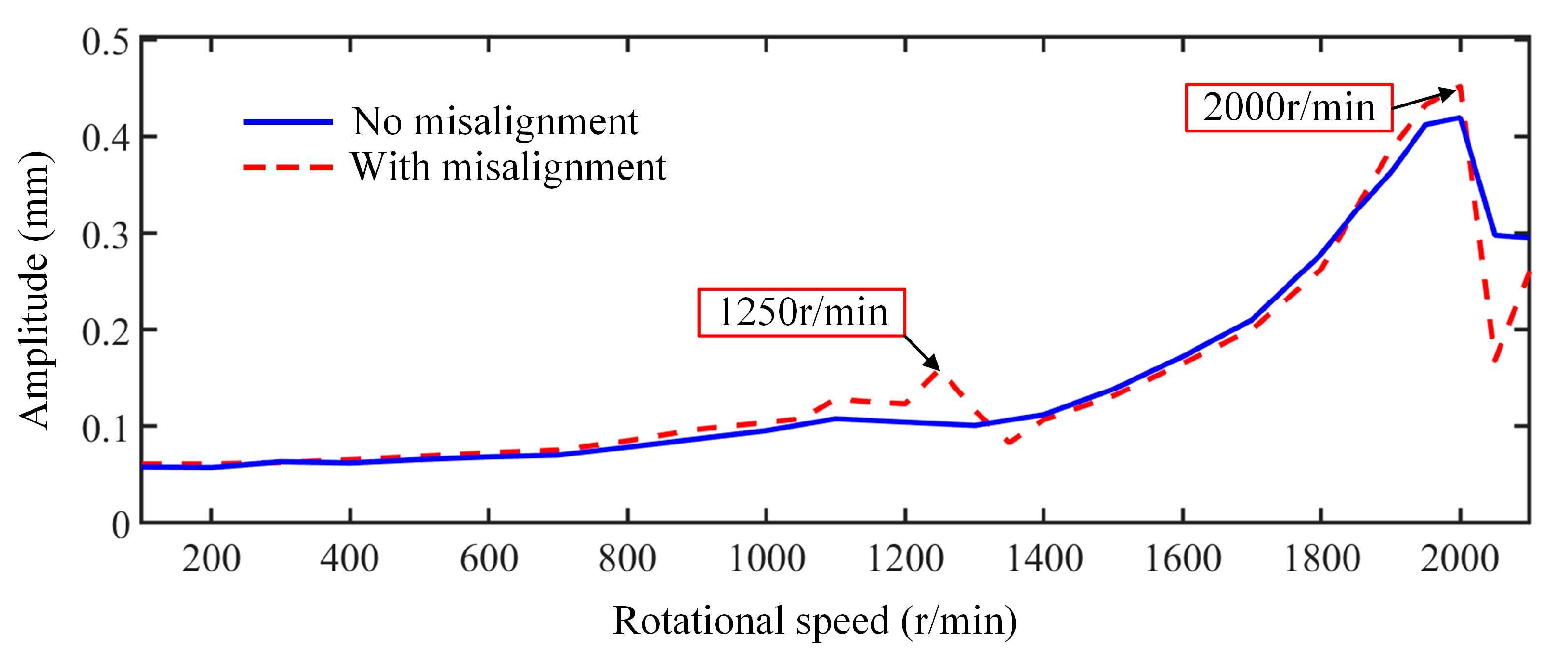
Figure 11 illustrates the vibration responses versus speeds of rotor test rigs with and without misalignment faults. The critical speed (1× frequency resonance) is 2000 r/min, and 2× frequency resonance speed is 1250 r/min. The 2× frequency resonance speed is greater than 0.5ωn, which aligns well with the numerical outcomes, verifying the dynamic model and phenomena.
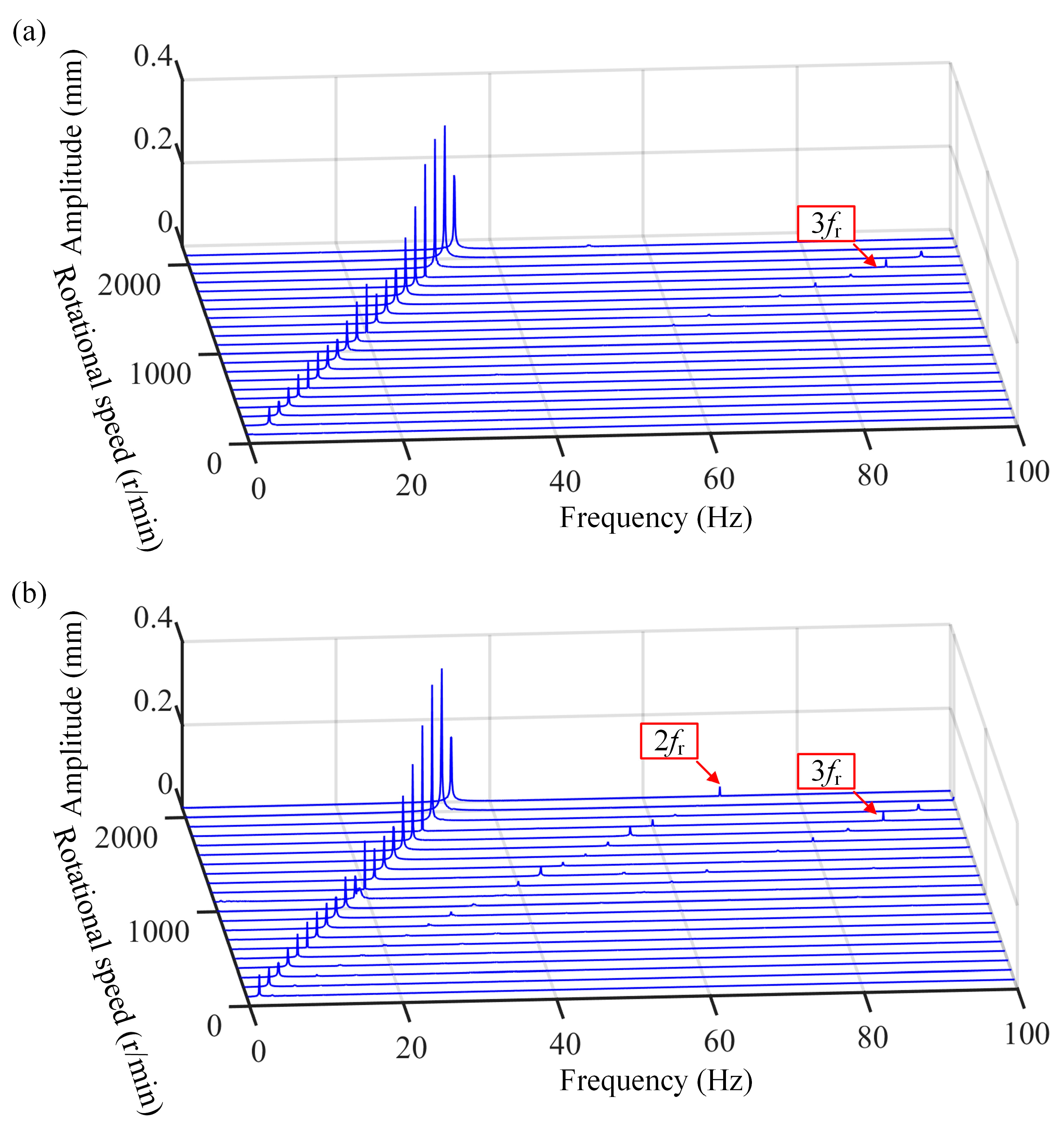
The spectrum cascades with and without misalignment faults are shown in Figure 12. It can be seen that when a misalignment fault occurs in the coupling, the 2× frequency component is clearly visible in Figure 12b.
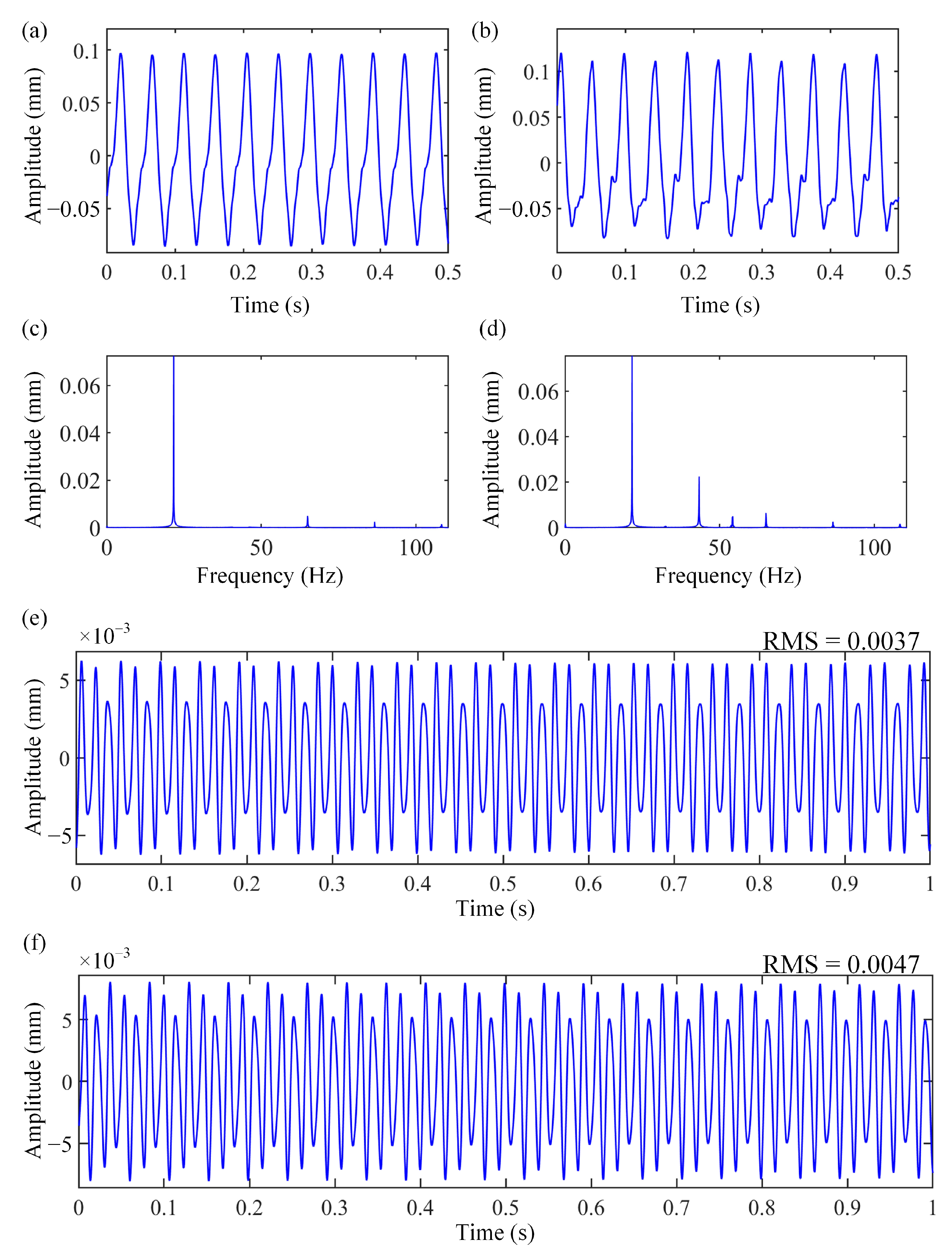
Moreover, Figure 13 illustrates the vibration response in time domain with and without misalignment faults, at 2× frequency resonance speed (1250 r/min). From Figure 13c,d, a distinct 2× frequency appears when misalignment fault occurs. To further verify the influence of misalignment faults on rotor system, RMS (root mean square) responses of 3× and 5× frequency with and without misalignment faults are obtained through filtering processing, as shown in Figure 13e,f. When a misalignment fault occurs, the RMS value increases from 0.0037 to 0.0047. This indicates that the misalignment fault exacerbates the loss of bending stiffness, thereby validating the patterns revealed by the numerical analysis.

5. Conclusions

This work constructs a mathematical model of the BJRS with misalignment fault. Through numerical analyses and experimental verification, we investigate the interaction mechanism between bolted joints and misalignment faults. Several distinctive vibration phenomena are observed, which can be used to identify whether a bolted joint rotor system has experienced misalignment faults and a loss of bending stiffness. The primary findings can be summarized as follows:
  • The 2× frequency resonance speed does not equate precisely to 0.5 times the critical speed; instead, it is found to be higher than this value. This phenomenon occurs because the degree of stiffness reduction varies between the critical speed and the 2× frequency resonance speed, which leads to the 2× frequency resonance speed being higher than 0.5ωn.
  • The presence of misalignment faults results in a more complex frequency spectrum, and the range of rotational speeds exhibiting such complex frequency components expands.
  • Misalignment faults intensify the bending stiffness loss phenomenon, and the rotational speed range affected by such stiffness loss expands.
  • As the degree of misalignment increases, the bending stiffness loss phenomenon intensifies. At the rotational speeds where stiffness loss occurs, the amplitude of 2× frequency undergoes a sudden change with the emergence of higher-order harmonic components. Concurrently, the rotor orbits also exhibit a sudden change. In contrast, at rotational speeds where no bending stiffness loss occurs, the amplitude of 2× frequency increases gradually and consistently, and the rotor orbits evolve in a smooth and continuous manner.

Author Contributions

Conceptualization, L.L.; methodology, L.L.; software, L.L., F.X. and F.L.; validation, L.L., F.X. and F.L.; formal analysis, B.Z.; investigation, L.L. and F.X.; data curation, B.Z. and F.L.; writing—original draft preparation, L.L.; writing—review and editing, B.Z.; visualization, F.X. and F.L.; funding acquisition, L.L. All authors have read and agreed to the published version of the manuscript.

Funding

This work was supported by National Natural Science Foundation of China, grant numbers 52405095; Guangdong Basic and Applied Basic Research Foundation, grant number 2023A1515110557; and the Fundamental Research Funds for the Central Universities of China, grant numbers N2403022.

Data Availability Statement

The original contributions presented in this study are included in the article. Further inquiries can be directed to the corresponding author.

Conflicts of Interest

The authors declare no conflicts of interest.

References

  1. Li, Y.; Zhu, Z.; Liu, K.; Luo, Z.; Wen, C.; Wu, W. Dynamic modelling and vibration analysis of a bolted spigot joint structure considering mating interface friction: Simulation and experiment. Nonlinear. Dyn. 2024, 112, 7977–8000. [Google Scholar] [CrossRef] [Scilit]
  2. Wang, N.; Jiang, D. Vibration response characteristics of a dual-rotor with unbalance-misalignment coupling faults: Theoretical analysis and experimental study. Mech. Mach. Theory 2018, 125, 207–219. [Google Scholar] [CrossRef] [Scilit]
  3. Li, L.; Luo, Z.; Wu, F.; He, F.; Sun, K. Experimental and numerical studies on partial similitude of rotor system considering the vibration consistency. Mech. Mach. Theory 2023, 183, 105270. [Google Scholar] [CrossRef] [Scilit]
  4. Liu, S.; Ma, Y.; Zhang, D.; Hong, J. Studies on dynamic characteristics of the joint in the aero-engine rotor system. Mech. Syst. Signal Process. 2012, 29, 120–136. [Google Scholar] [CrossRef] [Scilit]
  5. Lin, Q.; Zhao, Y.; Sun, Q.; Chen, K. Reliability evaluation method of anti-loosening performance of bolted joints. Mech. Syst. Signal Process. 2022, 162, 108067. [Google Scholar] [CrossRef] [Scilit]
  6. Yang, H.; Li, D.; Sun, J.; Xu, C. Multiscale modeling of friction hysteresis at bolted joint interfaces. Int. J. Mech. Sci. 2024, 282, 109586. [Google Scholar] [CrossRef] [Scilit]
  7. Sun, J.; Yang, H.; Li, D.; Xu, C. Experimental investigation on acoustic emission in fretting friction and wear of bolted joints. J. Sound Vib. 2023, 558, 117773. [Google Scholar] [CrossRef] [Scilit]
  8. Li, D.; Botto, D.; Li, R.; Xu, C.; Zhang, W. Experimental and theoretical studies on friction contact of bolted joint interfaces. Int. J. Mech. Sci. 2022, 236, 107773. [Google Scholar] [CrossRef] [Scilit]
  9. Estakhraji, S.; Allen, M. Extension of the Harmonic Balance Method for dynamic systems with Iwan joints. Mech. Syst. Signal Process. 2022, 166, 108434. [Google Scholar] [CrossRef] [Scilit]
  10. Li, Z.; Zhang, Y.; Li, C.; Xu, M.; Dai, W.; Liu, Z. Modeling and nonlinear dynamic analysis of bolt joints considering fractal surfaces. Nonlinear. Dyn. 2022, 108, 1071–1099. [Google Scholar] [CrossRef] [Scilit]
  11. Liu, J.; Ouyang, H.; Feng, Z.; Cai, Z.; Mo, J.; Peng, J.; Zhu, M. Dynamic behaviour of a bolted joint subjected to torsional excitation. Tribol. Int. 2019, 140, 105877. [Google Scholar] [CrossRef] [Scilit]
  12. Dreher, T.; Brake, M.; Seeger, B.; Krack, M. In situ, real-time measurements of contact pressure internal to jointed interfaces during dynamic excitation of an assembled structure. Mech. Syst. Signal Process. 2021, 160, 107859. [Google Scholar] [CrossRef] [Scilit]
  13. Mir-Haidari, S.; Behdinan, K. Nonlinear effects of bolted flange connections in aeroengine casing assemblies. Mech. Syst. Signal Process. 2022, 166, 108433. [Google Scholar] [CrossRef] [Scilit]
  14. Yang, Z.; Yang, L.; Sun, Y.; Chen, X. A novel contact-aided continuum robotic system: Design, modeling, and validation. IEEE Trans. Robot. 2024, 40, 3024–3043. [Google Scholar] [CrossRef] [Scilit]
  15. Li, L.; Luo, Z.; He, F.; Zhou, J.; Ma, H.; Li, H. Experimental and simulation studies on similitude design method for shock responses of beam-plate coupled structure. Appl. Math. Mech. Engl. 2023, 44, 917–930. [Google Scholar] [CrossRef]
  16. Jamia, N.; Jalali, H.; Taghipour, J.; Friswell, M.; Khodaparast, H. An equivalent model of a nonlinear bolted flange joint. Mech. Syst. Signal Process. 2021, 153, 107507. [Google Scholar] [CrossRef] [Scilit]
  17. Balaji, N.; Dreher, T.; Krack, M.; Brake, M. Reduced order modeling for the dynamics of jointed structures through hyper-reduced interface representation. Mech. Syst. Signal Process. 2021, 149, 107249. [Google Scholar] [CrossRef] [Scilit]
  18. Yang, L.; Luo, X.; Yang, Z.; Nan, C.; Chen, X.; Sun, Y. FE reduced-order model-informed neural operator for structural dynamic response prediction. Neural Netw. 2025, 188, 107437. [Google Scholar] [CrossRef] [Scilit] [PubMed]
  19. Yuan, P.; Ren, W.; Zhang, J. Dynamic tests and model updating of nonlinear beam structures with bolted joints. Mech. Syst. Signal Process. 2019, 126, 193–210. [Google Scholar] [CrossRef] [Scilit]
  20. Yin, T.; Wang, X.; Zhu, H. A probabilistic approach for the detection of bolt loosening in periodically supported structures endowed with bolted flange joints. Mech. Syst. Signal Process. 2019, 128, 588–616. [Google Scholar] [CrossRef] [Scilit]
  21. Shu, Z.; Li, Z.; Yu, X.; Zhang, J.; He, M. Rotational performance of glulam bolted joints: Experimental investigation and analytical approach. Constr. Build. Mater. 2019, 213, 675–695. [Google Scholar] [CrossRef] [Scilit]
  22. Beaudoin, M.; Behdinan, K. Analytical lump model for the nonlinear dynamic response of bolted flanges in aero-engine casings. Mech. Syst. Signal Process. 2019, 115, 14–28. [Google Scholar] [CrossRef] [Scilit]
  23. Du, F.; Tian, Z.; Nan, Y.; Zhang, X.; Xu, C.; Wang, S.; Su, Z. A modified virtual time reversal method for enhancing monitoring sensitivity of bolt preloads based on ultrasonic guided waves. J. Sound. Vib. 2024, 585, 118475. [Google Scholar] [CrossRef] [Scilit]
  24. Li, Y.; Wen, C.; Luo, Z.; Jin, L. Bifurcation studies of a bolted-joint rotor system subjected to fixed-point rubbing fault. Nonlinear. Dyn. 2022, 110, 3045–3073. [Google Scholar] [CrossRef] [Scilit]
  25. Li, Y.; Yang, B.; Wen, C. Stability analysis of the bending-torsional vibration of a bolted joint rotor-bearing-support system. Nonlinear. Dyn. 2025, 113, 28757–28786. [Google Scholar] [CrossRef] [Scilit]
  26. Pirdayr, A.; Mohammadi, M.; Kazemzadeh-Parsi, M.; Rajabi, M. Self-loosening effects on vibration characteristics of plates with bolted joints: An experimental and finite element analysis. Measurement 2021, 185, 109922. [Google Scholar] [CrossRef] [Scilit]
  27. Li, L.; Luo, Z.; Wu, F.; He, F.; Sun, K. Frequency spectrum analysis of the rotor system with bolted joint: Numerical and experimental verification. Appl. Math. Model. 2023, 118, 745–761. [Google Scholar] [CrossRef] [Scilit]
  28. Du, D.; Sun, W.; Cui, B.; Liu, H.; Ma, H.; Liu, X.; Li, H. Traveling-wave vibrations of disc-drum rotors with PSC under mistuning-coupled conditions. Int. J. Mech. Sci. 2023, 250, 108326. [Google Scholar] [CrossRef] [Scilit]
  29. Xiao, S.; Yu, P.; Jiang, Z.; Wang, C.; Chen, J. Nonlinear Modeling and Vibration Response Analysis of a Dual-Rotor System with an Inter-Shaft Graphite Seal. Mathematics 2024, 12, 454. [Google Scholar] [CrossRef] [Scilit]
  30. Zhang, Y.; Liu, S.; Xiang, L.; Hu, A. Dynamic analysis of a multi-disk rod fastening rotor system with rub-impact based on multiple parameters. Nonlinear. Dyn. 2022, 107, 2133–2152. [Google Scholar] [CrossRef] [Scilit]
  31. Zhou, Y.; Zhou, J.; Wang, Y.; Zhang, Y.; Xu, Y.; Lin, Z. Investigations on the modal vibration caused by bolted joint interface contact in the rotor-AMBs systems: Modelling and experimentation. Appl. Math. Model. 2024, 134, 249–267. [Google Scholar] [CrossRef] [Scilit]
  32. Cui, Y.; Wang, Y. Effective contact stiffness model for bolted flange joint with spigot. Int. J. Mech. Sci. 2025, 293, 110213. [Google Scholar] [CrossRef] [Scilit]
  33. Li, J.; Yang, Z.; Ren, Q.; Mo, G.; Zhong, W.; Feng, Y.; Li, G. Study on the bistable vibration behaviour of a rod-fastened rotor-bearing system. Nonlinear. Dyn. 2022, 109, 609–629. [Google Scholar] [CrossRef] [Scilit] [PubMed]
  34. Liu, X.; Huang, K.; Han, X.; Liang, D.; Wang, X.; Zhang, L.; Guo, L. Temperature effect on the fatigue properties of CFRP bolted joints by combining DIC, AE and IRT techniques. Thin. Wall. Struct. 2025, 215, 113522. [Google Scholar] [CrossRef] [Scilit]
  35. Zhai, Y.; Qu, H.; Li, D.; Ge, E.; Xiao, R.; Yang, J. Effect of bolt preload uncertainty on fatigue reliability of single-lap, countersunk composite bolted joints considering forced assembly interaction. Int. J. Fatigue 2025, 198, 109017. [Google Scholar] [CrossRef] [Scilit]
  36. Chen, W.; Liu, Z.; Zhao, Y.; Yan, X.; Li, M.; Li, Y. Tangential stiffness modeling and multi-stage analysis of single-lap double-bolted joints based on spring coupling element method. Structures 2025, 79, 109610. [Google Scholar] [CrossRef] [Scilit]
  37. Yu, P.; Li, L.; Chen, G.; Yang, M. Dynamic modelling and vibration characteristics analysis for the bolted joint with spigot in the rotor system. Appl. Math. Model. 2021, 94, 306–331. [Google Scholar] [CrossRef] [Scilit]
  38. Hong, J.; Yang, Z.; Wang, Y.; Cheng, R.; Ma, Y. Combination resonances of rotor systems with asymmetric residual preloads in bolted joints. Mech. Syst. Signal Process. 2023, 183, 109626. [Google Scholar] [CrossRef] [Scilit]
  39. Han, Z.; Wang, D.; Wang, Y.; Hong, J.; Cheng, R. Dynamic effects of the initial skewness of the inertial principal axis on the rotor with bolted joint. Mech. Syst. Signal Process. 2023, 200, 110564. [Google Scholar] [CrossRef] [Scilit]
  40. Li, L.; Luo, Z.; He, F.; Qin, Z.; Li, Y.; Yan, X. Similitude for the Dynamic Characteristics of Dual-Rotor System with Bolted Joints. Mathematics 2022, 10, 3. [Google Scholar] [CrossRef] [Scilit]
  41. Li, L.; Luo, Z.; He, F.; Ding, Z.; Sun, K. A partial similitude method for vibration responses of rotor systems: Numerical and experimental verification. Int. J. Mech. Sci. 2021, 208, 106696. [Google Scholar] [CrossRef] [Scilit]
  42. Tuckmantel, F.; Cavalca, L. Vibration signatures of a rotor-coupling-bearing system under angular misalignment. Mech. Mach. Theory 2019, 133, 559–583. [Google Scholar] [CrossRef] [Scilit]
  43. Lu, K.; Jin, Y.; Huang, P.; Zhang, F.; Zhang, H.; Fu, C.; Chen, Y. The applications of POD method in dual rotor-bearing systems with coupling misalignment. Mech. Syst. Signal Process. 2021, 150, 107236. [Google Scholar] [CrossRef] [Scilit]
  44. Wang, Z.; Sun, R.; Liu, Y.; Yao, Y.; Tian, J. Analysis of Nonlinear Vibration Characteristics and Whirl Behavior of Dual-Rotor Systems with Inter-Shaft Rub Impact. Mathematics 2024, 12, 1436. [Google Scholar] [CrossRef] [Scilit]
  45. Kumar, P.; Tiwari, R. Finite element modelling, analysis and identification using novel trial misalignment approach in an unbalanced and misaligned flexible rotor system levitated by active magnetic bearings. Mech. Syst. Signal Process. 2021, 152, 107454. [Google Scholar] [CrossRef] [Scilit]
  46. Wang, P.; Xu, H.; Ma, H.; Han, H.; Yang, Y. Effects of three types of bearing misalignments on dynamic characteristics of planetary gear set-rotor system. Mech. Syst. Signal Process. 2022, 169, 108736. [Google Scholar] [CrossRef] [Scilit]
  47. Wang, P.; Xu, H.; Yang, Y.; Ma, H.; He, D.; Zhao, X. Dynamic characteristics of ball bearing-coupling-rotor system with angular misalignment fault. Nonlinear. Dyn. 2022, 108, 3391–3415. [Google Scholar] [CrossRef] [Scilit]
  48. Tang, H.; Ren, Y.; Xiang, J.; Kumar, A. Numerical and experimental analysis of rotor-bearing system for axial piston pump with misalignment–rubbing coupling fault. J. Sound. Vib. 2023, 559, 117786. [Google Scholar] [CrossRef] [Scilit]
  49. Miao, X.; He, J.; Jiang, D.; Zhang, D.; Pennacchi, P.; Fei, Q. Research on nonlinear vibration of a dual-rotor system with combined misalignment of cylindrical roller bearing and coupling. Nonlinear. Dyn. 2025, 113, 3147–3170. [Google Scholar] [CrossRef] [Scilit]
  50. Xu, H.; Yang, Y.; Ma, H.; Luo, Z.; Li, X.; Han, Q.; Wen, B. Vibration characteristics of bearing-rotor systems with inner ring dynamic misalignment. Int. J. Mech. Sci. 2022, 230, 107536. [Google Scholar] [CrossRef] [Scilit]
  51. Li, X.; Xu, Y.; Liu, J.; Zhang, Y.; Liu, J.; Pan, G.; Shi, Z. Vibration analysis of the propulsion shaft system considering dynamic misalignment in the outer ring. J. Sound. Vib. 2024, 589, 118612. [Google Scholar] [CrossRef] [Scilit]
  52. Guan, H.; Wang, P.; Xiong, Q.; Ma, H.; Zhou, S.; Mu, Q.; Zeng, Y.; Chen, Y. Modeling of misaligned bearing induced by coupling misalignment and assembly errors and vibration analysis in dual-rotor system. Mech. Syst. Signal Process. 2025, 230, 112656. [Google Scholar] [CrossRef] [Scilit]
  53. Li, L.; Ma, T.; Luo, Z.; Gao, D.; Ge, X.; Ma, H.; Wang, S. A novel scaling method for the elastic ring supporting structure of an aero-engine rotor system: Analytical and experimental investigations. Appl. Math. Mech. Engl. 2026, 47, 1–18. [Google Scholar] [CrossRef] [Scilit]
  54. Qin, Z.; Qin, L.; Zhu, Q.; Wang, P.; Zhang, F.; Chu, F. An ultrasensitive self-powered smart bearing pedestal with fault locating capability. Mech. Syst. Signal Process. 2025, 235, 112924. [Google Scholar] [CrossRef] [Scilit]
  55. Li, L.; Ma, T.; Liang, F.; Xie, F. Nonlinear dynamic modeling of rotor-bearing systems with combined support considering coupled motion: Numerical and experimental studies. Mathematics 2025, 13, 3694. [Google Scholar] [CrossRef] [Scilit]
  56. Chen, R.; Lv, J.; Tian, J.; Ai, Y.; Zhang, F.; Yao, Y. Modeling and nonlinear dynamic characteristics analysis of fault bearing time-varying stiffness-flexible rotor coupling system. Mathematics 2024, 12, 3591. [Google Scholar] [CrossRef] [Scilit]
  57. Li, X.; Li, S.; Zhang, G.; Xie, Y.; Wang, T.; Chu, F. A novel interpretable dynamic weighted domain adaptation network for cross-domain fault diagnosis of bearings under time-varying speeds. Eng. Appl. Artif. Intell. 2026, 170, 114173. [Google Scholar] [CrossRef] [Scilit]
  58. Li, X.; Wu, X.; Yu, J.; Wang, T.; Shi, C.; Choi, J.-H.; Chu, F. A fault diagnosis data augmentation method integrating multimodal non-Gaussian denoising diffusion generative adversarial network. Adv. Eng. Inform. 2025, 68, 103776. [Google Scholar] [CrossRef] [Scilit]
  59. Li, X.; Li, G.; Wang, T.; Dong, Z.; Qin, Z.; Chu, F. Knowledge extraction and retrieval-augmented generation for intelligent maintenance of wind power equipment based on graph attention networks. Chin. J. Mech. Eng. 2025, 38, 100141. [Google Scholar] [CrossRef] [Scilit]
  60. Li, X.; Ran, G.; Xiao, S.; Su, K.; Li, Q.; Wang, T.; Qin, Z.; Chu, F. A fault diagnosis method for bearings based on multiscale graph convolutional network under non-stationary speed conditions. Mech. Mach. Theory 2025, 217, 106267. [Google Scholar] [CrossRef] [Scilit]
  61. Li, L.; Luo, Z.; Liu, K.; Zhou, J. Dynamic stiffness characteristics of aero-engine elastic support structure and its effects on rotor systems: Mechanism and numerical and experimental studies. Appl. Math. Mech. Engl. 2023, 44, 221–236. [Google Scholar] [CrossRef] [Scilit]
  62. Li, L.; Luo, Z.; He, F.; Sun, K.; Yan, X. An improved partial similitude method for dynamic characteristic of rotor systems based on Levenberg–Marquardt method. Mech. Syst. Signal Process. 2022, 165, 108405. [Google Scholar] [CrossRef] [Scilit]
  63. Li, Y.; Long, T.; Wu, W.; Wen, C.; Zhu, Z. Vibration characteristics of a bolted joint rotor-bearing system with rubbing and pedestal looseness coupled fault: Simulation and experiment. Appl. Math. Model. 2024, 132, 402–427. [Google Scholar] [CrossRef] [Scilit]
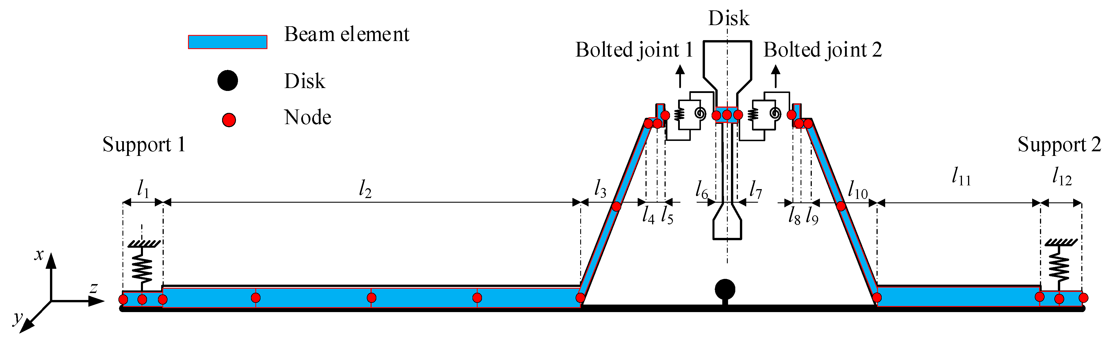
Figure 1. Sketch of the dynamic model of the BJRS.
Mathematics 14 02368 g001
Figure 2. Dynamics modeling and solution process of the BJRS.
Mathematics 14 02368 g002
Figure 3. (a) The amplitude frequency response of the BJRS. (b) The spectrum diagram without misalignment fault. (c) The spectrum diagram with misalignment fault. (d) The variation in bending stiffness without misalignment fault. (e) The variation in bending stiffness with misalignment fault.
Mathematics 14 02368 g003
Figure 4. The vibration responses of the BJRS without misalignment fault over a range of rotor speeds. (a) 2000 r/min. (b) 2600 r/min (2× frequency resonance speed). (c) 3300 r/min. (d) 5000 r/min.
Mathematics 14 02368 g004
Figure 5. The vibration responses of the BJRS with misalignment fault over different speed conditions. (a) 2000 r/min. (b) 2600 r/min (2× frequency resonance speed). (c) 3300 r/min. (d) 5000 r/min.
Mathematics 14 02368 g005
Figure 6. The variation in bending stiffness under different misalignment degrees. (a) 1 mm. (b) 4 mm. (c) 7 mm.
Mathematics 14 02368 g006
Figure 7. Spectrum diagrams under different misalignment degrees and different rotational speeds. (a) 2000 r/min (non-resonant speed). (b) 2600 r/min (2× frequency resonance speed).
Mathematics 14 02368 g007
Figure 8. Rotor orbits under different misalignment degrees and different rotational speeds. (a) 2000 r/min (non-resonant speed). (b) 2600 r/min (2× frequency resonance speed).
Mathematics 14 02368 g008
Figure 9. (a) The experimental rotor platform with misalignment. (b) Signal acquisition system. (c) Vibration pickup position. (d) Misalignment fault design.
Mathematics 14 02368 g009
Figure 10. Schematic diagram of experimental data collection and analysis.
Mathematics 14 02368 g010
Figure 11. Vibration responses versus speeds of rotor test rig with and without misalignment faults.
Mathematics 14 02368 g011
Figure 12. Spectrum cascades of the rotor test rig with and without misalignment fault. (a) Without misalignment fault. (b) With misalignment fault.
Mathematics 14 02368 g012
Figure 13. Vibration response in time domain of the rotor test rig with and without misalignment fault. (a) Time waveform without misalignment. (b) Vibration waveform with misalignment. (c) Spectrum plot without misalignment. (d) Spectrum plot with misalignment. (e) RMS responses of 3× and 5× frequency without misalignment fault. (f) RMS responses of 3× and 5× frequency with misalignment fault.
Mathematics 14 02368 g013
Table 1. Physical parameters of the BJRS.
Physical ParameterValuePhysical ParameterValue
Mass of Disk md (kg)6.462Density of the shaft ρ (kg/m3)7800
Eccentricity of Disk e (mm)0.7Poisson ratio of shaft element v0.3
Right bearing damping coefficient cb (Ns/m)200Mass of coupling m0 (kg)1.2
Right support stiffness kbr (N/m)8 × 107Eccentricity of coupling Δe (mm)5
Left support stiffness kbl (N/m)1 × 108Lateral stiffness of the joint kt (N/m)1 × 107
Elastic modulus of the shaft E (GPa)210Bending stiffness of bolted joint kj1 (Nm/rad)1 × 107
Critical angle φ0 (rad)2 × 10⁻⁵Bending stiffness of bolted joint kj2 (Nm/rad)1 × 106
Table 2. The specific parameters of the shaft element.
Elements1~23~67~891011~12131415~161718~19
R/mm303335~15015017017017015035~1503330
r/mm000~1401401401401401400~14000
l/mm2560040736376030070
Disclaimer/Publisher’s Note: The statements, opinions and data contained in all publications are solely those of the individual author(s) and contributor(s) and not of MDPI and/or the editor(s). MDPI and/or the editor(s) disclaim responsibility for any injury to people or property resulting from any ideas, methods, instructions or products referred to in the content.