1. Introduction
In recent years, small flexible-wing aircraft have demonstrated significant potential for low-altitude urban missions due to their superior maneuverability and adaptability [
1]. However, their operation at low Reynolds numbers (typically on the order of 10
4 to 10
5) involves complex aerodynamic phenomena, and their lightweight, low-inertia nature makes them highly susceptible to atmospheric disturbances, particularly wind gusts, which critically compromise flight stability and structural integrity [
2,
3,
4,
5,
6,
7]. Consequently, developing effective gust alleviation techniques is paramount for the reliable deployment of this class of vehicles [
8,
9,
10,
11,
12,
13,
14,
15].
Gust alleviation strategies are broadly categorized as passive or active [
16]. Passive methods, such as exploiting composite anisotropy or structural tailoring, inherently improve aeroelastic response but lack adaptability to varying flight conditions [
17,
18,
19]. Active methods, in contrast, modify aerodynamic load distribution in real-time by actuating control surfaces, offering greater environmental adaptability and performance potential [
20]. Current research frontiers converge on two interrelated directions: innovations in aerodynamic configuration and evolution in control strategy.
Regarding aerodynamic configuration, actively controlled wingtip devices have become a focal point due to their ability to dramatically alter wing load distribution. Early investigations explored the potential of multi-flap systems like the Variable Camber Continuous Trailing Edge (VCCTE) [
21,
22,
23,
24,
25]. Similarly, the University of Washington designed the large flexible wing (LFW) wind-tunnel model with active trailing-edge flaps [
26,
27]. Recently, the focus has shifted toward more integrated and dynamically responsive wingtip designs. For instance, Healy et al. conducted an in-depth experimental and numerical study on the nonlinear dynamics of a flared folding wingtip (FFWT), revealing complex behaviors like limit cycle oscillations beyond the flutter boundary, and introduced active control via a wingtip trim tab [
28]. Ahmadi-Tehrani et al. directly addressed gust load alleviation through wind-tunnel tests of an active controlled folding wingtip (ACFWT), demonstrating its effectiveness using classical PD and PID control strategies [
29]. In parallel, other research has advanced the fundamental modeling of such devices. Recent work has developed a nonlinear aeroelastic framework coupling multibody dynamics with an Unsteady Vortex Lattice Method (UVLM) specifically for FFWTs, explicitly accounting for the geometric nonlinearities of large folding angles often neglected in linear analyses. This approach has been validated against wind-tunnel gust response tests, highlighting the significant influence of nonlinearities on the wingtip’s dynamic response, especially under low-frequency excitation [
30].
Concerning control strategies, research has evolved from classical to modern optimal and robust control. For novel configurations, Balatti et al. implemented a PD controller on a hinged wingtip in simulation [
31]. However, for a multivariable, strongly coupled flexible aircraft system, advanced strategies like model predictive control (MPC) have garnered significant attention due to their ability to explicitly handle constraints and perform multi-objective optimization. Narimani et al. applied MPC to an FFWT, optimizing the wing root bending moment over a prediction horizon and achieving superior gust load reduction compared to PID [
32]. Extending MPC to more complex, flexible airframes, recent work has demonstrated a practical framework for gust load alleviation on flexible flying wings. By employing a reduced-order linear parameter-varying (LPV) model and efficient optimization, it balances performance with computational tractability, showcasing the real-time potential of advanced control for complex aeroelastic systems [
33]. Nevertheless, algorithms like MPC demand considerable computational resources and accurate models, posing challenges for implementation on resource-constrained small platforms [
34,
35,
36].
In summary, while significant progress has been made in both aerodynamic configurations and control algorithms, a discernible gap remains: the lack of an integrated solution specifically designed for small, low-cost, resource-constrained flexible aircraft platforms that balances high performance with low computational complexity. Most advanced control studies target larger platforms or assume substantial computational capability, often overlooking the practical constraints of small aircraft.
To bridge this gap, the core contribution of this work lies in the novel integration of an AGAD at the wingtip with conventional tail-plane control within an LQR-ESO framework, tailored specifically for small flexible aircraft operating in gust-prone environments. This research employs an ESO to estimate the unmeasurable gust-induced angle of attack, enabling effective compensation for external aerodynamic disturbances. Furthermore, a two-layer control architecture is introduced, comprising an upper command generator that translates flight tasks into optimal tracking signals and a lower LQR controller that coordinates the AGAD and tail-plane for simultaneous gust alleviation and maneuver tracking. This integrated approach demonstrates significant improvements in flight stability, structural load reduction, and maneuverability, offering a practical and robust solution for resource-constrained micro-aerial vehicles.
To clearly demonstrate the effectiveness of the proposed AGAD control strategy, a comparative study is set up between two configurations: baseline and AGAD configuration. The former represents the conventional control approach where gust alleviation and flight control are managed exclusively by the all-movable tail-plane. The AGAD is locked and does not function as a control surface. The latter embodies the novel approach introduced in this paper, where the AGAD is actively controlled in coordination with the tail-plane under the optimal LQR framework. This direct comparison is designed to isolate and quantify the performance benefits attributable solely to the introduction of the AGAD and its integrated control logic.
The remainder of this paper is organized as follows:
Section 2 presents the integrated dynamic model of the flexible-wing aircraft equipped with the AGAD and outlines the LQR control design.
Section 3 provides simulations and analysis of gust response and flight performance to validate the proposed approach. Finally, concluding remarks and future works are given in
Section 4 and
Section 5.
2. The Control Method for the Aircraft with AGAD
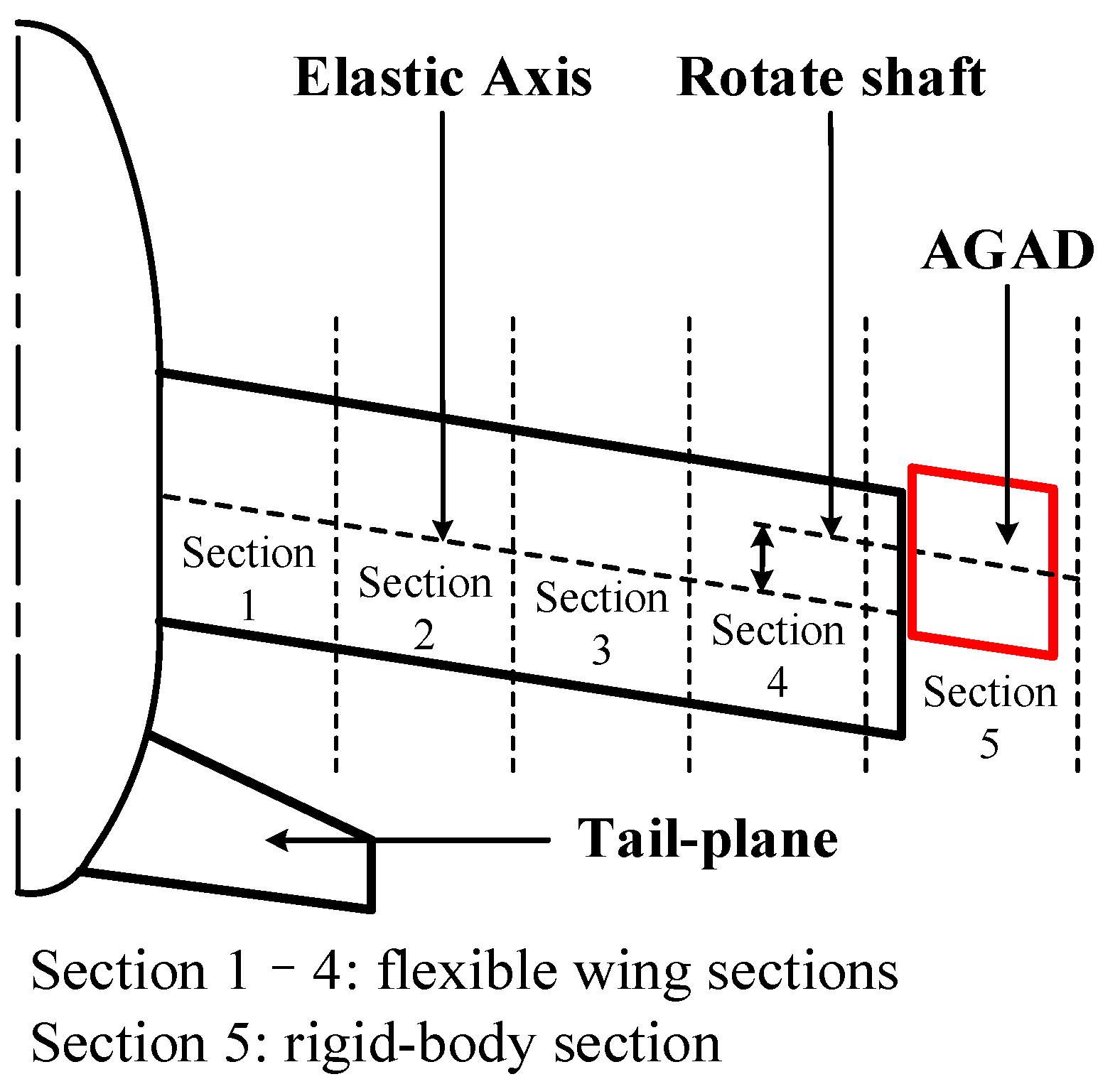
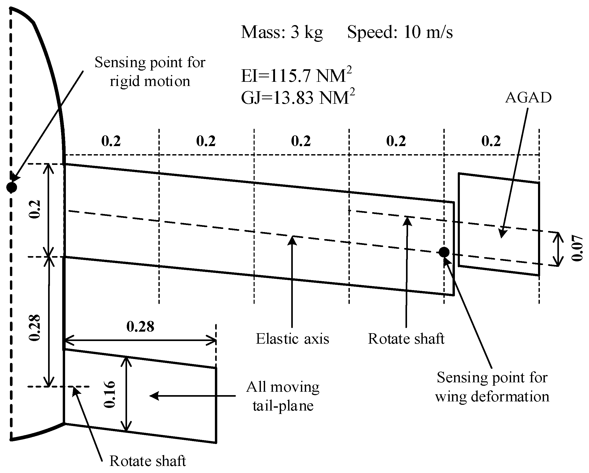
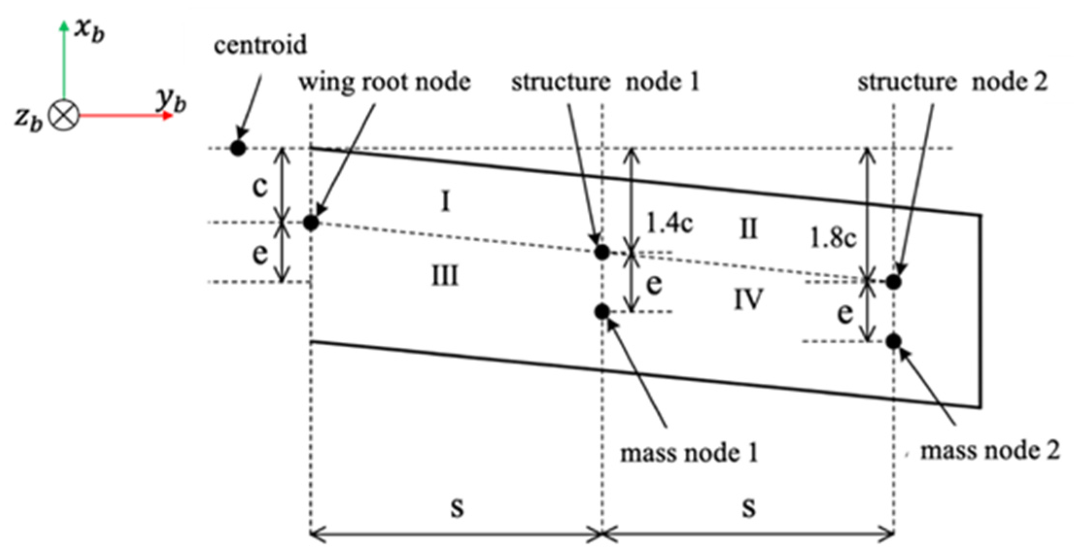
The AGAD, in the form of a rigid control panel, is part of the wing and an alternative control surface, as shown in
Figure 1. The AGAD is mounted at the wingtip through a shaft driven by an actuator to control the rotation angle. By setting the shaft axis in a proper chord-wise location on the AGAD and the tip of the inner wing, the AGAD will be able to alter the wing aerodynamic force and pitching moment to actively control the aircraft’s performance.
Figure 1 shows the finite element model of a flexible wing structure, which is a beam model arranged along the elastic axis of the wing. There is a structural node possessing three degrees of freedom on each section: vertical displacement, bending angle, and twist angle. Through this model, we can calculate the mass matrix and stiffness matrix of the wing, as detailed in [
37].
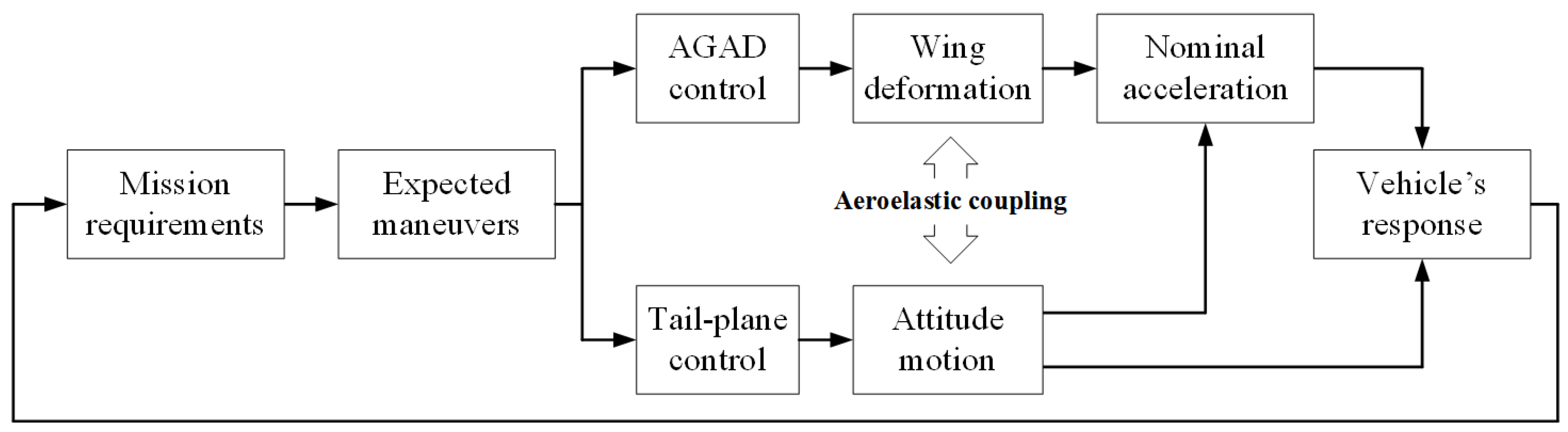
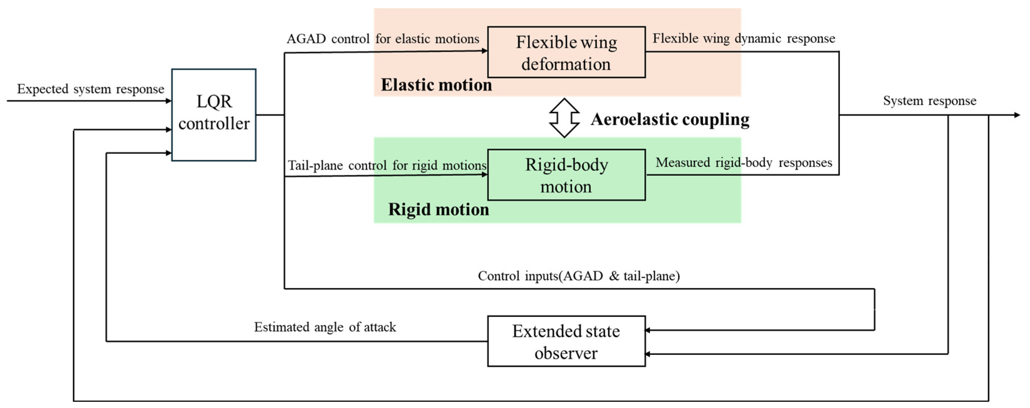
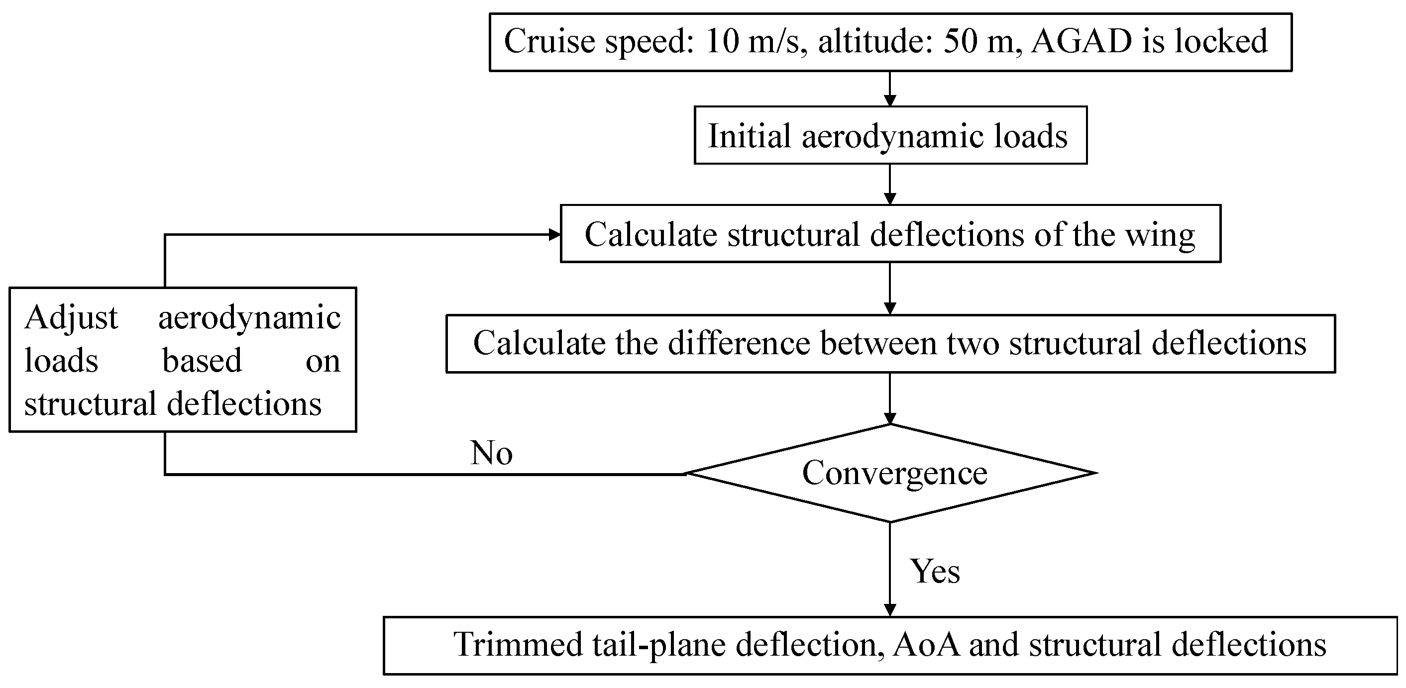
The aircraft flight attitude is mainly controlled by the tail-plane, which also influences normal acceleration. The control of the AGAD is thus coordinated with the wing deformation and tail-plane control simultaneously, as illustrated in
Figure 2.
Specifically, the control system for small flexible aircraft equipped with AGAD consists of two main components, as illustrated in
Figure 3. The first part is an LQR controller, which tracks the expected system response using the AGAD and the tail-plane. The flexible wing dynamic response and the measured rigid-body response are combined to form the overall system response. The second part is an ESO, designed to estimate the angle of attack (AoA). Its inputs include the system response and the control inputs from both the AGAD and tail-plane. In this paper, the AoA is defined relative to the CG of the aircraft.
There are three main objectives to achieve in the design of this control system. Firstly, a simplified low-order control model is created that takes the quasi-static aeroelastic effect of the flexible wing into account. Secondly, the LQR controller is designed to alleviate the gust load and meet the maneuver requirement by using the AGAD and tail-plane in an optimal combination. Finally, a method based on ESO is developed to estimate the equivalent AoA caused by gust load.
2.1. Integrated Aircraft Dynamic Model
By adopting the residualized model method [
38,
39,
40,
41], the flexible-wing aircraft state-space model of longitudinal dynamic motion, including the wing aeroelastic effect, can be given by
where
xR(
t) = [
α(
t),
q(
t),
θ(
t)]
T is the state vector of aircraft rigid-body motion;
α(
t) represents AoA; and
q(
t) and
θ(
t) represent the angular speed and angle in pitch motion, respectively.
xU(
t) = [
xE] is the state vector of the structural elastic deflection of the wing, which contains structural deformation displacement and structural deformation velocity.
xE and
only contain three mode shapes since the contribution of higher-order modes to elastic deformation is negligible due to their high frequencies (
Appendix A.1/
Table A1).
u(
t) = [
δe(
t),
δa(
t)]
T is the control input vector, in which
δe(
t) and
δa(
t) are the input rotation angles for the tail-plane and the AGAD, respectively.
ARR and
AEE represent the state matrices for the aircraft rigid-body motion and structural elastic deflection, respectively.
ARE and
AER are the state matrices of coupling between the rigid-body motion and elastic deflection.
BRR,
BRE,
BER, and
BEE are the input matrices for the aircraft motion control, including both rigid-body and structural elastic deflection effects.
If we expand the
xU term in Equation (1), then it can be rephrased as follows:
where [
ARE−1 0] = [
ARE−1 ARE−2] =
ARE, [0
AER−2] =
AER. Due to the lower flight speed and smaller deformation amplitude of the flexible wing structure, quasi-steady aerodynamic forces dominate. The vortex lattice method is used to calculate quasi-steady aerodynamic forces [
42]. When only considering quasi-steady aerodynamic forces, the submatrix,
ARE−2, related to structural deformation velocity,
, is 0.
Deformation of the membrane wing structure (
xE) can be divided into two parts: instantaneous equilibrium deformation of the membrane wing structure (
xEB) and residual deformation of the membrane wing structure (
). The modal frequencies of flexible wings are significantly higher than the short-period motion frequency of the aircraft, and our calculation results have once again verified this point; the specific calculation results are included in
Appendix A.1/
Table A1. Therefore, the fast time-varying state variable,
, can be ignored. Thus, we obtain a reduced-order model for controller design, which serves as the core model for dynamic analysis and control design in this paper:
where the system matrix,
A, and the input matrix,
B, are given by the following equation, and the specific derivation process has been added to
Appendix A.2 to avoid affecting the main logic of this paper:
Matrices
A and
B incorporate aeroelastic coupling through the residualization process, ensuring that the rigid–flexible interactions are adequately represented for control design purposes. The specific expression of terms in
A and
B is provided in
Appendix A.3.
2.2. LQR Controller Design
For the gust alleviation and maneuver control of a flexible-wing aircraft with multiple control surfaces, the LQR is selected as the core control algorithm. Compared to classical PID control, which is inadequate for systematically coordinating multiple actuators and balancing competing objectives, the LQR provides an optimal framework for multi-input coordination based on the established linearized model. It naturally balances these goals through a quadratic cost function. In contrast to sliding mode control, whose potential chattering might excite the flexible structure, the LQR delivers smoother control actions. Furthermore, compared to MPC, which demands high computational resources for online optimization and robust control methods, which are often complex and conservative, an LQR achieves satisfactory performance with a significantly lower computational burden and greater ease of engineering implementation. This makes it particularly suitable for resource-constrained small aircraft platforms.
The LQR controller is chosen for its optimality in minimizing a quadratic cost function for linear systems with multiple control inputs and states. Given that the reduced-order model in Equation (3) is linear and captures the coupled rigid-body and aeroelastic dynamics, LQR provides an effective framework for coordinating the tail-plane and AGAD controls by minimizing a quadratic cost function:
where
Q1 is a design variable that can take any symmetric semipositive definite matrix value, and
Q2 is a design variable that can take any symmetric positive definite matrix value.
The tracking error
e(
t) is defined as
where
z(
t) is the tracking signal, and
xR(
t) is the system response.
The optimal control input
u* is given by
in which
P can be obtained by solving the Riccati equation, and
g(
t) can be calculated from the differential equation:
The tracking signal, z(t), provides the specified target maneuver of the aircraft for the LQR controller based on the current flight condition and performance. The target maneuver is that the aircraft needs to achieve the specified flight performance, such as a specified climb at a certain altitude.
For heave motion, the target maneuver, such as a specified climb rate, can be determined by
where
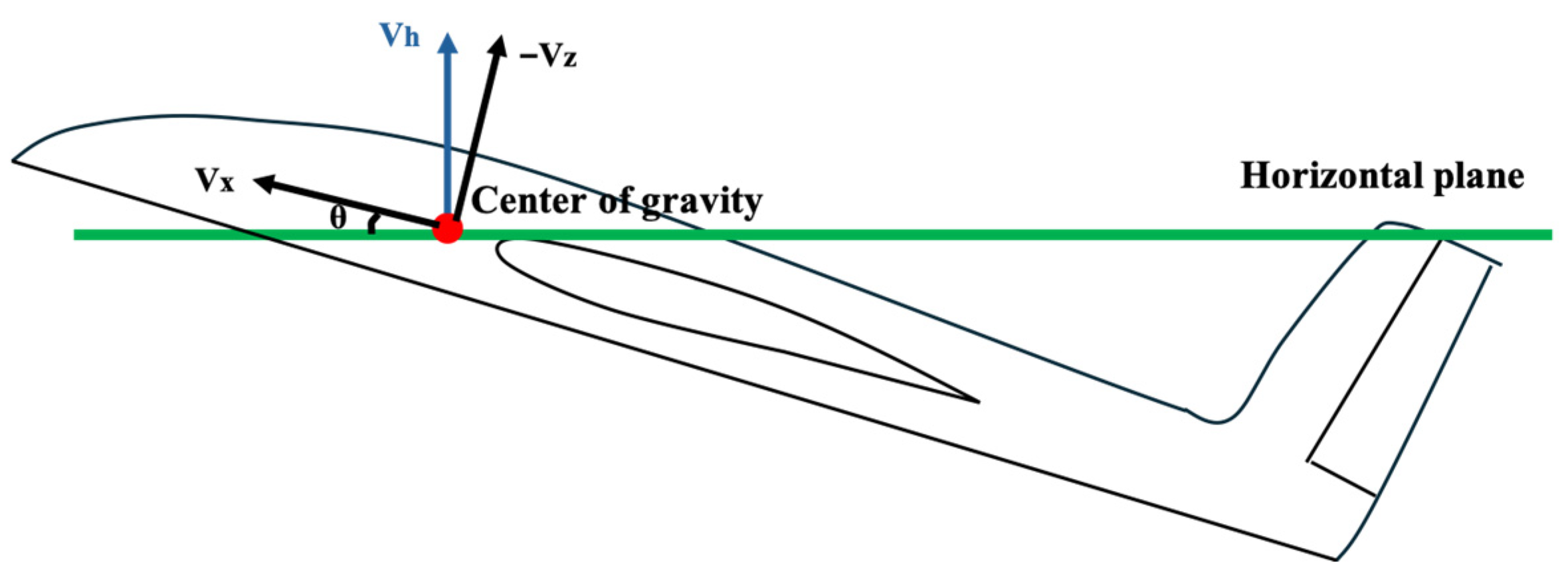
Vh is the vertical velocity of the aircraft defined in a ground global coordinate system with a positive axis in an upward direction;
Vx and −
Vz are the velocity components measured in the local coordinate system with the x-axis pointing toward the nose direction, the y-axis pointing toward the right-wing direction, and the z-axis pointing below the aircraft;
θ is the pitch angle, defined as nose-up positive.
Figure 4 clarifies the relationship between these variables.
Assuming
Vx is maintained as stable by an independent feedback control loop, the climb acceleration is given below:
where
is the dynamic pressure (
= 0.5
ρV2),
S is the wing area,
m is the total mass of the aircraft,
Cα is the aircraft lift curve slope, and
α(
t) is the equivalent AoA excluding the geometric AoA set in trimmed flight.
For a specified climb acceleration,
ah(
t), the relation between the tracking signal of AoA (
α*) and the tracking signal of pitch angular speed (
q*) is given by
In addition, the tracking signal of pitch angle (
θ*) is defined as
where
θ(
t) is the aircraft pitch angle at time
t, ∆
T is a differential amount of time, and
μ is an amplification factor.
θ*(
t) provides an approximate prediction of the pitch angle at time step
μ∆
T ahead, beyond the moment at time
t, to enable the LQR controller to suppress potentially excessive pitch angles in advance when tracking commands, thereby improving the dynamic response quality of the aircraft and preventing excessive control. It depends upon the tracking signal of pitch angular speed,
q*(
t). A cost function can be created as follows, and the optimal combination of tracking signals is determined by minimizing the cost function:
where
Wα,
Wq, and
Wθ are the weighting factors. Based on the optimal tracking signals, it is possible for the LQR control system to prevent an excessively large pitch angle by restricting the tracking signal of pitch angular speed,
q*(
t).
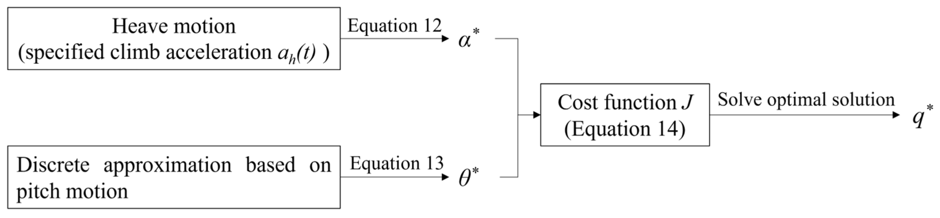
In summary, the proposed control architecture consists of two functionally distinct layers. The upper command generator layer, governed by Equations (12)–(14), translates flight tasks and operational constraints into a set of time-varying optimal tracking signals z(t). The lower LQR controller layer utilizes the cost function in Equation (5) to drive the aircraft state to optimally track the command from the upper layer.
Figure 5 depicts the whole process of obtaining the tracking signal,
z(
t).
Combined with Equations (12) and (13), the optimal tracking signals for the LQR controller are given by
where
K1 and
K2 can be expressed as follows:
It should be noted that K2 is an intermediate time-dependent parameter depending upon the aircraft flight speed, attitude, and specified climb acceleration and does not appear in the LQR controller.
According to Equation (16), for a specific climb acceleration, ah(t) > 0, and a predicted excessively large pitch angle, θ(t), for example, the K2 would be negative, and K1 > 0. In this case, though the specified maneuver is to climb, there would be a negative tracking signal for the pitch angular speed to be q*(t) < 0. As a result, the LQR controller will command the tail-plane to reduce the likely excessive pitch angle by setting q(t) < 0 and actuate the AGAD to achieve the required climb acceleration, ah(t) > 0.
2.3. Evaluation of Equivalent AoA Due to Gust by ESO
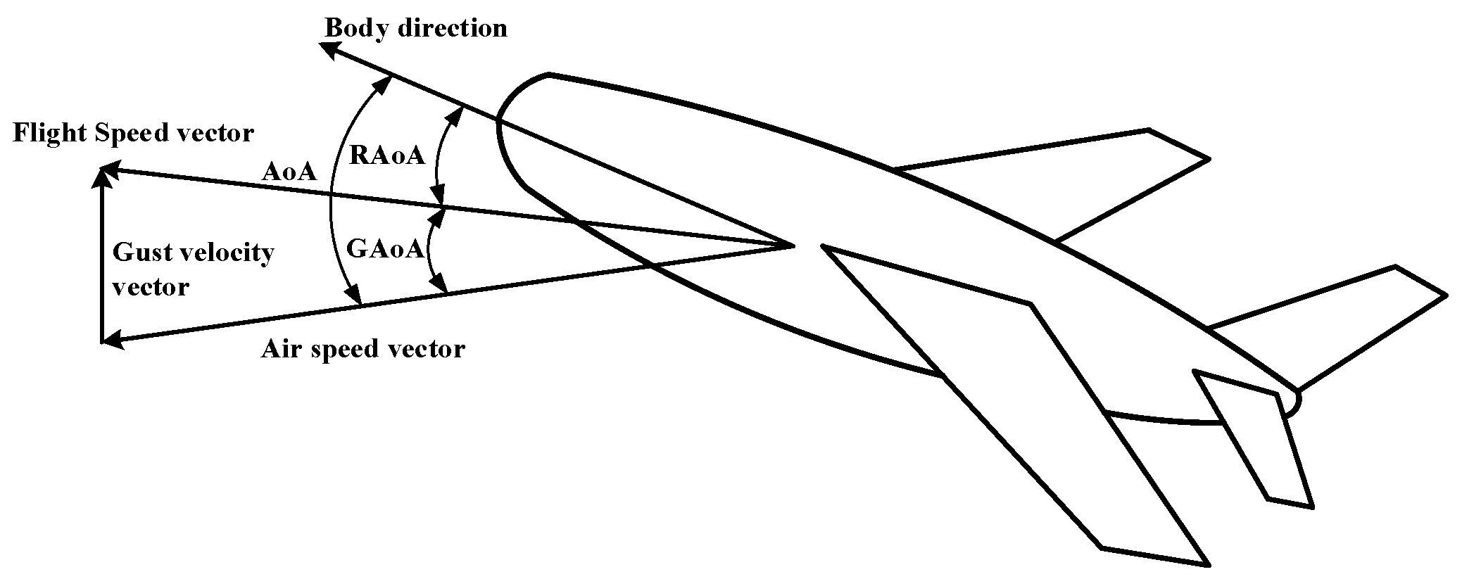
AoA is defined as the angle between the air speed vector and the x-axis of the aircraft coordinate system. Our miniaturized low-cost aircraft installs an inertial measurement unit (IMU), which can measure the pitch angle of the aircraft (
θ), and a GPS-assisted navigation system, which can measure the flight path angle (
γ). The vector difference between
θ and
γ can characterize the angle between the flight speed vector and the x-axis of the aircraft coordinate system, and we define this angle as the rigid-body motion angle of attack (RAoA,
αr). Flight speed vector is consistent with air speed vector under the still-air assumption, and AoA can be characterized by
αr. However, the vector sum of the air speed vector and vertical gusts is the direction of the aircraft flight speed vector under vertical gusts. That is to say, there is an additional angle induced by gusts between the air speed vector and the aircraft flight speed vector, and we define it as gust-induced angle of attack (GAoA,
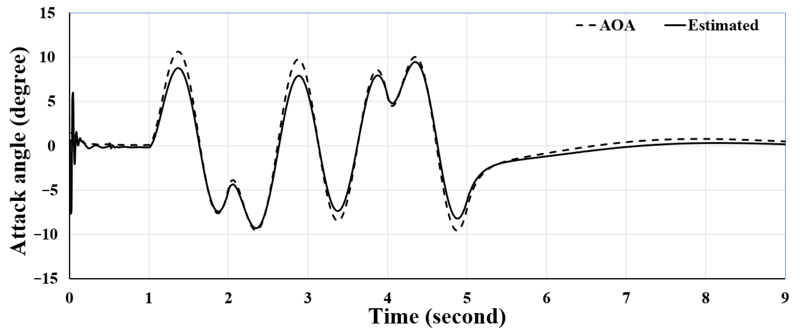
αg). Since this angle cannot be measured by onboard equipment, we have designed an ESO to observe it. Consequently, AoA under gusts should be expressed as
α =
αr +
αg. The relationship between these angles are depicted in
Figure 6.
In order to provide a clear physical derivation basis, we need to specifically expand the state variables and control variables in Equation (3). The more detailed expression of short-period longitudinal motion is given below:
where
Aii is the non-zero term of the system matrix,
Bii is the non-zero term of the input matrix, and the details of these terms refer to [
43]. Therefore, Equation (17) is essentially an equivalent expansion of Equation (3), which explicitly incorporates the GAoA (
αg) and its rate,
, as disturbance inputs, directly affecting the RAoA rate (
) and the pitch acceleration (
). Physically,
represents the time-varying component of the vertical gusts, and its inclusion ensures that the model captures not only the instantaneous gust impact but also its dynamic evolution.
For an undisturbed angular movement, according to Equation (17), the angular acceleration is dependent upon flight conditions and control input:
When the aircraft encounters gusts, only
αr can be measured by the flight controller through the integrated sensing and navigation system. Although
αg could not be measured, it can be indicated by the aircraft’s angular acceleration observed by
Accurately estimating αg is critical for effective gust alleviation, yet this state is not directly measurable. Among various estimation algorithms, the ESO is employed for its superior robustness and adaptability in the face of model uncertainties and unknown disturbances. Unlike the Kalman filter, which relies on precise statistical models of the disturbance, the ESO does not require a pre-defined gust model. It innovatively treats unknown external disturbances and model inaccuracies collectively as an extended state for real-time estimation and compensation. Compared to a Luenberger observer, which depends on an accurate linear system model, the ESO exhibits stronger robustness.
Specifically, a nonlinear continuous ESO is designed in this work, grounded in the active disturbance rejection control (ADRC) methodology [
44]. The actual flight dynamics involve complex, transient gusts and unmodeled rigid–flexible couplings, which challenge a purely linear observer. The nonlinear ESO provides a critical advantage: its fal(·) function ensures faster convergence and greater robustness against model mismatches during rapid transients compared to a linear counterpart. This design makes it particularly suitable for the high-performance disturbance estimation required in this work, as supported by its prior success in aerospace applications [
45,
46]. The ESO can be expressed as
in which
E is an evaluation error of the ESO,
Z1 and
Z2 are the observer outputs, and
β01 and
β02 are the observer gains. The parameters
β01 and
β02 are systematically designed based on the observer bandwidth concept. For a second-order ESO designed for a first-order system in Equation (20), the characteristic equation of its error dynamics is
. Placing both poles at −
ω0 to achieve a desired bandwidth,
ω0, yields the parameterization
β01 ≈ 2
ω0,
β02 ≈
ω02. The bandwidth must be substantially higher than the dominant disturbance frequency. Given the aircraft’s short-period mode frequency of 0.994 Hz, the target observer bandwidth
fBW =
ω0/(2π) is set to 10–15 Hz (
ω0 ≈ 60–90 rad/s). Initial gains derived from
ω0 = 90 rad/s (
β01 = 180,
β02 = 8100) are refined through simulation on the rigid–flexible coupling model to balance convergence speed with noise sensitivity and robustness to model uncertainties. This is achieved by evaluating the root mean square error of the AoA estimation to quantify convergence performance, while simultaneously injecting noise into the pitch rate measurement to assess the resultant fluctuations in the estimated
αg and thus gauge noise sensitivity. Furthermore, robustness is tested by varying key aerodynamic derivatives and monitoring the stability and accuracy of the estimation. Through parameter sweeps and a trade-off analysis of these criteria, the final values,
β01 = 100 and
β02 = 7000, are selected.
The nonlinear function, fal(·), in Equation (20) is defined as [
44]
where 0 <
α1 < 1,
δ > 0. The function operates in two regimes to enhance performance: for large errors (|
E| >
δ), the term
provides superlinear convergence, enabling rapid rejection of significant disturbances. For small errors (|
E| ≤
δ), it switches to a linear gain,
, which mitigates high-frequency chattering and improves noise immunity near equilibrium. The choice of parameters
α1 = 0.5 and
δ = 0.05 is the result of a simulation-based trade-off study, as mentioned before, seeking an effective balance between aggressive disturbance estimation and smooth observer output. For appropriate values of
β01,
β02,
α1, and
δ, the observer output,
Z1, approaches the angular velocity, and
Z2 approaches the angular acceleration.
The part of angular acceleration that is contributed by measured flight conditions and control input has already been included in the second equation of Equation (20). The rest of the equation, which is (
Z2 −
β01E), represents the portion of the angular speed that is contributed by gusts. According to Equation (19),
αg can be estimated by
4. Discussion
In recent years, small flexible-wing aircraft have undergone rapid development for urban applications due to their flexibility and maneuverability. However, their operation at low Reynolds numbers makes them susceptible to gust disturbances, posing significant challenges to flight stability.
To address this problem, gust alleviation strategies have been explored. Passive techniques utilize anisotropic composite materials, while active methods employ control surfaces. Although it is simpler to implement, passive alleviation is generally less effective than its active counterpart. In this study, we propose a hybrid approach by designing an AGAD attached to the wingtip to work in concert with the conventional tail-plane for enhanced flight attitude control.
Our research mainly focuses on vertical gust disturbances—the primary threat to small, low-inertia aircraft due to rapid changes in the effective AoA. Consequently, an integrated longitudinal aircraft dynamics model was presented using the residualized model method, incorporating aeroelastic effects. Given the multi-variable control nature of this system, an LQR scheme was adopted. An ESO was utilized to estimate the complete AoA under gust conditions, which comprises the RAoA and gust-induced GAoA.
The effectiveness of the AGAD was validated through simulations of a small flexible-wing aircraft. Two configurations were compared: a baseline case with tail-plane control only and an AGAD case with unified AGAD and tail-plane control. Evaluations included gust response and maneuver performance without gusts.
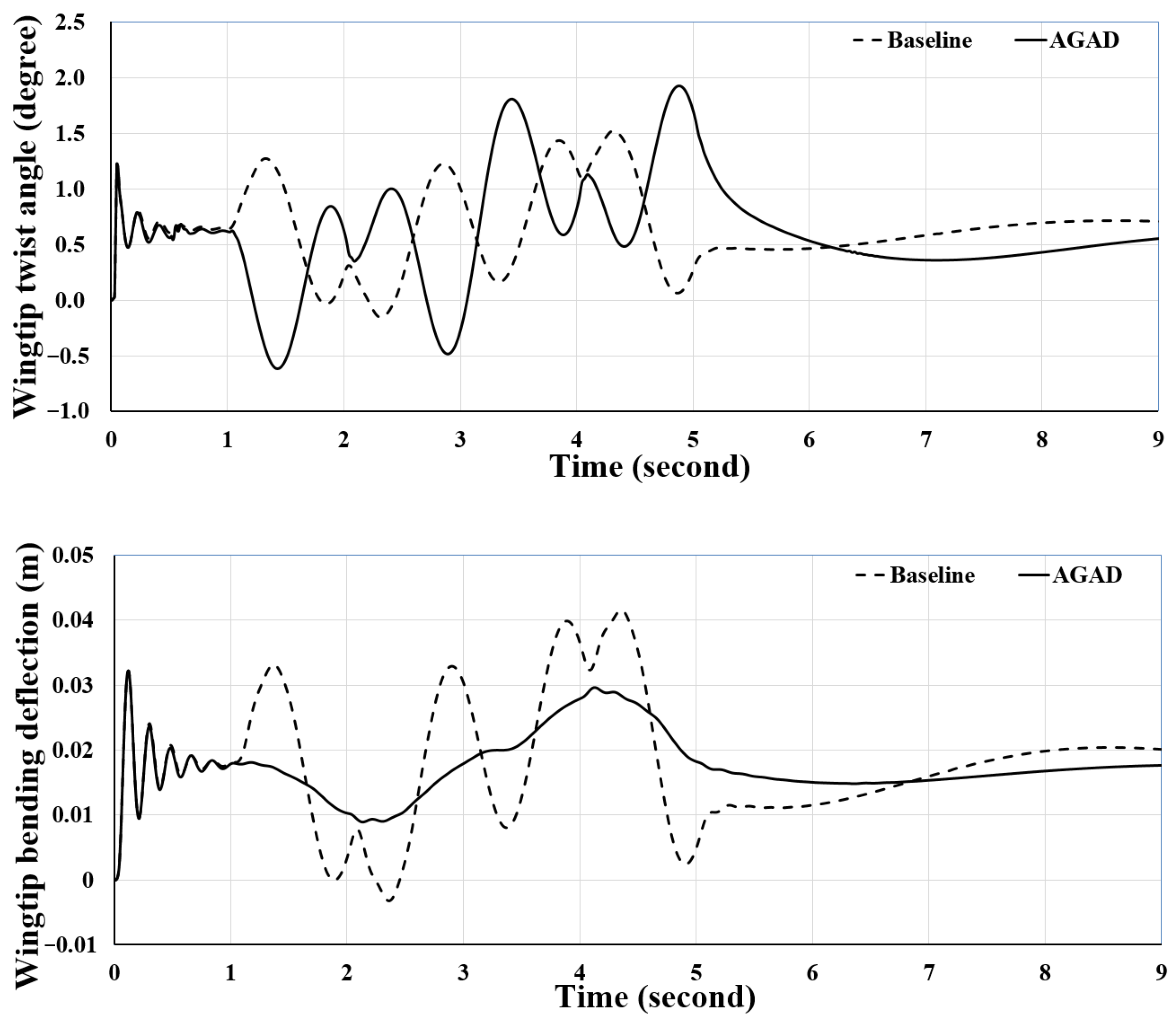
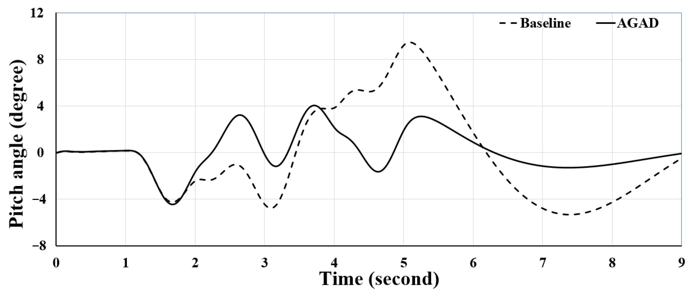
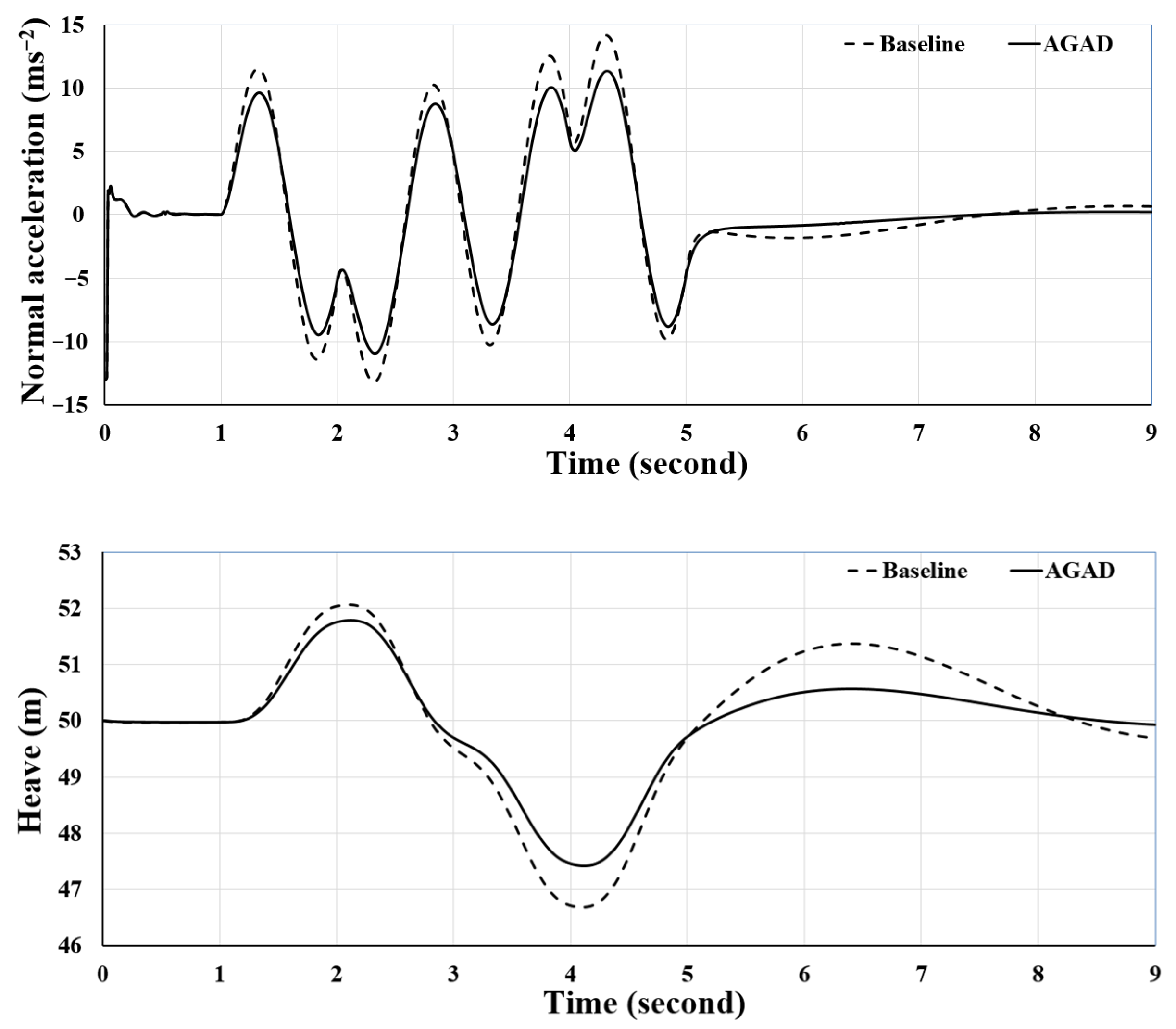
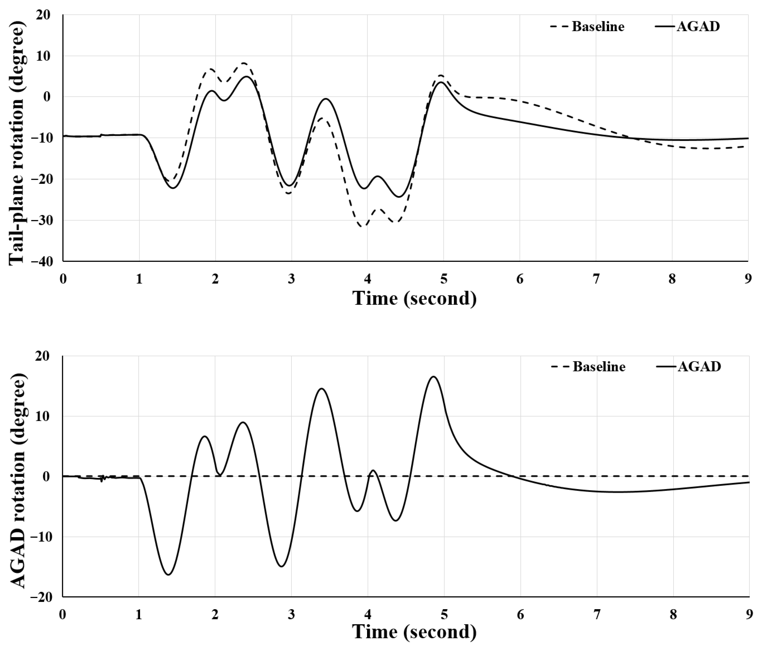
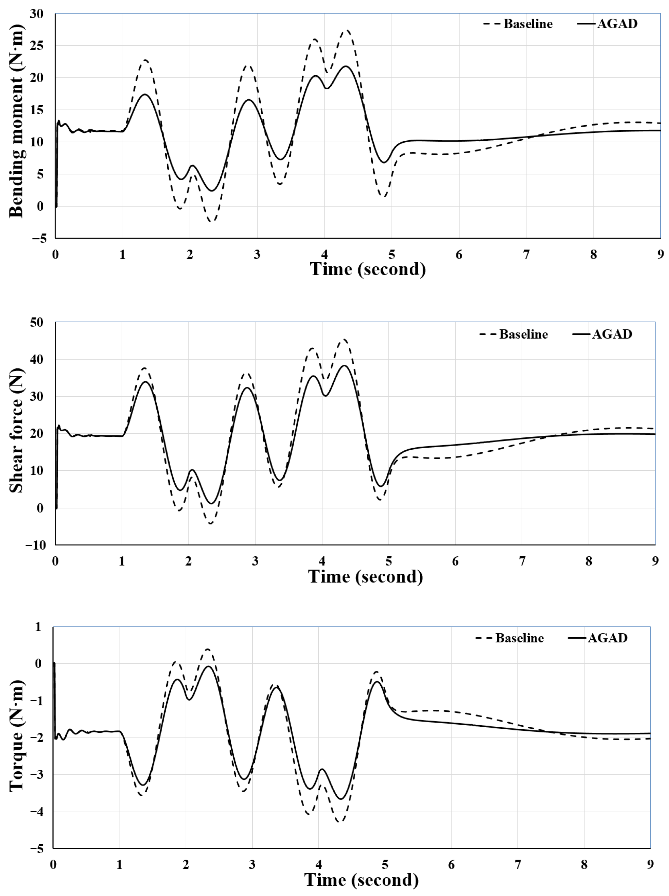
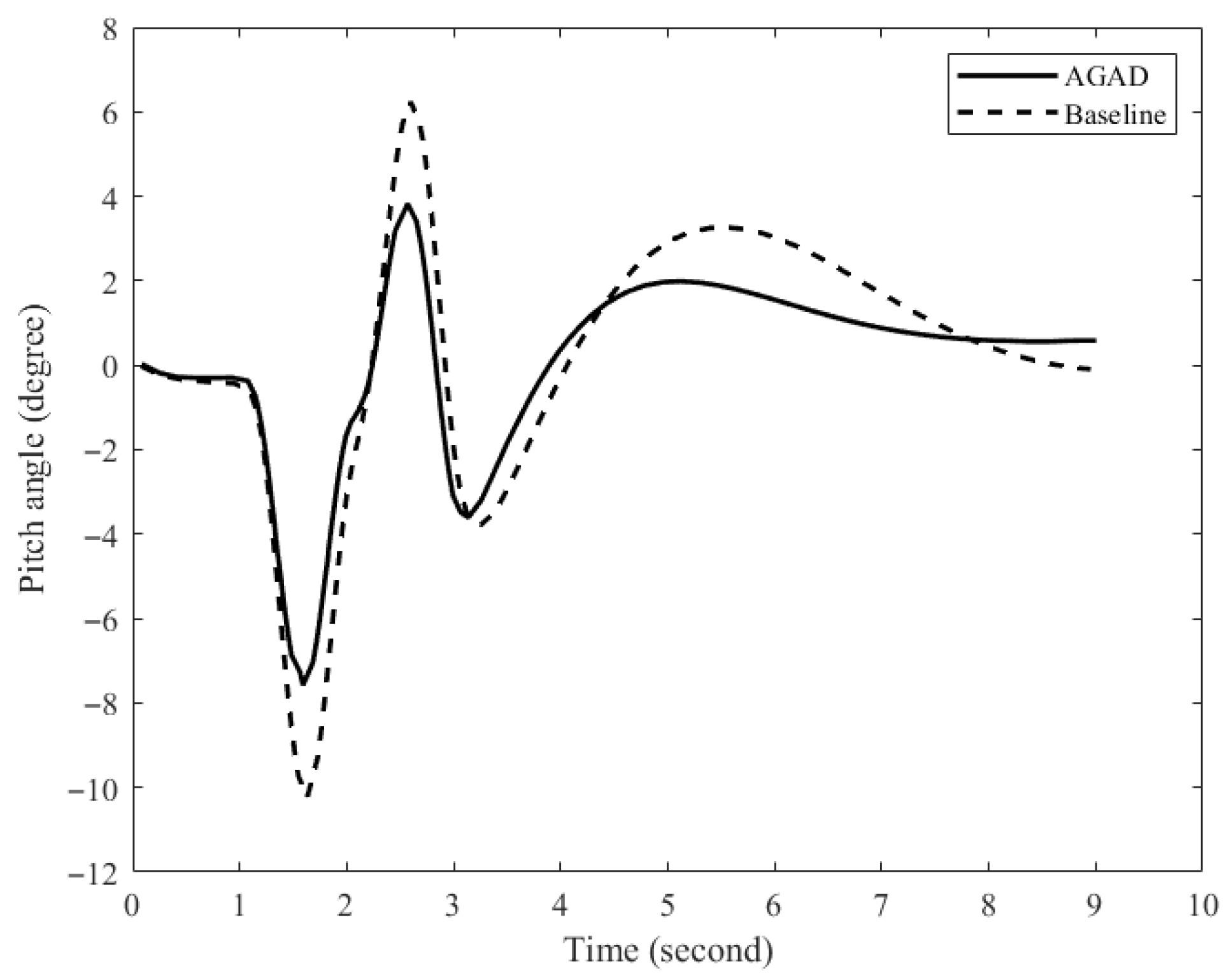
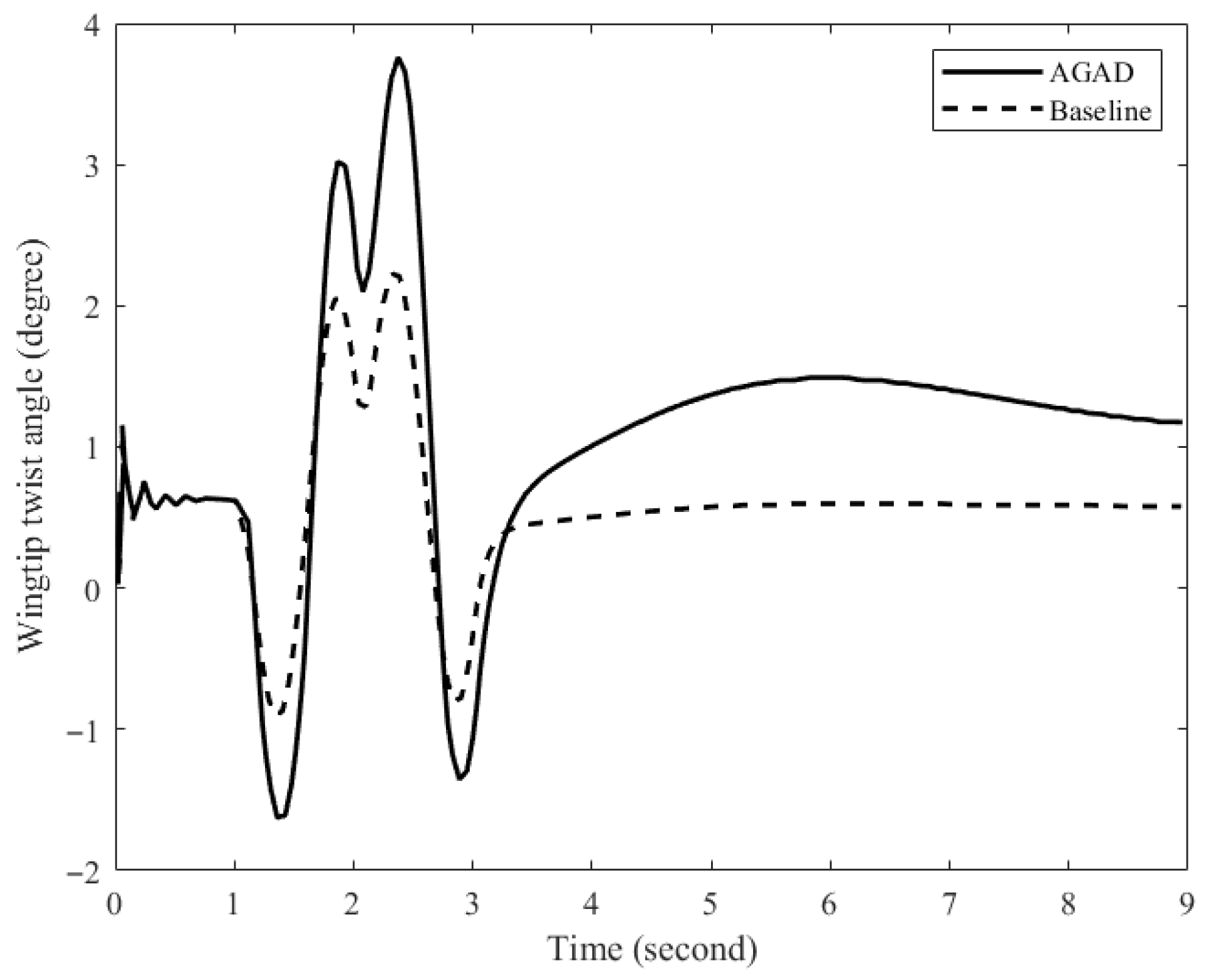
The gust response simulations demonstrated that the AGAD configuration significantly improved performance with lower control effort. Specifically, compared to the baseline, the AGAD case reduced pitch angle peak by 57.46%, normal acceleration peak by 20.28%, and heave displacement peak by 21.99%, indicating substantially improved flight stability. Notably, while the wingtip twist angle peak increased by 28% (reflecting a more effective gust alleviation ability), the structural loads were markedly reduced: wingtip bending deflection peak decreased by 29.27%, wingroot bending moment peak by 20.87%, wingroot shear force peak by 15.22%, and wingroot torque peak by 14.69%. This suggests that the AGAD not only suppresses gust effects but also enhances structural safety by redistributing and alleviating air loads. Furthermore, the required tail-plane rotation angle peak was reduced by 23.06%, implying savings in control effort.
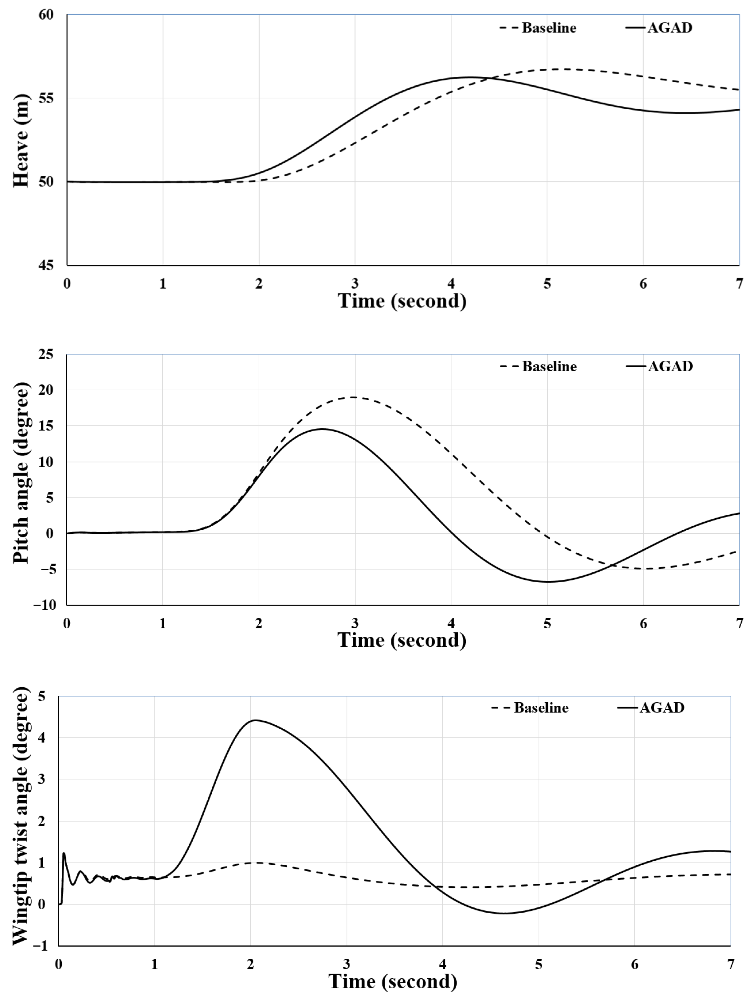
In maneuver simulations, the aircraft equipped with AGAD exhibited greater agility. It reached a specified altitude 1 s faster than the baseline, with a 23.74% reduction in pitch angle peak. This enhanced maneuverability is attributed to the ability of AGAD to generate rapid and large-amplitude wingtip twist responses, providing additional pitch control power.
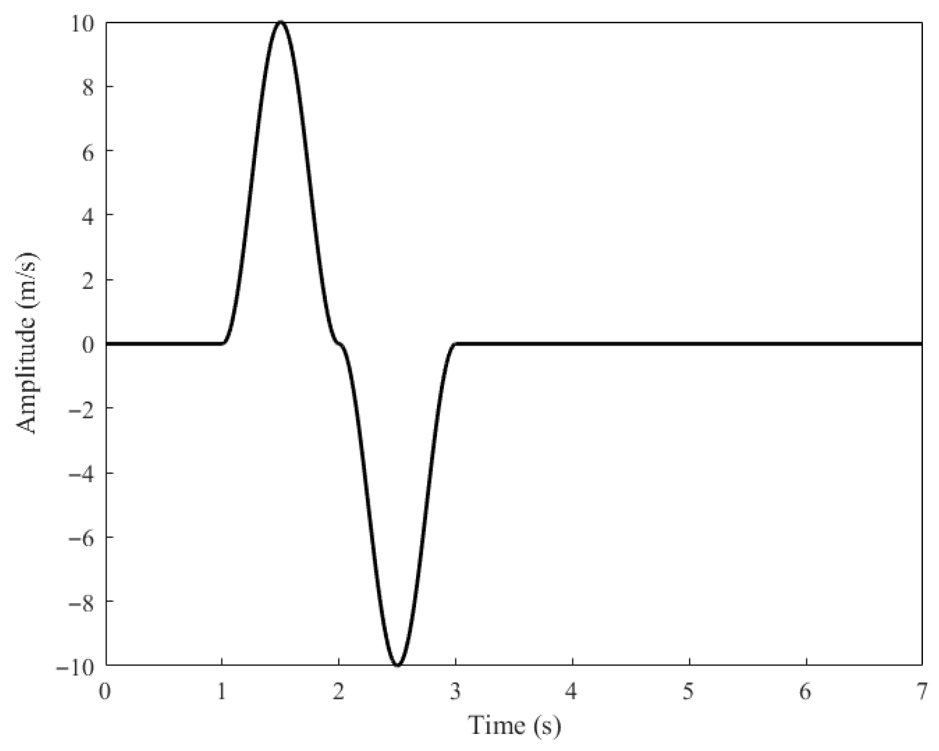
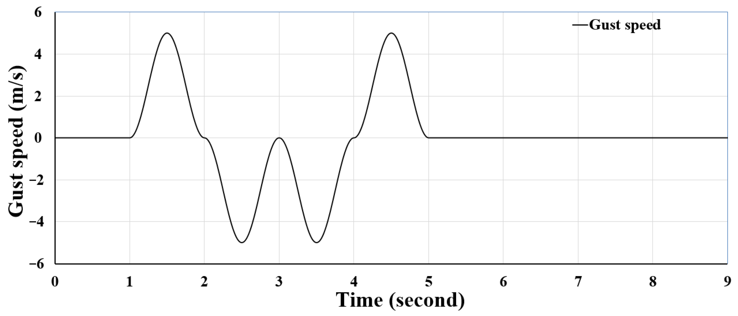
While the simulations demonstrate significant performance improvements under the designed cruise condition and a standard (1 − cos) gust, the robustness of the proposed AGAD control strategy to operational uncertainties is a critical aspect for practical deployment. The robustness of the proposed control strategy can be evaluated by examining the fundamental assumptions of its underlying model. Firstly, the reduced-order model’s validity is contingent upon the aircraft operating sufficiently below the flutter speed. Within this flight envelope, the model intrinsically captures the effects of varying speed and altitude through the aerodynamic derivatives. Secondly, the ESO does not rely on a pre-defined gust model. Its fal(·) function is designed for rapid estimation of aggregated disturbances, granting the controller inherent adaptability to diverse gust profiles, including non-periodic ones like clear air turbulence. Finally, the core premise of the model reduction is the frequency separation between rigid-body and elastic dynamics. The control framework remains applicable as long as this separation is preserved under variations in wing stiffness, defining a clear and practical robustness threshold. To evaluate its robustness, AGAD control is tested in
Appendix A.5 under varying gust amplitudes and shapes. The results remained consistent with those in the main text, demonstrating a reduction in pitch angle and an increase in wingtip twist angle compared to the baseline, thereby illustrating the robustness of the control strategy.
It is also important to address the system-level implications of integrating AGAD. Our study focuses on longitudinal gust alleviation, where the two AGADs mounted on the wingtips are operated symmetrically to counteract vertical gusts. In this symmetric mode, the AGAD has a minimal impact on lateral control authority. Furthermore, the auxiliary AGAD adds weight and drag. The AGAD mechanism adds approximately 0.1 kg to the aircraft, which is marginal relative to the total mass of 3 kg. Similarly, the AGAD panel area of 0.04 m2 is small compared to the total wing area of 0.4 m2, suggesting a manageable impact on overall drag. While these penalties are non-negligible, they are decisively outweighed by the fundamental improvements in flight safety and gust alleviation capability—a critical enhancement for reliable operation in complex, low-altitude missions such as environmental monitoring and disaster response.
Beyond the weight and drag considerations, the practical feasibility of the proposed AGAD control system is a key consideration. The control commands generated by the LQR controller, with a maximum absolute deflection of approximately 24° for the tail-plane and 16° for the AGAD, fall well within the typical mechanical range of standard small UAV servos. Furthermore, the control system only needs to respond to low-frequency dynamics dominated by the aircraft’s short-period mode (0.994 Hz). The resulting bandwidth requirement is modest and well within the performance envelope of common servo actuators. Regarding the concern of sensor noise, it is important to note that the employed nonlinear ESO itself possesses inherent noise-suppression capabilities, which are factored into its fal(·) design, allowing the ESO to differentiate between noisy signals and true disturbances. Therefore, although the current validation is simulation-based, the proposed control system’s demands on actuation and sensing align well with the capabilities of commercially available components, supporting its feasibility for future physical implementation.
To further illustrate the contribution of this work, the proposed AGAD is contrasted with active multi-flap systems from the literature, such as the work by Berg et al. [
27], as well as with the actively controlled FFWT system studied by Narimani et al. [
32]. The multi-flap system, employing six independently actuated trailing-edge flaps, represents a high-performance yet high-complexity approach to load alleviation, requiring intricate actuation coordination, high-fidelity aeroelastic modeling, and multi-sensor fusion. Similarly, the FFWT system utilizes a linear model predictive control strategy combined with unsteady aerodynamic modeling based on Theodorsen’s theory, which, while effective in gust load alleviation and limit-cycle oscillation suppression, demands significant computational resources and accurate disturbance prediction. In contrast, as summarized in
Table 6, the AGAD scheme adopts an intentionally simplified design suitable for resource-constrained platforms. It utilizes a single wingtip control surface on one side of the wing instead of a complex multi-flap or morphing wingtip system, prioritizing flight stability and primary structural load control for small flexible aircraft. The comparison demonstrates that the AGAD achieves gust alleviation performance comparable to both the multi-flap and FFWT systems in key metrics, despite a drastic reduction in system complexity. Consequently, this work establishes that the AGAD presents a practical alternative for small UAVs, offering a favorable trade-off between performance and complexity for cost- and weight-sensitive applications.
In future work, we will explore the integration of recent advancements in morphing wing technology based on the AGAD concept. This may involve incorporating additional control surfaces and diverse control modes, including differential AGAD actuation for roll control to further improve the stability, maneuverability, and agility of flexible-wing aircraft, ultimately enabling safer and more reliable operations in complex urban environments and expanding their potential applications.
5. Conclusions
This study proposes an integrated strategy based on an AGAD and an LQR-ESO control framework to enhance the flight stability and maneuverability of small flexible-wing aircraft in gust environments. By establishing a reduced-order model that considers aeroelastic effects and designing an ESO to estimate the GAoA in real time, optimal coordinated control between the AGAD and the all-movable tail-plane is achieved.
The simulation results demonstrate that, compared to the baseline case using tail-plane control alone, the proposed AGAD strategy achieves significant improvements in multiple aspects. In the study of flight stability under gusts, at the rigid-body motion level, the peak pitch angle, normal acceleration, and heave displacement are reduced by 57.46%, 20.28%, and 21.99%, respectively; at the structural load level, the peak wing root bending moment, shear force, and torque are reduced by 20.87%, 15.22%, and 14.69%, respectively; at the control efficiency level, the peak tail-plane deflection angle is reduced by 23.06% and the RMS index by 14.41%. Furthermore, by inducing a 28% increase in wingtip twist angle, the AGAD reduces the peak wingtip bending deflection by 29.27%, achieving a more favorable aerodynamic load distribution, which further verifies its mechanism of enhancing gust alleviation capability through aeroelastic coupling. In the study of maneuverability, utilizing the AGAD reduces the time to complete a specified climbing task by 1 s and lowers the peak pitch angle by 23.74%.
This study not only confirms the effectiveness of the AGAD in gust control for small flexible aircraft but also provides a practical solution that balances performance and complexity for resource-constrained platforms. Future work will explore the integration of AGAD with roll control and its further application in complex urban environments.