


Abstract
As a high-precision and high-stability engineering platform for aerospace missions, the dual-super spacecraft is subject to numerous environmental constraints and disturbances in increasingly complex space environments, posing significant challenges to its attitude maneuvering process. Unlike traditional spacecraft, the dual-super spacecraft consists of two cabins: a payload cabin and a platform cabin, with a magnetic levitation mechanism installed between them to prevent vibration transmission. This paper establishes a multi-coupled attitude model for the payload cabin, the platform cabin, and the magnetic levitation mechanism between them. Additionally, a collision avoidance control strategy is designed for the magnetic levitation mechanism to ensure the operational safety of the entire system. To address the external environmental constraints, a closed-loop dual-loop control framework is proposed for the payload cabin. The outer-loop performs stability control on the payload cabin, while the inner-loop employs explicit reference governor (ERG) to handle pointing constraints. The platform cabin follows the attitude control of the payload cabin, forming a master–slave coordinated control scheme. Simulation results demonstrate that the proposed multi-coupled control system framework performs effectively, ensuring both the satisfaction of pointing constraints and the operational safety of the dual-super spacecraft system.
Keywords:
closed-loop inner-outer dual-loop; constrained control; explicit reference governor; non-disturbance payload MSC:
93-02
1. Introduction
High-value spacecraft executing space missions impose stringent requirements on their payloads, namely ultra-high precision and ultra-high stability. Traditional monolithic spacecraft designs face several challenges: their complex structures lead to dynamical models that cannot accurately capture the coupling relationships in the dynamics of separated dual modules; the elastic structural components, such as solar panels [1], as well as severe vibrations transmitted through the rigid–flexible connections between cabins [2,3], collectively impose significant constraints on further improvements in payload stability and pointing accuracy; and factors such as large payload inertia and multi-source disturbances from space environmental perturbations [4,5] among others, collectively pose significant negative impacts on the efficient execution of exploration missions.
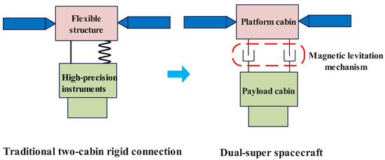
Nelson Pedreiro proposed the concept of the Disturbance-Free Payload (DFP) satellite in 2003 [6], which incorporates non-contact actuators between the satellite cabins to isolate the payload from other mechanisms, thereby enhancing payload precision and addressing the aforementioned issues [7,8]. Building on the DFP satellite concept, Chinese scholars introduced the notion of a dual-super spacecraft—characterized by ultra-high precision and ultra-high stability. Its structure consists of three parts: a payload cabin housing high-precision equipment, a platform cabin containing moving parts and flexible components, and a non-contact magnetic levitation mechanism connecting two cabins. Zhang Wei et al. from the Shanghai Institute of Satellite Engineering designed a collaborative control strategy for the dual-super spacecraft and demonstrated its effectiveness [9]. However, this work did not address the impact of multi-coupling relationships among various components of the spacecraft on operational safety. During large-angle attitude maneuvers, significant errors may occur, potentially leading to collisions between the cabins. Liao et al. proposed a self-recovery controller based on chaos control methods to address single-rod faults in magnetic levitation spacecraft, thereby improving the operational safety of the spacecraft [10].
Additionally, spacecraft are usually subject to directional interference from the environment during exploration. For instance, in Earth observation, thick cloud cover and electromagnetic interference can affect the imaging and identification capabilities of electronic reconnaissance satellites and optical imaging satellites [11,12,13,14]. As a result, the line-of-sight axis of the spacecraft’s optical payload must avoid these environmental constraints and undergo real-time attitude adjustments. While performing detection tasks, the spacecraft must also transmit acquired data back to ground stations and maintain communication. Therefore, the dual-super spacecraft must operate under specific pointing constraints.
Existing constrained attitude control methods include optimal control [15], model predictive control (MPC) [16,17], and adaptive attitude control [18]. Optimal control transforms constraints into optimization objectives, balancing performance index minimization with state vector fluctuation reduction [19]. Although it delivers high control performance, it demands substantial computational resources and high-precision models, making it unsuitable for spacecraft with limited computational capabilities. MPC solves constrained optimization problems online, featuring strong disturbance rejection and multi-constraint handling capabilities [20]. The MPC method in [21] employs a dual-loop structure that integrates Laguerre functions with multi-parametric quadratic programming (mp-QP) to reduce online computational and data storage demands while expanding the feasible region of the MPC optimization problem. However, this approach still requires the online computation of several weighting coefficients, resulting in a computational load that remains higher than that of offline computed control methods. Additionally, the control performance is subject to dependency on the accuracy of the system model. Adaptive attitude control [22] is less model-dependent and more computationally efficient. Nevertheless, this method tightly couples stability, constraint avoidance, and parameter adaptation into a single complex control law, requiring simultaneous consideration of multiple factors during the design process.
This paper designs a closed-loop inner–outer dual-loop control framework, which incorporates reference variable into the error control process. This reference variable is also driven to converge asymptotically toward the desired objective, while the controlled object follows it to achieve the desired objective. Accordingly, the control architecture is decomposed into inner and outer loops: the outer-loop is responsible for stability control to improve accuracy, and the inner-loop employs an explicit reference governor (ERG) to enforce constraints. This method involves designing the derivative of the introduced reference variable, utilizing an artificially constructed potential function to shape a navigation field along with a safety margin function for constrained regulation, which offers a more transparent and structurally simpler framework. Ref. [23] presents a generic and systematic framework for the ERG control law. Rather than being limited to a specific design method, it distills the two core components of ERG—the dynamic safety margin and the navigation field—and provides multiple systematic design approaches and sufficiency conditions for both. Ref. [24] further introduces a dynamic safety boundary for the safety margin function of ERG, enabling real-time assessment of how close the system state is to the constraint boundary. The ERG control law involves the offline design of the derivative for the reference variable. Additionally, the artificial potential functions are pre-designed, which themselves require minimal computational effort. For dynamic attitude maneuvers, ERG does not necessitate global trajectory planning but rather solves the problem within a relatively local scope. These advantages collectively result in a significantly lower computational load for ERG control compared to other methods. However, these ERG-based studies do not adequately address the requirement for high control accuracy in spacecraft missions—such as precision in attitude quaternion, attitude angle, and angular velocity—nor do they deal with highly coupled dynamic structures like that of the dual-super-spacecraft system.
The current dual-super platform technology system is still in the engineering verification stage, and its application is largely confined to small satellite platforms such as the “Xihe” satellite. Moreover, it has not yet undergone attitude maneuver capability tests under complex working conditions. The main contributions of this paper to the two challenges faced by the attitude maneuvering of the dual-super spacecraft mentioned above are as follows:
- A quaternion-based error attitude dynamics model is established for the payload cabin. The platform cabin tracks the payload cabin, and an error dynamics model is constructed relative to the attitude of the payload cabin. A non-contact magnetic levitation mechanism introduces attitude states of the payload cabin and the relative attitude error between the two cabins, thereby establishing a dynamics model for collision avoidance control. As a result, the overall dynamics model of the spacecraft is highly coupled, which further enhances operational safety. Meanwhile, the multi-coupled dual-super spacecraft model established in this paper enables a comprehensive analysis of control effectiveness from the perspectives of quaternion, attitude angle, and angular velocity, thereby meeting the ultra-high precision and ultra-high stability requirements essential for space missions. This represents a key emphasis of this paper.
- A closed-loop inner-outer dual-loop control framework is developed for the payload cabin. In the inner-loop, constraint handling is achieved via ERG control law utilizing a navigation field and artificial potential function, while a safety margin function is introduced to quantify the system’s capability to avoid constraint violations. Moreover, this offline design method offers reduced computational load and complexity compared to other constrained control strategies, such as MPC. In the outer loop, a control law is designed to ensure system stability and fulfill the dual-super requirements of ultra-high precision and ultra-high stability for space missions. This aspect receives greater emphasis in this work compared to other ERG control strategies and is supported by rigorous stability proofs. Compared to adaptive control, which tightly integrates stability, constraint handling, and parameter adaptation into a single, complex framework that must address multiple objectives simultaneously, this dual-loop design offers a simpler and well-controlled structure. In addition, a quasi-sliding mode controller (QSMC) has been designed for the platform cabin to achieve master–slave cooperative control. A collision avoidance strategy has also been developed based on the coupled dynamics of the non-contact magnetic levitation mechanism, ensuring that the relative displacement between the two cabins remains within a safe range. This ultimately guarantees the safety of the entire dual-super spacecraft system during attitude maneuvers. Together, these components form an integrated control framework centered on the ERG approach, enabling systematic boundary control for the coupled attitude dynamics of the dual-super spacecraft system.
2. Control Model of Dual-Super Spacecraft
2.1. Spacecraft Attitude Dynamics
The spacecraft attitude quaternion is defined as , where is the scalar part and is the vector part. Let denote the skew-symmetric matrix of ,
is the rotation matrix, and is the identity matrix.
The dynamic equation for quaternions is
where quantifies the spacecraft’s angular velocity within the common coordinate system, , .
For a given desired quaternion , the error quaternion between and is quantified by
Defining the rotation angles about the X, Y, and Z-axes as roll (), pitch (), and yaw (), the attitude rotation matrix of the satellite is
2.2. Spacecraft Payload Cabin and Platform Cabin Dynamic Models
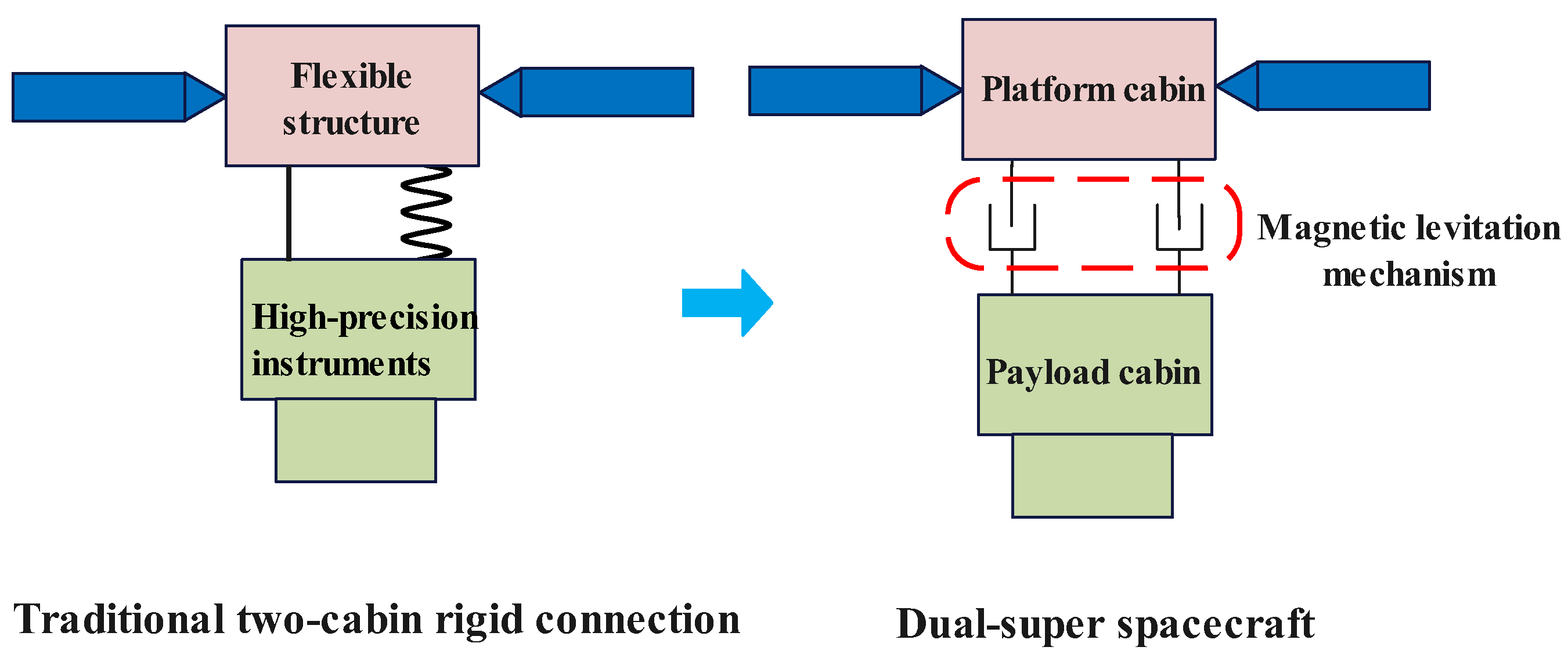
A schematic diagram of the dual ultra-precision spacecraft is shown in Figure 1.
Figure 1.
Schematic diagram of dual-super spacecraft.
The payload cabin is equipped with high-precision photosensitive devices and can be treated as a rigid-body spacecraft. Its dynamic equation takes the form
where denotes the inertia matrix of the payload cabin, represents the payload cabin’s angular velocity in the payload cabin’s reference frame, and is the control torque acting on the payload cabin, and is the disturbance torque on the payload cabin.
Let be the scalar part of the error quaternion between and . Define and it is worth noting that to ensure the existence of matrix P, matrix T must be invertible, which requires to be non-zero. Substitute (2) into Equation (5), and according to reference [25] the quaternion-based dynamic equation of the payload cabin can be derived as
where is the vector part of the error quaternion , , , .
The platform cabin, which is structurally complex, can be regarded as a flexible structure spacecraft. Its dynamic equation takes the form:
where denotes the inertia matrix of the platform cabin, and represents the platform cabin’s angular velocity in the platform cabin’s reference frame. The coupling coefficient matrix between solar panel vibrations and platform cabin rotation is defined as . represents the modal coordinates. The control torque acting on the platform cabin is , while denotes the disturbance torque. The modal frequency and damping ratio matrices of the solar panels are and .
2.3. Dynamic Model of Non-Contact Magnetic Levitation Mechanism
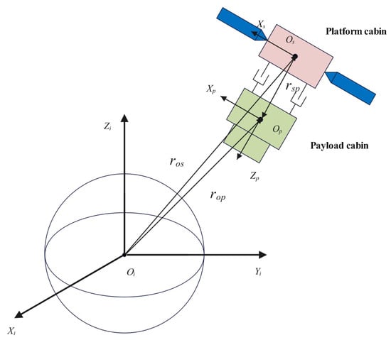
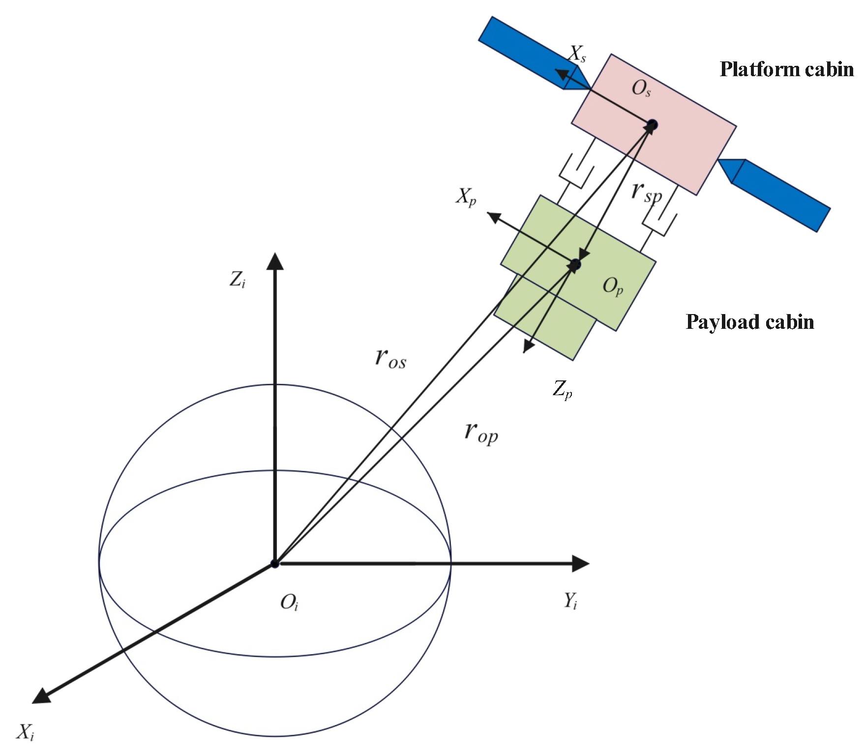
To mitigate collision risks, a collision avoidance model for magnetic levitation mechanism must address the relative position between coils and permanent magnets. In order to unify the control of variables in different compartments within the same frame coordinate system, the establishment of a coordinate system is essential. The platform cabin body-fixed frame is located at its CoM , and the payload cabin frame at . The inertial coordinate system is centered at geocentric position . The establishment of the coordinate system is schematically illustrated in Figure 2.
Figure 2.
Relative position vector between the centers of mass (CoM) of two cabins.
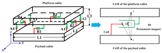
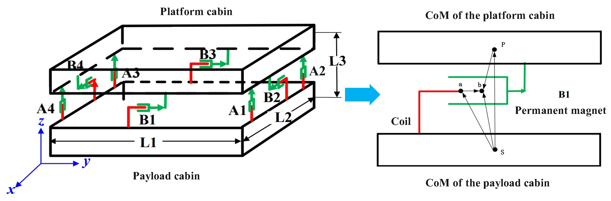
A total of eight symmetrically arranged non-contact magnetic levitation actuators are mounted between the payload and platform cabins (left portion of Figure 3), providing attitude control of the payload cabin and collision avoidance capability. In the schematic of mechanism B1 (right side of Figure 3), points P and S correspond to the CoM of the payload and platform cabins, whereas a indicates the endpoint of the coil assembly and b refers to the center of the permanent magnet.
Figure 3.
Relative Positioning of coils and permanent magnets in magnetic levitation systems [26].
The represents the relative position vector between coil and permanent magnet:
Here, the superscript on a variable specifies the coordinate system to which it belongs. represents the vector from the payload cabin CoM to the permanent magnet center b, and represents the vector from the platform cabin CoM to the coil endpoint a. As the magnet and coil are rigidly attached to their respective cabins, and remain constant in the payload cabin frame. represents the attitude rotation matrix of the payload cabin relative to the platform cabin, and denotes the three-axis attitude error Euler angles of the payload cabin relative to the platform cabin. According to the Taylor expansion, sin x = x − + …, and cos x = 1 − + … ; the error between sin x and x reaches 1% when x is smaller than 0.01 rad (approximately 0.57°), while the error for cos x remains below 0.005%. For the attitude maneuver of the dual-super spacecraft, the payload cabin and the platform cabin, due to the highly effective follow-up control (see Section 3.3 for the platform cabin control law), maintain a relative attitude error of less than 0.57° during large-angle attitude maneuvers, as specifically illustrated in the subsequent simulation results. Given that the relative attitude angles are relatively small, the approximations sinx and cos 1 hold true. The following approximations hold:
As indicated in Figure 3, magnetic levitation mechanisms B2 and B4 are responsible for actuating translational motion of the payload cabin along the -axis, while B1 and B3 provide control authority along the -axis. Mechanisms A1 through A4 collectively govern motion along the -axis. Hence, the relative displacement between the coils and permanent magnets in each translational axis of the magnetic levitation mechanism is given by
where i can take the values 2 or 4, j can take the values 1 or 3, k can take the values 1, 2, 3, or 4, is the component of on the x, y and z axes, and are the components of on the x, y and z axes.
Making and taking the second order derivative with respect to R yields
From (10) and (11), it can be seen that the change in R not only affects the relative attitude change in the two compartments, but more importantly, the core change is in the relative center of mass of the two compartments. As shown in Figure 2, the relative position vector between the cabins’ CoM, expressed in the inertial frame, is denoted as .
Here, vector represents the position from origin to the CoM of the payload cabin, and vector represents the position from origin to the CoM of the platform cabin. The magnitudes of these two vectors are approximately equal.
Based on the two-body motion equation, (12) can be reformulated as
Here, the control accelerations and represent payload and platform cabin motions, respectively, where and are equal and opposite control forces for the relative position between the cabins’ centers of mass.
The relative position vector derivative between the cabins’ CoM satisfies
Substituting (13) into (14) yields the representation of the relative position vector between the CoM of two cabins in the payload cabin body frame:
During missions, the spacecraft operates at altitudes ranging from hundreds to tens of thousands of kilometers from the Earth. The difference between the magnitudes of the vectors and is approximately 0.65 m. Given that these vectors are on the order of hundreds to thousands of kilometers, this discrepancy is negligible. Thus, and can be considered identical and, the difference in acceleration due to Earth’s gravitational field between the CoM of two cabins can be neglected. Simplifying (15) gives the relative positional dynamics between the CoM of the two cabins:
Among them .
2.4. Spacecraft Attitude Maneuver Pointing Constraints
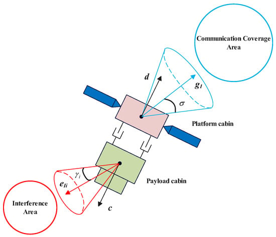
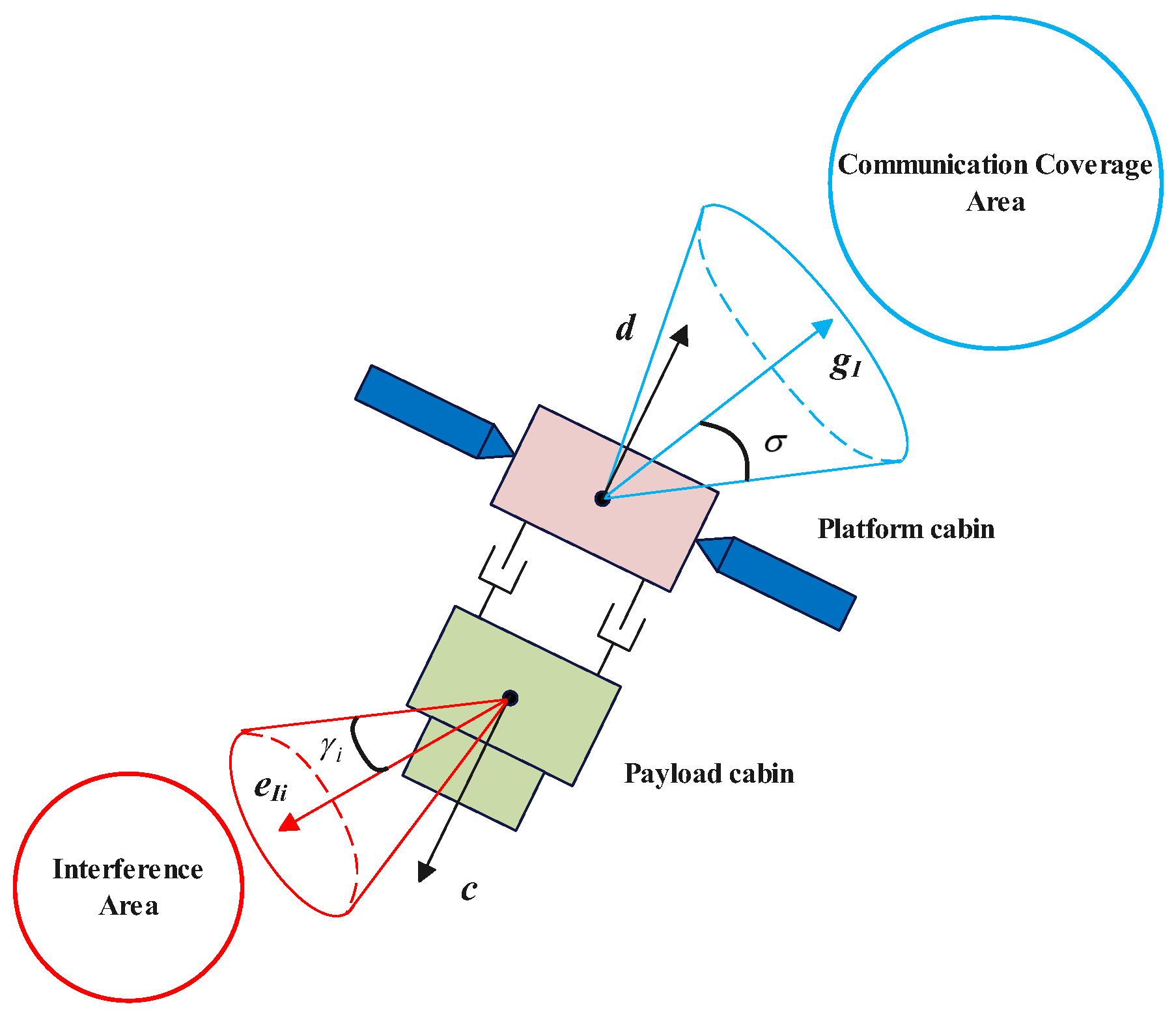
Throughout mission operations, the spacecraft is required to comply with the pointing constraints illustrated in Figure 4. Here, represents the high-precision instrument’s line of sight (LoS) fixed in the payload cabin, unit vector denotes the central axis of the forbidden LoS cone corresponding to the of the i-th interference zone in the inertial coordinate, is the semi-aperture angle of this LoS cone, and the must remain outside this cone. This constraint is mathematically expressed as
represents the communication axis fixed in the platform cabin, denotes the central axis of the communication cone corresponding to the communication coverage area for in the inertial coordinate frame, is the semi-aperture angle of this communication cone, and must remain within this cone. This constraint is mathematically expressed as
where is the error quaternion between and .
Figure 4.
Spacecraft pointing constraint diagram.
3. Spacecraft Attitude Maneuver Control Law Design
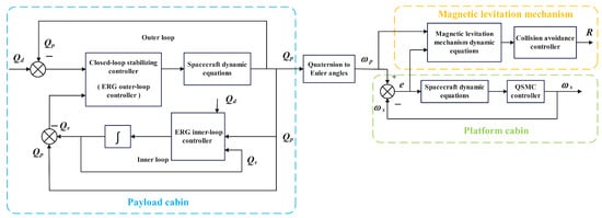
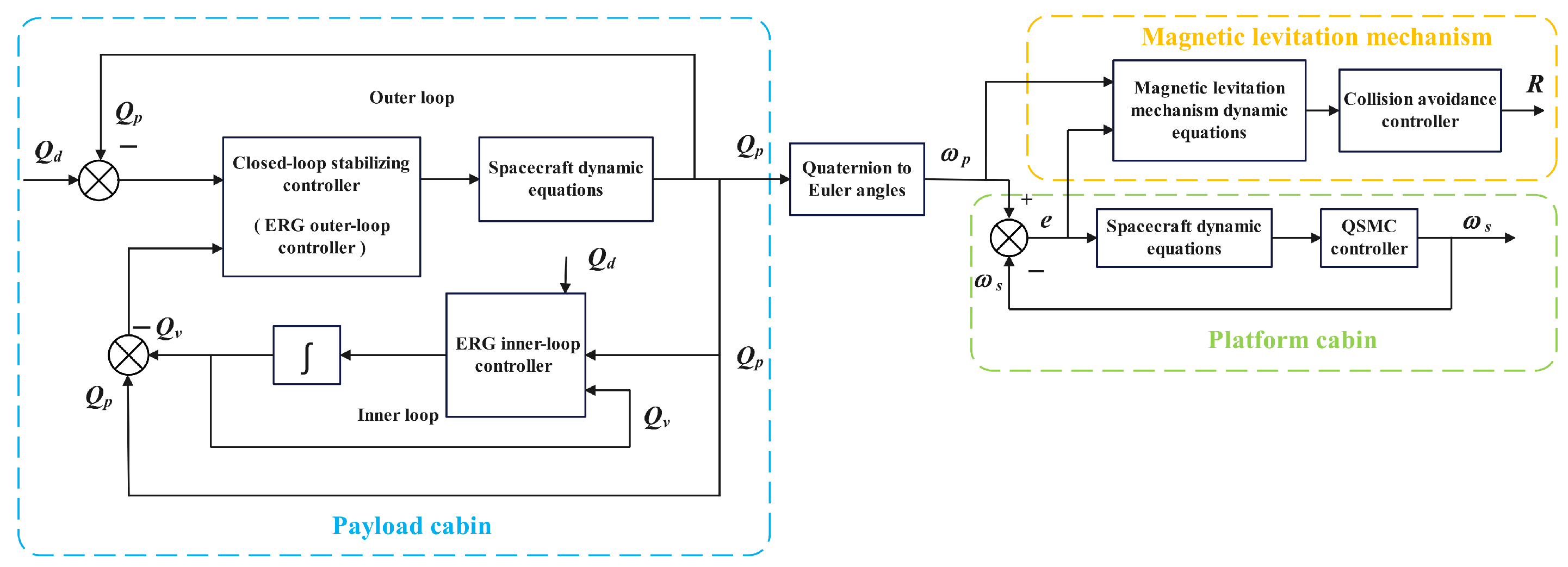
This chapter develops a closed-loop inner–outer dual-loop control framework for the payload cabin to achieve constrained attitude maneuvers. It introduces a reference variable into the error control process that drives the controlled variable to converge toward the desired target . In the inner-loop, by designing the derivative of , is constrained to satisfy system constraints while gradually converging toward . For the outer-loop, is forced to track through PD control, ensuring system stability. This dual-loop structure ultimately achieves the goal of driving to converge to , while a quasi-sliding mode control (QSMC) law is synthesized for the platform cabin to achieve coarse tracking of the payload cabin, fulfilling the master–slave collaborative control objectives. Concurrently, during spacecraft attitude maneuvers, a sliding mode control (SMC) law is designed for the non-contact magnetic levitation mechanism between the payload and platform cabins to ensure collision avoidance and operational safety. The complete control structure is presented in Figure 5.
Figure 5.
Dual-super spacecraft control system architecture diagram.
3.1. Outer-Loop Stabilization Control
This section designs the controller for the payload cabin, i.e., the outer-loop stabilization controller.
where is the vector component of the error quaternion between and , and and are positive real numbers.
Theorem 1.
Proof.
Consider the following Lyapunov candidate:
According to [25], it can be inferred that, for any vector the following relationship holds:
Therefore, we can obtain
After the final simplification, the result is
Applying the LaSalle’s invariance theorem allows us to find that , . □
3.2. Inner-Loop ERG Control Law
For the reference variable , design its derivative as
where the represents the dynamic safety margin, which quantifies the system’s capability to avoid constraint violations and denotes the navigation field, designed to drive toward convergence with .
Design the dynamic safety margin as [23]
Here, is a positive real number. V is the Lyapunov function of the payload cabin controller defined in the preceding text, represents the upper limit of this Lyapunov function, and when multiple constraints exist, this upper limit corresponds to the minimum value across all constraints:
Theorem 2.
Proof.
Let set and . The error quaternion are defined as follows: the scalar part is expressed as , while the vector part takes the form . Similarly, let set and . The corresponding expression for is as follows: the scalar part is expressed as , while the vector part takes the form .
Based on the normalization property of quaternions, the squared norm of the vector part satisfies
Substituting the scalar part, we obtain
(34) can also be expressed as
Since the quaternion closely tracks , the angular deviation is small and . It can be approximated as
Similarly, is small and .
The navigation field consists of an attractive navigation field , a repulsive navigation field , and a disturbance term . The guides the reference variable toward convergence with the desired target , while the ensures compliance with pointing constraints during maneuvering. It should be noted that critical equilibrium points may emerge during attitude maneuvers where the attractive and repulsive navigation fields balance each other, potentially causing the spacecraft to stagnate at a specific attitude instead of converging toward . To mitigate this risk, a disturbance term is introduced to disrupt this equilibrium state and enable the system to escape from critical points. The overall navigation field is thus formulated as follows:
The is formulated as [24]
where is the vector component of the error quaternion between and . is a small positive real number designed to prevent high frequency oscillations in when approaches zero.
The repulsive field is constructed using a quadratic parabolic potential function, which becomes active at point and attains its critical value at point . It is essential to preserve a safety buffer between and the angular boundary ( or ) defined by the constraints. The expression for is defined as follows:
where ∇ represents the gradient operation with respect to the angular coordinate.
The disturbance term in the navigation field is designed using the null space operations of a matrix. It is activated only when vectors and are in opposing directions and ensures compliance with the constraint conditions:
where .
The null-space vector is introduced as a critical enhancement to the navigation field to ensure global asymptotic convergence in spacecraft attitude control. When only attractive and repulsive potential terms are used, the resulting conservative vector field may cause the system to stagnate at saddle points—critical points that are not the global minimum. Defined as a unit vector in the null space of the governing matrix, the null-space vector is orthogonal to all vectors in that matrix and introduces a transverse perturbation without interfering with motion driven by the primary terms. This perturbation acts as a “pushing force” near saddle points, exploiting their inherent unstable directions to disrupt local equilibria and enable escape, thereby guaranteeing convergence to the target attitude.
3.3. Design of Control Law for the Platform Cabin
To achieve master–slave coordination control for the platform cabin to follow the payload cabin, a QSMC law is employed to regulate the attitude error between the two cabins.
Theorem 3.
For the platform cabin attitude error system defined by (7), in the absence of external disturbances, the designed QSMC law is
Here, ε, and are positive definite diagonal matrices. This control law guarantees asymptotic stability of the system at the equilibrium point (, ) = (0, 0).
Proof.
Consider the following Lyapunov candidate:
Taking its time derivative gives
Stability analysis confirms asymptotic convergence when = 0, . □
3.4. Collision Avoidance Control for Non-Contact Magnetic Levitation Mechanism
The sliding surface for the sliding mode control law of collision avoidance, based on eight relative position sensors and the relative position variable , is set as
Here, and are positive definite diagonal matrices, is a number greater than 0 and less than 1 and represents the sign function.
The collision avoidance control force is designed as
Select a Lyapunov function as follows:
Taking its time derivative gives
Stability analysis confirms asymptotic convergence when =0, .
It is important to note that for the sensors of the magnetic levitation mechanism, noise and time delay will inevitably affect the control performance of the actuator. To meet the collision avoidance requirements of the dual-super spacecraft, the displacement measurement accuracy is set at 30 m. Based on this accuracy, white noise should be incorporated into the simulation. Additionally, the sensor delay in the simulation is configured as 5 ms.
4. Simulation and Results
4.1. Spacecraft Attitude Maneuver Simulation Parameters
The structural parameters of the dual ultra-precision spacecraft are as follows: kg and kg denote the payload and platform cabin masses, respectively; m, m, and m represent the magnetic levitation mechanism dimensions (Figure 3). To avoid collisions between the magnetic levitation mechanisms of the two cabins, a safe distance between coils and permanent magnets must be designed. The allowable range of relative motion is between −5 mm and 5 mm.
Throughout mission operations, both the payload and platform cabins are required to satisfy the attitude pointing and stabilization accuracy specifications listed in Table 1, as dictated by the precision demands of the payload instruments. Attitude pointing accuracy refers to the angular deviation of a system after reaching a stable state, while attitude stability accuracy corresponds to the angular velocity error.
Table 1.
Spacecraft simulation technical specifications.
During missions, the payload and platform cabins must meet the attitude pointing and stabilization accuracy requirements in Table 1, driven by payload instrument precision needs. Attitude pointing accuracy is the angle error during stabilization, and attitude stabilization accuracy is the angular velocity error.
To evaluate the attitude maneuver capability of the dual-super spacecraft and verify compliance of the closed-loop inner–outer dual-loop control framework with constraints during the maneuver, as well as confirm the performance of the collision avoidance control law for the non-contact magnetic levitation actuator, simulations are conducted in MATLAB R2022b. The spacecraft’s starting attitude is = [0.7096, 0, 0, 0.7046]⊤, initial reference attitude = [0.7096, 0, 0, 0.7046]⊤, desired attitude = [1, 0, 0, 0]⊤, and boresight parameters = [0, 1, 0]⊤, = [1, 0, 0]⊤. Based on the mathematical relationship between the high-precision instrument’s LoS axis and the payload cabin attitude, the forbidden LoS cones are transformed into inertial-frame-fixed prohibited attitude cones (with axis and identical semi-vertex angle) to characterize interference constraints on attitude maneuvers. The prohibited attitude areas of the payload cabin in simulation are as follows: = ⊤ with a half-cone angle = 20°, = [0.5805, 0.7991, 0.1564]⊤ with = 25°, = [0.4755, −0.3455, 0.809]⊤ with = 30° and the communication boresight = [0.7991, 0.5805, 0.1564]⊤ with a half-cone angle = 60°.
The control parameters for the outer-loop of the payload cabin are designed as , . The control parameters for the inner-loop ERG controller are designed as ; the boundary margin of the repulsive potential function is set as ; , . For the payload cabin, a disturbance is introduced. The parameters for the QSMC of the platform cabin are designed as , , and . For the platform cabin, a disturbance is introduced. The parameters for the collision-avoidance SMC control of the magnetic levitation mechanism are set to , , and . The simulation outcomes of this paper are evaluated against the results of adaptive control method in [22], where the parameters are set as
The selection of the outer-loop control coefficients for the payload cabin is analogous to that of a PD controller. These coefficients are designed to enable the system to gradually stabilize and converge while maintaining satisfactory steady-state control accuracy. The inner-loop parameters are designed to ensure that the potential function—which handles constraint-related issues—remains within a reasonable range of influence. This guarantees that the potential function does not exert excessive force at distant attitude points, while enabling it to act rapidly as the system approaches the constraint boundaries to prevent violations, without overcompensating. As for the QSMC applied to the platform cabin, the parameter should not be set too large, as this could aggravate chattering in the system. Higher values of and can accelerate the convergence rate of the control law, but excessively high values may adversely affect system stability. In the SMC function designed for collision avoidance control, the parameters and significantly influence the system’s convergence rate. Excessively high values can exacerbate chattering or even lead to system instability, while values that are too low may compromise response speed and degrade control performance. The parameter is typically set around 0.5, as this value effectively strikes a balance between response speed and chattering suppression.
4.2. Payload Cabin Control Outcome Analysis
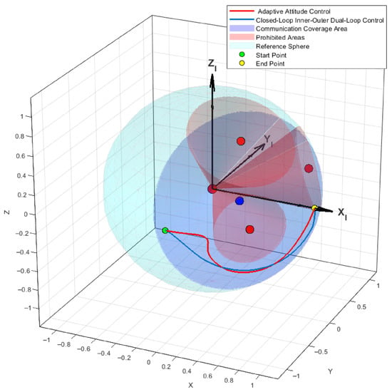
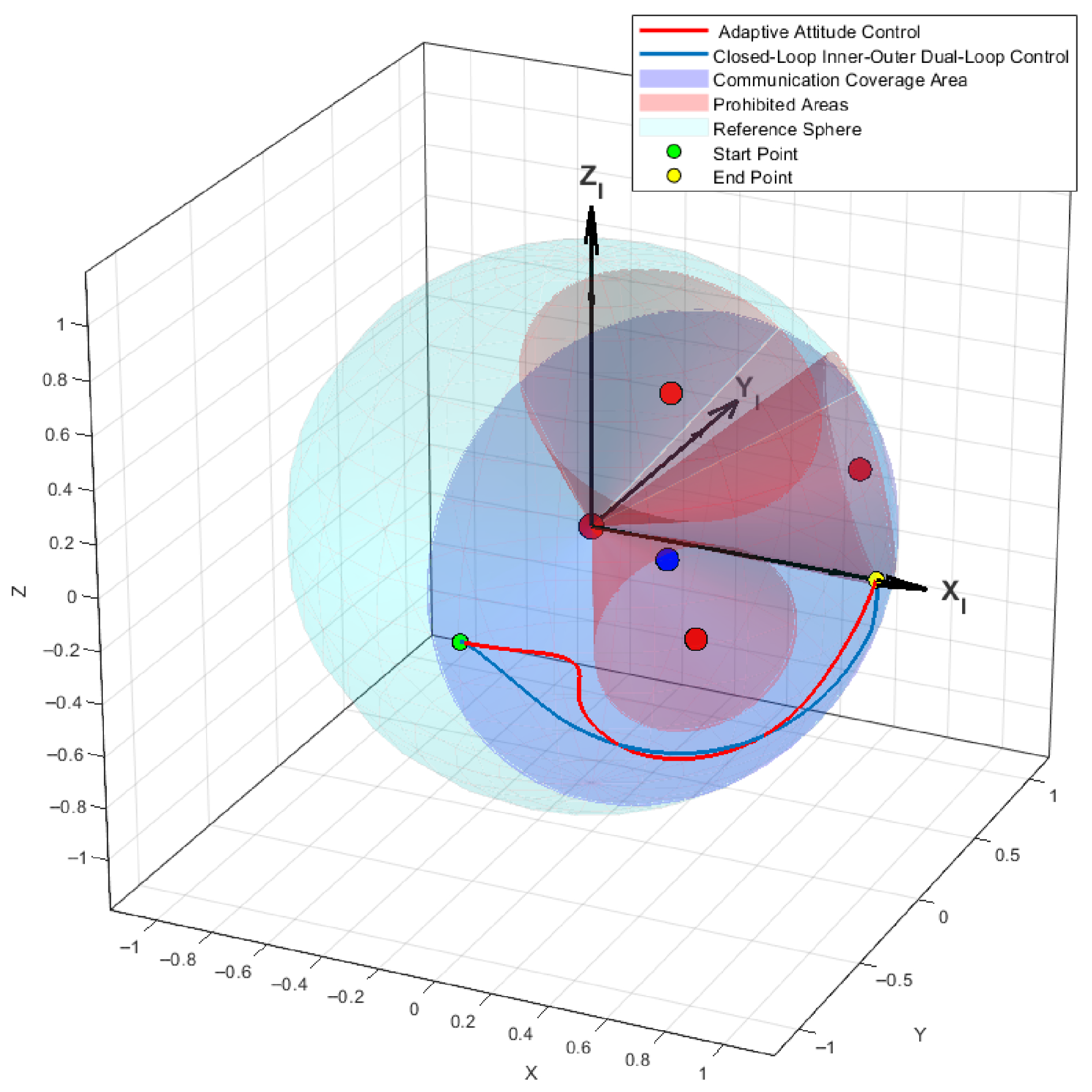
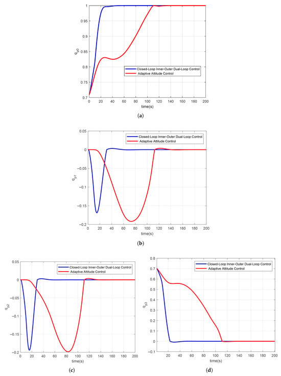
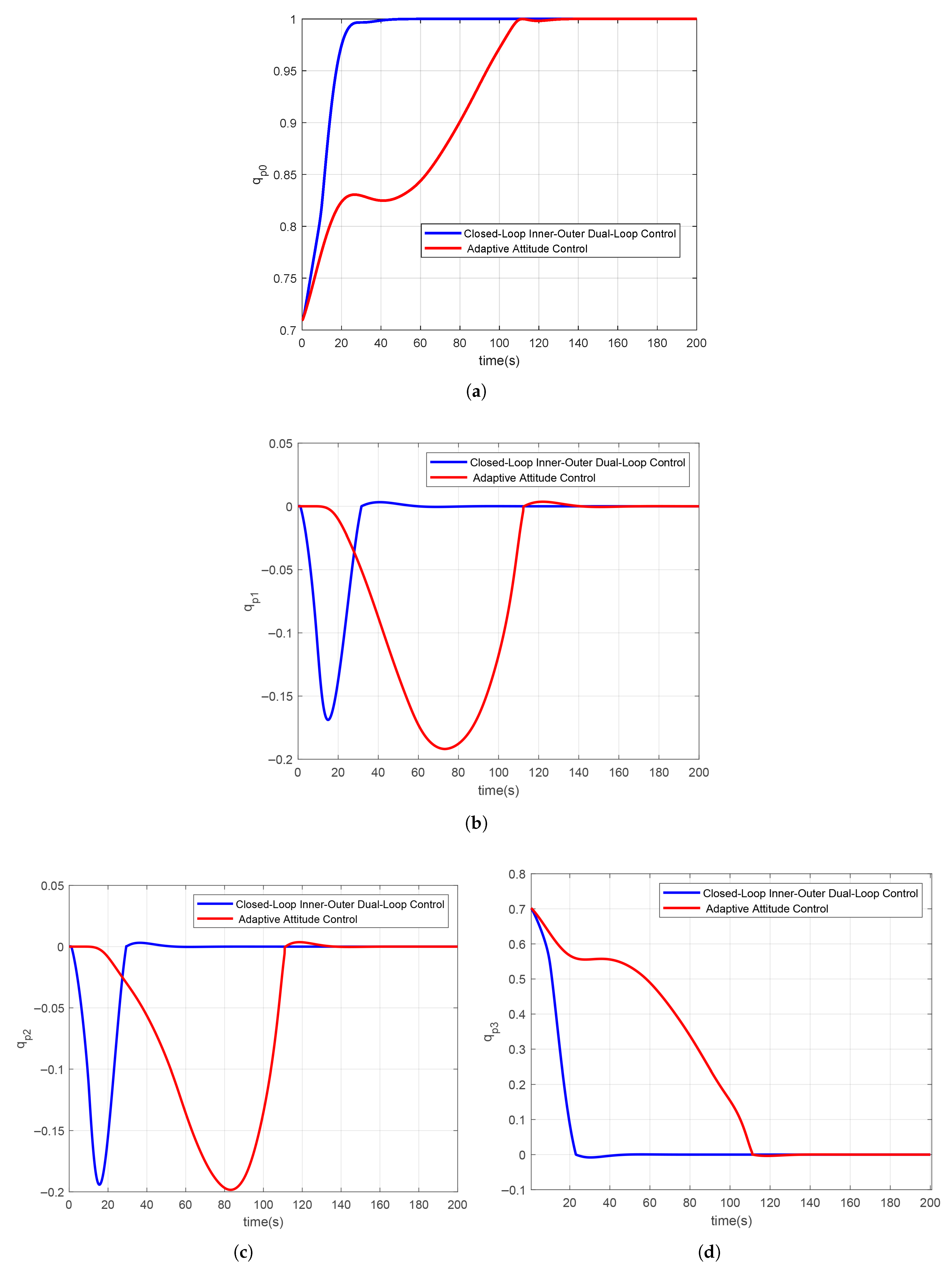
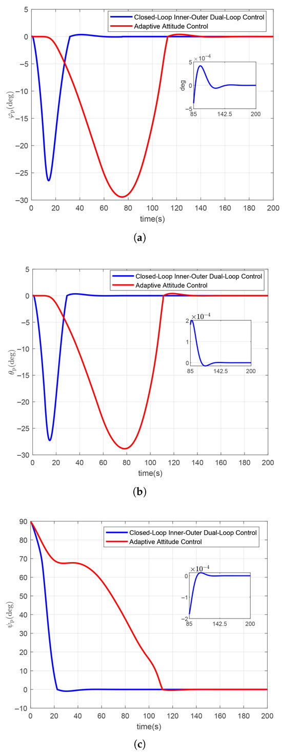
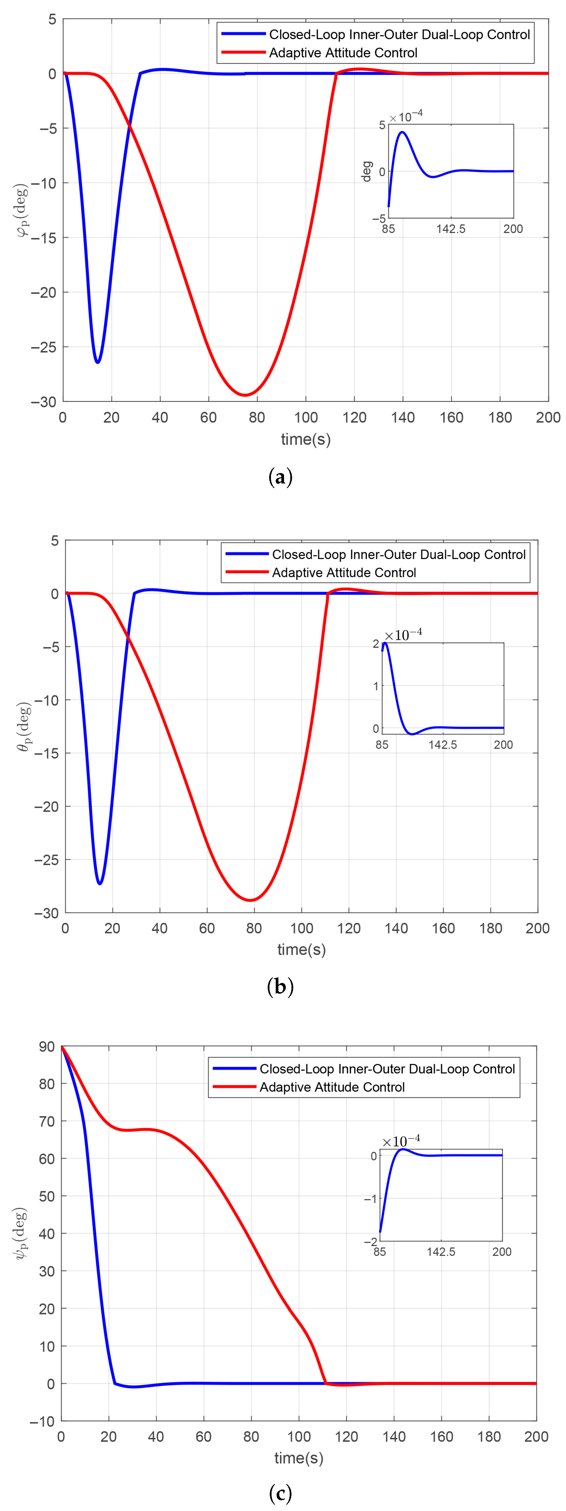
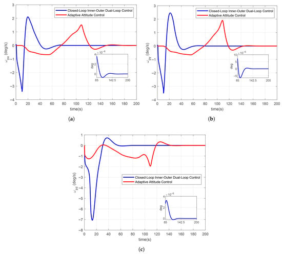
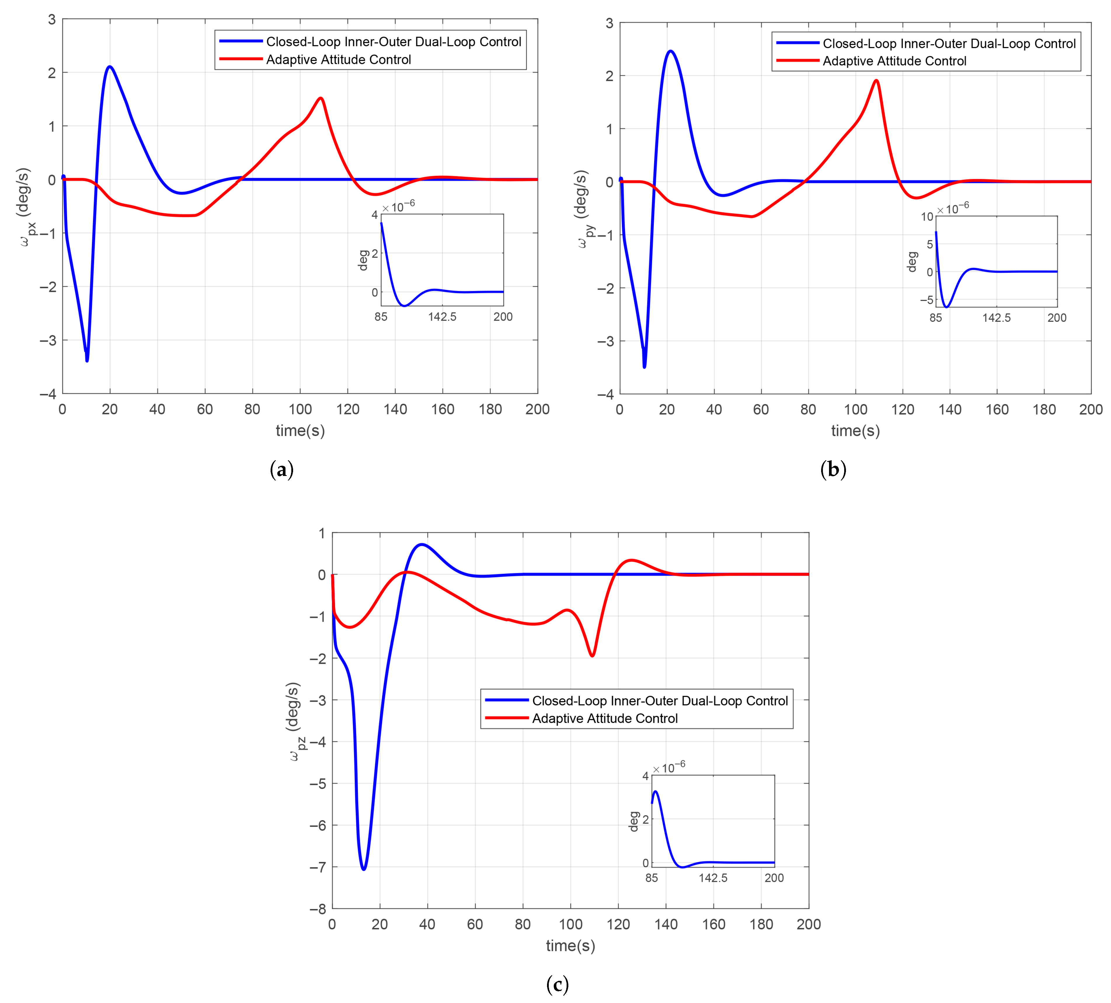
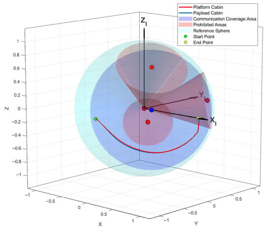
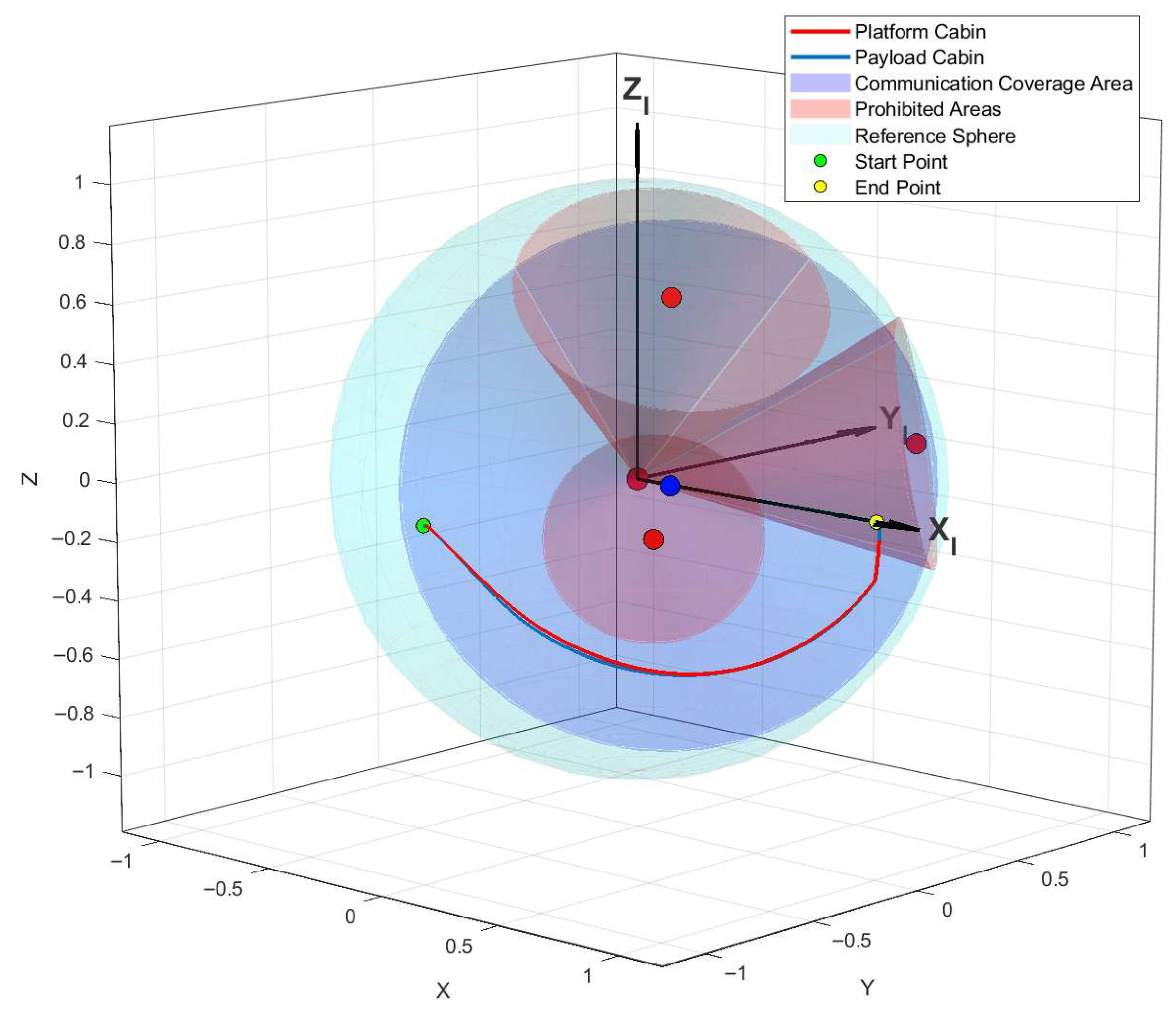
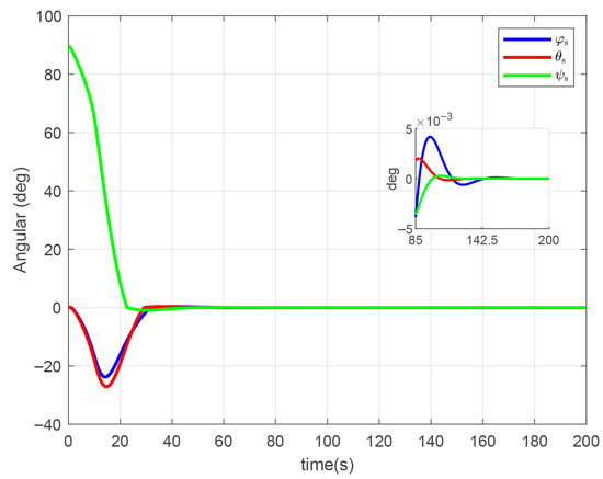
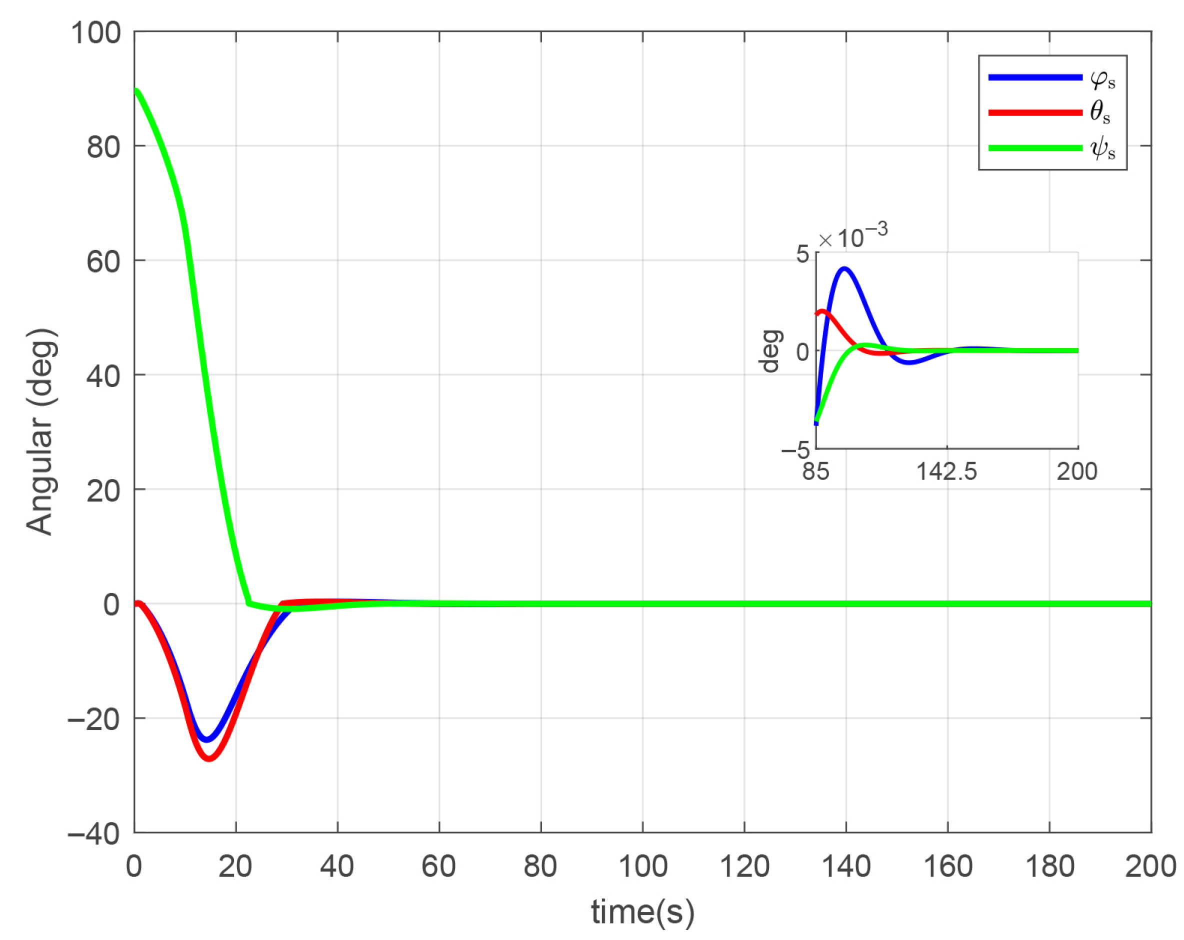
As illustrated in Figure 6, both the closed-loop inner–outer dual-loop control and the adaptive attitude control strategies successfully comply with the constraints during attitude maneuvers by steering clear of the prohibited zones. The blue dots in Figure 6 represent the centers of the communication area cones, while the red dots indicate the centers of the prohibited area cones. From Figure 7, Figure 8 and Figure 9, it is observed that under the closed-loop inner–outer dual-loop control architecture, the payload cabin attains the desired attitude within 70 s and fulfills the requirements for both pointing accuracy and stabilization accuracy within 85 s. On the other hand, the adaptive attitude control strategy takes 160 s to achieve , indicating a considerably slower convergence rate compared to the dual-loop framework. Additionally, Figure 6 shows that the trajectory generated by the dual-loop control maintains a wider safety margin from the prohibited region relative to that of the adaptive approach, suggesting improved operational safety.
Figure 6.
Payload cabin attitude trajectory diagram.
Figure 7.
(a) Payload cabin ; (b) payload cabin ; (c) payload cabin ; (d) payload cabin .
Figure 8.
(a) Payload cabin angle ; (b) payload cabin angle ; (c) payload cabin angle .
Figure 9.
(a) Payload cabin angular velocity ; (b) payload cabin angular velocity ; (c) payload cabin angular velocity .
4.3. Platform Cabin Control Outcome Analysis
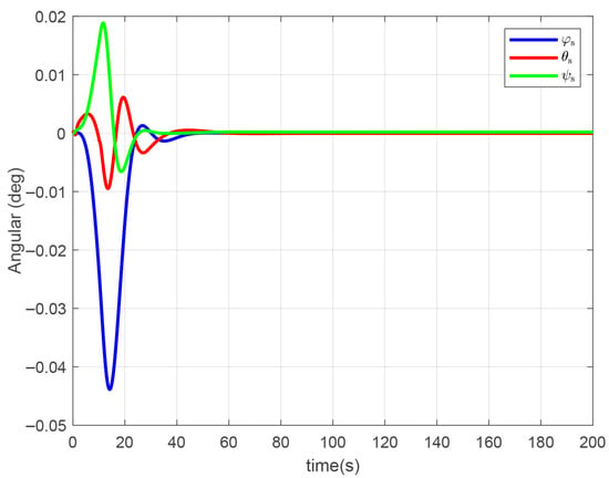
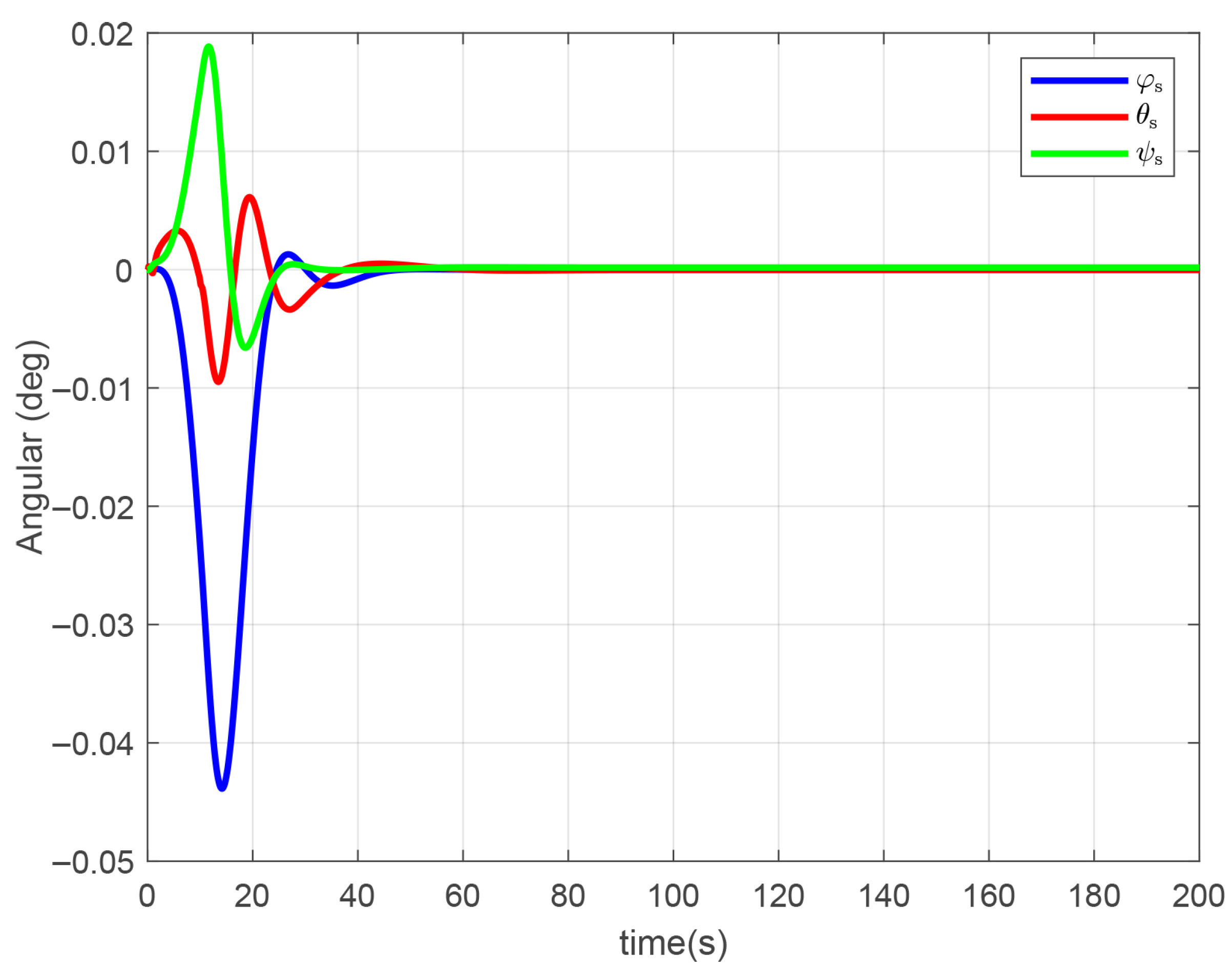
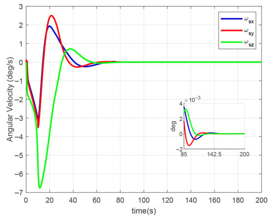
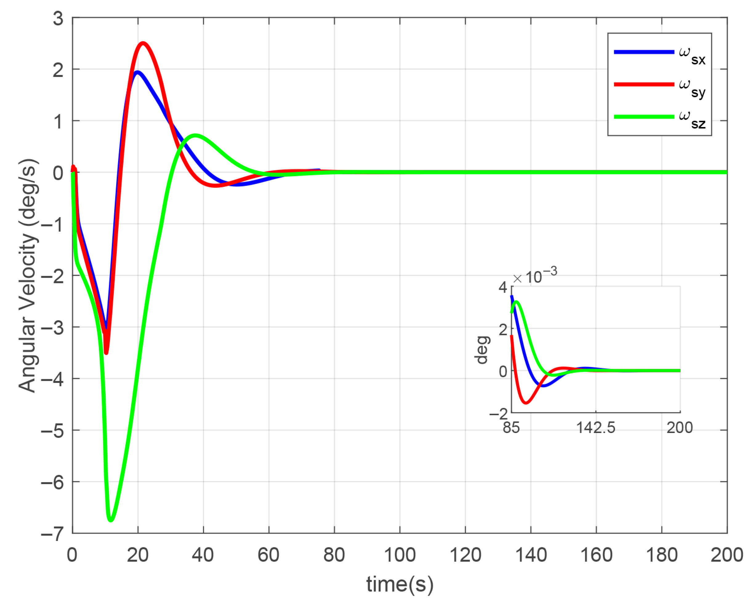
As evidenced in Figure 10, the QSMC law allows the platform cabin to accurately follow the attitude of the payload cabin, while keeping the communication axis steadily within the designated coverage zone, thus ensuring all constraint conditions are met. The blue dots in Figure 10 represent the centers of the communication area cones, while the red dots indicate the centers of the prohibited area cones. From Figure 11, it can be observed that the relative attitude angle error between the two cabins remains consistently small, staying below the previously discussed threshold of 0.57°. Therefore, the approximation of presented earlier is valid. Furthermore, Figure 12 and Figure 13 indicate that, after 85 s, the platform cabin complies with the required standards for both attitude pointing accuracy and stabilization performance.
Figure 10.
Dual-cabin attitude trajectory diagram.
Figure 11.
Relative attitude angle error between the two cabins.
Figure 12.
Platform cabin angle.
Figure 13.
Platform cabin angular velocity.
4.4. Magnetic Levitation Mechanism Collision Avoidance Control Outcome Analysis
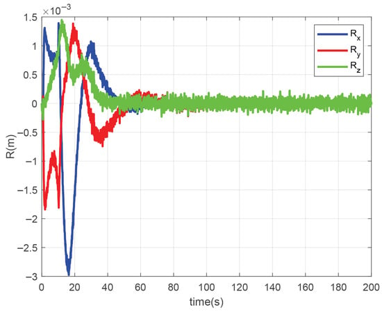
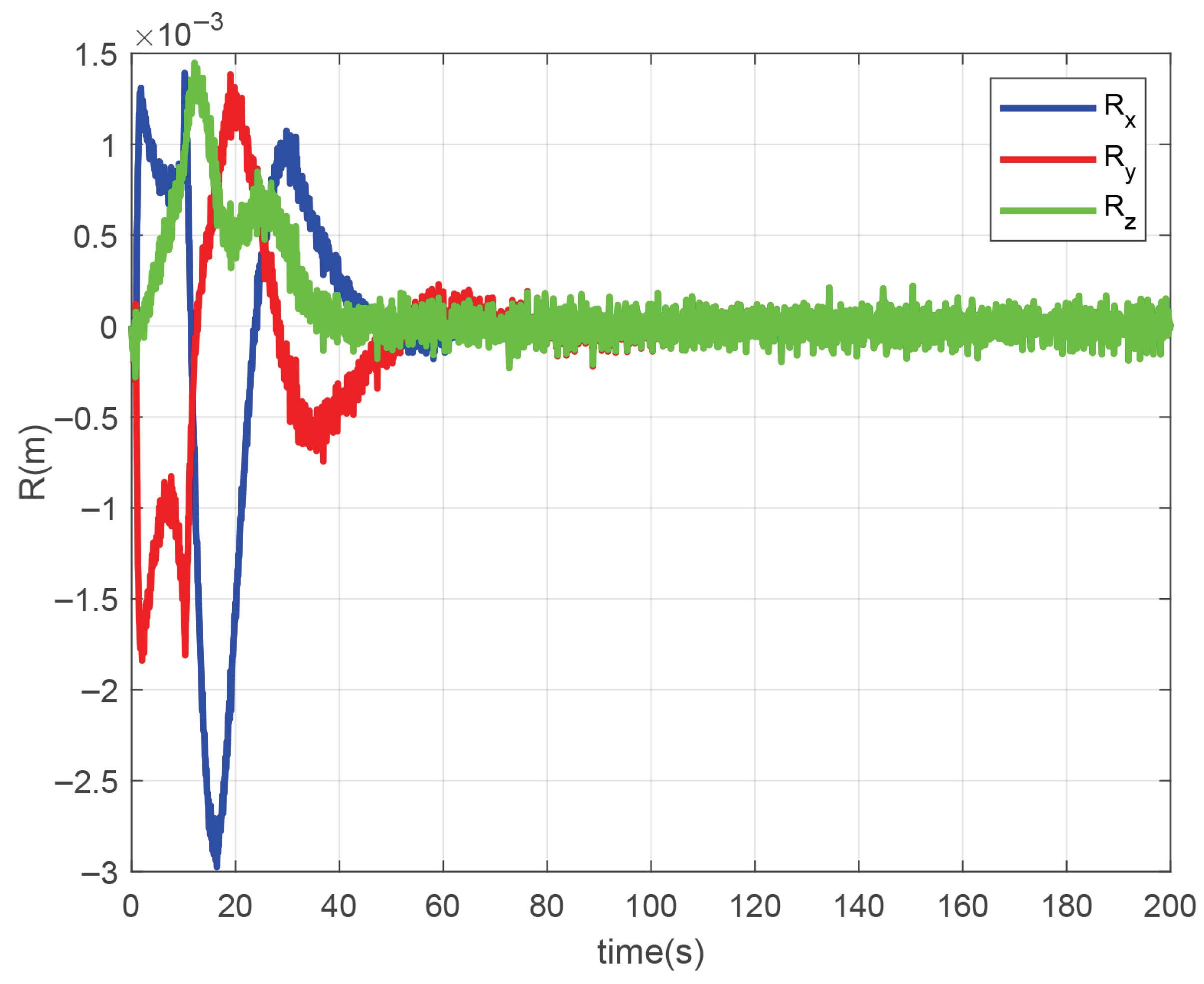
As depicted in Figure 14, the collision avoidance strategy implemented for the magnetic levitation mechanism successfully restricts the relative displacement variable within the predefined ±5 mm boundary, thereby safeguarding the structural integrity between the two cabins throughout attitude maneuvering operations.
Figure 14.
Relative displacement variable .
5. Discussion and Conclusions
This research develops a dynamic model capturing the coupled interactions within a dual-super spacecraft system, which includes a payload cabin, a platform cabin, and a non-contact magnetic levitation mechanism acting between them. A closed-loop inner–outer dual-loop control framework is applied to manage attitude maneuvers of the payload cabin. This method introduces a reference variable to achieve stability control in the outer-loop and implement constraint condition control by explicit reference governor (ERG) control in the inner-loop. The platform cabin is controlled in coordination to track the payload cabin’s motion. To avoid collisions between the two cabins during maneuvering, a collision avoidance strategy is incorporated into the magnetic levitation mechanism system, enhancing operational safety. Simulation outcomes confirm that both cabins successfully achieve their target attitudes while complying with all prescribed pointing accuracy specifications, indicating stable and safe performance of the overall spacecraft system. In comparison with adaptive attitude control, the proposed closed-loop inner–outer dual-loop framework shows improved convergence performance; however, it demands higher angular velocity and acceleration, which may exceed the actuation limits—including 12°/s for angular velocity, 5°/s2 for angular acceleration, and a 300 Nm output torque limit per CMG that bounds the overall system performance. This limitation merits further study in subsequent work.
Author Contributions
Conceptualization, J.X. and F.M.; methodology, J.X. and F.M.; software, J.X. and F.M.; validation, J.Q. and C.C.; formal analysis, J.Q. and C.C.; investigation, J.Q. and C.C.; resources, A.P. and F.M.; data curation, J.Q. and C.C.; writing—original draft preparation, J.X. and F.M.; writing—review and editing, J.X. and F.M.; visualization, J.Q. and C.C.; supervision, F.M. and A.P.; project administration, F.M. and A.P.; funding acquisition, A.P. and F.M. All authors have read and agreed to the published version of the manuscript.
Funding
This research was funded by the National Natural Science Foundation of China grant number 12162007.
Institutional Review Board Statement
Not applicable.
Informed Consent Statement
Informed consent was obtained from all subjects involved in the study.
Data Availability Statement
The original contributions presented in this study are included in the article. Further inquiries can be directed to the corresponding author.
Conflicts of Interest
The authors declare no conflicts of interest.
References
- Sedelinkov, A.; Nikolaeva, A.; Serdakova, V.; Khnyryova, E. Technologies for Increasing the Control Efficiency of Small Spacecraft with Solar Panels by Taking into Account Temperature Shock. Technologies 2024, 12, 207. [Google Scholar] [CrossRef] [Scilit]
- Eddine, B.J.; Boulanouar, K.; Elhassen, B. High-precision controller using LMI method for three-axis flexible satellite attitude stabilisation. Aeronaut. J. 2023, 127, 1308–1319. [Google Scholar] [CrossRef] [Scilit]
- He, G.; Cao, D. Dynamic modeling and attitude–vibration cooperative control for a large-scale flexible spacecraft. Actuators 2023, 12, 167. [Google Scholar] [CrossRef] [Scilit]
- Zhang, L.; Liu, Q.Z.; Fan, G.W.; Lv, X.Y.; Gao, Y.; Xiao, Y. Observer-based attitude maneuver control of flexible spacecraft: A parametric approach. Int. J. Control. Autom. Syst. 2024, 22, 2095–2107. [Google Scholar] [CrossRef] [Scilit]
- He, G.; Cao, D.; van der Heijden, G.H.M. Complicated nonlinear oscillations caused by maneuvering of a flexible spacecraft equipped with hinged solar arrays. Nonlinear Dyn. 2023, 111, 6261–6293. [Google Scholar] [CrossRef] [Scilit]
- Pedreiro, N. Spacecraft architecture for disturbance-free payload. J. Guid. Control. Dyn. 2003, 26, 794–804. [Google Scholar] [CrossRef] [Scilit]
- Trankle, T.; Pedreiro, N.; Andersen, G. Disturbance free payload flight system analysis and simulation methods. In Proceedings of the AIAA Guidance, Navigation, and Control Conference and Exhibit, Providence, RI, USA, 16–19 August 2004; p. 5875. [Google Scholar]
- Pedreiro, N.; Gonzales, M.; Foster, B. Agile disturbance free payload. In Proceedings of the AIAA Guidance, Navigation, and Control Conference and Exhibit, San Francisco, CA, USA, 15–18 August 2005; p. 5876. [Google Scholar]
- Zhang, W.; Zhao, Y.; Liao, H. Design of Active-Quiet Isolated and Master-Slave Coordination Controlled Dual-Super Satellite Platform. Aerosp. Shanghai 2014, 31, 7–11. [Google Scholar]
- He, L.; Daixin, W.; Jinjin, X.; Yi, X.; Chuang, Y.; Zhongxing, T. Chaotic Dynamics and Self-Recovery Control for a Magnetic-Levitation Spacecraft Under Single-Rod Fault. IEEE Trans. Aerosp. Electron. Syst. 2025, 61, 5788–5798. [Google Scholar]
- Qin, J.; Lei, M.; Shen, N. Analysis of the interception ability of electronic reconnaissance satellite on ground-based radars. In Proceedings of the 2021 6th International Conference on Intelligent Computing and Signal Processing (ICSP), Xi’an, China, 9–11 April 2021; pp. 698–701. [Google Scholar]
- Li, Z.; Zhao, L.; Liu, Y.; Chen, X.; Chen, H.; Zheng, F.; Zhang, Y.; Wang, D.; Li, J.; Liu, J.; et al. Autonomous mission planning method for optical imaging satellites based on real-time cloud cover information. Remote Sens. 2022, 14, 2635. [Google Scholar] [CrossRef] [Scilit]
- Mittermayer, J.; Gerhard, K.; Michelangelo, V. Multistatic dispersed swarm configurations for synthetic aperture radar imaging. IEEE Geosci. Remote Sens. Lett. 2022, 19, 4508805. [Google Scholar] [CrossRef] [Scilit]
- Yang, G.; Liu, X.; Guo, J. Research on Amount of Information of Multi-satellite Electronic Reconnaissance Based on Joint Probability Data. In Proceedings of the Association International Conference in Communications, Signal Processing, and Systems, Harbin, China, 14–17 July 2017; Springer: Singapore, 2017; pp. 1727–1734. [Google Scholar]
- Khamis, A.; Dawid, Z. Finite horizon optimal nonlinear spacecraft attitude control. J. Astronaut. Sci. 2020, 67, 1002–1020. [Google Scholar] [CrossRef] [Scilit]
- Eren, U.; Prach, A.; Koçer, B.B.; Raković, S.V.; Kayacan, E.; Açıkmeşe, B. Model predictive control in aerospace systems: Current state and opportunities. J. Guid. Control. Dyn. 2017, 40, 1541–1566. [Google Scholar] [CrossRef] [Scilit]
- Valencia-Palomo, G.; Rossiter, J.A.; López-Estrada, F.R. Improving the feed-forward compensator in predictive control for setpoint tracking. ISA Trans. 2014, 53, 755–766. [Google Scholar] [CrossRef] [Scilit] [PubMed]
- Wang, L.; Guo, Y.; Wu, L.; Chen, Q. Improved optimal steering law for SGCMG and adaptive attitude control of flexible spacecraft. J. Syst. Eng. Electron. 2015, 26, 1268–1276. [Google Scholar] [CrossRef]
- Yang, C.; Xia, Y. Interval uncertainty-oriented optimal control method for spacecraft attitude control. IEEE Trans. Aerosp. Electron. Syst. 2023, 59, 5460–5471. [Google Scholar] [CrossRef] [Scilit]
- Mammarella, M.; Lee, D.Y.; Park, H.; Capello, E.; Dentis, M.; Guglieri, G. Attitude control of a small spacecraft via tube-based model predictive control. J. Spacecr. Rocket. 2019, 56, 1662–1679. [Google Scholar] [CrossRef] [Scilit]
- Valencia-Palomo, G.; Rossiter, J.A. Novel programmable logic controller implementation of a predictive controller based on Laguerre functions and multiparametric solutions. IET Control Theory Appl. 2012, 6, 1003–1014. [Google Scholar] [CrossRef] [Scilit]
- Liu, Y.; Hu, Q.; Gang, F. Adaptive reduced attitude control for rigid spacecraft with elliptical pointing constraints. IEEE Trans. Aerosp. Electron. Syst. 2023, 59.4, 3835–3847. [Google Scholar] [CrossRef] [Scilit]
- Nicotra, M.; Emanuele, G. The explicit reference governor: A general framework for the closed-form control of constrained nonlinear systems. IEEE Control Syst. Mag. 2018, 38, 89–107. [Google Scholar] [CrossRef] [Scilit]
- Wang, P.; Zhang, X. Inverse optimal missile guidance law under constraints based on prescribed-time explicit reference governor. ISA Trans. 2022, 129, 395–404. [Google Scholar] [CrossRef] [Scilit]
- Costic, B.T.; Dawson, D.M.; De Queiroz, M.S.; Kapila, V. Quaternion-based adaptive attitude tracking controller without velocity measurements. J. Guid. Control. Dyn. 2001, 24.6, 1214–1222. [Google Scholar] [CrossRef] [Scilit]
- Wu, Q.; Liu, B.; Cui, N.; Zhao, S. Tracking control of a Maglev vibration isolation system based on a high-precision relative position and attitude model. Sensors 2019, 19, 3375. [Google Scholar] [CrossRef] [Scilit]

Disclaimer/Publisher’s Note: The statements, opinions and data contained in all publications are solely those of the individual author(s) and contributor(s) and not of MDPI and/or the editor(s). MDPI and/or the editor(s) disclaim responsibility for any injury to people or property resulting from any ideas, methods, instructions or products referred to in the content. |
© 2025 by the authors. Licensee MDPI, Basel, Switzerland. This article is an open access article distributed under the terms and conditions of the Creative Commons Attribution (CC BY) license (https://creativecommons.org/licenses/by/4.0/).