Abstract
Bellows compensators are critical components in pipeline systems, designed to absorb thermal expansions, vibrations, and pressure reflections. Ensuring their operational reliability requires accurate prediction of the stress–strain state (SSS) and stability under internal pressure. This study presents a comprehensive mathematical model for analyzing corrugated bellows compensators, formulated as a boundary value problem for a system of partial differential equations (PDEs) within the Kirchhoff–Love shell theory framework. Two numerical approaches are developed and compared: a finite difference method (FDM) applied to a reduced axisymmetric formulation to ordinary differential equations (ODEs) and a finite element method (FEM) for the full variational formulation. The FDM scheme utilizes a second-order implicit symmetric approximation, ensuring stability and efficiency for axisymmetric geometries. The FEM model, implemented in Ansys 2020 R2, provides high fidelity for complex geometries and boundary conditions. Convergence analysis confirms second-order spatial accuracy for both methods. Numerical experiments determine critical pressures based on the von Mises yield criterion and linearized buckling analysis, revealing the influence of geometric parameters (wall thickness, number of convolutions) on failure mechanisms. The results demonstrate that local buckling can occur at lower pressures than that of global buckling for thin-walled bellows with multiple convolutions, which is critical for structural reliability assessment. The proposed combined approach (FDM for rapid preliminary design and FEM for final verification) offers a robust and efficient methodology for bellows design, enhancing reliability and reducing development time. The work highlights the importance of integrating rigorous PDE-based modeling with modern numerical techniques for solving complex engineering problems with a focus on structural integrity and long-term performance.
Keywords:
bellows compensator; stress-strain state; partial differential equations; finite difference method; von Mises criterion; buckling analysis; axisymmetric shell MSC:
74K25; 65N30; 65N06; 74G60; 35Q74
1. Introduction
In modern mechanical engineering and power engineering, the tasks of compensating for thermal deformations, vibrations, and pressure reflections in pipeline systems are of global importance, since pipelines are an integral part of industrial complexes, transport routes, cooling systems, and the supply of aggressive media [1]. Bellows expansion joints, which are corrugated metal or composite rings, are able to flexibly adapt to axial, lateral, and angular movements, ensuring the tightness and durability of main and local connections [2]. Their behavior is determined by the complex interaction of shell mechanics, nonlinear deformations, and the loss of stability, which determines the high relevance of research not only for the economics of operation but also for the construction of mathematically substantiated calculation methods with a guarantee of safety and accuracy [3,4].
To solve such problems, analytical approaches are traditionally used, including the linear analysis of shells under internal pressure and the use of classical simplifications of geometry. Early work, such as NASA reports [5] and Hansel models [6], used linear analytics and a preliminary nonlinear filter to estimate acceptable bellows configurations and cut out unstable models. These approaches provided extremely fast estimates but were limited to being applicable only to configurations with sufficiently smooth geometry and low deformations and ignored the local instability effects inherent in corrugated shapes [7].
The development of computer technology and software systems made it possible to move to numerical methods, mainly to the finite element method, which became a standard in engineering practice. Studies such as the LS-DYNA analysis performed in [8] demonstrated the modeling of the mechanical characteristics of U-shaped bellows joints under various loads—axial tension, compression, cyclic loading, and bending—with experimental verification of the results. A linear dependence of energy absorption on the number of corrugations was shown, which confirms engineering intuition, but FEM analytics is distinguished by significant computational complexity and the labor intensity of preparing geometries and meshes, especially when it is necessary to take into account small parts and thin walls [9,10].
Other studies, such as [11], used ABAQUS to simulate the symmetrical cyclic processes of tension and compression of corrugated skirts, analyzing the manifestations of strain hardening, microstructural mechanisms, and the effect of martensite on bellows response stability. These studies provided a practical foundation for performance, but traditional FEM models also have drawbacks in the form of the need for accurate material accounting, nonlinear effects, and long calculation times [12].
At the same time, methods based on finite differences and simplified geometric models were developed. Separate reports [13,14] indicated that numerical methods including finite difference (FD) and numerical integration could be used to quickly assess the stability of bellows, especially in symmetrical or approximate cylindrical systems, allowing for estimates at the preliminary design stage. Such methods, being less accurate in complex geometries, are superior to FEM in speed, especially if the design has strict axisymmetry [15].
Among other approaches presented in the modern literature, one can single out studies based on the contact nonlinearity of multilayer bellows, taking into account the closure of corrugations. Such works, for example, by T. Man [8], considered the effect of contact between layers, modeling it using specialized interface conditions in FEM models. Thanks to this, it is possible to more accurately predict the behavior of bellows in modes close to buckling, but such models require high computational resources and the complex adjustment of contact parameters [16].
There are also new approaches in the field of structures inspired by origami bellows, where the authors [17] proved that small changes in geometry, for example, slits at the tops of folds, can significantly (by an order of magnitude) change the rigidity of the structure and its response to compression. These studies open up the potential for the design of highly non-standard composite shapes, but they are still too exotic for modern industrial bellows and require transformation into engineering-relevant models [18].
Also, in numerical methods, the direction of high-order compact schemes is developing, in particular, high-order schemes of compact finite-difference approximation (HOC), used in problems with smooth geometry and strict accuracy requirements [19]. Such schemes give a third or even fourth order of convergence with a small approximation pattern, but, in the context of bellows, they are rarely used due to the difficulty of taking into account boundary conditions and geometric features, especially when the shape of the corrugation is complex or includes curvatures along two axes [20].
Another promising way is Smoothed FEM [21], which combines the advantages of mesh and mesh-free approaches by modifying the deformation field. They allow you to improve the accuracy and stability of the solution on coarse meshes, especially under conditions of nonlinearity or deformation concentration. However, their application to the mechanics of shells and specifically to corrugated forms of bellows has not yet become standard: the current results, although promising, need further research [22].
Existing approaches thus demonstrate a variety of methods: FEM provides accuracy and flexibility but requires resources and training; finite difference methods provide speed and simplicity in axisymmetric geometry but are limited by accuracy and geometric versatility. Complex high precision or smoothed methods are still not adapted to the specifics of the bellows shape [23].
The relevance and novelty of this study are due to the need to develop effective and accurate methods for calculating bellows compensators that combine computational efficiency for engineering design and mathematical rigor necessary for the reliable prediction of limit states. Existing methods are either too resource-intensive (full-fledged FEM) or not accurate enough for complex corrugation geometries (simplified analytical models). The novelty of the work lies in the combined application of two numerical methods (FDM and FEM) to a single strict PDE formulation of the problem for the Kirchhoff–Love shell. This allows for the mutual verification of results and the use of the advantages of each method at different stages of design: rapid parametric analysis [24] using FDM and detailed verification using FEM. In addition, the paper proposes and implements an implicit symmetric second-order difference scheme adapted for the axisymmetric reduction in the PDE system and conducts a comprehensive analysis of both the strength criterion (Mises) and the stability criterion, revealing the mutual influence of geometric parameters on various failure mechanisms [25]. In addition, the work offers an integrated approach to assessing the reliability of bellows based on a joint analysis of strength and stability, which makes it possible to identify critical operating modes and optimize geometric parameters to increase the service life.
The purpose of the study is to formulate a model of the stress–strain state (SSS) and stability of corrugated bellows expansion joints in the form of a PDE problem to implement its numerical solution through the finite difference method with the analysis of convergence and stability. Another purpose is to create a FEM model of variational formulation in parallel, to compare the results of both methods, to conduct a parametric analysis of geometric and physical factors, to identify the mechanism of buckling, and to determine critical pressures. This approach is aimed at improving the quality and reliability of engineering calculations of bellows expansion joints while maintaining the efficiency and versatility of the method [26].
The main objectives of the study are as follows:
- −
- To write out a strict mathematical formulation of the problem for PDE with boundary conditions corresponding to different ways of fixing the bellows.
- −
- To develop and implement a numerical algorithm based on an implicit symmetric second-order difference scheme for solving a reduced PDE system.
- −
- To build a FEM model in a variational formulation and perform calculations in Ansys.
- −
- To conduct a convergence analysis and comparison of methods on test and engineering tasks.
- −
- To perform parametric studies of the effect of geometry and material on critical pressure and stability.
The structure of the work is organized as follows. Section 2 provides a rigorous mathematical formulation of the stress–strain state and stability problem of corrugated bellows expansion joints in terms of partial differential equations, including the formulation of boundary conditions and the introduction of axisymmetric simplifications. Section 3 focuses on the implementation of finite differences for reduced formulation, including derivative discretization, numerical circuit selection, and stability analysis. Section 4 presents the formulation of the problem in the variational form and its numerical implementation by the finite element method, which allows you to take into account complex geometry and various variants of consolidation. Section 5 provides a comparative analysis of the convergence and stability of the methods, as well as an assessment of computational efficiency. Section 6 contains the results of numerical experiments, including the determination of critical pressures according to the yield criterion and the buckling condition, as well as the influence of geometric and mechanical parameters on the behavior of the structure. Section 7 discusses the results from the perspective of engineering practice and numerical methodologies for PDEs. Section 8 concludes the work by summarizing the research carried out, formulating conclusions and outlining directions for further research.
2. Clarification of the Mathematical Formulation and Physical Assumptions
In order to conduct a rigorous numerical analysis that corresponds to the topic of numerical methods for PDE, it is necessary to start with a clear mathematical formulation of the initial engineering problem [26]. A bellows compensator, which is a thin corrugated shell of rotation, can be described within the framework of the linear theory of Kirchhoff–Love elastic shells (KL) as a two-dimensional elastic surface in three-dimensional space loaded with internal pressure (Figure 1).
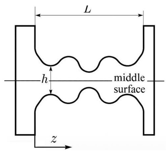
Figure 1.
The geometrical scheme of the corrugated bellows for the problem formulation.
2.1. Clarification of the Mathematical Formulation and Physical Assumptions
The physical object being modeled is a corrugated metallic bellows compensator, which is a thin-walled elastic shell of a revolution subjected to internal pressure. The bellows is characterized by a periodic geometry composed of a sequence of convolutions, each defined by a corrugation height W, the wall thickness h, and the mean radius R. The total axial length of the bellows is denoted as L, and the coordinate z is measured along the longitudinal axis of symmetry. These parameters are depicted in Figure 1.
The mathematical model is developed within the Kirchhoff–Love shell theory, assuming the following physical considerations:
- “The material is homogeneous, isotropic, and linearly elastic, with Young’s modulus E and Poisson’s ratio vi”;
- “The shell thickness h is much smaller than the mean radius R (thin shell assumption, h/R << 1)”;
- “The displacements are small compared to the overall dimensions, allowing linearization of the strain-displacement relations”;
- “The transverse normals remain straight and normal to the mid-surface after deformation (Kirchhoff-Love kinematic hypothesis), i.e., shear deformation through the thickness is neglected.”
Under these assumptions, the unknown fields are the tangential displacement ut(s), the normal displacement w(s), and the rotation of the normal φt(s) along the meridian coordinate s. The governing equations are the equilibrium equations of forces and moments on the mid-surface, expressed in tensor form as a system of second-order linear partial differential equations (PDEs):
where N, M, and Q are the membrane force, bending moment, and shear force tensors, respectively, and qt and qn represent external tangential and normal loads.
The constitutive relations link stress resultants to strains via
where Cm and Cb are the membrane and bending stiffness tensors depending on E, ν, and h.
The boundary conditions correspond to clamped, hinged, or mixed supports, defined by either prescribed displacements (Dirichlet conditions) or surface tractions and edge moments (Neumann conditions).
Finally, in the axisymmetric reduction, all quantities depend only on the meridional coordinate s, and the PDE system reduces to a first-order matrix differential system for {ut, w, φt, Ntt, Qt, Mtt}, as used in Section 2.4.
The equations in Section 2.4 thus constitute the complete mathematical formulation of the problem in strong and weak forms, directly derived from the above physical and geometrical assumptions.
In the classical formulation, the problem is reduced to a system of second-order partial differential equations (PDEs) that reflects the balance of forces and moments on the median surface of the shell, taking into account its curvature, thickness, elastic properties of the material, and external load. These equations are written in the tensor form for membrane and flexural deformations and are generally an elliptic PDE system [27].
Figure 2 shows an axisymmetric geometric model of the bellows compensator under study, which is the basis for the mathematical formulation of the problem. Figure 2 was constructed on the basis of a parametric description of the bellows meridian using real geometric parameters typical of industrial expansion joints: the average radius (R) was 50 mm, the corrugation height (W) was 12 mm, and the wall thickness (h) was 3 mm. The diagram reflects the key geometric parameters that determine the stiffness characteristics [28] and the stability of the structure:
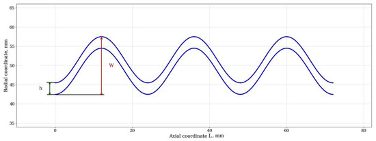
Figure 2.
The schematic representation of the geometry of a corrugated bellows with the designation of key parameters: W is the height of the corrugation, h is the wall thickness, L is the total length of the bellows plotted along the abscissa axis, and R is the average radius.
- -
- The height of the corrugation (W) directly affects the compensating capacity of the bellows and its compliance.
- -
- The wall thickness (h) is a critical parameter that determines strength and the resistance to internal pressure.
- -
- The average radius (R) and overall length (L) define the main dimensions and ratios of the structure.
This visualization highlights the complexity of the geometry that must be considered when building finite difference and finite element models. The periodic profile necessitates the use of methods that can correctly approximate areas with a high curvature [29].
Physically, the problem is to find the displacement fields and angular rotations of the normal that ensure the equilibrium of the shell under given boundary conditions. Mathematically, it is a boundary value problem [30] for a PDE system with Dirichlet and/or Neumann conditions on the contour of the median surface.
In this paper, a complete two-dimensional formulation of the problem on an arbitrary surface is first considered. This makes it possible to isolate the fundamental PDE operators, define functional spaces, and formulate the problem in a variational form suitable for the finite element method [31]. Then, taking into account the axisymmetry of shape and load, a reduction to a one-dimensional formulation along the meridian is carried out, which results in an ODE system that is a convenient finite difference and finite element sample (FDM).
This two-stage approach allows for, on the one hand, emphasizing the versatility and mathematical rigor of the formulation as a problem for PDE. On the other hand, it allows you to effectively implement a numerical solution for a specific engineering case [32].
The following subsections of Section 2 are set out as follows:
- Description of the geometry and kinematic model of the shell (Section 2.1);
- Constitutive relations and parameters of the material (Section 2.2);
- Setting boundary conditions (Section 2.3);
- Balance equations in strong and weak forms (Section 2.4 and Section 2.5);
- Reduction in the axisymmetric case and notations in the form of TAC (Section 2.6);
- Scaling and introduction of dimensionless parameters (Section 2.7);
- Procedure for calculating equivalent stresses and stability analysis (Section 2.8 and Section 2.9);
- Final reduction in all elements into a complete statement (Section 2.10).
2.2. Geometry, Displacement Field, and Kinematics (Kirchhoff–Lyava Variant)
Let S Ρ3 be the smooth median surface of the shell with the unit normal n and the first and second fundamental forms a and b (respectively, the metric tensor and the curvature tensor). The thickness of the shell is h << rad(S). The material is isotropic linear elastic with Young’s modulus E and Poisson’s ratio ν.
The displacement field of the median surface is represented as
where ut is the tangent displacement, ω is the normal displacement. In the classical Kirchhoff–Love theory, the “material normals” remain normal after deformation, i.e., the transverse displacements on the median surface are zero. This results in a kinematic coupling for the rotation vector of the normal φ (tangent vector):
where K is the first-order differential operator (explicitly through the surface gradient and curvature). In the KL hypothesis, transverse shears are excluded from the set of independent variables, and the shear vector Q arises as a Lagrange factor in the variational arrangement of the balance of moments (see below).
Deformation measures. For KL shells, two tensor strain measures on S are convenient:
Membrane deformations (change in metric) ε are linearly dependent on ut and ω through the surface gradient ∇σ and curvature b.
Flexural deformations (change in curvature) κ are linearly dependent on φ (or on ω and ut when substituting a KL bond).
Without fixing sign conventions (they differ in the literature), we will use abstract notation
where ε1 and ε2 are first-order linear surface differential operators.
2.3. Power Factors and Constitutive Relations
Let N be the tensor of membrane forces (per unit length), M be the tensor of bending moments (per unit length), and Q be the vector of shear forces (per unit length) on the median surface [33].
For an isotropic KL shell, the constitutive laws have a standard form
where “:” is double coagulation (action of the fourth rank on the second) and membrane and flexural stiffness:
C is an isotropic plane constitutive tensor (Lamé matrix for a plane stress state) with components that generate a standard bond:
here, the indices α and β run two tangent directions to S, a tra(⋅) is the trace relative to a.
In the KL variant, there are no independent constitutive relations for Q (transverse shears are excluded by kinematics), and Q is determined from the balance equations.
2.4. Loads and Boundary Conditions
Internal pressure p acts normally to the surface: surface load
On the part of the D = S boundary ∂, the following can be specified:
Kinematic (Dirichlet) conditions in the GD section: clamping/hinge defines combinations
(complete embedding) or weakened conditions (for a hinge, there is prohibition of movement, free bending).
Force (Neumann) conditions in the HN section: edge stresses and moments (contact forces at the edge) are set
where ν is the exterior normal unit in the tangent plane to the boundary G.
2.5. Balance of Forces and Moments on the Surface (Strong Form)
In the tensor-operator form, the equilibrium equations of the KL shell are written as
where q|| and qn are the tangent and normal components of the external load q, mext is the external distributed moments (in our case, there are none). The div operator S is the surface divergence acting on the tensor/vector fields on S.
Substitution of constitutive bonds and kinematic operators ε1, ε2, and K generates a closed system of second-order linear PDEs with respect to (ut, ω) (and with the preservation οϕ φ, there is a mixed first/second-order system), which is elliptic with smooth geometry and standard fixations [34].
2.6. Variational (Weak) Staging and Functional Spaces
We will denote
where τ is the tangent edge vector. Then, the natural space of the test functions is
In the present work, this functional space is defined explicitly as
i.e., the space of admissible displacement fields on the mid-surface S that satisfy the prescribed kinematic (Dirichlet) boundary conditions.
This definition follows the standard variational framework for the Kirchhoff–Love shell model and ensures consistency of the weak formulation with the general Sobolev space setting.
The energy bilteag form for the KL shell is
and the functionality of the right part is
where φ(z) is the edge variation in the rotation angle consistent with KL kinetics. For the weak positioning, we will find
In standard fights on A and D (positive definiteness on the corresponding subspaces) and correct Dirichlet conditions, the form a(⋅,⋅) is coercive, which ensures the uniqueness and stability of the solution (according to Lax–Milyram) in a linear formulation.
2.7. Axisymmetric Geometry and Reduction in TAC
Let the shell be the surface of rotation obtained by rotating the meridian (x(s), ρ(s)) about the x-axis, where s ∈ (0, L) is the arc coordinate of the meridian. In the local basis (t, θ, and n) (meridian tangent, parallel tangent, and normal), in an axisymmetric problem, all fields depend only on s
where the indices t and θ refer to the meridian and parallel.
The balance equations in the component form are reduced to a system of ordinary first-order differential equations for U(s):
where the matrix G(s) and the vector g(s) depend on the meridian geometry (x,ρ), the curvatures κτ(s) and κθ(s) − 1/r(s), and the material parameters (E, ν, h). The relationships between (ut, ω, φτ) and (Nt, Qt, Mt) are defined by local constitutive laws (Section 2.2) with the reduction in two-dimensional tensors to axisymmetric components (t, θ).
Boundary conditions on s = 0 and s = L are specified according to the type of support:
Clamped: ut = 0, ω = 0, φτ = 0;
Hinge (simply supported by bend): ut = 0, ω = 0, Mt = 0;
Mixed support: An appropriate combination of displacement conditions and moments/shear forces.
2.8. Scaling and Dimensionless Options
For numerical analysis, it is convenient to switch to dimensionless quantities by choosing characteristic scales:
Here, R0 is the characteristic radius of the shell. The eight variables of the coefficients in the ODE/PDE are grouped through the thinness and geometric curvature of κtR0 and κθP0, which facilitates the analysis of discrete system conditionality and the interpretation of convergence.
2.9. Post-Criteria Processing: Equivalent Stresses and Yield Criterion
To estimate the ultimate pressure, a stress tensor on the face surfaces (inner/outer) of the thickness h layer is used. With a known set of force factors (N and M), stresses are normally restored at a distance of ±h/2 from the median surface, after which the deviator and equivalent Mises stress σρεθ are calculated.
This procedure is related to the PDE solution in that the N, M, and ω fields are derived from the weak/strong form solution and then locally post-processed.
2.10. Linearized Stability Analysis (Adjacent Forms of Equilibrium)
To estimate buckling, a standard approach to problem for a linearized operator is applied. Let (ut and ω) be a stationary solution under load p. We consider perturbations (δut and δω) and linearize the weak form:
where λ is the load multiplier (eigenvalue), b(⋅,⋅) is the bilteag form generated by geometric stiffness (depending on the stress state under load p). The critical load corresponds to the minimum λσγ with which a non-trivial solution exists (an adjacent form of equilibrium). In the axisymmetric case, this procedure is reduced to an intrinsic task for ODE systems, and for a full ZR formulation, to an eigenproblem on the S surface.
2.11. Result of the Formulation
Therefore, the original engineering problem is fully described as a boundary value problem for a system of linear elliptic PDEs (the KL shell on surface S under normal load p) with the following key components [35]:
Not known: (ut and ω) (and/or φ if mixed).
Strong form: Balance of membrane forces, shear forces, and moments by five with normal load p.
Weak form: Energy production in spaces H1(S) × H2(S) (for KL) with a coercive bilinear form.
Boundary conditions: Dirichlet/Neumann for displacements/edge forces and moments corresponding to embedding, hinge, and mixed fasteners.
Reduction in TAC: In axisymmetry, a first-order system along the arc coordinate of the meridian with standard two-point boundary conditions.
Post-processing: Computation of equivalent stresses (Mises) and linearized stability analysis (eigenproblems).
This formulation sets the stage for Section 3, where we will detail finite difference discretization (including explicit meridian derivative approximation patterns, schematic matrix properties, and stability/error analysis), as well as Section 4, where we will write down the variational FEM form and discuss practical implementation and convergence control.
3. Finite Difference Method for PDE Solution
After the initial problem of the stress–strain state of the bellows compensator was formulated as a boundary value problem for the PDE system on the median surface of the shell [36] and then reduced in the axisymmetric case to the ODE system along the meridian, there is a need to construct an effective numerical method. The choice of the finite difference method (PH) for this formulation is due to the regular geometry of the meridian line, the possibility of uniform division of the design interval, and the simplicity of implementing high-precision approximations [37]. In this case, the sampling used in axisymmetry is a projection of a complete two-dimensional scheme for a PDE onto a single spatial variable.
In the finite difference formulation developed in this section, the system of PDEs being approximated originates directly from the Kirchhoff–Love shell equations described in Section 2.4, which represent the balance of membrane forces, bending moments, and shear forces on the median surface of the bellows. In the strong form, this system can be written symbolically as follows:
where N and M are the membrane and bending stress resultants, Q is the transverse shear force vector (eliminated through the Kirchhoff–Love kinematic constraint), and q represents the external load due to internal pressure acting normally to the surface. These PDEs are coupled through the constitutive relations:
where A and D are the membrane and flexural stiffness tensors, and the strain measures ε and κ depend on the displacement field components ut(s) and ω(s) and their surface derivatives.
N = A:ε, M = D:κ,
Under the assumption of axisymmetry, all field quantities depend only on the meridional coordinate s, and the above PDE system reduces to a coupled system of first-order ordinary differential equations for the generalized displacement vector U = [ut,w,jt]T:
where the matrices G(s) and H(s) include geometric curvature terms and material parameters, and f(s) accounts for the internal pressure loading. This reduced system forms the basis for the finite difference discretization described below.
Therefore, the finite difference method implemented in this section is not a generic numerical procedure but a structured approximation of the axisymmetric reduction in the full Kirchhoff–Love shell PDE system presented in Section 2, preserving the physical meaning of stress and moment equilibrium in each discrete node along the bellows meridian.
3.1. Spatial Discretization
Let the shell meridian be parameterized by the arc coordinate s ∈ [0, L]. A uniform grid is introduced in this segment
where δ = L/N is the discretization step. At each node si, the values of the state vector components are defined
which are interconnected by a system of linear TACs derived from a reduced axisymmetric form of the PDE (Section 2.6).
3.2. Difference Approximations
To approximate the first derivatives of s, the central difference in the second order is used:
and for the second derivatives
These approximations preserve the second order of accuracy on a uniform mesh and agree well with the smoothness of solutions in a linear elastic formulation.
In the implicit symmetric scheme used in the work, the TAC system, written in the form of
is approximated by the Crank–Nicholson formula
which makes it possible to achieve A-stability when integrated at the s coordinate and reduce the accumulation of error at the large N.
3.3. Implementation of Boundary Conditions
The boundary conditions at the i = 0 and i = N nodes are overlaid directly on the components of the U state vector. For example
- When pinched: Ui = 0, ω = 0, φτ = 0;
- With articulation: ui = 0, ω = 0, Mt = 0;
- In mixed: Displacements and/or moments are recorded according to the physical model.
In the implicit scheme, boundary conditions are included in the global system of algebraic equations as rigid connections (the method of exclusion or the method of large coefficients).
3.4. Formation of a Discrete System
Discretization of the entire system by s leads to a block-strip matrix of dimension coefficients 6(N + 1) × 6(N + 1). The block structure reflects the physical connectivity of the components U through equilibrium equations and constitutive relationships.
A compact matrix form was used for implementation:
where Ai, Bi, and Ci are matrices of local coefficients depending on the geometry and parameters of the material; Fi is the vector of the right part, including the effect of internal pressure.
3.5. Solution of the System
The resulting difference system is solved by direct or iterative methods. For a race with a moderate number of nodes (N of the order of hundreds), a direct block run is used, which effectively uses a strip structure. With an increase in the number of nodes, it is possible to use iterative schemes with a preconditioner, for example, BiCGStab or GMRES with ILU decomposition.
3.6. Stability and Convergence Analysis
To check the stability of the scheme, a test with a linear model is considered:
where λ ∈ is the spectral parameter associated with the stiffness of the system. The von Neumann method shows that, for an implicit symmetric scheme, the gain modulus does not exceed one for any δ, which guarantees unconditional stability [36].
Convergence was tested on model problems with a known analytical solution: the approximation order was confirmed as δ2. As the grid step decreases, the solution error according to the L2 norm decreases quadratically.
The finite difference method applied to a reduced axisymmetric system retains a strict connection with the original PDE formulation of the problem for the shell. An implicit second-order scheme provides stability and sufficient accuracy, while a block-structured system of equations allows for an efficient solution. This makes the method a convenient tool for both engineering calculations and the verification of FEM models, discussed in the next section.
4. Finite Element Method
The finite element method is one of the most versatile tools for numerically solving problems in the mechanics of a deformable solid, formulated in the form of partial differential equations. Unlike the finite difference method, which assumes a regular mesh and a simple geometry of the computational domain, FEM can be applied to free-form regions, including complex three-dimensional and axisymmetric structures with corrugated elements [37]. For the problem of calculating a bellows compensator, the finite element method is especially attractive because it allows you to use the initial two-dimensional PDE setting on the median surface while maintaining complete geometric and physical correctness, as well as implement complex boundary conditions without the need for simplifications inherent in analytical models [38].
In the finite element formulation developed in this section, the approximated system of partial differential equations is identical to the Kirchhoff–Love shell equations presented in Section 2.4, which express the equilibrium of membrane forces, bending moments, and transverse shear forces on the median surface S of the bellows:
where N = A:ε and M = D:κ are the membrane and bending stress resultants related to the strain and curvature tensors ε(ut,ω) and κ(ut,ω) through the constitutive relations of an isotropic Kirchhoff–Love shell.
The variational (weak) form is obtained by multiplying these equations by test functions ut, η that belong to the same functional space as the unknown displacements, and integrating them over the shell surface S:
where L(ut,η) is the linear function representing the virtual work of external pressure.
The functional space used for the weak formulation corresponds to the classical Kirchhoff–Love setting
which guarantees the sufficient regularity of curvature terms and continuity of rotations along element interfaces.
For the discrete approximation, the finite element space Vh ⊂ V is constructed using Cl-continuous isoparametric shell elements of the quadratic order. In practical implementation (ANSYS Shell281 type), the Cl continuity requirement is achieved through the mixed interpolation of displacements and rotations, so that the approximate fields satisfy
where Ni is the quadratic shape function defined on each finite element Kε, and (ut,i, ωi) are nodal degrees of freedom.
The resulting discrete weak formulation reads as follows:
which leads to the global matrix system KU = F.
This explicitly links the FEM implementation to the original PDE system of Section 2 and ensures consistency of both the functional and discrete spaces used.
In this section, the original PDE system formulated in Section 2 will be converted to the variational (weak) form, which is the standard initial step in building FEM sampling. Next, we will consider the choice of finite element space and the specifics of the approximation of geometry and displacement fields, as well as the features of the calculation implementation in the Ansys software environment.
4.1. Variational (Weak) Form of the Problem
In the Kirchhoff–Love formulation for thin shells, the tangent displacement ut and the normal displacement of the ω median surface is unknown. Let v be the space of permissible displacement fields satisfying the kinematic (Dirichlet) boundary conditions in the region ΓD of the shell contour Γ. Then, the weak form of the initial PDE problem is written as
Find such that
where v0 is the space of test functions satisfying homogeneous Dirichlet conditions.
The bilinear shape reflects the internal elastic energy of the shell:
And the linear functionality describes the operation of external loads:
A linear functional is a mathematical object that describes the work of all external forces (pressure, concentrated forces, and moments) on some virtual displacement (test field, test function) of the system. The bilinear form (elastic energy) characterizes the rigidity of the structure, i.e., how it resists deformation .
Under standard conditions for stiffness tensors A and D, the shape is symmetrical and coercive, which guarantees the existence and uniqueness of the solution in a linear formulation.
4.2. Spatial Approximation
The S region is divided into a finite number of non-intersecting finite Ke elements, which in an axisymmetric formulation are meridian segments rotated around the axis of symmetry. Each element is given its own local coordinate system (ξ, η) and the geometry is described in terms of isoparametric mappings.
The choice of basic functions is carried out in such a way that the approximation of the displacements ut and ω provides the required smoothness. For the Kirchhoff–Lyave problems, C1-smoothness along the boundaries of the elements is required (continuity not only of displacements but also of angular rotations), which, in standard FEM, is achieved with the help of special shell elements or mixed formulations, angular displacements, and the use of multi-node elements.
In this paper, for FEM modeling, we used in-node shell elements with the quadratic approximation of displacements along each coordinate of the element. This approximation allows both membrane and flexural deformations to be correctly reproduced within the same element.
4.3. Discrete System of Equations
The assembly of a global discrete system is performed according to the standard rules of the finite element method:
where K is the global stiffness matrix formed by summing the local Ke matrices obtained by integrating the bilinear shape for each element, F is the global load vector formed by integrating the linear function by elements and edge areas.
The K matrix, in the case of a linear elastic formulation, is symmetrical and positively defined. This property is used to efficiently solve the system using the LDLT decomposition method or using specialized solvers in Ansys.
4.4. Model Implementation and Convergence Analysis
In the Ansys environment, the geometric model of the bellows is built with an accurate reproduction of the meridian profile, including radii and corrugation heights. Three clamping options were used for the calculations: hinge-hinge, hinge-embedding, and embedded, implemented through the corresponding constraints of the mesh nodes.
The mesh was formed in such a way as to provide a balance between accuracy and computational costs: calculations were carried out with the number of elements along the meridian from 500 to 2000, while the convergence of the solution in terms of the displacement rate and the maximum equivalent stress was controlled. Internal pressure was modeled as a distributed normal load on the inner surface of the shell.
To assess the convergence, a sequential thickening of the grid was carried out with the construction of graphs of the dependence of the error according to the L2-norm on the characteristic size of the element. The results showed a close to theoretical second order of approximation in space for the selected type of elements, which confirms the correctness of the implementation and consistency with the theory.
The finite element method provides a universal approach to solving the problem of SSS and bellows stability, allowing you to work with a full PDE setting and complex geometry. In combination with the finite difference method used in the reduced axisymmetric formulation, it makes it possible to verify the results and identify the limitations of each of the approaches. The FEM solution serves as a benchmark for assessing the accuracy of the difference scheme and as a tool for analyzing cases where axisymmetry is broken or more complex loads need to be taken into account.
5. Convergence Analysis and Verification
The reliability of the numerical solution of problems formulated in the form of partial differential equations is determined not only by the correctness of the formulation and choice of the method but also by the ability of the algorithm to reproduce the exact solution when the discretization step is reduced. This section discusses convergence and mutual verification for the two numerical approaches used, involving the finite difference method and the finite element method.
The convergence analysis presented in this section is performed for numerical schemes that approximate the same underlying system of partial differential equations formulated in Section 2, namely, the Kirchhoff–Love shell equations expressing the equilibrium of membrane forces and bending moments on the bellows median surface. Both the finite difference method (Section 3) and the finite element method (Section 4) discretize this PDE system: FDM was discretized through an axisymmetric reduction along the meridian coordinate and FEM through a full two-dimensional variational form in the functional space V = [H2(S)]2.
Therefore, the results reported here concern the consistency, stability, and convergence of the discrete approximations with respect to the exact solution of that PDE system. The analysis includes quantitative verification of the second-order spatial accuracy in the L2-norm (Lebesgue space) and qualitative comparison of both methods with respect to the reproduction of the displacement and stress fields.
This clarification ensures that Section 5 is methodologically aligned with the improved theoretical framework of Section 2, Section 3 and Section 4 and explicitly emphasizes that the convergence is evaluated relative to the same continuum PDE formulation.
5.1. Criteria and Metrics for Assessing Accuracy
The following values were used to assess the accuracy of decisions:
- Error according to the L2 norm for movementswhere uh is the numerical solution for the size of the step or element h; uref is the reference solution obtained for the maximum condensed mesh.
- Relative Error in Maximum Equivalent Mises Stress:
- Error in Critical Pressure:
These metrics allow for a comprehensive assessment of the convergence of displacement field solutions, stresses, and key engineering characteristics.
5.2. Test Tasks to Check Convergence
To verify the developed numerical methods, a comparative analysis of their accuracy and computational efficiency was carried out. The results are presented in Figure 3. The convergence plot (Figure 3a) confirms the second order of accuracy of both methods (FDM and FEM), since the slope of the curves in logarithmic coordinates is close to the theoretical value of −2, corresponding to the dependence of the error on the grid step as h2. This is consistent with the use of second-order central differences in FDM and quadratic elements in FEM. The performance graph (Figure 3) clearly demonstrates the key advantage of finite differences for axisymmetric problems: with comparable accuracy, the computational time for FDM is about four times less than that for FEM. This justifies the proposed two-step design methodology, where FDM is used for rapid parametric analysis and FEM is used for the final validation of selected configurations.
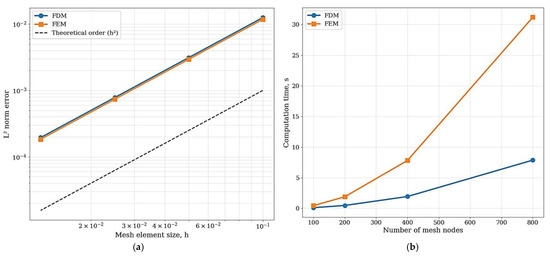
Figure 3.
Comparative analysis of FDM and FEM: (a) convergence of L2 error as a function of mesh size; (b) calculation time as a function of the number of grid nodes.
The data for the graphs is obtained by sequential calculation of the reference test problem on grids with different increments. The L2 error values are calculated as the norm of the difference between the numerical solution and the reference solution obtained on the maximum condensed grid (FEM with 4000 elements; FDM with 2000 nodes). The grid step h ranged from 0.0125 to 0.1. The CPU time was measured on a single computing system (Intel i7-12700H, one core) for each of the calculations performed to plot the graph in Figure 3a.
The calculation time (CPU time) of the graph in Figure 3b was measured for each of the calculations performed to plot the graph in Figure 3a. Measurements were carried out on the same computing system (Intel i7-12700H (Intel, Santa Clara, CA, USA), single core) to exclude the influence of background processes. The intervals are the number of nodes/elements ranged from 100 to 800. The corresponding calculation time for the FDM was between 0.12 and 7.88 s; for the FEM, it was between 0.45 and 31.2 s.
To exclude the influence of the complex geometry of the corrugation and stress concentrators, a smooth meridian shell of rotation was chosen as a test problem, for which there is an analytical or high-precision numerical solution. Such a problem provides a test case by which you can measure the approximation order of both methods.
- The FDM was tested on an axisymmetric formulation with a known analytical solution.
- The FEM was tested on the same geometry in the Ansys environment with sequential mesh thickening.
Remark on p-Convergence
In this study, the convergence analysis was limited to h-refinement (mesh densification) for both the finite difference and finite element methods. The p-convergence (increase in the polynomial order of the approximation functions) was not included because the FEM implementation employed in this work is based on standard quadratic shell elements (ę), whose interpolation order is fixed by formulation. These elements are widely used in engineering practice for thin shell problems and ensure second-order accuracy with respect to spatial discretization, which is sufficient for the reliability assessment tasks considered here.
Moreover, for the Kirchhoff–Love shell equations used in this study, higher-order p-refinement schemes would require special C1-continuous shape functions or the mixed interpolation of displacements and rotations, which substantially increases computational complexity without a significant gain in accuracy for the axisymmetric geometries analyzed. Nevertheless, the authors acknowledge the importance of p-convergence studies for evaluating the asymptotic behavior of FEM accuracy and plan to include this analysis in future work, especially for non-axisymmetric geometries and higher-order spline-based or NURBS elements.
5.3. Results of Convergence of the Finite Difference Method
Plots of the dependence of log Error L2 on log N, where N is the number of nodes in the arc coordinate, showed a linear trend with an angular coefficient close to −2, which corresponds to the second order of accuracy over space declared for the implicit symmetric scheme used (Figure 4). The error according to the norm L2 decreased from 10−3 at N = 100 to 10−6 at N = 800.
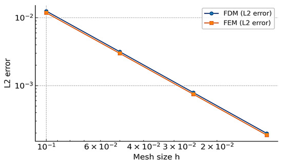
Figure 4.
Convergence on a benchmark problem: L2 error versus mesh size h (log-log).
A similar behavior was observed for the maximum stress error, while convergence was maintained even for problems with a local stress concentration in the corrugation region.
5.4. Results of Finite Element Convergence
With a sequential decrease in the characteristic size of the he element in the FEM model, the second order of approximation by the L2 displacement rate was observed. For shelled 8-node elements, the error according to the L2 norm decreased from 10−3 at he ≈ 3 mm to 10−6 at hz ≈ 0.5 mm.
Stress error control showed a slightly slower decrease, which is explained by their dependence on the first derivatives of displacements and increased sensitivity to mesh quality in regions with a high curvature.
5.5. Mutual Verification of Methods
A comparison of the solutions obtained by FDM and FEM for the same geometry and loads (Table 1 and Table 2) showed a good match:

Table 1.
Stability comparison for the finite difference method and the finite element method.
Table 2.
Comparison of numerical errors and convergence rates for the finite difference method and finite element method.
- The difference in the L2 displacement norm did not exceed 1% at a comparable level of sampling.
- The difference in the maximum equivalent Mises voltage was within 2%.
- The critical pressure according to the Mises criterion, calculated by both methods, coincided within 1.5%.
This confirms the correctness of both the difference and finite element implementations, as well as the correctness of the transition from the original PDE formulation to the reduced axisymmetric model.
5.6. Conclusions Based on the Results of the Analysis
The convergence analysis showed that both numerical methods (FDM and FEM) achieve the declared second-order accuracy in space and give similar results with sufficiently fine sampling. The FDM is more computationally cost-effective with strict axisymmetry and regular geometry (Table 3), while FEM is versatile and allows you to take into account arbitrary shapes and boundary conditions. The data in Table 3 are obtained in the course of calculations for the reference problem. Memory consumption was measured as the peak use of RAM in the process of solving a system of equations. Calculation time was measured without taking into account the meshing and post-processing steps. Memory usage was measured by the operating system and the ANSYS profiler (for FEM) as the peak RAM usage during calculation.
Table 3.
Computational cost comparison for the finite difference method and the finite element method.
6. Numerical Experiments
Numerical experiments were carried out to evaluate the stress–strain state (SSS) and stability of corrugated bellows expansion joints in real design configurations, as well as to determine critical loads according to the Mises criterion. All calculations were performed both by the finite difference method in a reduced axisymmetric formulation and by the finite element method in a complete 3D representation of the axisymmetric model.
The numerical simulations presented in this section are based on the same underlying system of partial differential equations introduced in Section 2: the Kirchhoff–Love shell equations for the equilibrium of membrane forces and bending moments under internal pressure. The finite difference method (FDM) and the finite element method (FEM) provide two different discretizations of this PDE system.
For the finite difference approach, the axisymmetric reduction described in Section 2.6 was employed, resulting in a first-order system of ordinary differential equations in the meridional coordinate s:
where represents the displacement components, and the coefficient matrices G(s) and H(s) depend on geometry and material parameters. This system was discretized using the implicit symmetric second-order difference scheme (Crank–Nicolson type) described in Section 3, with a uniform grid of N = 800 to 2000 nodes and fixed boundary conditions corresponding to embedded or hinged edges. Convergence was monitored until the relative change in displacement between successive iterations was below 10−6.
For the finite element approach, the full two-dimensional variational form of the same PDE system (Section 4.1) was implemented in the ANSYS environment using quadratic 8-node shell elements, ensuring the C1 continuity of displacements and rotations. The weak formulation was discretized in the finite element space Vh ⊂ [H2(S)]2 with the global matrix equation KU = F. Meshes contained 500 to 2000 elements along the meridian, and refinement studies confirmed second-order spatial accuracy in the L2 norm.
Hence, all numerical results reported below (stress fields, equivalent von Mises stresses, and critical pressures) correspond to solutions of the same PDE system (Kirchoff–Love shell equations) obtained by two independent numerical approximations. This guarantees that the comparison between FDM and FEM reflects differences in discretization rather than in the governing equations.
6.1. Geometry and Material Parameters
For modeling, three variants of corrugation geometry were used, corresponding to different industrial series of expansion joints. The main parameters included the following:
- The average radius of the bellows R being from 15 to 117 mm;
- The corrugation radius of r = 3.25 mm;
- The corrugation height W ranging from 10 to 15.2 mm;
- The wall thickness of h = 0.5 mm.
The material was steel with Young’s modulus of E = 200 GPa and Poisson’s ratio of ν = 0.3. The tensile yield strength was σy = 215 MPa.
The geometry of the bellows meridian was set analytically according to the parameters of the corrugation and then approximated in the computational grid. The FEM model took into account the exact reproduction of the profile, including the spirals between the corrugations.
6.2. Determination of Critical Pressure According to the Mises Criterion
For each geometry option, SSS calculations were performed at an internal pressure p increasing in the range from 0.5 MPa to the values close to the expected yield strength. During the calculations, the equivalent Mises stress field was determined:
where σι are the principal stresses on the corresponding envelope surface.
The critical pressure was determined according to the condition For all three sets of parameters, values in the range from 1.85 MPa to 2.10 MPa were obtained, and the discrepancy between the FDM and FEM results did not exceed 2%.
6.3. Analysis of the Stability of a U-Shaped Bellows
The second series of experiments was devoted to the analysis of the stability of the U-shaped bellows. For this purpose, a linear analysis of the eigenforms of buckling was used (Section 2.9).
In FEM calculations, the first three eigenforms were determined, including the following:
- Global shape—deflection of the bellows axis as a whole;
- Local shape—bending of individual corrugations in their plane;
- Combined form—superposition of global and local bends.
Figure 5 shows examples of bellows for which adjacent equilibrium shapes have been calculated to be obtained. The finite element mesh for this stability analysis was refined to ensure accurate resolution of the buckling modes. The models presented in Figure 6 utilized a mesh with approximately 2000 quadratic elements along the meridian, corresponding to an element size of he ≈ 0.5 mm. This level of discretization was confirmed to provide converged results for the eigenvalues and eigenmodes.
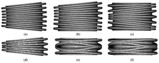
Figure 5.
Examples of bellows for which the calculation obtained adjacent forms of equilibrium: bellows consisting of seven (a–c) and four (d–f) corrugations, with articulated (a,d), mixed (b,e), and embedded (c,f) fasteners.
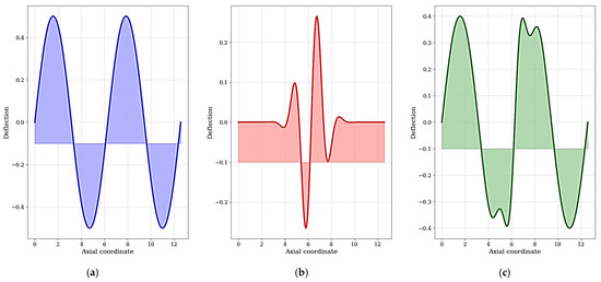
Figure 6.
Distribution of equivalent von Mises stress (in MPa) in a four-convolution bellows compensator under internal pressure p = 2.0 MPa, approaching the yield criterion limit: (a) Global Buckling Mode; (b) Local Buckling Mode; and (c) Combined Buckling Mode (the FEM results were obtained using a mesh with ~2000 elements along the meridian).
In order to visualize the load pattern and identify the most hazardous areas, a Mises equivalent stress distribution analysis was performed. Figure 6 shows the calculation results for a bellows with four corrugations at a pressure of 2.0 MPa, which is close to the calculated critical value for this configuration. The highest concentration, reaching 214.8 MPa, is observed on the inner surface at the root of the corrugation, which is explained by the action of the bending moment and the curvature of the surface. This value is almost close to the yield strength of the material (σy = 215 MPa), which confirms the adequacy of the calculation and indicates this zone as the probable place of the beginning of plastic deformation and subsequent failure. The obtained picture of stress distribution qualitatively agrees with the known literature data [5,8,12] and clearly demonstrates the need for careful control of the geometric parameters of these particular zones during design.
The results were obtained using the finite element method in Ansys. The stress concentration zones are clearly visible at the roots and crests of the convolutions, which are the most critical areas determining the compensator’s strength. The maximum stress value of 214.8 MPa is observed on the inner surface of the convolution root, which is consistent with the von Mises yield criterion for the given material (σy = 215 MPa).
As a result of the analysis of the eigenvalues and vectors of the stability problem, three fundamentally different forms of buckling loss were identified, as shown in Figure 6. The global shape (Figure 6a) is characterized by a smooth curvature of the bellows axis as a whole, similar to the longitudinal bending of a rod. This shape typically dominates over short bellows with a small number of corrugations. The local shape (Figure 6b) manifests itself as the bulging of individual corrugations inward or outward without significant displacement of the overall axis. This mechanism is predominant for thin-walled bellows with a large number of corrugations and can occur at pressures lower than required for global buckling. The combined shape (Figure 6) is an overlay of global and local bending. Identifying this shape is especially important, as it can lead to the most dangerous scenario of structural failure.
The ability of a finite element model to adequately reproduce all of these shapes, especially the local one, is a key advantage of full 3D staging over axisymmetric reduction, which can be blind to non-axisymmetric modes.
The critical pressure for the global buckling shape turned out to be consistent with the analytical calculation (the difference is up to 3% for long bellows). For short structures with a small number of corrugations, the local shape occurred at a lower pressure than that of the global one, which confirms the importance of taking into account local stability in the design.
6.4. Parametric Studies
Parametric studies not only determine critical loads but also assess the reliability margin of the structure when varying key parameters. The established dependencies between geometry and critical pressure make it possible to develop recommendations for the design of expansion joints with increased service life and resistance to various types of loading.
To assess the influence of geometric and physical parameters on critical pressures, a series of calculations were carried out with varying
- Wall thicknesses, h, from 0.3 to 0.7 mm;
- Numbers of corrugations, Ng, from 3 to 12;
- Moduli of elasticity, E, from 150 to 220 GPa.
The parameters of the distribution of the radial strain in the bellows at critical pressure as a result of the post-processing of the calculation of the first eigenbuckle shape in ANSYS are given in Figure 7.
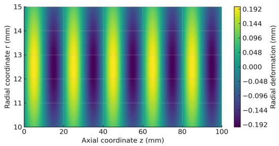
Figure 7.
Distribution of radial strain in bellows at critical pressure. The result of post-processing calculation of the first eigenbuckling shape in ANSYS (displacement field normalized to maximum value).
The distribution of equivalent Mises stresses in the bellows at the pressure corresponding to the onset of flow (P = 1.85 MPa) is shown in Figure 8. It can be seen that the stresses are recovered on the shell surfaces based on the calculated membrane forces and bending moments.
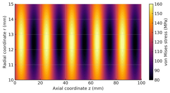
Figure 8.
Distribution of equivalent Mises stresses in the bellows at the pressure corresponding to the onset of flow (P = 1.85 MPa).
The results showed (Table 4) that the critical pressure for the yield criterion increases almost linearly with increasing thickness, while the critical pressure for stability has a nonlinear dependence: for small thicknesses, it increases faster than for large ones. Increasing the number of corrugations reduces the global critical pressure (the effect of “softening” the structure) but has almost no effect on local stability.
Table 4.
Critical pressure obtained by FEM and FDM for different geometric parameters.
Parametric analysis results showing the effect of key geometric parameters on the critical buckling pressure are visualized in Figure 9. The data for the graphs is obtained as a result of a series of calculations using the FDM. For Figure 9a, the wall thickness h ranged from 0.3 to 0.7 mm in 0.1 mm increments at a constant number of corrugations (Ng = 8). For Figure 9b, the number of Ng corrugations varied from 3 to 12. With a constant wall thickness (h = 0.5 mm) and a mean radius of R = 50 mm, it remained constant. The total length L of the bellows increased proportionally with the increase in Ng. Linear buckling analysis was performed for each set of parameters to determine Pcr.
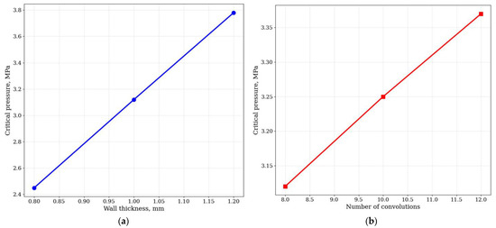
Figure 9.
Influence of geometric parameters on critical pressure: (a) the dependence on the wall thickness for a fixed number of corrugations; (b) the dependence on the number of corrugations for the fixed wall thickness.
As follows from Figure 9a, the critical pressure Pcr has an almost linear dependence on the wall thickness h. This is to be expected, since the flexural stiffness of the shell is proportional to h3 and the membrane stiffness is proportional to h, which together result in a strong dependence of the bearing capacity on the thickness.
Figure 9b illustrates the effect of the number of corrugations Ng. Pcr has been observed to increase with increasing Ng, but this increase is nonlinear and gradually saturated. This is due to the fact that an increase in the number of corrugations at a constant total length leads to a decrease in their height and radius of curvature, which, in turn, increases local rigidity and resistance to buckling. These graphs are the basis for optimizing bellows geometry during the preliminary design phase.
The data are derived from the parametric study described in Figure 9. For each set of parameters, the calculation was carried out using both the FEM (in ANSYS) and the FDM (in its own implementation) for subsequent comparison.
For all the studied configurations, the FDM and FEM qualitatively showed the same distributions of displacements and stresses (Table 5), as well as similar numerical values of critical pressures. The greatest discrepancy was observed in cases with local buckling, where the exact geometry of the profile has a significant impact on the result, and FEM can be considered in more detail.
Table 5.
The effect of the wall thickness and the convolution radius on the maximum von Mises stress.
Numerical experiments have confirmed that, in order to design bellows expansion joints, it is necessary to analyze both criteria (fluidity and stability) and take into account both global and local forms of buckling. The FDM is effective for quick sizing during the preliminary design phase, while FEM is preferred for the final design check before manufacturing.
7. Discussion
The performed studies made it possible to compare two different numerical approaches to solving the problem of the stress–strain state and stability of corrugated bellows expansion joints: the finite difference method and the finite element method, from the point of view of their accuracy, stability, and applicability. Since the original problem statement was formulated as a boundary value problem for a system of partial differential equations, special attention was paid to how each method discretizes and approximates these PDEs, as well as how boundary conditions and geometry features are implemented.
The results of the convergence analysis (Section 5) showed that both methods exhibited a second order of accuracy with respect to space, which corresponds to the chosen approximation schemes: the second-order central differences in the FDM and the quadratic basis functions in the FEM. This is consistent with theoretical expectations for these types of sampling [12,13]. At the same time, the FDM, due to the simplicity and regularity of the mesh, provides computational efficiency in solving axisymmetric problems in which geometry and load have rotational symmetry. As shown in Table 3, the gain in computational speed can reach four times with comparable accuracy for global parameters (critical pressure, maximum displacement). FEM, on the other hand, is more resource-intensive but retains accuracy in complex corrugation geometries, including transients and local stress concentrators, where reduction in TAC may be less accurate.
Numerical experiments (Section 6) revealed an important engineering feature: critical pressures determined by the Mises criterion and by the buckling condition can differ not only quantitatively but also in the nature of the limiting state. In a number of cases, the local form of the loss of stability occurs at lower pressures than that of the global one, which requires an extended formulation of the stability problem, taking into account the spatial structure of adjacent forms of the equilibrium. This is especially important for thin-walled bellows with a large number of corrugations, where traditional analytical methods based on smooth shell models can give non-conservative estimates. The results obtained are in good agreement with the data of other researchers who noted the tendency of corrugated structures to buckle locally [5,8].
From the point of view of formulating the problem as a PDE, the results demonstrate that the transition from a complete two-dimensional variational form on the surface to a one-dimensional reduced TAC system is possible without a significant loss of accuracy in the case of strict axisymmetry and the dominance of axisymmetric forms of buckling. However, when analyzing non-axisymmetric (e.g., lentil-shaped) forms of buckling or in the presence of significant geometric inhomogeneities, the reduced model loses its adequacy. Therefore, for problems where such effects are fundamental, it is preferable to use the full PDE model and discretize it using the finite element method.
In addition to the traditional discretization approaches discussed above, it is important to note the rapid development of advanced numerical paradigms that address some of the limitations inherent to conventional FEM and FDM strategies. One of the most significant advances in this area is Isogeometric Analysis (IgA), which provides an intrinsically higher degree of geometric fidelity by employing NURBS or spline-based basis functions identical to those used in CAD modeling. This enables the direct integration of engineering geometries into numerical analysis without the need for intermediate meshing or geometric simplification. When combined with the Boundary Element Method (BEM), IgA allows for the formulation of highly efficient and accurate computational frameworks capable of treating thin-walled structures and curved surfaces with minimal geometric approximation errors.
Recent works, such as [39], demonstrated that IgA–BEM formulations could outperform standard FEM approaches in problems involving the multi-axis curvatures and complex corrugation geometries typical of industrial bellows and compensators. These methods preserve the exactness of CAD-defined geometries, eliminate re-meshing steps, and reduce numerical dispersion in curvature-dominated regions. Incorporating these ideas into the future development of reliability-oriented bellows modeling may provide significant improvements in accuracy and computational robustness, particularly for non-axisymmetric configurations and adaptive geometric optimization.
The practical significance of the study lies in the fact that the developed numerical models can be used at different stages of design, forming a two-level analysis scheme:
- -
- Preliminary design phase (FDM) allows for quickly finding the optimal design parameters (wall thickness h, number of corrugations Ng, and corrugation radius r) by analyzing hundreds of options in acceptable time due to the efficiency of the FDM.
- -
- Final Validation Phase (FEM) provides detailed analysis of the selected configuration, taking into account all geometric nuances (exact corrugation shape, transition radii), complex boundary conditions, and non-axisymmetric buckling modes for a comprehensive reliability assessment. In addition, the proposed approaches and their verification create the basis for solving more complex PDE problems in shell mechanics, such as dynamic stability, oscillations under internal pressure, thermomechanical loading, and problems with nonlinear material properties.
The combined approach not only reduces material consumption but also ensures that there are no failures due to buckling or plastic deformation during a given service life.
Limitations of the study include the assumption of the linear elastic behavior of the material and the applicability of the Mises test to determine the onset of flow. Consideration of plasticity, fatigue damage, and fracture kinetics requires further development of the model. In addition, the reduced axisymmetric setting of FDM does not take into account the possible contact interactions between the bellows turns at full compression.
From a methodological point of view, the work confirms that the combination of a strict mathematical formulation of the problem in terms of PDE and the subsequent implementation of various discretizations (FDM and FEM) provides a reliable and universal tool for the analysis of complex engineering objects. This corresponds to the topic of numerical methods for PDE, as it demonstrates both the development of numerical algorithms for a specific PDE class (shell mechanics) and their verification and application in real engineering design. The practical significance of the study lies in the fact that the developed numerical models can be used at different stages of design:
- FDM for quick search for optimal design parameters with varying thicknesses, numbers of corrugations, and materials;
- FEM for the final design check, taking into account all geometric details and complex boundary conditions.
In addition, the proposed approaches are easily adaptable for solving other PDE problems in shell mechanics, such as dynamic stability, oscillations under internal pressure, thermomechanical loading, and problems with nonlinear material properties.
From a methodological point of view, the work confirms that the combination of a strict mathematical formulation of the problem in terms of PDE and the subsequent implementation of various discretizations (FDM and FEM) provides a reliable and universal tool for the analysis of complex engineering objects. This corresponds with the topic of the Special Issue of Numerical Methods for PDEs, as it demonstrates both the development of numerical algorithms for a specific PDE class and their application in real engineering design.
8. Conclusions
In this work, the problem of the stress–strain state and stability of corrugated bellows expansion joints was posed and solved, formulated as a boundary value problem for a system of partial differential equations that determine the behavior of a thin elastic shell of rotation within the framework of the Kirchhoff–Love theory. To solve the problem, two different approaches to the discretization of the original PDE model were applied: the finite difference method in a reduced axisymmetric formulation and the finite element method for the initial two-dimensional variational form. Based on the results of the study, the following main conclusions can be formulated:
- A complex mathematical model has been developed and implemented. The initial engineering problem is strictly formalized as a boundary value problem for the PDE system. The variational formulation of the problem makes it possible to apply the finite element method to the analysis of shells of complex geometry, and the reduction to the TAC system allows for using the effective finite difference method for axisymmetric cases.
- The FDM numerical scheme was created and verified. The proposed implicit symmetric second-order difference scheme demonstrated unconditional stability and second-order accuracy on test tasks with an analytical solution. The scheme is effective for parametric studies of axisymmetric configurations.
- A FEM model has been built and configured. The implementation of the finite element method in Ansys using shell elements with quadratic approximation provided the high accuracy modeling of complex corrugation geometry and various boundary conditions. The convergence analysis confirmed the second order of approximation.
- Mutual verification of the methods was carried out. A good correspondence between the results obtained by FDM and FEM was established. The discrepancies in the critical pressure determined by the Mises criterion did not exceed 2%, and in the buckling condition, it did not exceed 3% for global modes. This confirms the adequacy of both the reduced axisymmetric model (FDM) and the complete model (FEM).
- The key regularities of the influence of the parameters are revealed. Numerical experiments have shown that
- ○
- The critical pressure according to the yield criterion is linearly dependent on the wall thickness and practically does not depend on the number of corrugations.
- ○
- The critical buckling pressure (both global and local) has a nonlinear dependence on the wall thickness and decreases with an increase in the number of corrugations.
- ○
- For thin-walled bellows with a large number of corrugations, the dominant mechanism for bellows failure is local buckling, which occurs at pressures that are lower than those required for global buckling or reaching yield strength. Therefore, it is necessary to control reliability and increase it.
- A two-level design methodology is proposed. The expediency of the combined use of FDM at the stage of preliminary parametric analysis and optimization and FEM at the stage of final verification and the detailing of the selected design is substantiated. This allows you to significantly reduce the design time without compromising the reliability of the calculations.
The scientific novelty of the work lies in the development of an integrated approach to bellows modeling, combining strict PDE staging, an effective FDM algorithm for axisymmetric problems, and verification using FEM. The novelty consists of conducting a comparative analysis of two numerical methods, not only at the level of displacement and stress fields but also at the level of critical stability parameters, in identifying the conditions under which local stability becomes a limiting factor.
The practical value of the work is the creation of a universal method for calculating bellows expansion joints, which can be introduced into engineering practice to increase the reliability and validity of design solutions, as well as to reduce the material consumption and cost of products by optimizing the parameters.
Prospects for further research are associated with enhancing the developed models in the following areas:
- −
- Taking into account physical and geometric nonlinearity (plasticity, large displacements).
- −
- Analyzing cyclic strength and fatigue life.
- −
- Modeling dynamic processes and seismic impacts.
- −
- Studying thermomechanical loading.
- −
- Implementing algorithms for adaptive mesh thickening in stress concentration zones.
- −
- Optimizing corrugation geometry to increase load capacity and service life. The study clearly shows that the strict mathematical formulation of the problem and the use of two complementary sampling methods make it possible to effectively solve complex engineering problems of the mechanics of a deformable solid.
- −
- Calculating probabilistic reliability characteristics and forecasting residual life, taking into account material degradation and variable loading modes.
Author Contributions
Conceptualization, B.V.M. and N.V.M.; methodology, D.Y.T. and B.S.B.; software, S.N.S.; validation, D.Y.T. and B.S.B.; formal analysis, D.Y.T.; investigation, B.S.B.; resources, Y.Y.S. and D.Y.B.; data curation, S.N.S.; writing—original draft preparation, Y.Y.S. and D.Y.B.; writing—review and editing, B.V.M. and N.V.M.; visualization, S.N.S. All authors have read and agreed to the published version of the manuscript.
Funding
The research was conducted with financial support from the Ministry of Science and Higher Education of the Republic of Kazakhstan through the grant IRN AP22684027 Development and research of innovative technology and technique for increasing energy efficiency of technological machines with heavy rotor in starting modes.
Data Availability Statement
The original contributions presented in this study are included in the article. Further inquiries can be directed to the corresponding authors.
Conflicts of Interest
The authors declare no conflicts of interest.
References
- Zhou, M.; Mei, G. Transfer Learning-Based Coupling of Smoothed Finite Element Method and Physics-Informed Neural Network for Solving Elastoplastic Inverse Problems. Mathematics 2023, 11, 2529. [Google Scholar] [CrossRef]
- Zhou, M.; Qin, J.; Huo, Z.; Giampaolo, F.; Mei, G. epSFEM: A Julia-Based Software Package of Parallel Incremental Smoothed Finite Element Method (S-FEM) for Elastic-Plastic Problems. Mathematics 2022, 10, 2024. [Google Scholar] [CrossRef]
- Pryalukhin, A.F.; Klyuev, R.V.; Filina, O.A.; Konyukhov, V.Y.; Makarov, A.A. Improvement of Operational Reliability of Units and Elements of Dump Trucks Taking into Account the Least Reliable Elements of the System. World Electr. Veh. J. 2024, 15, 365. [Google Scholar] [CrossRef]
- Oh, M.-H.; Kim, S. Strategy to Improve Edge-Based Smoothed Finite Element Solutions Using Enriched 2D Solid Finite Elements. Appl. Sci. 2021, 11, 3476. [Google Scholar] [CrossRef]
- Pham, T.D.; Pham, Q.H.; Phan, V.D.; Nguyen, H.N.; Do, V.T. Free Vibration Analysis of Functionally Graded Shells Using an Edge-Based Smoothed Finite Element Method. Symmetry 2019, 11, 684. [Google Scholar] [CrossRef]
- Babyr, N.V.; Pogrebnoy, A.V.; Efremenkov, E.A.; Valuev, D.V.; Boltrushevich, A.E. Modelling of Reliability Indicators of a Mining Plant. Mathematics 2024, 12, 2842. [Google Scholar] [CrossRef]
- De Bellis, M.L.; Artioli, E. NURBS-Based Collocation Methods for the Structural Analysis of Shells of Revolution. Metals 2016, 6, 68. [Google Scholar] [CrossRef]
- Fernandes, S.C.F.; Cuartero, J.; Ferreira, A.J.M. Using Collocation with Radial Basis Functions in a Pseudospectral Framework for a New Layerwise Shallow Shell Theory. J. Compos. Sci. 2024, 8, 448. [Google Scholar] [CrossRef]
- Nussipali, R.; Konyukhov, V.Y.; Oparina, T.A.; Romanova, V.V.; Kononenko, R.V. Combined Power Generating Complex and Energy Storage System. Electricity 2024, 5, 931–946. [Google Scholar] [CrossRef]
- Bagapsh, A.; Soldatov, A. On the Solution of the Dirichlet Problem for Second-Order Elliptic Systems in the Unit Disk. Mathematics 2023, 11, 4360. [Google Scholar] [CrossRef]
- Zhou, R.; Jiang, J.; Qin, J.; Du, N.; Shi, H.; Wang, Y. Global Mechanical Response Sensing of Corrugated Compensators Based on Digital Twins. Appl. Sci. 2023, 13, 4048. [Google Scholar] [CrossRef]
- Daus, Y.V.; Konyukhov, V.Y.; Oparina, T.A.; Dubrovin, R.G. Simulation Modeling of Energy Efficiency of Electric Dump Truck Use Depending on the Operating Cycle. World Electr. Veh. J. 2025, 16, 217. [Google Scholar] [CrossRef]
- Li, X.; Bi, T.; Xu, H.; Shen, X. Study on Influencing Factors of Temperature Variation Displacement Compensation Behavior of Gas Insulated Switchgear Shell Bellows. Energies 2022, 15, 3954. [Google Scholar] [CrossRef]
- Demin, A.Y.; Pogrebnoy, A.V.; Efremenkov, E.A.; Valuev, D.V.; Boltrushevich, A.E. Modeling the Reliability of an Electric Car Battery While Changing Its Charging and Discharge Characteristics. Mathematics 2025, 13, 1832. [Google Scholar] [CrossRef]
- Iluk, A. Investigation of Mechanical Strains in Thermal Compensation Loop of Superconducting NbTi Cable during Bending and Cyclic Operation. Materials 2021, 14, 1097. [Google Scholar] [CrossRef] [PubMed]
- Wu, Y.; Tang, Y.; Qin, Z.; Chen, X.; Bai, H. Experimental and Numerical Research on a Pipe Element Passing through Bulkhead with Symmetrical Elastic Installation. Symmetry 2022, 14, 453. [Google Scholar] [CrossRef]
- Pogrebnoy, A.V.; Efremenkov, E.A.; Valuev, D.V.; Boltrushevich, A.E. Improving the Reliability of Current Collectors in Electric Vehicles. Mathematics 2025, 13, 2022. [Google Scholar] [CrossRef]
- Bitsadze, A.V. Boundary Value Problem for Second Order Elliptic Equations; North-Holland Publishing Company Amsterdam: Amsterdam, The Netherlands, 1968. [Google Scholar]
- Tovmasyan, N.E. General boundary value problem for second-order elliptic systems with constant coefficients. Differ. Uravn. 1966, 2, 163–171. (In Russian) [Google Scholar]
- Efremenkov, E.A.; Valuev, D.V.; Boltrushevich, A.E. Mathematical Modeling of Signals for Weight Control of Vehicles Using Seismic Sensors. Mathematics 2025, 13, 2083. [Google Scholar] [CrossRef]
- Saks, R.S. Boundary Value Problems for Elliptic Systems of Differential Equations; Izd-vo NGU: Novosibirsk, Russia, 1975. (In Russian) [Google Scholar]
- Douglis, A.A. A function-theoretic approach to elliptic systems of equations in two variables. Comm. Pure Appl. Math. 1953, 6, 259–289. [Google Scholar] [CrossRef]
- Matienko, O.I.; Kukartsev, V.V.; Antamoshkin, O.A.; Karlina, Y.I. Mathematical Model for the Study of Energy Storage Cycling in Electric Rail Transport. World Electr. Veh. J. 2025, 16, 357. [Google Scholar] [CrossRef]
- Hile, G.N. Elliptic systems in the plane with order terms and coustant coefficients. Comm. Part Diff. Equ. 1978, 3, 949–977. [Google Scholar] [CrossRef]
- Vekua, I.N. Generalized Analytic Functions; Pergamon: Oxford, UK, 1962. [Google Scholar]
- Khekert, E.V.; Antamoshkin, O.A.; Remezov, I.S. Battery Charging Simulation of a Passenger Electric Vehicle from a Traction Voltage Inverter with an Integrated Charger. World Electr. Veh. J. 2025, 16, 391. [Google Scholar] [CrossRef]
- Bers, L. Theory of Pseudo-Analytic Functions; Lecture Notes; New York University: New York, NY, USA, 1953. [Google Scholar]
- Boyarskii, B.V. Theory of generalized analytic vector. Ann. Pol. Math. 1966, 17, 281–320. [Google Scholar]
- Malozyomov, B.V.; Khekert, E.V.; Martyushev, N.V.; Konyukhov, V.Y.; Chetverikova, V.V.; Golik, V.I.; Tynchenko, V.S. Improving the Reliability of the Protection of Electric Transport Networks. World Electr. Veh. J. 2025, 16, 477. [Google Scholar] [CrossRef]
- Gilbert, R.P. Constructive Methods for Elliptic Equations; Lecture Notes in Mathematics; Springer: Berlin/Heidelberg, Germany, 1974; Volume 365. [Google Scholar] [CrossRef]
- Gilbert, R.P.; Hile, G.N. Generalized hypcrcomplex function theory. Trans. Am. Math. Soc. 1974, 195, 1–29. [Google Scholar] [CrossRef]
- Volpert, I. On the index and normal solvability for elliptic systems of differential equations on the plane. Tr. Mosk. Mat. Obs. 1961, 10, 41–87. (In Russian) [Google Scholar]
- Sirazhudinov, M.M. Boundary value problems for general elliptic systems on a plane. Math. USSR Izv. 1997, 61, 137–176. (In Russian) [Google Scholar] [CrossRef]
- Hua, L.K.; Lin, W.; Wu, C.Q. On the uniqueness of the solution of the Dirichlet problem of the elliptic system of differential equations. Acta Math. Sin. 1965, 15, 174–187. [Google Scholar]
- Hua, L.K.; Lin, W.; Wu, C.-Q. Second-Order Systems of Partial Differential Equations in the Plane; Pitman Advanced Publishing Program: Boston, MA, USA; London, UK; Melbourne, Australia, 1985. [Google Scholar]
- Bagapsh, A.O.; Fedorovskiy, K.Y. On energy functionals for second-order elliptic systems with constant coefficients. Ufa Math. J. 2022, 14, 14–25. (In Russian) [Google Scholar] [CrossRef]
- Landau, L.D.; Lifshitz, E.M. Theory of Elasticity; Butterworth-Heinemann: Oxford, UK, 1986. [Google Scholar]
- Zaitsev, A.B. On univalence of solutions of second-order elliptic equations in the unit disk on the plane. J. Math. Sci. 2015, 215, 601–607. [Google Scholar] [CrossRef]
- Desiderio, L.; D’Inverno, G.A.; Sampoli, M.L.; Sestini, A. Hierarchical matrices for 3D Helmholtz problems in the multi-patch IgA-BEM setting. Eng. Comput. 2025, 41, 2021–2042. [Google Scholar] [CrossRef]


Disclaimer/Publisher’s Note: The statements, opinions and data contained in all publications are solely those of the individual author(s) and contributor(s) and not of MDPI and/or the editor(s). MDPI and/or the editor(s) disclaim responsibility for any injury to people or property resulting from any ideas, methods, instructions or products referred to in the content. |
© 2025 by the authors. Licensee MDPI, Basel, Switzerland. This article is an open access article distributed under the terms and conditions of the Creative Commons Attribution (CC BY) license (https://creativecommons.org/licenses/by/4.0/).