Abstract
Self-oscillating systems convert steady external stimuli into sustained motion, enabling diverse applications in robotics, energy absorption, optics, and logic. Inspired by the adhesion–detachment behavior of climbing plants, we propose a novel light-powered self-adhesion oscillator comprising an elastic strip–substrate structure and a weight suspended by a photo-responsive liquid crystal elastomer fiber. By integrating a nonlinear beam deformation model with Dugdale’s cohesive model, we develop a nonlinear dynamic framework to describe the self-adhesion behavior of the elastic strip. Quasi-static analysis reveals two distinct operating modes: a static mode and a self-adhesion mode. Under constant light exposure, the liquid crystal elastomer fiber undergoes light-induced contraction, increasing peeling force and triggering a sudden transition from adhesion-on to adhesion-off. Upon entering the adhesion-off state, the fiber recovers its contraction, leading to a sharp return to the adhesion-on state. This cycle sustains a four-stage oscillation: gradual peeling, abrupt adhesion-off, gradual adhering, and abrupt adhesion-on. Furthermore, we identify the critical conditions for initiating self-adhesion and demonstrate effective control over the oscillation period. The system exhibits key advantages including amplitude controllable oscillation, widely tunable frequency, well-defined motion trajectories, and structural simplicity. These characteristics suggest promising potential for applications in self-healing adhesion systems, rescue devices, military engineering, and beyond.
Keywords:
interface cohesive; self-oscillation; liquid crystal elastomers; optically responsive; adhesion–detachment mechanism MSC:
74G05; 74-10; 74F05; 93B52
1. Introduction
Self-sustained oscillations represent a class of persistent, rhythmic dynamics that arise in active matter or engineered structures, powered by a steady external energy source [1,2,3]. These systems operate without requiring alternating stimuli or discrete triggering signals, depending primarily on continuous power input and built-in regulatory feedback loops [3,4]. Such autonomous operation exhibits inherent stability and often structural simplicity, with the oscillation frequency largely governed by the system’s intrinsic parameters rather than the characteristics of the external energy supply [2,3]. Owing to these attributes, self-sustained oscillators are highly promising for a range of technologies including autonomous robotics [5,6,7,8,9], energy dissipators [10,11,12,13], matter transport platforms [14], photonic devices [15], and logic gate implementations [16,17].
Considerable research has been directed toward achieving self-sustained oscillations using a range of stimuli-responsive materials, such as thermally sensitive polymers [5,18], hydrogels [19,20], and liquid crystal elastomers (LCEs) [21,22,23,24,25,26,27], among others. By building upon these materials, a wide spectrum of self-oscillatory behaviors has been successfully realized. These include bending [28,29,30], rolling [31], vibrating [32,33,34,35], twisting [36,37], expansion and contraction [38,39,40], swinging [41,42,43,44], rocking [45], wobbling [46], tapping [47], toppling [48], ejecting [49], striking [50], Huygens-type synchronization [51], and even hybrid multi-mode motions [52,53,54,55]. A fundamental aspect of these rhythmic behaviors is that they often originate from intrinsic nonlinear feedback mechanisms within the material systems. Representative examples include self-shadowing [15,56,57], which enables periodic modulation of stimulus exposure; non-uniform environmental fields with spatial gradients in stimulus intensity [58,59,60,61]; and self-regulated field effects involving dynamically controlled energy release cycles or pathways [62,63]. These designed nonlinearities effectively transform a constant external energy supply into continuous periodic motion.
From the perspective of dynamic behavioral characteristics, self-sustained motion exhibits three primary patterns: bifurcation-driven motion around a unique static equilibrium point [29,32], snap-through motion involving transitions between multiple steady states [16,17], and steady-state motion with zero-energy modes [63]. Among these, bistable systems, which utilize their natural bistable characteristics to induce non-equilibrium dynamics, have gained considerable interest in the study of self-sustained oscillations [16,17,64,65,66,67]. These systems feature two stable states separated by an energy barrier, which must be overcome for a transition to occur. During the transition, the system may momentarily exhibit instability before settling into the new stable state. Leveraging bistable systems for self-sustained motion offers advantages, including enhanced amplitude regulation due to clearly defined stable states, well-characterized motion profiles governed by transition pathways, and the ability to maintain the system in either an ‘on’ or ‘off’ state. Current research explores various bistable structures for oscillation generation, such as elastic membranes undergoing snap-through between concave and convex states under constant pressure [16,17], pH-responsive hydrogels that oscillate between swollen-buckled and complementary configurations [66], bilayer shallow shells shifting between stable equilibrium states under illumination [67], and bistable systems performing complex sequential logic operations through controlled transitions [17].
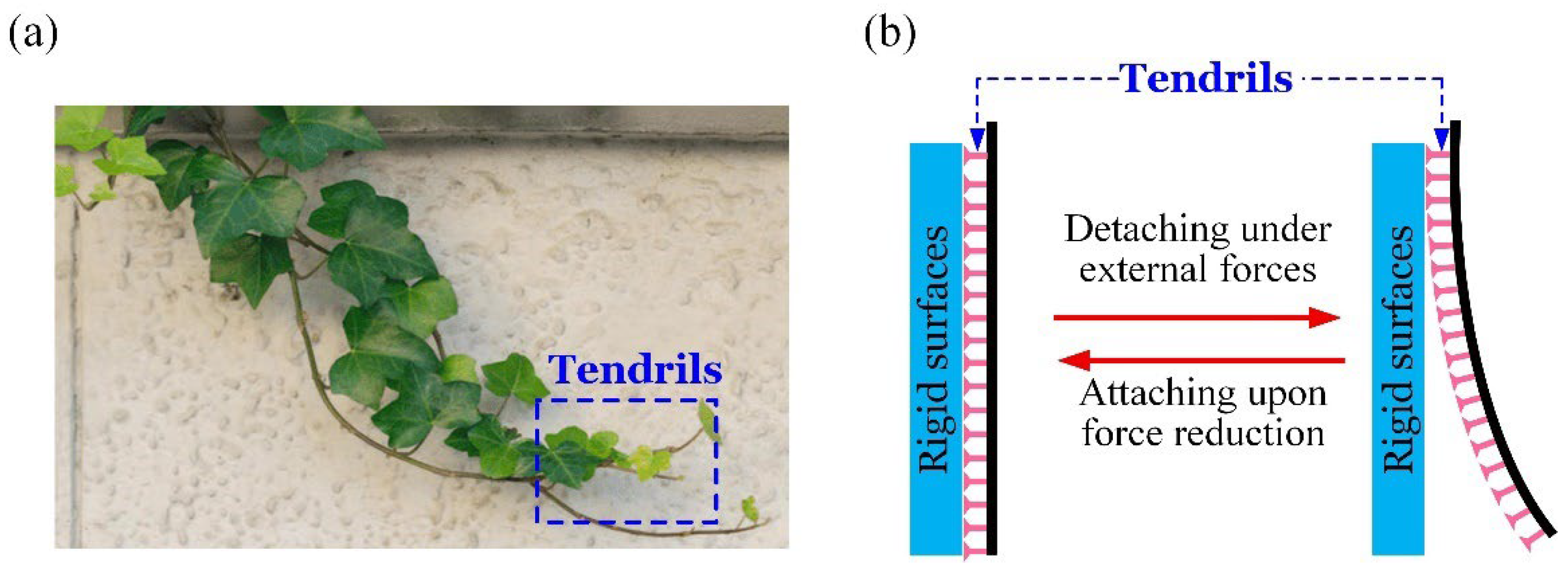
Indeed, building a self-sustaining system with bistable properties is a complex task, as there are few structural configurations capable of displaying distinct energy barriers, and inducing transitions between these states proves difficult. To address this, nature provides ingenious models where biological systems accomplish effective state transitions through advanced structural or mechanical processes. One such example is climbing plants, such as Boston ivy and common ivy, which use specialized tendrils to attach themselves to rigid surfaces. Under external forces, such as wind, these tendrils may temporarily detach, but upon force reduction, they may reattach [68,69], as illustrated in Figure 1. Inspired by the dynamic adhesion-detachment behavior found in nature, we propose a novel light-powered self-adhesion oscillator consisting of an elastic strip–substrate structure and a weight suspended by a photo-responsive LCE fiber. By introducing a baffle, the peeling strip is prevented from excessive separation, creating two energy barriers between the adhesion-on and adhesion-off states. Under constant light exposure, the contraction of the LCE fiber increases the peeling force that acts on the strip, prompting a rapid transition from the adhesion-on state to the adhesion-off state. In the adhesion-off state, the fiber’s length recovery reduces the peeling force, leading to a swift return to the adhesion-on state. The unexpected self-adhesion cycles, caused by imperfections in the strip detached from the substrate, are reminiscent of the behavior observed in imperfect electronic circuits [70]. This dynamic behavior is also akin to stick-slip systems with hysteresis and magnetic oscillators [71,72]. Additionally, when subjected to external disturbances or considering the dynamics of weight, this self-adhesion oscillator may exhibit chaotic oscillatory behavior or undergo dynamic bifurcations [73,74,75,76].
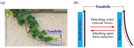
Figure 1.
Switchable adhesion between tendrils and rigid surfaces. (a) Climbing plants with tendrils. (b) Switchable adhesion.
Through quasi-static analysis, we establish a comprehensive dynamic framework to describe the self-adhesion behavior of the elastic strip, and identify two operating modes: static and self-adhesion. This alternating cycle facilitates the self-sustaining oscillation of the system. Thanks to the advantages of mathematical modeling [77], the critical conditions for initiating self-adhesion and controlling the strategy of the oscillation period are explicitly derived. The system offers advantages such as well-defined reversible motion trajectories, broad tunability of the oscillation period, and structural simplicity. We anticipate that this study will encourage the creation of innovative self-sustaining motion patterns and provide foundational insights for applications in self-healing adhesives, search and rescue operations, and military technologies.
The organization of this paper is outlined as follows. Section 2 develops a theoretical model of the light-powered self-adhesion oscillator, combining a nonlinear beam deformation formulation with Dugdale’s cohesive zone model. Section 3 analyzes the two motion modes exhibited by the oscillator under steady illumination and elucidates the detailed mechanics of the self-adhesion process. Section 4 establishes the critical conditions required to initiate self-sustained adhesion. Section 5 discusses the influence of key system parameters on the oscillation cycle. Finally, Section 6 concludes the paper with a summary of findings.
2. Theoretical Framework and Governing Equations
This section establishes a theoretical model for a self-adhesion oscillator under constant illumination, including the photo-induced self-adhesion oscillator dynamics, elastic thin-strip peeling behavior, transitions between the adhesion-on and adhesion-off states, and nondimensionalization.
2.1. Model of Photo-Induced Self-Adhesion Oscillator
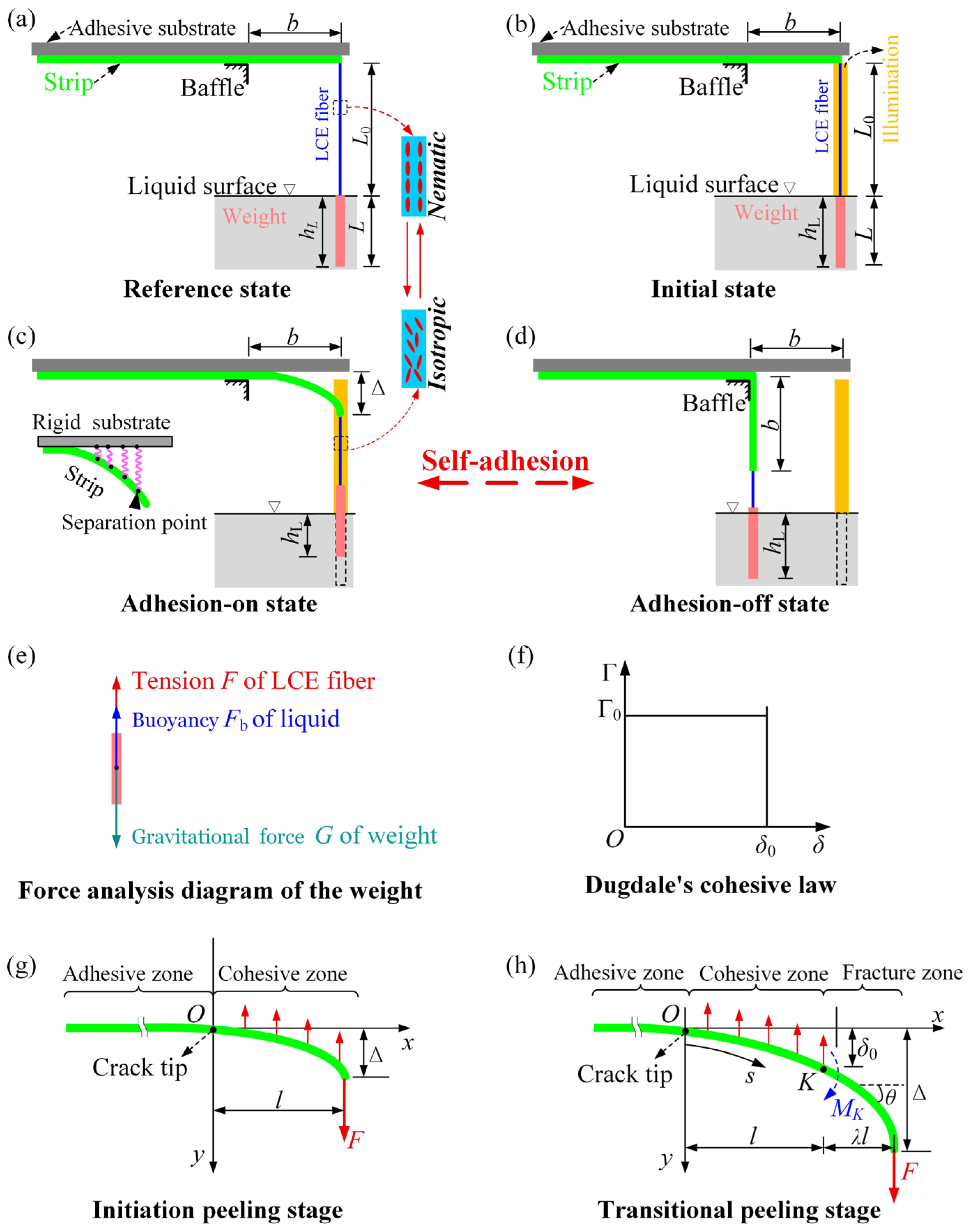
The structural model of the light-powered self-adhesion oscillator comprises a long strip with thickness , adhered to a rigid substrate at its top surface, as shown in Figure 2a. A baffle is positioned below the strip at distance from its right end. A liquid reservoir is positioned beneath the strip, where the liquid surface is at a distance of from the strip. A suspended weight with length is attached to the strip’s right end via a nematic LCE fiber. In the reference state, the stress-free LCE fiber has initial length and uniform alignment of LC mesogens along its axis. For the case where the mass density of the weight exceeds that of the liquid, the weight is submerged in the underlying liquid. It is well-known that under light exposure, photothermal heating progressively increases the temperature of the nematic LCE fiber, leading to a nematic-to-isotropic phase transition, which induces axial contraction. This contraction is fully reversible upon cooling [23,24,25,78].
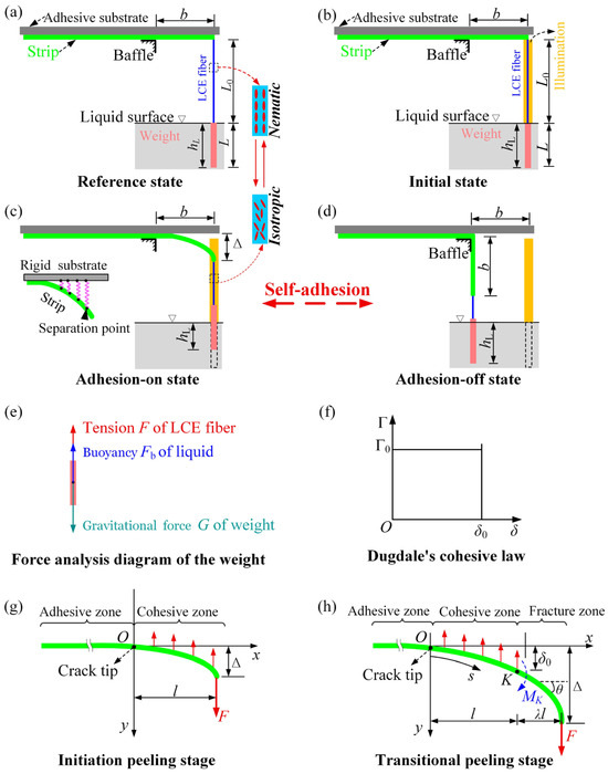
Figure 2.
Schematic of the light-powered self-adhesion oscillator: (a) reference state; (b) initial state; (c) adhesion-on state; (d) adhesion-off state; (e) force analysis diagram of the weight; (f) Dugdale’s cohesive law; (g) initial peeling stage; (h) transition peeling stage. Under steady illumination, the peeling strip via abrupt transition displays periodic self-adhesion behavior.
Upon release of the weight, the gravitational force induces the tension of LCE fiber, generating a peeling force on the elastic strip. This peeling force is counteracted by the adhesive force of the substrate, thereby maintaining the strip in an almost fully bonded adhesion-on state. In the initial state, a steady light illuminates a narrow zone near the central plane of the LCE fiber, leaving the rest in darkness, as shown in Figure 2b. Since the LCE fiber in the illuminated zone, contraction along its length occurs. As a result, the weight gradually rises above the liquid surface, leading to a corresponding decrease in buoyancy, thereby increasing the tension of the LCE fiber and the peeling force on the strip. This initiates a gradual separation at the strip-substrate interface, marking the transition toward an adhesion-off state, as shown in Figure 2c. With further contraction of the LCE fiber and an increase in the peeling force on the strip, sudden detachment from the substrate may occur. However, peeling ceases at the baffle position (Figure 2d), marking the adhesion-off state. In this state, the weight submerges deeper, abruptly increasing buoyancy while the LCE fiber moves into the dark zone. Subsequent relaxation of the LCE fiber in darkness further increases submersion depth and buoyancy. This elevated buoyancy reduces both LCE fiber’s tension and peeling force, enabling strip reattachment to the substrate due to adhesion—thus re-establishing the adhesion-on state. Accordingly, the LCE fiber moves back to the illuminated zone. Thus, periodic oscillations of the LCE fiber between illumination zones and darkness drive cyclical transitions of the strip between adhesion-on and adhesion-off states, as shown in Figure 2c,d.
During the self-adhesive oscillation of the strip, its right end experiences peeling force equivalent to the tension of the LCE fiber. For simplicity, the gravity of the LCE fiber is neglected, allowing to be determined through force analysis on the weight as depicted in Figure 2e. The weight is subjected to three forces: the tension of LCE fiber, the gravitational force of weight, and the buoyant force from the liquid. Using a quasi-static analysis method, the peeling force is determined by the following equation:
where gravitational force ( is the mass per unit length of weight; is gravitational acceleration), and buoyant force ( denotes the buoyancy coefficient, and is the submerged length of the weight in liquid). Geometrical analysis yields the weight’s submerged length through the expression:
in which represents the vertical peeling displacement of the strip, and is the contraction length of the LCE fiber. It is worth noting that for LCE fiber subjected to both light exposure and tensile loading from a weight, the elastic deformation caused by the tensile force results in a smaller actual shrinkage compared to the deformation caused by photothermal shrinkage alone. However, this discrepancy can be compensated by increasing the actual photothermal shrinkage. Furthermore, if the elastic stiffness of the LCE fiber is sufficiently high, the elastic deformation becomes negligible. For simplicity, this work considers only the photothermal shrinkage of the LCE fiber. Thus, the contraction length of the LCE fiber is calculated as
where denotes the photothermal contraction in the LCE fiber.
Combining Equations (2) and (3), Equation (1) can be rewritten as
It is worth noting that the weight’s submerged length must satisfy the condition . When , the peeling force is equal to the gravitational force of the weight, i.e., . When , the peeling force is determined by the following expression:
Clearly, the peeling force must satisfy .
As observed from Equation (4), during the adhesion-on state between the strip and substrate, continuous illumination elevates the photothermal contraction of LCE fiber, gradually increasing peeling force . When reaches the critical detachment force of adhesion-on (), the system suddenly transitions from adhesion-on to adhesion-off. Conversely, in the adhesion-off state, when peeling force decreases to the critical attachment force of adhesion-off (), the system suddenly reverts to adhesion-on. Consequently, and govern the adhesive state transitions between the strip and substrate, which will be calculated subsequently.
2.2. Critical Conditions of Adhesion-On and Adhesion-Off
Progressive interface separation occurs with increasing detachment force. Typically, peeling of an elastic strip from a rigid substrate involves three stages: Initial peeling stage where force increases with displacement until reaching maximum, Transitional peeling stage where force decreases with further displacement [79,80,81,82], and Steady-state peeling stage governed by Kendall’s model where force remains constant [80,81,82,83]. We define the maximum detachment force at the initial-to-transition stage transition as the critical detachment force . Conversely during steady-state peeling, reduced detachment force may initiate rapid strip reattachment; thus, we define this steady-state detachment force as the critical attachment force .
To compute the critical detachment force, schematics of the initial and transitional peeling stages are presented in Figure 2g,h, respectively. The light-induced contraction and recovery rates of LCE materials are closely related to their thickness. Specifically, the photothermal relaxation process involves a gradual decrease in temperature, resulting in a slow recovery of LCE deformation. Consequently, the strip undergoes a progressive detachment from the initial adhesion-on state to the critical adhesion-on state. Once the detachment force reaches the critical detachment force in the adhesion-on state, rapid detachment of the strip may occur. Similarly, the strip undergoes a progressive reattachment from the initial adhesion-off state to the critical adhesion-off state. Once the detachment force reaches the critical attachment force in the adhesion-off state, rapid reattachment of the strip may occur. Therefore, a quasi-static detachment force is applied vertically at the right end of the strip in both the adhesion-on and adhesion-off states. During peeling, the strip-substrate interface gradually separates ahead of the peeling front, forming a cohesive zone described by a constant-stress Dugdale cohesive law [84,85] (Figure 2f). Interfacial failure is determined by normal interface separation. According to this cohesive law, interfacial traction and interfacial separation relate as follows:
where represents the interfacial strength and denotes the critical interfacial separation, at which the interface will completely fail. For constant-stress cohesive law, interface toughness integrates as:
During the transitional peeling stage, the strip comprises three distinct regions [82,83] (Figure 2h): (1) Left of the interface crack tip exhibiting perfect substrate adhesion; (2) An adjacent cohesive zone of length at the interface obeying constant-stress cohesive law with uniformly distributed stress; and (3) A remaining interface failure region of length devoid of traction. For the peeling strip, a rectangular coordinate system describes deformation, with origin positioned at the interface crack tip and following crack propagation. With a small deformation assumption for the cohesive zone [86], the governing equation of an infinitesimal beam-element is approximately represented as:
variable denotes strip’s cohesive zone deflection (i.e., interfacial separation), where is for the strip, and equivalent elastic modulus with and being Young’s modulus and Poisson’s ratio, respectively.
The bending moment in Equation (8) can be expressed as
For the strip adhered to a rigid substrate (as shown in Figure 2g,h), the strip-substrate interface experiences point contact at the crack tip [82,87], resulting in the following boundary conditions:
Therefore, the cohesive zone length can be obtained
and the cohesive zone deflection can be obtained as follows:
From Equation (11), it is evident that the cohesive zone length depends on both and . Consider the following conditions,
yields to
Subsequently, the detachment force can be determined using Equation (11) as follows:
From Equation (15), Figure 2g,h, it can be observed that during the initial peeling stage, where and , the peeling displacement increases monotonically as the detachment force rises. Once the detachment force reaches its peak, the transitional peeling stage begins, characterized by and , where the peeling displacement continues to increase and the length of the interfacial failure zone increases [79,80,81]. Meanwhile, the bending moment () at the cohesive-fracture interface increases with the length of the failure zone (as shown in Figure 2h), until the peeling angle reaches 90° [80,81]. Eventually, the peeling behavior enters a steady state [81,82]. During the steady-state peeling stage, the peeling displacement increases, while both the length and the elastic bending moment remain constant [80]. Therefore, detachment force maximization occurs at and , and critical detachment force can be derived from Equation (15) as:
By substituting Equation (7), Equation (16) can be rewritten as
and the maximum value of the cohesive zone length can be obtained from Equation (14) as:
In the adhesion-on state, as illumination continuously heats the LCE, detachment force gradually increases until reaching the critical detachment force . At this transition point where , the photothermal contraction defines the adhesion-on threshold . When , the strip detaches abruptly from the substrate, causing the system to switch from the adhesion-on to adhesion-off state while the LCE fiber translocates to the dark zone. Notably, this occurs when the strip’s vertical peeling displacement satisfies . Solving Equations (5) and (17) yields as:
It is worth mentioning that several typical constitutive relations of the cohesive zone have been proposed [79]. Generally, deriving explicit solutions for the maximum detachment force and the maximum cohesive zone length during the initial-to-transition stage is difficult. However, analytical solutions for and can been obtained for the special cases of Dugdale’s constant-stress model and the type I triangular traction-separation law. Considering that the curve shape of the traction-separation relation has a relatively minor impact on interface characterization compared with strength and toughness parameters [79,80], this study employs the Dugdale’s cohesive law. For other cohesive zone models (e.g., triangular or exponential forms), the maximum detachment force shows a slight decrease [81], but it does not physically change the transition from the adhesion-on state to the adhesion-off state.
For this 90° detachment force in adhesion-off state, variables , and will remain constant [77,80]. According to the classical Kendall’s model [78,82], steady-state detachment force equals interface toughness. Therefore, the critical attachment force can be rewritten as:
In the adhesion-off state, the detachment force persistent reduces due to the LCE cooling in darkness. At this transition point where , the corresponding photothermal contraction defines the adhesion-off threshold . When , the system switches from the adhesion-off state to adhesion-on state, while the LCE fiber moves into the illuminated zone and becomes re-exposed to light. Notably, the vertical peeling displacement at this stage results from the combined action of detachment force and the baffle constraint. For analytical simplicity, is fixed at distance between the baffle and strip’s right end in the reference state (). Solving Equations (5) and (17) determines as follows:
2.3. Duration of the Self-Adhesion
The self-adhesion process of the strip is governed by changes in photothermal contraction. This section focuses on the dynamic model of photothermal contraction in the LCE fiber. To simplify, it is assumed that the photothermal contraction is linearly dependent on the temperature difference in the LCE fiber, i.e.,
where is the photothermal contraction coefficient of the photothermal-responsive LCE material.
Given the fiber’s negligible radius, the temperature across the LCE fiber can be considered uniform. Through photothermal conversion, the fiber transforms light illumination into thermal energy at rate (light intensity). Concurrent heat exchange with the environment exhibits heat flux linearly proportional to . Under illumination, is governed by:
where denotes heat transfer coefficient and specific heat capacity. Crucially, represents the maximum attainable temperature difference, while characterizes the photothermal fiber-environment heat exchange timescale. Larger values prolong attainment of . Thus, Equation (23) is rewritten as follows:
The temperature difference can be obtained by solving Equation (24) as:
where is the temperature difference at the initial moment of exposed to light.
In this work, the LCE fiber alternates between illumination zone and darkness zone. In Case I, where the LCE fiber transitions from the darkness zone to the illumination zone with a transient temperature difference , Equation (25) can be simplified to:
where is the duration of exposed to light.
Considering that the instantaneous photothermal contraction for the activation adhesion-on satisfies , the transient temperature difference can be derived from Equation (21) and expressed as:
The adhesion-off phase is activated when . Following this, the transient temperature difference for the abrupt transition from adhesion-on to adhesion-off can be derived from Equation (19) and expressed as:
Therefore, by combining Equations (27) and (28) and setting into Equation (26), the solution of is the total duration for adhesion-on state. Thus, can be obtained as follows:
In Case II, where the LCE fiber transitions from the illumination zone to darkness zone. with a transient temperature difference . Setting , Equation (26) can be simplified to:
where is the duration of darkness. The adhesion-on phase is activated when . Therefore, by setting Equation (27) that into Equation (30), the solution of is the total duration for adhesion-off state. Thus, can be obtained as follows:
It is worth mentioning that Equations (25) and (26), respectively, govern the temperature difference evolution of the LCE fiber in the adhesion-on and adhesion-off states. These two distinct evolution behaviors are the underlying cause of the hysteresis effect in the self-adhesion system. When exposed to external disturbances or influenced by the dynamics of weight, this self-adhesion oscillator could display chaotic oscillations or experience dynamic bifurcations.
2.4. Nondimensionalization
For analytical simplification, the following dimensionless quantities are defined: , , , , , , , , , , , , , , , and . During the self-adhesion, the dimensionless buoyant force in Equation (5) is re-expressed as
and the dimensionless weight’s submerged length is
The dimensionless vertical peeling displacement under the adhesion-on state in Equation (15) satisfies:
under the adhesion-off state is
Crucially, the dimensionless submerged length must satisfy , while the dimensionless detachment force is constrained by .
From Equations (17) and (20), the dimensionless critical detachment force and the critical attachment force can be given as
and
From Equations (19) and (21), the critical photothermal contraction of adhesion-on and adhesion-off are expressed as:
and
From Equations (29) and (31), the dimensionless durations and are expressed as:
and
The photothermal contraction in Equation (22) is rewritten as:
From Equation (24), the dimensionless photothermal temperature difference for adhesion-on state evolves as follows:
Notably, the maximum attainable temperature difference is zero for the adhesion-off state. Therefore, the evolution of for the adhesion-off state is given by:
Under the small deformation assumption for the cohesive zone, the dynamics of the self-adhesion oscillator, which operates in both adhesion-on and adhesion-off states, are described explicitly by Equations (32)–(44). For a specified temperature difference at a given time , the current photothermal contraction of the LCE fiber can be calculated using Equation (41), and the state of the strip is determined using Equations (38) and (39). Subsequently, the temperature difference at a particular time can be determined from Equations (43) and (44). Therefore, the dynamics of the self-adhesion oscillator can be derived through iterative computations using the provided parameters: , , , , , , and .
2.5. Verification by Numerical Solutions
In this section, the accurate peeling model solution is provided to validate the analytical solutions based on the small deformation assumption. The operation of the self-adhesion oscillator results from multiphysics coupling, which includes the adhesion between the strip and substrate, the photothermal contraction and recovery of LCE fiber, the buoyancy of the weight in liquids, and the boundary effects of the baffle. Among these, the peeling process of the strip under the influence of photothermal contraction in LCE fibers is crucial to the study. Therefore, we have incorporated a numerical solution based on an accurate peeling model to examine the effect of photothermal contraction on strip peeling and compared it with the original analytical solution based on the small deformation assumption. To describe the deformation of the strip, a curvilinear coordinate system is introduced, with its origin located at the interface crack tip and following the direction of crack propagation, as illustrated in Figure 2h. The relationship between the rectangular coordinate system and the curvilinear coordinate system can be expressed as follows:
Defining and inserting Equation (45), Equation (47) can be rewritten as
From Equation (9), the dimensionless elastic bending moment in cohesive zone can be expressed as
The end-separation at the strip terminus and the y-axis coordinate can be obtained by solving the following equations:
Let , the cohesive zone deflection described in Equation (12), based on the small deformation assumption, can be rewritten as
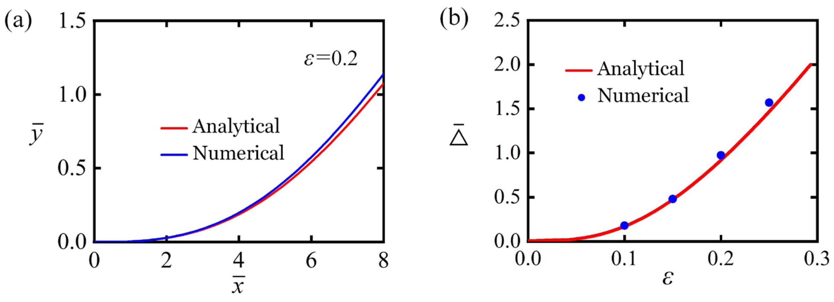
As shown in Equation (32), the detachment force of the strip depends on both the end-separation and photothermal contraction . Meanwhile, in Equation (50) is determined by the solutions of the differential Equations (45)–(47), which involve the unknown parameters and . Deriving analytical solutions for such a system proves challenging. By incorporating the boundary conditions from Equation (10), numerical methods are employed to derive the results. With the given parameters , , , , and , both analytical and numerical solutions are visualized in Figure 3. Importantly, the analytical solution for the cohesive zone’s deflection can be obtained from Equation (52), and the end-separation is derived by solving Equations (34) and (36) simultaneously. As shown in Figure 3a, under the adhesion-on state, part of the strip shows detachment deflection. As the photothermal contraction increases gradually, the strip progressively detaches from the substrate, and the end-separation enlarges, as demonstrated in Figure 3b. A comparison between the analytical solutions (derived under the small deformation hypothesis) and the numerical solutions of the precise peeling model reveals a satisfactory level of consistency in the results. However, explicit analytical solutions are more suitable for investigating the dynamics of self-adhesion oscillators. As a result, all subsequent calculations are based on the analytical solutions.
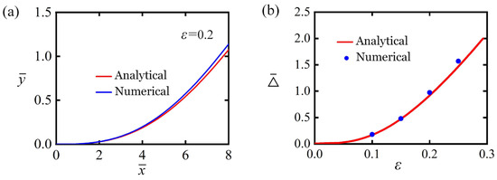
Figure 3.
The comparison between analytical solutions and numerical solutions. (a) Strip profile for . (b) Variation of with . The comparison of the analytical and numerical solutions shows good agreement.
3. Two Motion Modes and Mechanism of Self-Adhesion
This section explores two distinct motion modes of light-powered self-adhesion oscillator—the static mode and the self-adhesion mode—and provides a mechanistic analysis of the self-adhesion phenomenon.
3.1. Two Motion Modes
Equations (32) to (44) govern transitions between adhesion-off and adhesion-on states in the self-adhesion oscillator. To investigate self-adhesion behavior, we establish baseline dimensionless parameters from experimental data [79,82,86,88,89,90,91,92,93,94,95]. Table 1 summarizes typical material properties and geometric parameters, with corresponding dimensionless quantities provided in Table 2. These parameter values are subsequently employed to analyze self-peeling dynamics under steady illumination. It is worth noting that the adhesion parameters between the elastic strip and the adhesive substrate can vary significantly depending on factors such as the molecular type of the selected strip material, the smoothness of the substrate, or the potential use of additional adhesives. Experimental investigations can flexibly adjust these parameters as needed. Additionally, the use of dimensionless system parameters in the model enhances its scalability and broadens its applicability in terms of both material properties and geometric parameters.

Table 1.
Material properties and geometric parameters.

Table 2.
Dimensionless parameters.
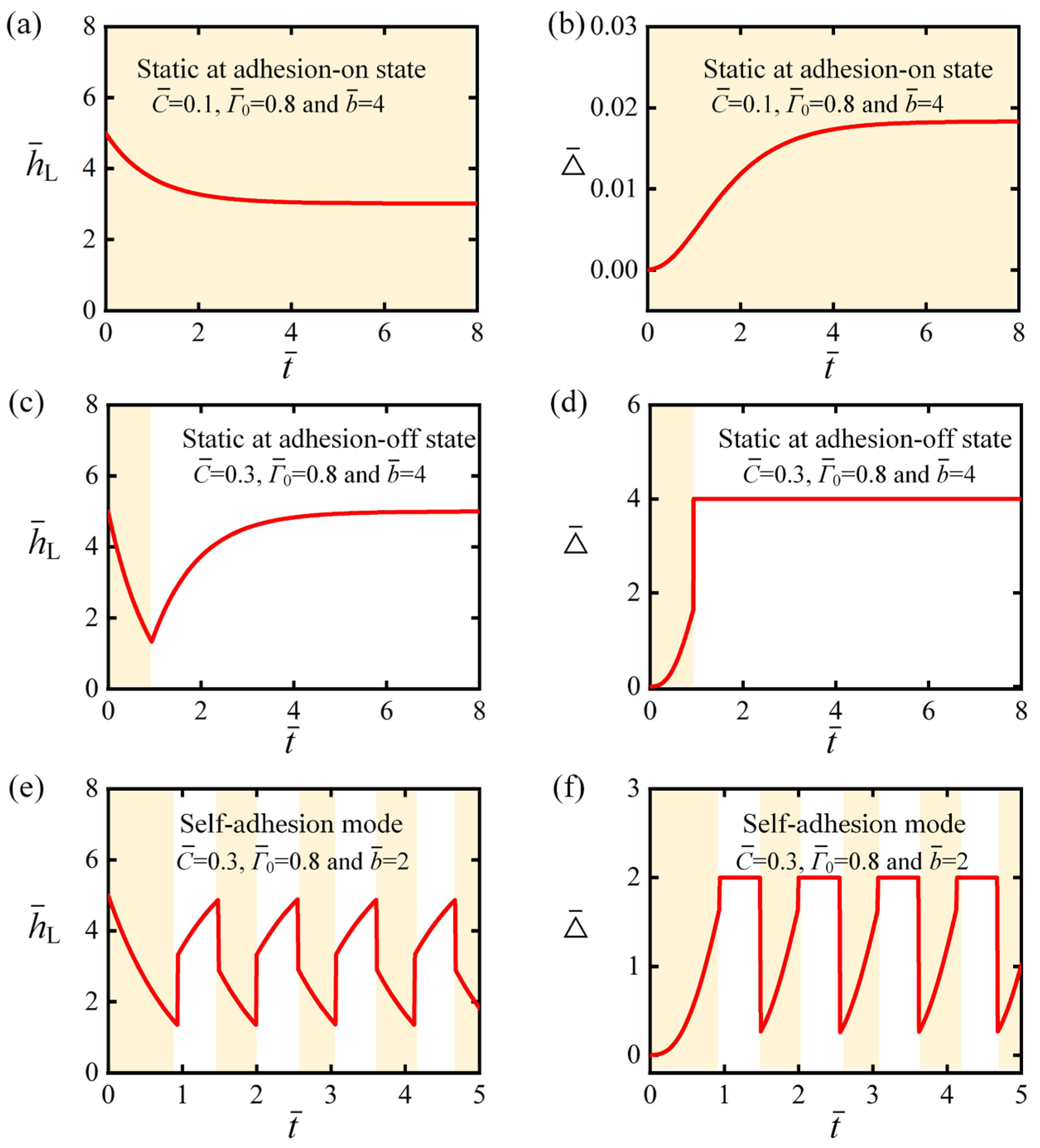
Figure 4 illustrates the dynamic temporal evolution of the light-powered self-adhesion in peeling strip under two distinct motion modes, with specific dimensionless photothermal contraction coefficients , interfacial strength , and distance of the baffle . Characteristic parameters include: , , , and . Yellow shading indicates illumination zones. For certain values of , and , the weight’s submerged length consistently decreases in a smooth, monotonic manner toward stabilization. Meanwhile, the strip’s vertical peeling displacement reaches a stable equilibrium, remaining in a persistent adhesion-on state, this represents the static mode (Figure 4a,b). In contrast, for other values of , and , weight’s submerged length first gradually decreases, then suddenly increases, before slowly rising toward a balanced value. The strip’s vertical peeling displacement initially shows a gradual increase, followed by a sharp jump, and finally stabilizes, indicating that the strip eventually rests in the adhesion-off state. This motion mode also falls under the category of a static mode (Figure 4c,d). For further combinations of , and , weight’s submerged length undergoes phase-locked alternations: a controlled gradual decline → a sharp, abrupt surge → a modulated decline → and a final, sharp drop. The strip’s vertical peeling displacement experiences a pronounced cyclic progression: a subtle, gradual increase → a sudden, accelerated surge → a sustained steady-state → followed by a rapid, sharp decline. These autonomous periodic oscillations represent continuous, reversible transitions between adhesion-on and adhesion-off states under constant steady illumination, defining the self-adhesion mode (Figure 4e,f). It is worth noting that Figure 3 presents the theoretical predictions based on Equations (32) to (44). Certain factors in real-world scenarios, which are not considered in the theoretical model, may have a quantitative, rather than qualitative, impact on the results.
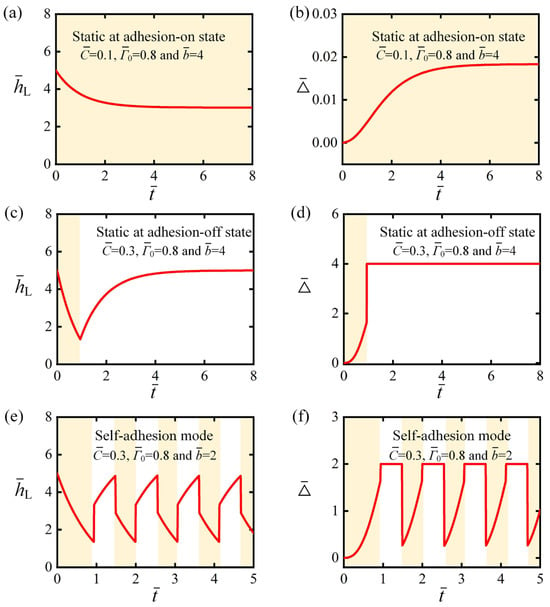
Figure 4.
Temporal evolution of the self-adhesion oscillator under two distinct motion modes. Temporal evolution of (a) and (b) for , and . Temporal evolution of (c) and (d) for , and . Temporal evolution of (e) and (f) for , and . Under steady illumination, the self-adhesion oscillator displays two distinct dynamic responses: a static mode and a self-adhesion mode. Yellow shading indicates illumination zones.
It is worth mentioning that energy conversion efficiency is a key indicator of self-oscillating systems. In this work, the energy conversion efficiency can be simply estimated by the ratio of the maximum gravitational potential energy gained by the weight to the light energy . To calculate the light energy within one cycle, the illuminated area is taken as covering the LCE fiber, where the minimum illumination width can be roughly equal to the cross-sectional thickness of the LCE fiber. Thus, the optical energy released by the light source in one cycle is , and the increment of the weight’s gravitational potential energy is . Consequently, the energy conversion efficiency can be expressed as
Referring to the typical values of the self-adhesive system: , , , , , , and and the typical cases in Figure 4e,f, the energy conversion efficiency is estimated to be approximately 1%. However, in real-world scenarios, due to the inability to precisely control the illuminated area, the energy conversion efficiency is lower than the calculated result. Therefore, the light-powered self-adhesion oscillator may not be suitable for scenarios requiring high energy transfer efficiency.
3.2. Mechanism of Self-Adhesion
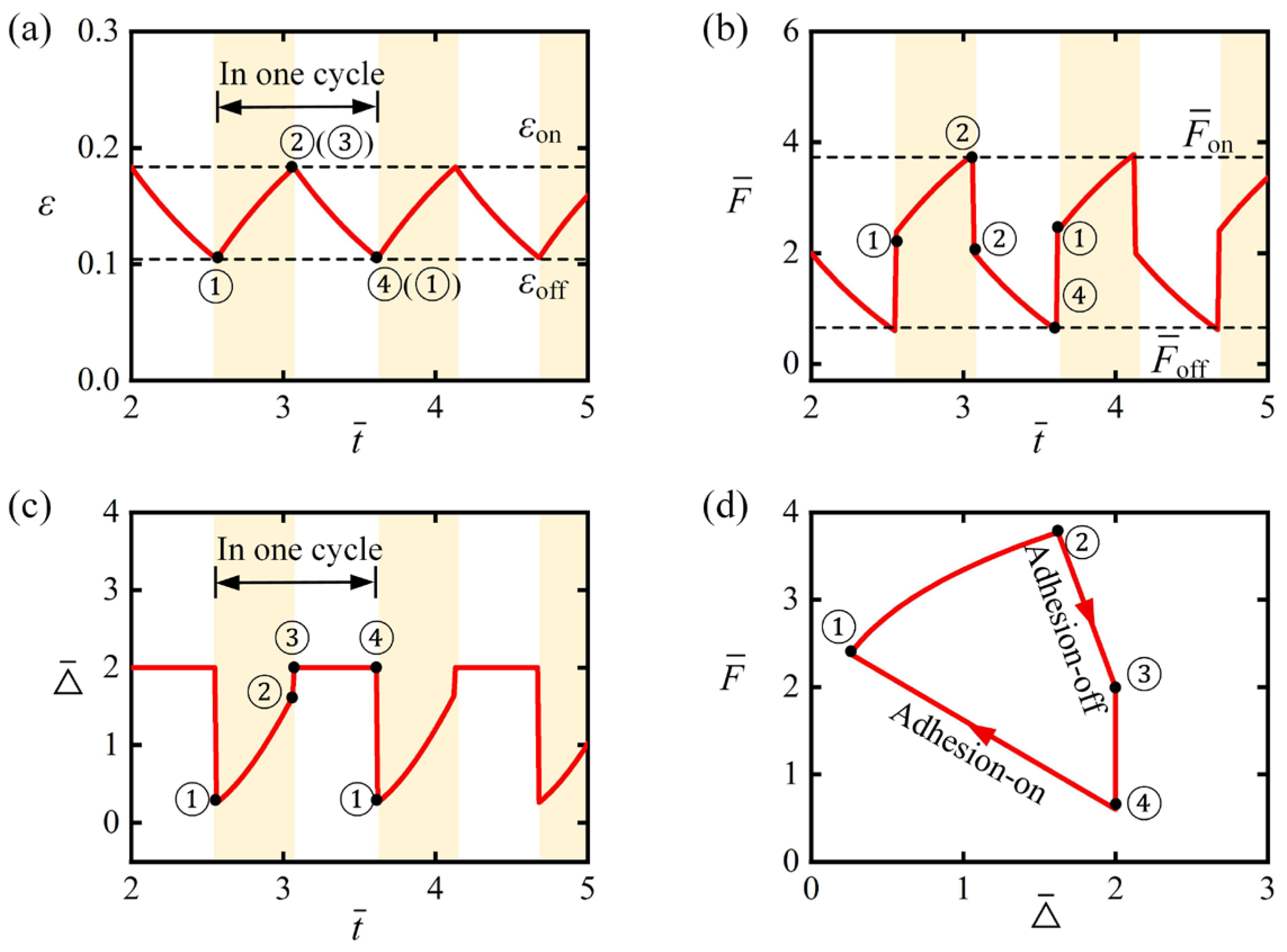
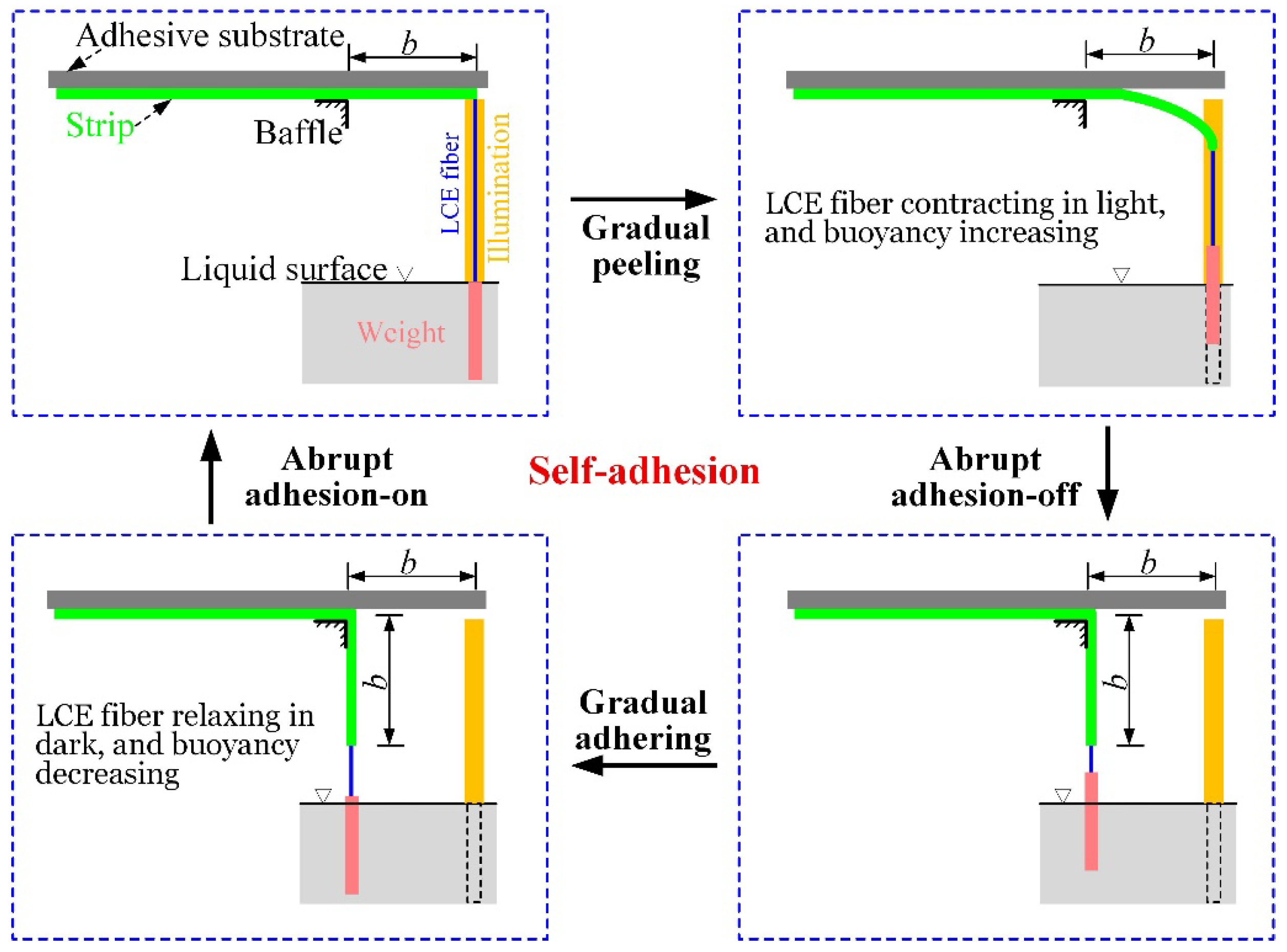
Previous analysis identified two distinct motion modes for the light-powered self-adhesion of peeling strip: static mode and self-adhesion mode. This section examines the self-adhesion mechanism through typical parameter calculations. Figure 5a displays the temporal evolution of the fiber’s photothermal contraction , which exhibits periodic variation under conditions corresponding to Figure 4e,f. Yellow shading indicates illumination zones. When , the LCE remains illuminated while the strip maintains adhesion-on state with the substrate; evolves continuously from point ① to ② as detachment force (Figure 5b) and vertical peeling displacement (Figure 5c) synchronously complete ①→② evolution. When reaches , adhesion-on-to-off transition occurs: abruptly surges ②→③ while drops sharply ②→③, displacing the LCE fiber from illumination. Subsequently, decreases from ③→④ with corresponding changes in and (Figure 5b,c). At , the strip re-adhesion initiates: plunges steeply ④→① while the LCE fiber re-enters illumination. The clockwise limit cycle (trajectory ①→②→③→④→①) confirms periodic self-adhesion under steady illumination (Figure 5d). Figure 6 shows snapshots of the peeling strip during one cycle of self-adhesion. The results indicate that the peeling strip undergoes an abrupt transition between the adhesion-on and adhesion-off states, with the LCE fiber switching between the illuminated and dark zones. The self-adhesion oscillator exhibits periodic self-adhesion behavior.
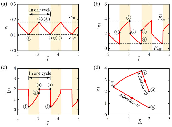
Figure 5.
Mechanism of the light-powered self-adhesion in peeling strip. Temporal evolution of (a) , (b) and (c) . (d) Limit cycle between and . These factors collectively demonstrate the self-adhesion dynamics driven by periodic exposure to constant light, coupled with abrupt transitions between the adhesion-on and adhesion-off states. Yellow shading indicates illumination zones.
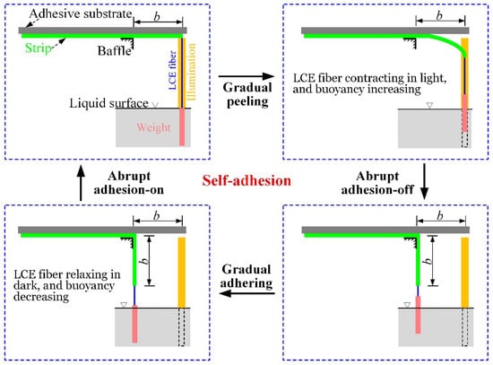
Figure 6.
Snapshots of the light-powered self-adhesion oscillator during one cycle of self-adhesion. This cyclic process sustains a four-stage oscillation: gradual peeling, abrupt adhesion-off, gradual adhering, and abrupt adhesion-on.
4. Regulating the Transition Between Adhesion-On and Adhesion-Off States
To better understand the system’s dynamic behavior, it is essential to examine how system parameters affect the transition between adhesion-on and adhesion-off states.
4.1. Transition from Adhesion-On to Adhesion-Off
In the adhesion-on state, the LCE fiber is continuously heated and contracted, resulting in an increasing detachment force. From Equation (38), it is evident that the critical photothermal contraction threshold is influenced by six parameters: , , , , and . If the photothermal contraction exceeds the critical threshold, the transition from adhesion-on to adhesion-off can be triggered.
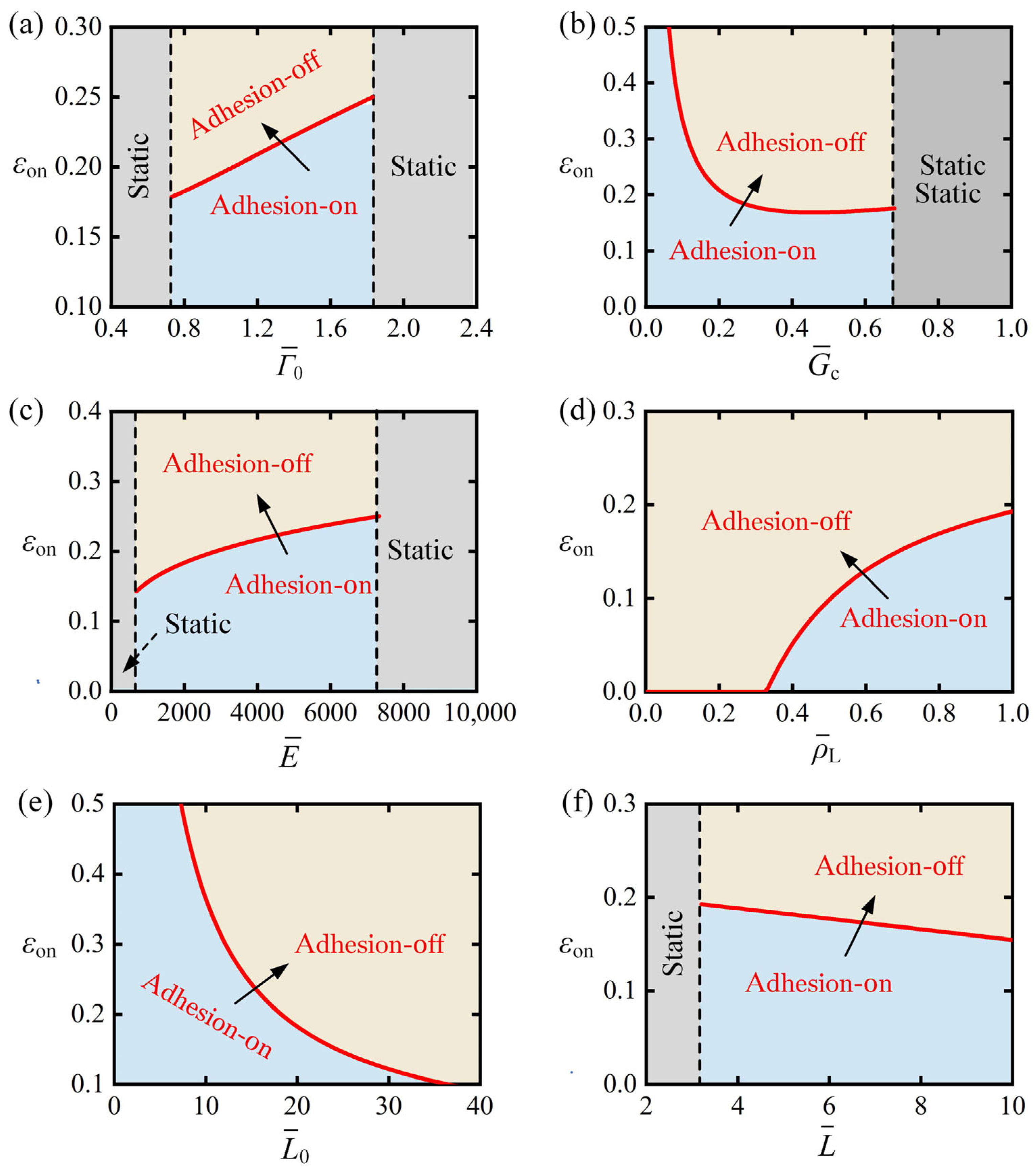
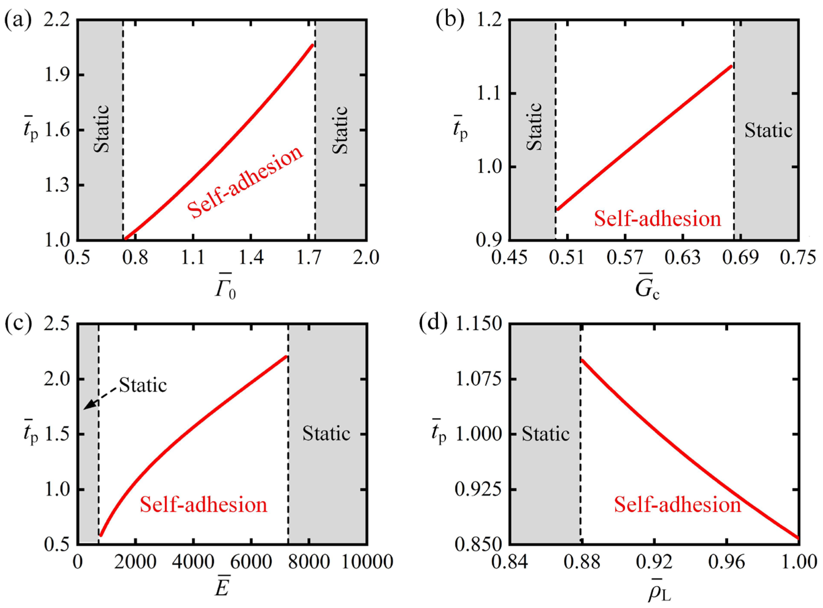
Figure 7 systematically explores parametric variations in , , , , and on the photothermal contraction threshold required to trigger adhesion-on to adhesion-off transitions. Figure 7a demonstrates the influence of interfacial strength under fixed parameters , , , , and . Results indicate that for interfacial strength , the transition from the adhesion-on state to the adhesion-off state cannot be triggered, as the separation between the strip and the substrate has not reached the critical separation distance. As increases, grows monotonically because enhanced adhesion necessitates greater photothermal contraction to: (i) reduce submerged length of the weight and (ii) increase detachment force to the critical detachment force , thereby enabling state transition from adhesion-on to adhesion-off. At , this mechanism fails—after full emergence of the weight from the liquid, detachment force plateaus and further increases prevent transitions, locking the system in static mode. Notably, the variation in interface toughness with respect to critical contraction threshold follows the same trend as that of interfacial strength , as shown in Figure 7b. This similarity arises because both parameters are characteristic of the adhesive strength between the strip and the substrate.
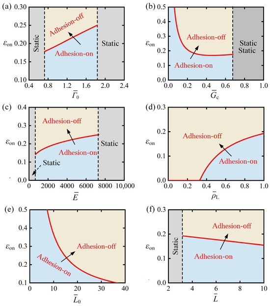
Figure 7.
Effect of parameters on the photothermal contraction threshold . (a) versus , (b) versus , (c) versus , (d) versus , (e) versus , (f) versus . Analysis reveals increases monotonically with , , and , while decreasing monotonically with and . Arrow indicates transition from adhesion-on to adhesion-off.
Figure 7c demonstrates the effect of bending stiffness on the photothermal contraction threshold under fixed parameters , , , , and . Result indicates that for bending stiffness , the transition from the adhesion-on state to the adhesion-off state cannot be triggered, as the separation between the strip and the substrate has not reached the critical separation distance. When , it exhibits that monotonically increases with increasing , as heightened deformation resistance necessitates greater detachment force to induce strip bending sufficient to achieve the critical interfacial separation required for adhesion failure and transition from adhesion-on to adhesion-off state. When , the weight fully emerges from the liquid with maximum detachment force , yet detachment remains unattainable, preventing adhesion state transitions and resulting in permanent static-mode operation.
Figure 7d illustrates the effect of the buoyancy coefficient on the photothermal contraction threshold under fixed parameters , , , , and . From the figure, it can be observed that when , . This phenomenon can be explained as follows: for smaller buoyancy coefficients, the minimum detachment force when the weight is fully immersed in the liquid exceeds the critical detachment force . As a result, regardless of whether the LCE fiber contracts, the transition from the adhesion-on to the adhesion-off state can be triggered. Subsequently, increases monotonically with the increase in . This is because, as the buoyancy coefficient increases, the buoyant force acting on the weight in the liquid also increases, necessitating a greater contraction of the LCE fiber to lift the weight from the liquid, thereby enhancing the detachment force.
Figure 7e illustrates the effect of the initial length of the LCE fiber on the photothermal contraction threshold , with fixed parameters , , , , and . From the figure, it can be observed that as increases, decreases monotonically. This is because, in the given strip-substrate system, the critical detachment force remains constant. As a result, the total contraction required to trigger the transition from the adhesion-on to the adhesion-off state is fixed. Thereby, increasing reduces the demand for the LCE contraction rate, as only the product of the two values needs to meet the total contraction threshold for the transition from adhesion-on to adhesion-off.
Figure 7f demonstrates how weight length influences the photothermal contraction threshold , with fixed parameters , , , , and . For , the system operates in static mode. This is because a small means that the weight exerts a smaller gravitational force. When the detachment force equals the gravitational force of the weight, it is still less than the critical detachment force , preventing the transition from the adhesion-on to the adhesion-off state from being triggered. When , decreases monotonically with increasing . This inverse relationship arises because constant in the strip-substrate system entails that greater gravitational force proportionally amplifies detachment force , thereby diminishing the requisite contraction magnitude to achieve critical interfacial separation and activate state switching.
4.2. Transitions from Adhesion-Off to Adhesion-On
In the adhesion-on state, the LCE fiber undergoes continuous cooling and recovery contraction, leading to an increase in the detachment force. According to Equation (39), the critical photothermal contraction threshold is influenced by six parameters: , , , , and . If the photothermal contraction falls below this critical threshold, the system will transition from the adhesion-off to the adhesion-on state.
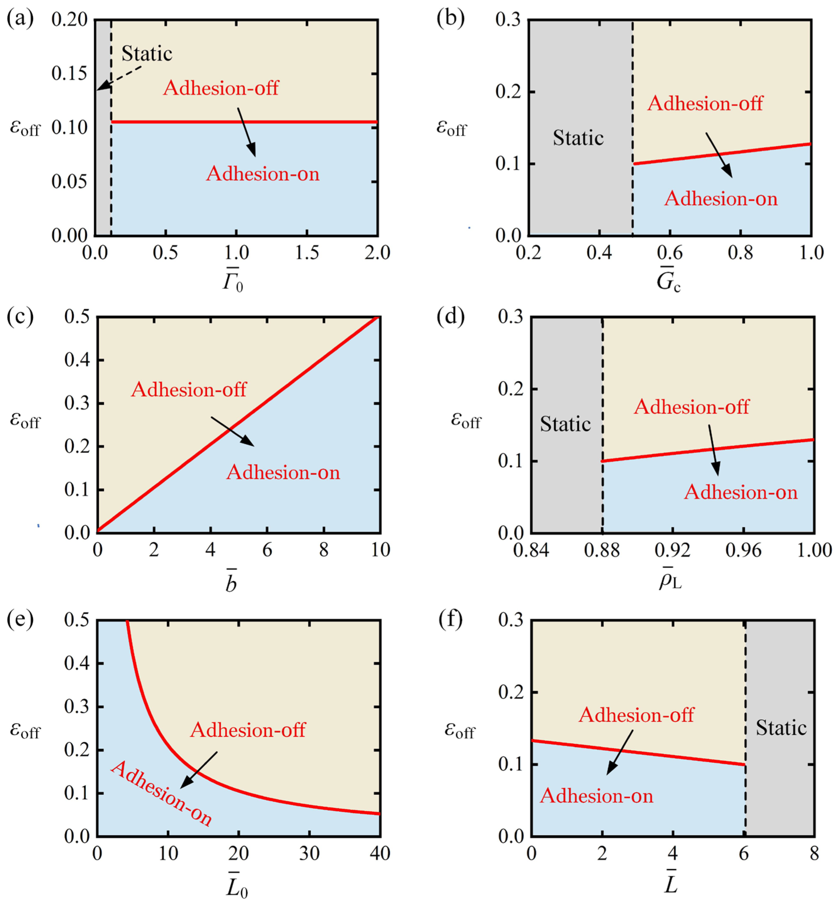
Figure 8 provides a systematic analysis of how variations in the parameters , , , , and affect the photothermal contraction threshold required to initiate the transition from adhesion-off to adhesion-on. Figure 8a illustrates the effect of interfacial strength under fixed parameters , , , , and . The results show that the system remains in a static mode for . This is because a small implies a weak adhesive force between the strip and the substrate. Even when the LCE fiber fully recovers its contraction, the minimum detachment force still exceeds the critical attachment force , preventing the system from transitioning from the adhesion-off state to the adhesion-on state. As increases, the photothermal contraction threshold also rises. This is because stronger interfacial strength results in a more robust adhesive force between the strip and the substrate, which in turn increases the , enabling the LCE strip to transition from adhesion-off to adhesion-on under higher photothermal contraction conditions. It is worth noting that the change in interface toughness with respect to the critical contraction threshold follows a similar trend to that of interfacial strength , as depicted in Figure 8b. This similarity is due to both parameters being indicative of the adhesive strength between the strip and the substrate.
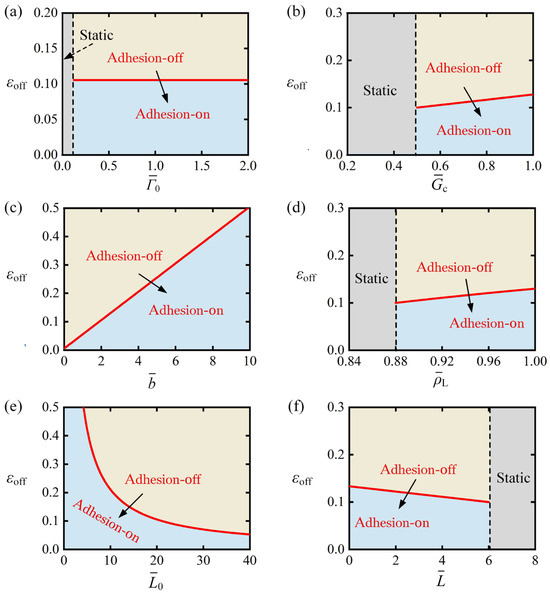
Figure 8.
Effect of parameters on the photothermal contraction threshold . (a) versus , (b) versus , (c) versus , (d) versus , (e) versus , (f) versus . Analysis reveals increases monotonically with , , and , while decreasing monotonically with and . Arrow indicates transition from adhesion-off to adhesion-on.
Figure 8c shows the impact of baffle distance on the photothermal contraction threshold under fixed parameters: , , , , and . The results reveal that the threshold increases monotonically with the baffle distance . This trend occurs because an increase in baffle distance corresponds to a longer detachment length of the strip, allowing a greater portion of the weight to immerse in the liquid. As a result, the LCE fiber can achieve the required reduction in contraction recovery, which reduces the detachment force to the critical attachment force. This, in turn, increases the photothermal contraction threshold , enabling the transition from the adhesion-off state back to the adhesion-on state.
Figure 8d demonstrates the influence of the buoyancy coefficient on the photothermal contraction threshold under the following fixed parameters: , , , , , and . The results reveal that when , the system maintains a static state. For lower buoyancy coefficients, complete recovery of photothermal contraction causes the minimum detachment force , however the minimum detachment force still exceeds the critical attachment force , preventing transition to the adhesion-on state. When , as increases, shows a corresponding increase. This behavior occurs because at higher buoyancy coefficients , the LCE fiber experiences a more significant reduction in detachment force when recovering the same contraction magnitude. Consequently, the system can maintain larger photothermal contractions while allowing the detachment force to decrease below the critical attachment force .
Figure 8e demonstrates the relationship between the initial length of the LCE fiber and the photothermal contraction threshold under constant parameters: , , , , and . The results exhibit a monotonic decrease in with increasing , which arises from the system’s fixed critical attachment force and constant total contraction requirement for state transition in the strip-substrate configuration. Consequently, longer initial fiber lengths require proportionally smaller photothermal contractions to reduce the detachment force to the critical threshold , as the absolute contraction needed to achieve the adhesion state transition remains unchanged in this system. This inverse proportionality between and directly results from the constant critical force condition and fixed displacement requirement governing the interfacial adhesion behavior.
Figure 8f demonstrates the influence of weight length on the photothermal contraction threshold under fixed parameters: , , , , and . The results reveal that decreases monotonically as weight length increases, due to the greater gravitational force exerted by the larger weight, which generates stronger detachment forces on the strip. As a result, the LCE fiber needs to recover more contraction to submerge the weight into the liquid and reduce the detachment force. When exceeds 6, the system enters a static mode. This happens because, for sufficiently heavy weights, the detachment force remains above the critical attachment force even after complete photothermal contraction recovery, thus preventing the transition from the adhesion-off to adhesion-on state.
5. Regulation of the Self-Adhesion Period
Next, the self-adhesion period is studied. One cycle of self-adhesion consists of four stages: gradual peeling, abrupt adhesion-off, gradual adhering, and abrupt adhesion-on. Given the negligible duration of the abrupt transition between detachment and attachment relative to the overall cycle period, the self-peeling period is defined as the total duration of the adhesion-on and adhesion-off states. By explicitly solving Equations (40) and (41), the self-peeling period can be determined. It is worth noting that, in practical scenarios, the inertia of the strip may reduce the durations of both the adhesion-on and adhesion-off states. Furthermore, the abrupt durations of adhesion-off and adhesion-on are not exactly zero, which may result in a quantitative difference between the self-peeling period in real-world situations and the calculated results in this study. For simplicity, this work only considers the impact of the durations of the adhesion-on and adhesion-off states.
It is evident that the self-peeling period depends on dimensionless parameters such as , , , , , , and . Notably, , and represent the adhesion characteristics between the strip and the substrate, while captures the buoyancy properties of the liquid. Therefore, , , and are classified as material properties. In contrast, , , and reflect the geometric properties of the system, specifically its length characteristics, and are categorized as geometric parameters. It is worth noting that although represents the deformability of the LCE material, it always acts in conjunction with , primarily influencing the change in the length of the LCE fiber. Thus, is classified under geometric parameters. The following discussion explores how the self-peeling period varies with the material properties and geometric parameters. It is worth mentioning that Equations (40) and (41) demonstrate that the self-adhesion period is determined by the coupling of system parameters. To focus on qualitatively analyzing the variation in the self-adhesion period, this work examines the effect of individual parameter changes on it.
5.1. Regulation of the Self-Adhesion Period by Material Properties
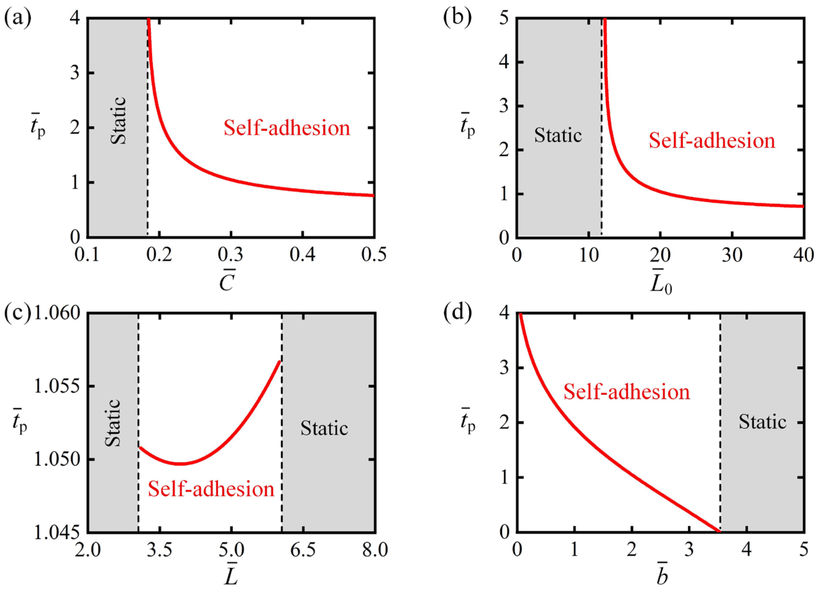
Figure 9 systematically examines parametric dependence of self-adhesion period on material characteristics: , , and . Figure 9a presents the relationship between the self-adhesion period and interfacial strength under fixed parameters: , , , , , and . The system exhibits two distinct behavioral regimes based on values. For or , the system remains in static mode. For too small interfacial strength, the LCE fiber requires minimal or no contraction to transition from the adhesion-on to adhesion-off state, after which insufficient interfacial adhesion prevents recovery to the adhesion-on state. Conversely, for too large interfacial strength, even with the maximum photothermal contraction of the LCE fiber, the detachment force remains below the critical detachment threshold, thus maintaining a permanent adhesion-on state. When , the system demonstrates self-adhesion behavior with a monotonically increasing period as increases. This trend results from enhanced interfacial adhesion requiring greater photothermal contraction to generate sufficient detachment force for state transition, thereby prolonging both the transition duration and overall self-adhesion cycle period. Notably, the effect of interface toughness on self-adhesion period follows similar trends to , as both parameters reflect interfacial adhesion strength, as shown in Figure 9b, where , the system demonstrates self-adhesion behavior with a monotonically increasing period as increases for .
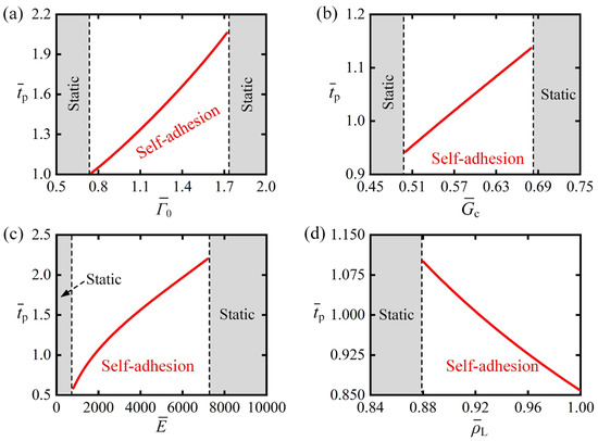
Figure 9.
Parametric dependence of self-adhesion period on material characteristics: (a) interfacial strength , (b) interface toughness , (c) bending stiffness , and (d) buoyancy coefficient . Analysis reveals monotonically elevates with increasing , , and , while exhibiting inverse proportionality to .
Figure 9c illustrates the variation in self-adhesion period under different bending stiffness with fixed parameters: , , , , , and . The system exhibits two distinct regimes: a static mode when or , and a self-adhesion mode within the range . In the self-adhesion mode, the self-adhesion period increases monotonically as increases. This behavior can be explained through the interfacial adhesion mechanics: The critical detachment force increases with , requiring greater critical contraction for the adhesion-on to adhesion-off transition. Consequently, the LCE fiber needs more time to reduce the contraction strain from to the critical value for the reverse transition. These combined effects result in the observed prolongation of the self-adhesion period with increasing .
Figure 9d demonstrates the dependence of the self-adhesion period on the buoyancy coefficient under fixed parameters: , , , , , and . The system exhibits three distinct behavioral regimes based on values. For , the system remains in static mode. For too small , the detachment force in the adhesion-off state remains above the critical attachment force , inhibiting the transition back to adhesion-on state. When , the system exhibits self-adhesion behavior with a monotonically decreasing period as increases. This trend arises because larger values amplify buoyancy variations during the weight’s immersion depth changes, thereby reducing both the heating and cooling durations required for the LCE fiber to complete one self-adhesion cycle.
5.2. Regulation of the Self-Adhesion Period by Geometric Parameters
Figure 10 provides a systematic analysis of how the self-adhesion period depends on geometric characteristics: photothermal contraction coefficient , LCE fiber’s initial length , weight’s length and baffle distance . Figure 10a presents the relationship between the self-adhesion period and photothermal contraction coefficient under fixed parameters: , , , , , and . The system exhibits two distinct behavioral regimes based on the photothermal contraction coefficient values . For , the system remains in static mode. This occurs because, for too small , even with the maximum photothermal contraction of the LCE fiber, the detachment force remains below the critical detachment threshold, maintaining a permanent adhesion-on state. When , the system exhibits self-adhesion behavior with a period that monotonically decreases as the contraction coefficient increases. This trend is due to larger photothermal contraction, meaning the LCE fiber can reach the critical contraction threshold more quickly, reducing the time spent in the illuminated region. The recovery time in the dark zone, governed by the transition from the critical contraction threshold to , is independent of the contraction coefficient. Therefore, the self-adhesion period decreases monotonically with an increase in the contraction coefficient . It is noteworthy that the initial length of the LCE fiber influences the fiber’s contraction and recovery in a manner similar to the photothermal contraction coefficient. As a result, the effect of on follows the same trend as , as shown in Figure 10b, where the critical initial length that triggers the phase transition between the static mode and the self-adhesion mode is approximately.
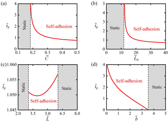
Figure 10.
Parametric dependence of self-adhesion period on geometric parameters: (a) photothermal contraction coefficient , (b) LCE fiber’s initial length , (c) weight’s length , and (d) baffle distance . Analysis demonstrates a monotonic decrease in with increasing , , and , while it decreases first and then increases as increases.
Figure 10c illustrates the variation in the self-adhesion period with respect to the weight length , while keeping the parameters , , , , , and fixed. The system exhibits two distinct regimes: a static mode when or , and a self-adhesion mode within the range . In the self-adhesion mode, the self-adhesion period decreases first and then increases as increases. This is because, as increases, LCE fiber requires less time to complete the desired contraction under illumination but more time to restore contraction in the dark state. Since the self-adhesion period is the sum of durations and , this results in non-monotonic changes with increasing .
Figure 10d shows how the self-adhesion period varies with the baffle distance under fixed parameters: , , , , , and . The system exhibits two distinct regimes depending on the baffle distance values. The results indicate that in scenarios with , the system remains in static mode. This is because, for excessively large values, when the system transitions from the adhesion-on state to the adhesion-off state, the detachment force reaches the attachment threshold and immediately switches back to the adhesion-on state. As a result, the LCE is unable to cool down and absorb light energy again, which prevents the system from maintaining periodic motion. When , the system shows self-adhesion behavior, with the period decreasing monotonically as the baffle distance increases. This behavior occurs because larger baffle distances cause a further reduction in the detachment force during the transition from adhesion-on to adhesion-off, which in turn leads to shorter cooling times for the LCE fibers. Consequently, the system can switch more rapidly back to the adhesion-on state, thereby reducing the self-adhesion period.
6. Conclusions
In nature, the tendrils of climbing plants can detach temporarily under external forces and reattach when the force diminishes. Inspired by this dynamic adhesion-detachment mechanism, we introduce a novel light-powered self-adhesion oscillator, comprising an elastic strip–substrate system and a weight suspended by a photo-responsive LCE fiber. By integrating a nonlinear beam deformation model with Dugdale’s cohesive law, we develop a dynamic framework to model the self-adhesion behavior of the elastic strip. Quasi-static analysis identifies two distinct operational modes: static and self-adhesion. With continuous light exposure, the contraction of the LCE fiber increases the detachment force on the strip, triggering a rapid transition from the adhesion-on to adhesion-off state. In the adhesion-off state, the fiber’s recovery reduces the detachment force, swiftly returning the system to the adhesion-on state.
Furthermore, the critical conditions for initiating self-adhesion and controlling the strategy of the oscillation period are explicitly derived. The self-adhesion behavior is governed by several essential parameters, including the interfacial strength , interface toughness , bending stiffness , buoyancy coefficient , the contraction coefficient , initial length , weight’s length , and baffle distance . Parameter analysis indicates that the self-adhesion period increases monotonically with , , and , while it decreases with , , , and ; additionally, decreases first and then increases as increases. Notably, in real-world settings, unavoidable factors—including the elastic deformation of LCE fibers, boundary effects of baffles on strip delamination, and damping of heavy objects in liquids—lead to quantitative (rather than qualitative) discrepancies between theoretical calculations and real-world results.
The self-adhesion system offers advantages such as well-defined reversible motion trajectories, precise control over the performance of the self-adhesion oscillator and structural simplicity. To advance this research, the next stage should focus on experimentally validating the self-adhesion phenomenon and exploring practical applications. However, several limitations currently hinder system optimization and targeted deployment: adhesive fatigue between the strip and substrate, the slow thermal relaxation rate of LCE fiber, and low energy conversion efficiency of the system. Despite these challenges, we anticipate that this work will lay foundational insights for future applications, such as self-healing adhesives, search and rescue operations, and military technologies.
Author Contributions
Conceptualization, D.G.; Methodology, D.G.; Validation, S.W.; Data curation, Y.H.; Writing—original draft, S.W.; Writing—review and editing, D.G.; Supervision, D.G. All authors have read and agreed to the published version of the manuscript.
Funding
This research was funded by Anhui Provincial Natural Science Foundation (2208085Y01), Anhui Provincial Natural Science Foundation (2008085QA23), National Natural Science Foundation of China (12172001) and University Natural Science Research Project of Anhui Province (KJ2020A0449).
Data Availability Statement
No new data were created or analyzed in this study.
Acknowledgments
The authors acknowledge the financial support from Anhui Provincial Natural Science Foundation.
Conflicts of Interest
The authors declare no conflicts of interest.
References
- Li, J.J.; Mou, L.L.; Liu, Z.F.; Zhou, X.; Chen, Y.S. Oscillating light engine realized by photothermal solvent evaporation. Nat. Commun. 2022, 13, 5621. [Google Scholar] [CrossRef]
- Alipanah, Z.; Zakerhamidi, M.S.; Ranjkesh, A. Light-fueled self-oscillation of liquid crystal polymer network: Effect of photostabilizers. J. Appl. Polym. Sci. 2024, 141, e54923. [Google Scholar] [CrossRef]
- Wang, J.C.; Song, T.F.; Zhang, Y.H.; Liu, J.G.; Yu, M.M.; Yu, H.F. Light-driven autonomous self-oscillation of a liquid-crystalline polymer bimorph actuator. J. Mater. Chem. C 2021, 9, 12573–12580. [Google Scholar] [CrossRef]
- Zhao, J.; Zhang, Z.R.; Sun, X.D.; Zuo, W.; Li, K. Multi-modal self-sustained motions of a silicone oil paper disc on a surface driven by hot steam. Chaos Soliton Fract. 2025, 191, 115898. [Google Scholar] [CrossRef]
- Yan, Z.; Wang, Y.L.; Bian, M.X.; Wang, M.; Zhou, X.; Yin, S.G.; Qin, W.J.; Liu, Z.F. Transformable thin-film robots capable of crawling, rolling, and oscillation. Appl. Mater. Today 2022, 28, 101514. [Google Scholar] [CrossRef]
- Li, Z.W.; Myung, N.V.; Yin, Y.D. Light-powered soft steam engines for self-adaptive oscillation and biomimetic swimming. Sci. Rob. 2021, 6, eabi4523. [Google Scholar] [CrossRef]
- Lv, X.D.; Wang, W.Z.; Clancy, A.J.; Yu, H.F. High-speed, heavy-load, and direction-controllable photothermal pneumatic floating robot. ACS Appl. Mater. Interfaces 2021, 13, 23030–23037. [Google Scholar] [CrossRef]
- Guo, K.X.; Yang, X.H.; Zhou, C.; Li, C. Self-regulated reversal deformation and locomotion of structurally homogenous hydrogels subjected to constant light illumination. Nat. Commun. 2024, 15, 1694. [Google Scholar] [CrossRef]
- Fu, L.; Zhao, W.Q.; Ma, J.Y.; Yang, M.Y.; Liu, X.M.; Zhang, L.; Chen, Y. A humidity-powered soft robot with fast rolling locomotion. Research 2022, 2022, 9832901. [Google Scholar] [CrossRef]
- Wang, Q.; Wu, Z.; Li, J.; Guo, J.B.; Yin, M.Z. Spontaneous and continuous actuators driven by fluctuations in ambient humidity for energy-harvesting applications. ACS Appl. Mater. Interfaces 2022, 14, 38972–38980. [Google Scholar] [CrossRef]
- Ge, D.L.; Bao, B.; Chen, H.M.; Li, K. A liquid crystal elastomer-based generator using light-powered self-oscillations. Chaos Soliton Fract. 2025, 199, 116690. [Google Scholar] [CrossRef]
- Chang, L.F.; Wang, D.P.; Huang, Z.S.; Wang, C.F.; Torop, J.; Li, B.; Wang, Y.J.; Hu, Y.; Aabloo, A. A versatile ionomer-based soft actuator with multi-stimulus responses, self-sustainable locomotion, and photoelectric conversion. Adv. Funct. Mater. 2023, 33, 2212341. [Google Scholar] [CrossRef]
- Yang, L.L.; Chang, L.F.; Hu, Y.; Huang, M.J.; Ji, Q.X.; Lu, P.; Liu, J.Q.; Chen, W.; Wu, Y.C. An autonomous soft actuator with light-driven self-sustained wavelike oscillation for phototactic self-locomotion and power generation. Adv. Funct. Mater. 2020, 30, 1908842. [Google Scholar] [CrossRef]
- Zhai, F.; Feng, Y.Y.; Li, Z.Y.; Xie, Y.X.; Ge, J.; Wang, H.; Qiu, W.; Feng, W. 4D-printed untethered self-propelling soft robot with tactile perception: Rolling, racing, and exploring. Matter 2021, 4, 3313–3326. [Google Scholar] [CrossRef]
- Liu, J.Q.; Xu, L.L.; Ji, Q.X.; Chang, L.F.; Hu, Y.; Peng, Q.Y.; He, X.D. A MXene-based light-driven actuator and motor with self-sustained oscillation for versatile applications. Adv. Funct. Mater. 2024, 34, 2310955. [Google Scholar] [CrossRef]
- Preston, D.J.; Rothemund, P.; Jiang, H.J.; Nemitz, M.P.; Rawson, J.; Suo, Z.G.; Whitesides, G.M. Digital logic for soft devices. Proc. Nat. Acad. Sci. USA 2019, 116, 7750–7759. [Google Scholar] [CrossRef] [PubMed]
- Helou, C.E.; Hyatt, L.P.; Buskohl, P.R.; Harne, R.L. Intelligent electroactive material systems with self-adaptive mechanical memory and sequential logic. Proc. Nat. Acad. Sci. USA 2024, 121, e2317340121. [Google Scholar] [CrossRef] [PubMed]
- Ge, F.J.; Zhao, Y. A new function for thermal phase transition-based polymer actuators: Autonomous motion on a surface of constant temperature. Chem. Sci. 2017, 8, 6307–6312. [Google Scholar] [CrossRef]
- Zhu, Q.L.; Liu, W.X.; Khoruzhenko, O.; Breu, J.; Bai, H.Y.; Hong, W.; Zheng, Q.; Wu, Z.L. Animating hydrogel knotbots with topology-invoked self-regulation. Nat. Commun. 2024, 14, 300. [Google Scholar] [CrossRef]
- Zhu, Q.L.; Liu, W.X.; Khoruzhenko, O.; Breu, J.; Bai, H.Y.; Hong, W.; Zheng, Q.; Wu, Z.L. Closed twisted hydrogel ribbons with self-sustained motions under static light irradiation. Adv. Mater. 2024, 36, 2314152. [Google Scholar] [CrossRef]
- Bai, C.; Kang, J.; Wang, Y.Q. Kirigami-Inspired Light-Responsive Conical Spiral Actuators with Large Contraction Ratio Using Liquid Crystal Elastomer Fiber. ACS Appl. Mater. 2025, 17, 14488–14498. [Google Scholar] [CrossRef] [PubMed]
- Bai, C.; Kang, J.; Wang, Y.Q. Light-induced wrinkling in annulus anisotropic liquid crystal elastomer films. Phys. Rev. E 2025, 111, 015421. [Google Scholar] [CrossRef]
- Yang, H.X.; Yin, X.F.; Zhang, C.; Chen, B.H.; Sun, P.; Xu, Y. Weaving liquid crystal elastomer fiber actuators for multifunctional soft robotics. Sci. Adv. 2025, 11, eads3058. [Google Scholar] [CrossRef]
- Wang, L.Q.; Wei, Z.X.; Xu, Z.T.; Yu, Q.M.; Wu, Z.L.; Wang, Z.J.; Qian, J.; Xiao, R. Shape morphing of 3D printed liquid crystal elastomer structures with precuts. ACS Appl. Polym. Mater. 2023, 5, 7477–7484. [Google Scholar] [CrossRef]
- Yang, H.X.; Zhang, C.; Chen, B.H.; Wang, Z.J.; Xu, Y.; Xiao, R. Bioinspired design of stimuli-responsive artificial muscles with multiple actuation modes. Smart Mater. Struct. 2023, 32, 085023. [Google Scholar] [CrossRef]
- Kang, W.D.; Cheng, Q.; Liu, C.Y.; Wang, Z.J.; Li, D.F.; Liang, X.D. A constitutive model of monodomain liquid crystal elastomers with the thermal-mechanical-nematic order coupling. J. Mech. Phys. Solids 2025, 196, 105995. [Google Scholar] [CrossRef]
- Wang, Y.; Yin, R.; Jin, L.S.; Liu, M.Z.; Gao, Y.H.; Raney, J.; Yang, S. 3D-printed photoresponsive liquid crystal elastomer composites for free-form actuation. Adv. Funct. Mater. 2023, 33, 2210614. [Google Scholar] [CrossRef]
- Zheng, R.; Ma, L.L.; Feng, W.; Pan, J.T.; Wang, Z.Y.; Chen, Z.X.; Zhang, Y.H.; Li, C.Y.; Chen, P.; Bisoyi, H.K.; et al. Autonomous self-sustained liquid crystal actuators enabling active photonic applications. Adv. Funct. Mater. 2023, 33, 2301142. [Google Scholar] [CrossRef]
- Ren, L.Q.; He, Y.L.; Wang, B.F.; Xu, J.Y.; Wu, Q.; Wang, Z.G.; Li, W.X.; Ren, L.; Zhou, X.L.; Liu, Q.P.; et al. 4D printed self-sustained soft crawling machines fueled by constant thermal field. Adv. Funct. Mater. 2024, 34, 2400161. [Google Scholar] [CrossRef]
- Mao, T.H.; Liu, Z.Y.; Guo, X.X.; Wang, Z.F.; Liu, J.J.; Wang, T.; Geng, S.B.; Chen, Y.; Cheng, P.; Zhang, Z.J. Engineering covalent organic frameworks with polyethylene glycol as self-sustained humidity-responsive actuators. Angew. Chem. 2023, 135, e202216318. [Google Scholar] [CrossRef]
- Wu, H.Y.; Ge, D.L.; Qiu, Y.L.; Li, K.; Xu, P.B. Mechanics of light-fueled bidirectional self-rolling in a liquid crystal elastomer rod on a track. Chaos Solitons Fractals 2025, 191, 115901. [Google Scholar] [CrossRef]
- Wu, H.; Lou, J.; Dai, Y.; Zhang, B.; Li, K. Multi-scale analysis of the self-vibration of a liquid crystal elastomer fiber-spring system exposed to constant-gradient light. J. Zhejiang Univ. Sci. A 2025, 26, 652–665. [Google Scholar] [CrossRef]
- Zhao, Y.S.; Liu, Z.X.; Shi, P.J.; Chen, C.; Alsaid, Y.; Yan, Y.C.; He, X.M. Antagonistic-contracting high-power photo-oscillators for multifunctional actuations. Nat. Mater. 2025, 24, 116–124. [Google Scholar] [CrossRef] [PubMed]
- Xiang, F.; Lou, J.; Wang, J.; Chuang, K.C.; Wu, H.M.; Huang, Z.L. A self-excited bistable oscillator with a light-powered liquid crystal elastomer. Int. J. Mech. Sci. 2024, 271, 109124. [Google Scholar]
- Ge, D.L.; Bao, W.; Li, K.; Liang, H.Y. Self-oscillation-driven locomotion in a liquid crystal elastomer-based robot under constant illumination. Commun. Nonlinear Sci. Numer. Simul. 2025, 145, 108706. [Google Scholar] [CrossRef]
- Hu, Z.M.; Li, Y.L.; Lv, J.A. Phototunable self-oscillating system driven by a self-winding fifiber actuator. Nat. Commun. 2021, 12, 3211. [Google Scholar] [CrossRef] [PubMed]
- Zhou, N.Z.; Wang, M.; Huang, S.; Liu, Z.Y.; Yang, H. Multimodal self-sustainable autonomous locomotions of light-driven seifert ribbon actuators based on liquid crystal elastomers. Angew. Chem. Int. Ed. 2023, 62, e202304081. [Google Scholar]
- Sun, X.; Zhou, K.; Xu, P.B. Chaotic self-beating of left ventricle modeled by liquid crystal elastomer. Thin Walled Struct. 2024, 205, 112540. [Google Scholar] [CrossRef]
- Zeng, H.; Lahikainen, M.; Liu, L.; Ahmed, Z.; Wani, O.M.; Wang, M.; Yang, H.; Priimagi, A. Light-fuelled freestyle self-oscillators. Nat. Commun. 2019, 10, 5057. [Google Scholar] [CrossRef]
- Huang, C.Y.; Yang, F.; Li, K.; Dai, Y.T.; Yu, Y. Modeling and analysis of self-sustaining oscillation behavior of liquid crystal elastomer fiber/baffle system under stable full-field illumination. Chaos Solitons Fractals 2025, 194, 116259. [Google Scholar] [CrossRef]
- Xu, P.B.; Zhou, K.; Sun, X.; Li, K. Self-sustainable chaotic dynamics of a liquid crystal elastomer pendulum in radial linear temperature fields. Commun. Nonlinear Sci. Numer. Simul. 2025, 152, 109338. [Google Scholar] [CrossRef]
- Sun, X.; Zhou, K.; Chen, Y.Q.; Gao, J.F.; Xu, P.B. Self-oscillation chaotic motion of a liquid crystal elastomer pendulum under gradient-stabilized illumination. Chaos Soliton Fract. 2025, 193, 116128. [Google Scholar] [CrossRef]
- Zhao, J.; Wang, X.C.; Qiu, Y.L.; Chen, H.B.; Li, K. Light-powered self-swing of a bistable magnetic pendulum utilizing liquid crystal elastomer fibers. Chaos Solitons Fractals 2025, 198, 116565. [Google Scholar] [CrossRef]
- Bai, C.P.; Kang, J.T.; Wang, Y.Q. Light-induced motion of three-dimensional pendulum with liquid crystal elastomeric fiber. Int. J. Mech. Sci. 2024, 266, 108911. [Google Scholar] [CrossRef]
- Jayoti, D.; Peeketi, A.R.; Kumbhar, P.Y.; Swaminathan, N.; Annabattula, R.K. Geometry controlled oscillations in liquid crystal polymer films triggered by thermal feedback. ACS Appl. Mater. 2023, 15, 18362–18371. [Google Scholar] [CrossRef]
- Yu, Y.; Huang, C.Y.; Liu, C.Y.; Wang, Z.J.; Ma, H.H.; Xu, P.B. Heat-driven self-wobbling of a liquid crystal elastomer double-wheel linkage. Thin Wall Struct. 2025, 217, 113829. [Google Scholar] [CrossRef]
- Yu, Y.; Dai, Z.; Li, T.Y.; Wang, Z.J.; Ma, H.H.; Li, K. Self-tapping of a liquid crystal elastomer thin beam above a hot plate. Chaos Soliton Fract. 2025, 199, 116904. [Google Scholar] [CrossRef]
- Dai, Y.T.; Jiang, X.Y.; Wang, K.X.; Li, K. A phototunable self-oscillatory bistable seesaw via liquid crystal elastomer fibers. Chaos Soliton Fract. 2025, 200, 117041. [Google Scholar] [CrossRef]
- Zhang, Z.Z.; Qiu, Y.L.; Li, K. Light-fueled self-ejecting liquid crystal elastomer launcher inspired by lizard tail autotomy. Chaos Solitons Fractals 2025, 194, 116256. [Google Scholar] [CrossRef]
- Qiu, Y.L.; Li, K. Light-powered self-striking liquid crystal elastomer hammers inspired by mantis shrimp. Commun. Nonlinear Sci. Numer. Simul. 2025, 146, 108802. [Google Scholar] [CrossRef]
- Vantomme, G.; Elands, L.C.M.; Gelebart, A.H.; Meijer, E.W.; Pogromsky, A.Y.; Nijmeijer, H.; Broer, D.J. Coupled liquid crystalline oscillators in Huygens’ synchrony. Nat. Mater. 2021, 20, 1702–1706. [Google Scholar] [CrossRef]
- Qi, F.J.; Li, Y.B.; Hong, Y.Y.; Zhao, Y.; Qing, H.T.; Yin, J. Defected twisted ring topology for autonomous periodic flip-spin-orbit soft robot. Proc. Natl. Acad. Sci. USA 2024, 121, e2312680121. [Google Scholar] [CrossRef] [PubMed]
- Zhao, Y.; Hong, Y.Y.; Qi, F.J.; Chi, Y.D.; Su, H.; Yin, J. Self-sustained snapping drives autonomous dancing and motion in free-standing wavy rings. Adv. Mater. 2023, 35, 2207372. [Google Scholar] [CrossRef] [PubMed]
- Zhou, X.R.; Chen, G.C.; Jin, B.J.; Feng, H.J.; Chen, Z.K.; Fang, M.Q.; Yang, B.; Xiao, R.; Xie, T.; Zheng, N. Multimodal autonomous locomotion of liquid crystal elastomer soft robot. Adv. Sci. 2024, 11, 2402358. [Google Scholar] [CrossRef]
- Kim, D.S.; Lee, Y.J.; Kim, Y.B.; Wang, Y.C.; Yang, S. Autonomous, untethered gait-like synchronization of lobed loops made from liquid crystal elastomer fibers via spontaneous snap-through. Sci. Adv. 2023, 9, eadh5107. [Google Scholar] [CrossRef]
- Pilz da Cunha, M.; Peeketi, A.R.; Ramgopal, A.; Annabattula, P.B.K.; Schenning, P.A.P.H.J. Light-driven continual oscillatory rocking of a polymer film. ChemistryOpen 2020, 9, 1149–1152. [Google Scholar] [CrossRef] [PubMed]
- Lv, X.D.; Yu, M.M.; Wang, W.Z.; Yu, H.F. Photothermal pneumatic wheel with high loadbearing capacity. Compos. Commun. 2021, 24, 100651. [Google Scholar] [CrossRef]
- Li, J.J.; Zhang, G.H.; Cui, Z.P.; Bao, L.L.; Xia, Z.G.; Liu, Z.F.; Zhou, X. High performance and multifunction moisture-driven Yin-Yang-interface actuators derived from polyacrylamide hydrogel. Small 2023, 19, 2303228. [Google Scholar] [CrossRef]
- Ge, Y.H.; Cao, R.; Ye, S.J.; Chen, Z.; Zhu, Z.F.; Tu, Y.F.; Ge, D.T.; Yang, X.M. Bio-inspired homogeneous graphene oxide actuator driven by moisture gradients. Chem. Commun. 2018, 54, 3126–3129. [Google Scholar] [CrossRef]
- Che, X.P.; Wang, T.; Zhang, B.L.; Zhai, Z.Z.; Chen, Y.J.; Pei, D.F.; Ge, A.L.; Li, M.J.; Li, C.X. Two-dimensionally nano-capsulating liquid metal for self-sintering and self-oscillating bimorph composites with persistent energy-harvest property. Adv. Funct. Mater. 2024, 34, 2307830. [Google Scholar] [CrossRef]
- Wei, S.Z.; Ghosh, T.K. Moisture-driven cellulose actuators with directional motion and programmable shapes. Adv. Intell. Syst. 2024, 6, 2300638. [Google Scholar] [CrossRef]
- Zhang, H.; Zeng, H.; Eklund, A.; Guo, H.S.; Priimagi Ikkala, O. Feedback-controlled hydrogels with homeostatic oscillations and dissipative signal transduction. Nat. Nano Technol. 2022, 17, 1303–1310. [Google Scholar] [CrossRef]
- Baumann, A.; Sánchez-Ferrer, A.; Jacomine, L.; Martinoty, P.; Le Houerou, V.; Ziebert, F.; Kulić, I.M. Motorizing fibres with geometric zero-energy modes. Nat. Mater. 2018, 17, 523–527. [Google Scholar] [CrossRef]
- Rothemund, P.; Ainla, A.; Belding, L.; Preston, D.J.; Kurihara, S.; Suo, Z.G.; Whitesides, G.M. A soft, bistable valve for autonomous control of soft actuators. Sci. Rob. 2018, 3, eaar7986. [Google Scholar] [CrossRef]
- Zhang, Z.Z.; Jiang, X.Y.; Qiu, Y.L.; Li, K. Stepwise self-oscillation of a photo-oscillator via time delay. Int. J. Mech. Sci. 2025, 288, 110046. [Google Scholar] [CrossRef]
- Hua, M.T.; Kim, C.; Du, Y.J.; Wu, D.; Bai, R.B.; He, X.M. Swaying gel: Chemo-mechanical self-oscillation based on dynamic buckling. Matter 2021, 4, 1029–1041. [Google Scholar] [CrossRef]
- Ge, D.L.; Li, K. Pulsating self-snapping of a liquid crystal elastomer bilayer spherical shell under steady illumination. Int. J. Mech. Sci. 2022, 233, 107646. [Google Scholar] [CrossRef]
- Frederike, K.; Stefanie, S.; Holger, F.B.; Svenja, K.; Marc, T.; Thomas, S. Biomechanics of tendrils and adhesive pads of the climbing passion flower Passiflora discophora. J. Exp. Bot. 2022, 73, 1190–1203. [Google Scholar]
- Burris, J.N.; Lenaghan, S.C.; Stewart, C.N., Jr. Climbing plants: Attachment adaptations and bioinspired innovations. Plant Cell Rep. 2018, 37, 565–574. [Google Scholar] [CrossRef]
- Bucolo, M.; Buscarino, A.; Famoso, C.; Fortuna, L.; Gagliano, S. Imperfections in integrated devices allow the emergence of unexpected strange attractors in electronic circuits. IEEE Access 2021, 9, 29573–29583. [Google Scholar] [CrossRef]
- Wiggins, S. Nonlinear Differential Equations and Dynamical Systems; Springer: Berlin/Heidelberg, Germany, 1990. [Google Scholar]
- Arnold, V.I. Geometrical Methods in the Theory of Ordinary Differential Equations; Springer: Berlin/Heidelberg, Germany, 1983. [Google Scholar]
- Buyadzhi, V.V.; Glushkov, A.V.; Khetselius, O.Y.; Bunyakova, Y.Y.; Florko, T.A.; Agayar, E.V.; Solyanikova, E.P. An effective chaos-geometric computational approach to analysis and prediction of evolutionary dynamics of the environmental systems: Atmospheric pollution dynamics. J. Phys. 2017, 905, 012036. [Google Scholar] [CrossRef]
- Glushkov, A.V.; Khetselius, O.Y.; Brusentseva, S.V.; Duborez, A.V. Modeling chaotic dynamics of complex systems with using chaos theory, geometric attractors, and quantum neural networks. Proc. Int. Geom. Cent. 2014, 7, 87–94. [Google Scholar]
- Pecora, L.M.; Carroll, T.L. Synchronization in chaotic systems. Phys. Rev. Lett. 1990, 64, 821. [Google Scholar] [CrossRef]
- Zarei, A.; Tavakoli, S. Design and control of a multi-wing dissipative chaotic system. Int. J. Dynam. Control 2018, 6, 140–153. [Google Scholar] [CrossRef]
- Hakeem, E.; Jawad, S.; Ali, A.H.; Kallel, M.; Neamah, H.A. How mathematical models might predict desertification from global warming and dust pollutants. Methodsx 2025, 14, 103259. [Google Scholar] [CrossRef] [PubMed]
- Wang, Y.C.; Dang, A.L.; Zhang, Z.F.; Yin, R.; Gao, Y.C.; Feng, L.; Yang, S. Repeatable and reprogrammable shape morphing from photoresponsive gold nanorod/liquid crystal elastomers. Adv. Mater. 2020, 32, 2004270. [Google Scholar] [CrossRef]
- Yin, H.B.; Liang, L.H.; Wei, Y.G.; Peng, Z.L.; Chen, S.H. Determination of the interface properties in an elastic film/substrate system. Int. J. Solids Struct. 2020, 191–192, 473–485. [Google Scholar] [CrossRef]
- Peng, Z.L.; Yin, H.B.; Yao, Y.; Chen, S.H. Effect of thin-film length on the peeling behavior of film-substrate interfaces. Phys. Rev. E 2019, 100, 032804. [Google Scholar] [CrossRef] [PubMed]
- Yin, H.B.; Chen, S.H.; Liang, L.H.; Peng, Z.L.; Wei, Y.G. Quantitative prediction of the whole peeling process of an elastic film on a rigid substrate. J. Appl. Mech. 2018, 85, 091004. [Google Scholar] [CrossRef]
- Zhao, H.; Wei, Y. Determination of interface properties between micron-thick metal film and ceramic substrate using peel test. Int. J. Fract. 2007, 144, 103–112. [Google Scholar] [CrossRef]
- Kendall, K. The shapes of peeling solid films. J. Adhes. 1973, 5, 105–117. [Google Scholar] [CrossRef]
- Williams, J.G.; Hadavinia, H. Analytical solutions for cohesive zone models. J. Mech. Phys. Solids 2002, 50, 809–825. [Google Scholar] [CrossRef]
- Tvergaard, V.; Hutchinson, J.W. The relation between crack growth resistance and fracture process parameters in elastic-plastic solids. J. Mech. Phys. Solids 1992, 40, 1377–1397. [Google Scholar] [CrossRef]
- Yin, H.B.; Peng, Z.L.; Yao, Y.; Chen, S.H.; Gao, H.J. A general solution to the maximum detachment force in thin film peeling. Int. J. Solids Struct. 2022, 242, 111546. [Google Scholar] [CrossRef]
- Kendall, K. Thin-film peeling: The elastic term. J. Phys. D Appl. Phys. 1975, 8, 1449–1452. [Google Scholar] [CrossRef]
- Wei, L.; Yang, Z.Q. The integration of sensing and actuating based on a simple design fiber actuator towards intelligent soft robots. Adv. Mater. Technol. 2022, 7, 2101260. [Google Scholar]
- Xu, Z.; Chen, Y.; Zhu, L.; Ge, Q.; Wu, Z.L.; Qu, S.; Xiao, R. Tailored helix morphing of 3D-printed liquid crystal elastomer bilayers. Cell Rep. Phys. Sci. 2025, 6, 102835. [Google Scholar] [CrossRef]
- Zhu, L.; He, M.; Chen, B.; Qian, J.; Xiao, R. Inflation of a polydomain nematic elastomeric membrane. J. Mech. Phys. Solids 2025, 198, 106075. [Google Scholar] [CrossRef]
- He, Q.G.; Yin, R.; Hua, Y.C.; Jiao, W.J.; Mo, C.Y.; Shu, H.; Raney, J.R. A modular strategy for distributed, embodied control of electronics-free soft robots. Sci. Adv. 2023, 9, eade9247. [Google Scholar] [CrossRef]
- Sun, J.H.; Wang, Y.P.; Liao, W.; Yang, Z.Q. Ultrafast, high-contractile electrothermal-driven liquid crystal elastomer fibers towards artificial muscles. Small 2021, 17, 2103700. [Google Scholar] [CrossRef]
- Poulard, C.; Restagno, F.; Raphael, W.; Léger, L. Mechanical tuning of adhesion through micro-patterning of elastic surfaces. Soft Matter 2011, 7, 2543–2551. [Google Scholar] [CrossRef]
- Peng, Z.L.; Wang, C.; Chen, L.; Chen, S.H. Peeling behavior of a viscoelastic thin-film on a rigid substrate. Int. J. Solids Struct 2014, 51, 4596–46032008. [Google Scholar] [CrossRef]
- Garg, R.; Datla, N.V. Peeling of heterogeneous thin films: Effect of bending stiffness, adhesion energy, and level of heterogeneity. J. Adhes. 2019, 95, 169–186. [Google Scholar] [CrossRef]
Disclaimer/Publisher’s Note: The statements, opinions and data contained in all publications are solely those of the individual author(s) and contributor(s) and not of MDPI and/or the editor(s). MDPI and/or the editor(s) disclaim responsibility for any injury to people or property resulting from any ideas, methods, instructions or products referred to in the content. |
© 2025 by the authors. Licensee MDPI, Basel, Switzerland. This article is an open access article distributed under the terms and conditions of the Creative Commons Attribution (CC BY) license (https://creativecommons.org/licenses/by/4.0/).

